

Kuppersbusch IK 458.1-4T, IK 458-4-4T, IK 458.2-4T Technical Manual
Technical Manual
IK 458.1-4T / IK 458.2-4T
IK 458-2-4T / IK 458-4-4T

Service Manual: H8-420-03-01Ä
Responsible: U. Laarmann KÜPPERSBUSCH HAUSGERÄTE AG
E-mail: uwe.laarmann@kueppersbusch.de
Tel.: (0209) 401-732 Kundendienst
Fax: (0209) 401-743 Postfach 100 132
Date: 24.09.04 45801 Gelsenkirchen

H8-420-03-01Ä 3
Contents
1. Safety............................................................................................................................... 4
2. General ............................................................................................................................ 5
2.1 NO FROST appliances.......................................................................................... 5
2.2 The design of the NO FROST appliances............................................................. 5
2.3 Methods of refrigeration ........................................................................................ 6
2.4 NO FROST fridge-freezers.................................................................................... 7
2.5 Installation and connection.................................................................................... 9
3. The fully integrated 3-zone fridge-freezer .................................................................. 10
3.1 The various zones ............................................................................................... 10
3.2 Technical data: .................................................................................................... 12
3.3 Air circulation....................................................................................................... 14
3.4 System components............................................................................................ 15
3.4.1 Components of the refrigerator section
(for IK 458.1-4T, IK 458.2-4T and IK 458-2-4T only) .............................. 17
3.4.2 Components of the 0 °C zone (all models) ............................................. 18
3.4.3 Components of the left freezer section
(IK 458.1-4T, IK 458.2-4T, IK 458-2-4T) ................................................. 19
3.4.4 Components of the right freezer section
(IK 458.1-4T, IK 458.2-4T, IK 458-2-4T) ................................................. 21
3.4.5 Components of the freezer section (IK 458-4-4T)................................... 22
3.5 The function of the defroster heating element (all models) ................................. 24
3.6 The electronic circuit ........................................................................................... 25
3.6.1 Wiring diagram IK 458.1-4T, IK 458.2-4T, IK 458-2-4T .......................... 25
3.6.2 Circuit diagram IK 458.1-4T, IK 458.2-4T, IK 458-2-4T .......................... 26
3.6.3 Wiring diagram IK 458-4-4T .................................................................... 27
3.6.4 Circuit diagram IK 458-4-4T .................................................................... 28
3.6.5 The electronics ........................................................................................ 29
3.7 Properties of the NTC probe ............................................................................... 30
3.8 Disassembling the individual components .......................................................... 31
3.8.1 Components in the vicinity of the operation panel
(IK 458.1-4T, IK 458.2-4T and IK 458-2-4T) ........................................... 31
3.8.2 Components in the refrigerator section ................................................... 32
3.8.3 Components of the 0 °C zone ................................................................. 32
3.8.4 Components of the left freezer section ................................................... 32
3.8.5 Components of the compressor cavity.................................................... 34
3.9 Accessibility of the component parts (IK 458-4-4T)............................................. 35
3.9.1 Freezer section ....................................................................................... 35
3.9.2 Removing the control panel .................................................................... 36
3.9.3 Replacing the thermostats ...................................................................... 36
3.9.4 Replacing the flap thermostat ................................................................. 36
3.9.5 Timer ....................................................................................................... 37
3.9.6 Defrost resistor ........................................................................................ 38
3.10 Installation ........................................................................................................... 39
3.10.1 Adjusting the height................................................................................. 39
3.10.2 Mounting the side panels ........................................................................ 39
3.10.3 Installing the appliance............................................................................ 42
3.10.4 Attaching the base .................................................................................. 43
3.11 IK 458.2 - 4T - Distancers for the door panels with filling .................................... 44
For internal use only
4 H8-420-03-01Ä
1. Safety
Danger!
Repairs may only be carried out by a qualified electrician! Inexpert repairs may
lead to risks and damages for the user!
To prevent electric shocks, please observe the following tips:
• In the event of faults, housing and frame may be live!
• Touching live components inside the appliance may cause dangerous currents to flow through your
body!
• Prior to repairs, disconnect the appliance from the mains!
• When inspecting live parts, a residual current operated device must be used at all times!
• The ground wire resistance must not exceed that specified in the standard! It is of vital importance
for ensuring the safety of people and the functioning of the appliance.
• On completion of repairs, an inspection must be carried out in accordance with VDE 0701
[Association of German Electrical Engineers] or the corresponding regulations for your country!
Caution!
Make sure you observe the following instructions:
• The appliances must be disconnected from the mains prior to all repairs. If inspections must be
carried out on live appliances, make sure you use a residual current operated device.
Sharp edges: Use protective gloves.
Components may be electrostatic!
Observe handling precautions!
For internal use only
H8-420-03-01Ä 5
2. General
2.1 NO FROST appliances
The need to supply consumer appliances which fulfil the requirements of the most modern criteria in food
storage and which make optimum use of the available space has led to the development of the NO
FROST refrigeration and freezing technology.
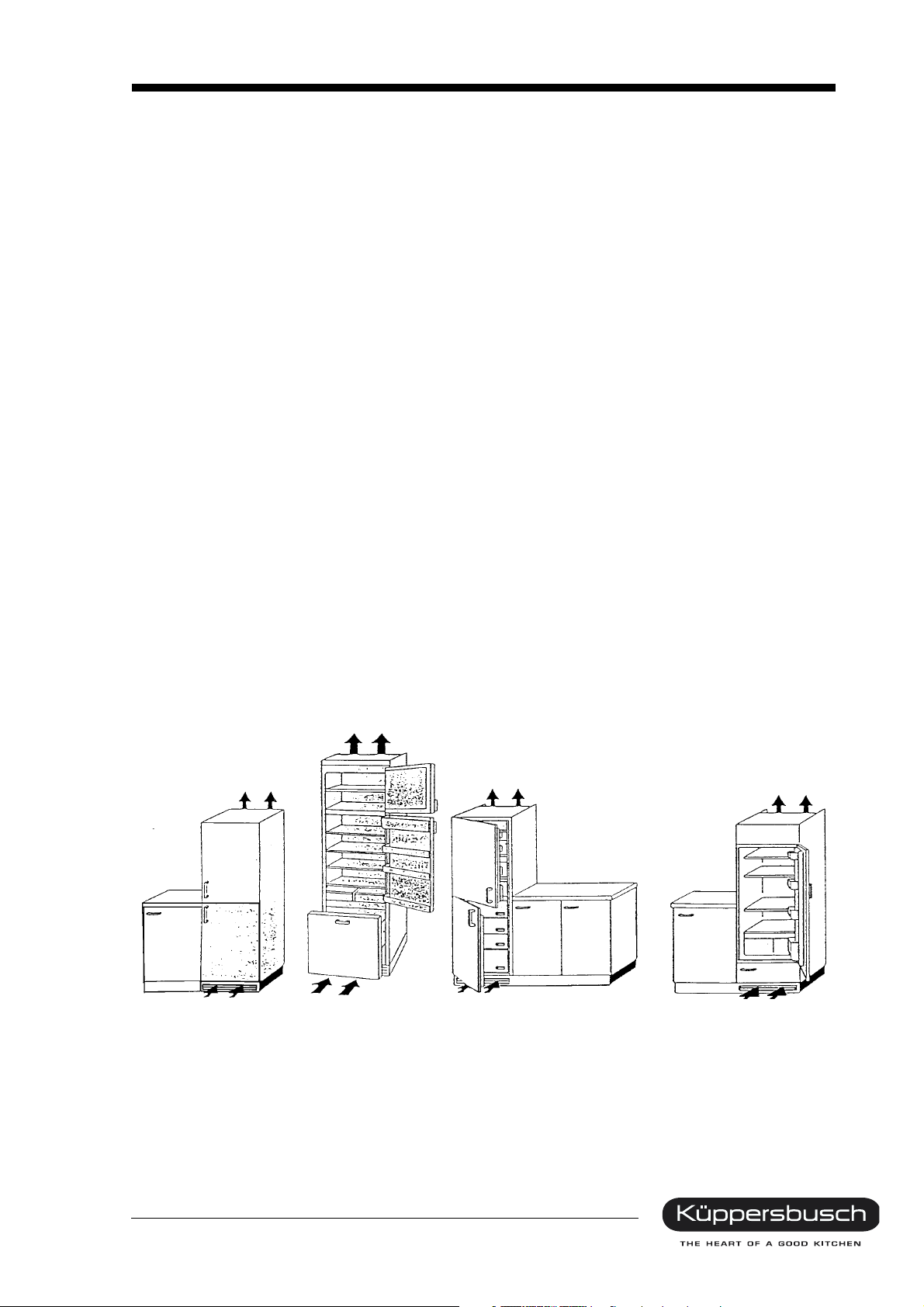
2.2 The design of the NO FROST appliances
In principle there are no restrictions as regards the appliance design.
All the usual designs in the field of refrigeration and freezing technology can also be produced using NO
FROST technology. The appliances are manufactured with up to a maximum of four doors. The doors
can be arranged adjacently or one above the other. With most appliances it is possible to adjust the
direction in which the door opens.
Three types of appliance are available: free-standing, built-under and built-in appliances.
Built-under appliances can be equipped with a decorative top panel.
Built-in appliances are completely integrated and adapted to match the front of the kitchen furniture.
The furniture door is fastened directly to the door of the appliance or to the furniture itself using sliding
hinges, all depending on the type of furniture.
Appliance design
Free-standing appliance
(fridge-freezer)
For internal use only
Free-standing appliance
(three-zone appliance)
Built-in appliance
(integrated fridge-freezer)
Built-in appliance
(integrated refrigerator)
6 H8-420-03-01Ä
2.3 Methods of refrigeration
At Küppersbusch we distinguish between 3 types of refrigeration:
a. Static refrigeration
Refrigeration by means of an evaporator, where the air flow factor is not increased by the auxiliary
device. With static refrigeration we depend on the normal circulation of air inside the appliance.
b. Dynamic refrigeration
The air is moved around the refrigeration cavity by means of a ventilator. This makes it possible to
achieve an even distribution of cold air inside the refrigeration cavity. Air is not lead through the
evaporator; instead it is circulated in the refrigeration cavity.
c. Refrigeration with circulating air
The air is distributed throughout the refrigeration cavity by means of a ventilator. The air is distributed in
such a way that it is conducted through the evaporator. In this way moisture condenses on the
evaporator so that the air inside the appliance remains dry.
Methods of refrigeration
1. Evaporator
2. Ventilator
3. Evaporation unit for condensed water
4. Compressor
For internal use only
H8-420-03-01Ä 7
2.4 NO FROST fridge-freezers
With NO FROST appliances we distinguish between models with only one compressor and models with
separate cooling circuits which have two compressors.
a. All NO FROST appliances with a refrigeration unit belonging to the Küppersbusch family of
domestic appliances are characterised by the same thermo-dynamic design. They differ only in
terms of capacity, dimensions and aesthetics.
The upper part of the appliance operates using the cyclic (static) refrigeration method; the lower
part of the appliance works by using the NO FROST method.
The temperature in both parts of the appliance is regulated by means of a thermostat fitted in the
refrigerator section.
The cooling circuit consists of the evaporator, which is fitted in the refrigerator section (also
completely integrated, depending on the model), and a battery evaporator which is fitted in the
freezer section.
The circuit is completed by a compressor, the condenser and two thermostats with capillaries of
varying lengths.
Due to the different capillaries, the appliances have different evaporator zones. The first and
absolute evaporator zone is located in the refrigerator section and the second in the freezer
section (battery evaporator).
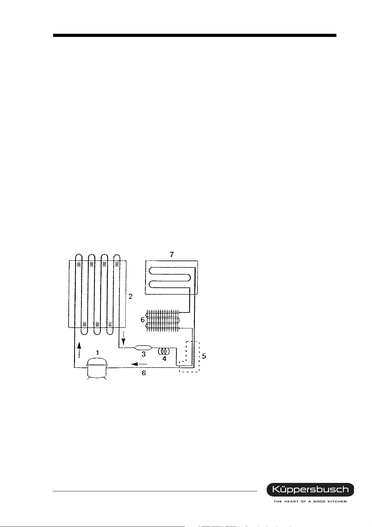
NO FROST cooling circuit in the single-compressor version
1. Compressor
2. Condenser
3. Dehydration filter
4. Capillary tube
5. Exchanger
6. Battery evaporator in freezer
section
7. Countersunk roll bonding
evaporator in refrigerator section
8. Return pipe
For internal use only
8 H8-420-03-01Ä
b. In addition to the NO FROST fridge-freezer appliances with one cooling unit, KÜPPERSBUSCH
also manufactures models with two compressors. These are appliances with a capacity of 300 l
and with 3 or 5 doors.
These models have two different cooling circuits.
The refrigerator section operates by means of cyclical cooling with one cooling unit and separate
temperature adjustment. A second cooling unit controls the NO FROST operation of the freezer
section and the 0° zone.
The temperature of each cooling circuit is controlled directly and separately by means of a
thermostat.
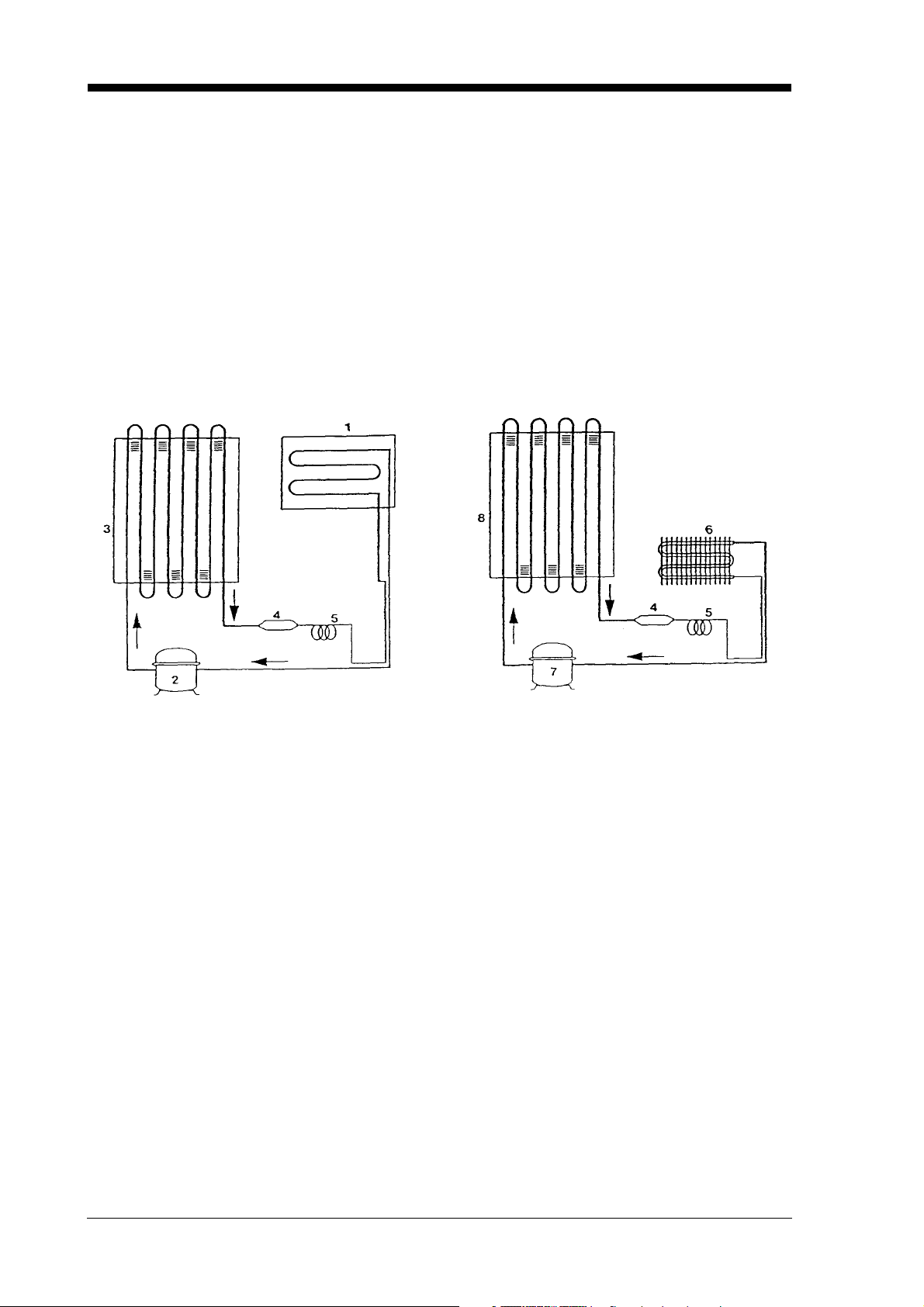
NO FROST dual-compressor version
1. Evaporator of the refrigerator section
2. Compressor of the refrigerator section
3. Condenser of the refrigerator section
4. Dryer
5. Capillary tube
6. Evaporator of the freezer section
7. Compressor of the freezer section
8. Condenser of the freezer section
(compressor area)
For internal use only

H8-420-03-01Ä 9
2.5 Installation and connection
Dry, well ventilated rooms present the best conditions for installing the fridge-freezers.
In order to keep electricity consumption low, the appliances should not be installed next to a cooker or
a radiator. Avoid direct sunlight.
When installed in a kitchen, fridge-freezers are arranged to fit in with normal work routines. It must be
ensured that the direction in which the door opens is the right one for the type of work carried out in the
kitchen.
Freezers - particularly freezer chests - can also be installed in a basement or cellar, in a basement
corridor or in a larder. If these rooms are damp, it is advisable to use an appliance with a condenser on
the outside wall.
Fridge-freezers are available in a number of different temperature groups which determine under what
ambient temperatures the appliances function to optimum satisfaction:
- Normal "N": Ambient temperature of between +16 °C and +32 °C
- Extended normal "SN": Ambient temperature of between +10 °C and +32 °C
- Subtropical "ST": Ambient temperature of between +18 °C and +38 °C
- Tropical "T": Ambient temperature of between +18 °C and +43 °C
(Source: DIN 8950)
The sign indicating these limits appears on the rating label. The fridge-freezers used in Germany almost
all belong to class "N", i.e. avoid installing them in a room where a temperature of less than +16 °C or
more than +32 °C can be reached as the temperature regulation device of the appliances will then fail
to function correctly. This has particularly adverse effects in refrigerators with an evaporator
compartment and in fridge-freezers with only one cooling circuit.
Freezers only function correctly in an ambient temperature of approx. 0 °C.
On no account should the appliance be installed in a place where the temperatures exceed +32 °C.
Fridge-freezers are supplied ready to plug in and are connected to a protected socket. For refrigerators
the wattage is roughly between 100 W and 240 W and between 145 W to 265 W for fridge-freezers.
Freezers have a wattage of between 100 W and 300 W. For reasons of safety the freezer should have
a separate electricity circuit. This ensures that it will continue to operate when the circuit becomes
overloaded due to other appliances being connected or when the electricity circuit is interrupted due to
another appliance becoming defective.
For internal use only
10 H8-420-03-01Ä
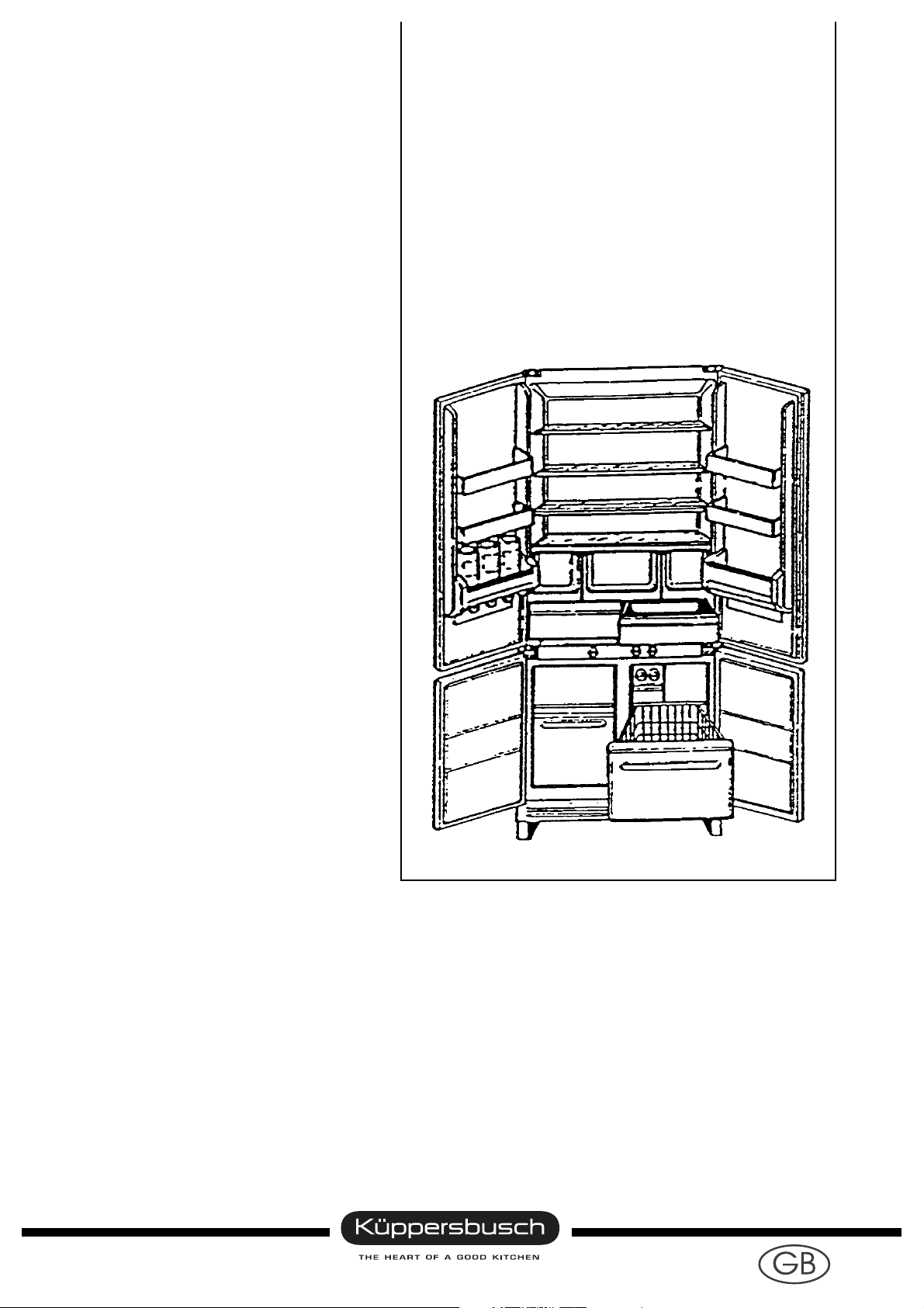
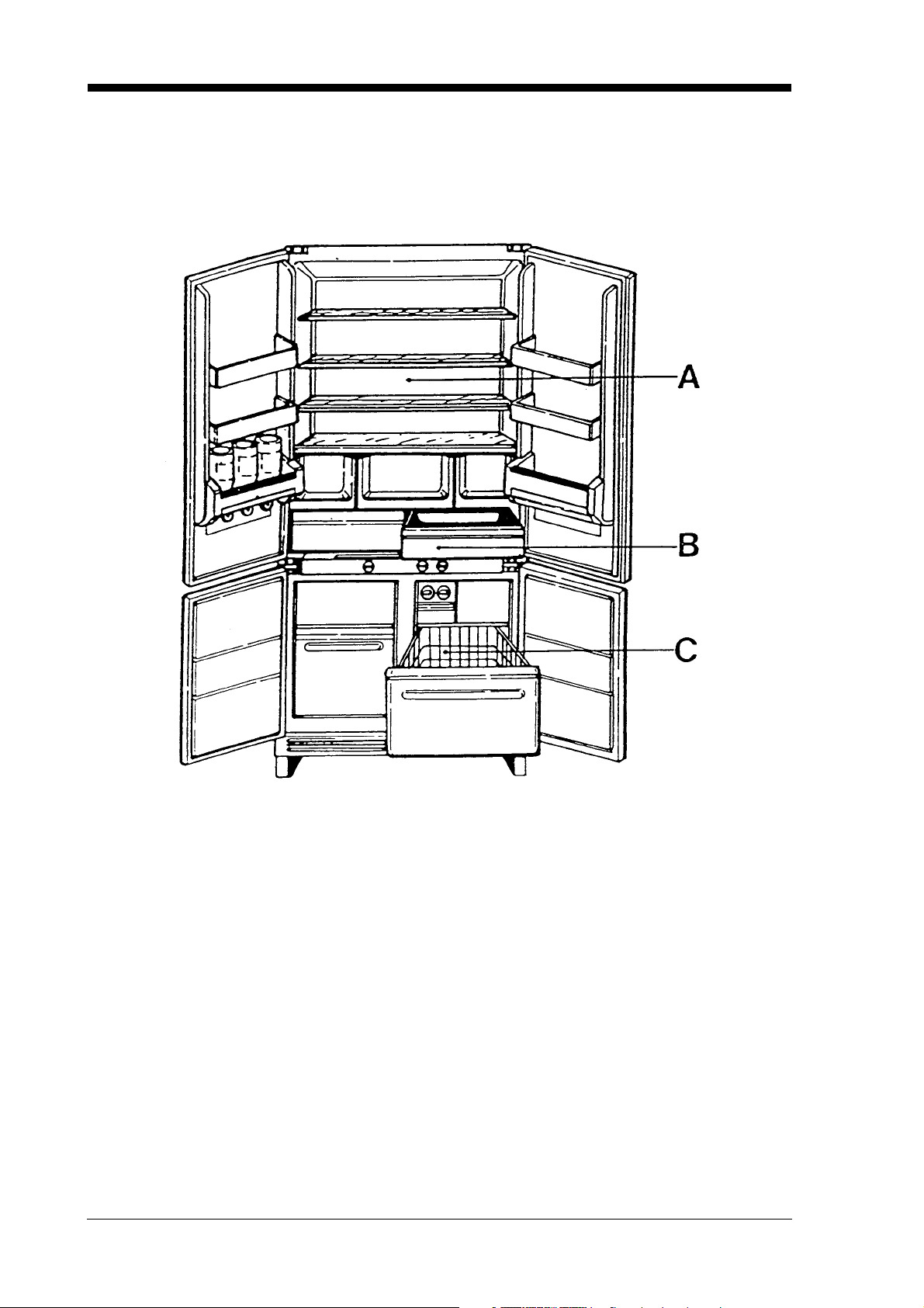
3. The fully integrated 3-zone fridge-freezer
3.1 The various zones
A - Refrigerator
B - 0 °C zone
C - Freezer
For internal use only

H8-420-03-01Ä 11
Multi-zone appliances enable the customer to make use of 3 refrigeration zones for optimum storage of
all types of food.
The refrigeration sections in detail:
Refrigeration section A:
Here an ideal environment is created for the storage of fresh food. This section employs an evaporator
made of an integrated aluminium sheet and the temperature is controlled by means of an adjustable
thermostat on the operation panel.
Refrigerator section B:
This refrigeration section has even temperatures of between 0 °C and 3 °C. Refrigeration is by means
of the enforced convection of air from the lower freezer section. The temperature control in this section
is regulated by means of a special flap thermostat (mechanically). Even temperatures are guaranteed,
even during defrosting.
Freezer section C:
The cold air is generated by a battery evaporator and the enforced convection of the air is effected by
means of a ventilator.
This means that moist air in the form of frost only condenses on the evaporator and not on the walls of
the freezer section or on packages of food. A timer activates a defrost resistor at regular intervals
(depending on the model every 12 – 14 hours). It is not possible for the compressor to start up. As soon
as the temperature of the evaporator reaches +10 °C, the power supply of the heating resistor is
interrupted by a thermal switch during defrosting.
A further safety thermal switch interrupts the power supply to the thermal resistor when the temperature
of the battery evaporator rises to abnormal levels (+30 °C /+40 °C) due to a malfunction.
The temperature in the freezer is clearly indicated by means of various LEDs on an electronic
thermometer located on the operation panel.
The temperature is regulated by means of an adjustable thermostat on the operation panel.
The 3-zone appliance has two cooling circuits.
For internal use only

12 H8-420-03-01Ä
3.2 Technical data:
IK 458.1-4T IK 458.2-4T
General features
Dimensions HxWxD 190x86x55 cm 190x86x55 cm
Gross capacity:
Refrig./ freezer/ 0° zone 274 / 128 / 45 l 274 / 128 / 45 l
Cooling:
Refrig./ freezer/ 0° zone cyclical / **** / 0-3°C cyclical / **** / 0-3°C
Amount of cooling agent: R12 R134a
Refrig./ freezer 90 / 160 g 75 / 130 g
Class N N
Refrigerator:
Thermostat:
Minimum setting:
Switching on / switching off +4.5 / -12°C +4.5 / -12°C
Maximum setting:
Switching on / switching off +4.5 / -22°C +5 / -24°C
Motor compressor
Operating voltage 220-230 V / 50 Hz 220-240 V / 50 Hz
Power of motor 1/8 HP 1/8 HP
Power consumption 93 W 89 W
Nominal / starting current 0.6 / 3.5 A 0.5 / 2.7 A
Resistance of main and auxiliary winding 20 / 21 ohms 25 / 26 ohms
Cooling output 83 Kcal/h 92 Kcal/h
Freezer
Thermostat:
Minimum setting:
Switching on / switching off -11 / -20°C -11 / -20 °C
Maximum setting:
Switching on / switching off -26 / -34 °C -26 / -34 °C
Motor compressor / KS
Operating voltage 220-240 / 50 / V/Hz 220-240 / 50 / V/Hz
Power of motor 1/5 HP 1/5 HP
Power consumption 150 W 149 W
Nominal / starting current 0.7 / 4.7 A 0.8 / 4.8 A
Resistance of main and auxiliary winding 12 / 14 ohms 12 / 14 ohms
Cooling output 169 Kcal/h 204 Kcal/h
Operating condensor 5 !F 5 !F
For internal use only

H8-420-03-01Ä 13
IK 458-2-2T IK 458-4-4T
General features
Dimensions HxWxD 190x86x55 cm 190x86x55 cm
Gross capacity
Refrig./ freezer/ 0° zone 266 / 96 / 28 l 266 / 96 / 28 l
Cooling:
Refrig./ freezer/ 0° zone cyclical / **** / 0-3°C cyclical / **** / 0-3°C
Amount of cooling agent: R134a R600a
Refrig./ freezer 75 / 130 g 38 / 60g
Class N SN
Refrigerator:
Thermostat:
Minimum setting:
Switching on / switching off +4.5 / -12°C +5 / -3.5°C
Maximum setting:
Switching on / switching off +4.5 / -22°C +5 / -24°C
Motor compressor
Operating voltage 220-240 V / 50 Hz 220-240 V / 50 Hz
Power of motor 1/8 HP 1/12 HP
Power consumption 89 W 60 W
Nominal / starting current 0.5 / 2.7 A 0.29 A
Resistance of main and auxiliary winding 25 / 26 ohms 38.5 / 26 ohms
Cooling output 92 Kcal/h 60 Kcal/h
Freezer
Thermostat:
Minimum setting:
Switching on / switching off -11 / -20°C -12 / -20.5°C
Maximum setting
Switching on / switching off -26 / -34°C -23 / -34°C
Operating voltage 220-240 V / 50 Hz 220-240 V / 50 Hz
Power of motor 1/5 HP 1/6 HP
Power consumption 149 W 131 W
Nominal / starting current 0.8 / 4.8 A 0.9 / 4.9 A
Resistance of main and auxiliary winding 12 / 14 ohms
Cooling output 169 Kcal/h 204 Kcal/h
Operating condensor 5 !F 5 ! F
For internal use only
14 H8-420-03-01Ä
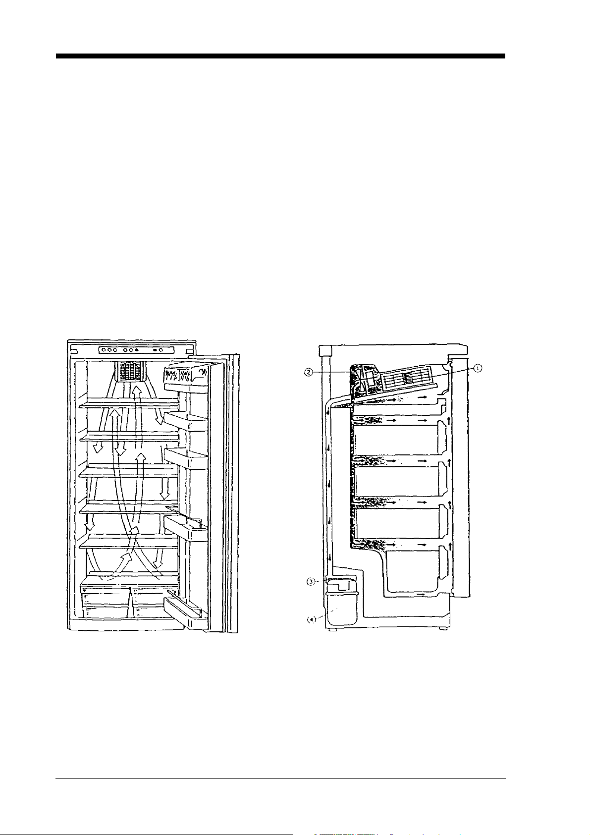
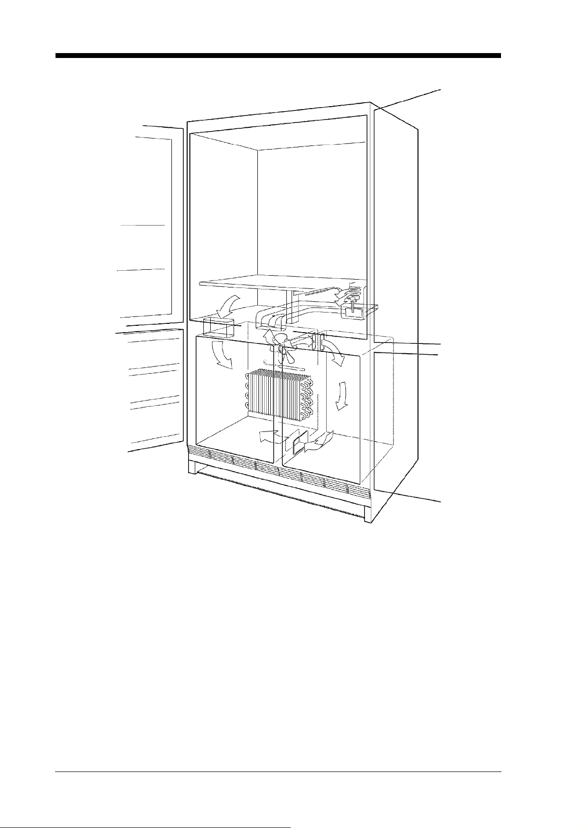
3.3 Air circulation
Freezer section: the air produced by the battery-driven evaporator is put into circulation by the fan,
which is located above the battery. The air flows into the right-hand compartment of the freezer and flows
out again through two slits.
The temperature is controlled by the thermostat bulb which can be seen installed right above the battery.
Zero-degree zone: the air flows in through a foamed duct above the fan and flows out through the slits
of the flap thermostat. The air can flow back into the freezer section through a slit on the bottom left of
the zero-degree zone. The temperature is regulated by the flap thermostat.
Refrigerator section: the air is circulated by means of natural air convection. The flow is regulated by
the built-in thermostat bulb.
For internal use only
 Loading...