

Kuppersbusch EKDG 6800.0, EEBD 6600.0, EKDG 6800.0-75, EKDG 6800.1, EDG 6600.0 Service Manual
...
`згДбеЙЗ=pнЙ~г=lоЙел
bb_a SSMMKM bad SSMMKM bhad SUMMKM
bad SSMMKN bhad SUMMKN
bhad SUMMKO
bhad SUMMKMJ
TR
Service Manual: H3-72-01
Model Type
EEBD 6600.0 858
EKDG 6800.0 856
EKDG 6800.0-75 875
EKDG 6800.1 699
EKDG 6800.2 687
EDG 6600.0 855
EDG 6600.1 698
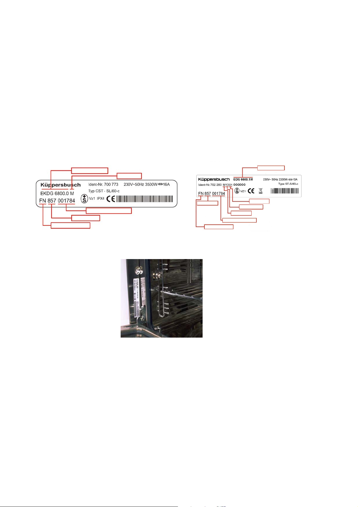
Sample of a model identification plate (until 06/2007) model identification plate (from 06/2007)
Model name
Date of productio n
Serial number
Model name
Consecutive appliance number
Model number
Type of variation
Model number
Serial number
Month produced
Year produced
Consecutive appliance number
The model identification plate is visible on the left-hand side of the frame when the flap is opened
Responsible: D. Rutz KÜPPERSBUSCH HAUSGERÄTE AG
Tel.: (0209) 401-733 Kundendienst
Fax: (0209) 401-743 Postfach 100 132
Date: 22. 8. 2007 45801 Gelsenkirchen

H3-72-01 3
Contents
1. Safety ............................................................................................................................... 5
2. General ............................................................................................................................ 6
3. Appliance overview ........................................................................................................ 7
3.1 EDG 6600.1........................................................................................................... 7
3.2 EDG 6600.0........................................................................................................... 9
3.3 EEBD 6600.0....................................................................................................... 11
3.4 EKDG 6800.0 ...................................................................................................... 16
3.5 EKDG 6800.1 / EKDG 6800.2 ............................................................................. 20
4. Installation..................................................................................................................... 23
4.1 Safety instructions for technicians....................................................................... 23
4.2 Installation EDG / EKDG ..................................................................................... 23
4.3 Installation EEBD 6600.0 .................................................................................... 25
5. EDG / EKDG appliance components .......................................................................... 28
5.1 Limestone sensor ................................................................................................ 28
5.2 Level sensor (point gauge).................................................................................. 28
5.3 Water system ...................................................................................................... 29
5.4 Automatic altitude adjustment ............................................................................. 31
5.5 Floor heater 140 W with protection against an excessive rise in temperature .... 32
5.6 Recognising a steam leak with the climatic sensor ............................................. 33
5.7 Fan, follow-on time and steam dissipation .......................................................... 33
5.8 Slide with a magnetic lifting cylinder.................................................................... 34
5.9 Electric connecting box ....................................................................................... 35
6. Appliance components: EEBD 6600.0 ........................................................................ 36
6.1 Water tank microswitch ....................................................................................... 37
6.2 Cross-current fan for the cooling air .................................................................... 37
6.3 Revolution counter for the cross-current fan ....................................................... 38
6.4 Removing the air system ..................................................................................... 38
6.5 Door switch (reed contact) .................................................................................. 39
6.6 Discharge pump with a filter for “dynamic filtering” ............................................. 39
6.7 Bottom heat inner / outer circuit .......................................................................... 39
6.8 Protection against excessive temperatures 2 x 280°C........................................ 40
6.9 Replacing a Pt 500 sensor seal........................................................................... 40
6.10 Complete evaporator 1400 W / 230 V ................................................................. 41
6.11 Climatic sensor .................................................................................................... 41
6.12 Drive (step motor) / exhaust air slide................................................................... 41
6.13 Water tank ........................................................................................................... 42
6.14 Water intake / water discharge ............................................................................ 43
6.15 Solenoid valve ..................................................................................................... 44
6.16 Building up steam in the evaporator (heater activated) ....................................... 44
7. Operational modes ....................................................................................................... 47
7.1 Steaming ............................................................................................................. 48
7.2 Regenerating ....................................................................................................... 52
7.3 Baking like professionals ..................................................................................... 55
7.4 Hot air.................................................................................................................. 59
7.5 Hot air with steam vapours (EEBD 6600.0)......................................................... 62
For internal use only

4 H3-72-01
7.6 Grill (EEBD 6600.0) ............................................................................................. 64
7.7 Pizza Plus (EEBD 6600.0)................................................................................... 65
7.8 Slow cooking (EEBD 6600.0) .............................................................................. 66
7.9 Top / bottom heat (EEBD 6600.0) ....................................................................... 67
7.10 Legend................................................................................................................. 68
8. General information on operation and the demonstration mode............................. 69
8.1 Demonstration mode (EDG 6600.0 and EDG 6600.1) ........................................ 69
8.2 Demonstration mode (EKDG 6800.0 and EKDG 6800.0-75) .............................. 70
8.3 Demonstration mode (EKDG 6800.1 and EKDG 6800.2) ................................... 70
8.4 Demonstration mode (EEBD 6600.0) .................................................................. 70
9. Error and alarm messages........................................................................................... 71
9.1 Overview of reference messages ........................................................................ 72
9.2 Schedule of U-fault messages (power supply fault) ............................................ 72
9.3 Schedule of H-fault messages (only EEBD and EDG) ........................................ 73
9.4 Fault schedule (EDG 6600.0 and EDG 6600.1) .................................................. 74
9.5 Fault schedule EKDG 6800.0 .............................................................................. 75
9.6 Fault schedule EKDG 6800.1 .............................................................................. 77
9.7 Fault schedule EKDG 6800.2 .............................................................................. 79
9.8 Fault schedule EKDG 6800.0-75......................................................................... 81
9.9 Fault schedule: EEBD 6600.0 .............................................................................82
10. Wrong behaviour .......................................................................................................... 86
10.1 Food temperature sensor .................................................................................... 87
10.2 Water temperature sensor ................................................................................... 88
10.3 Steam leak........................................................................................................... 88
10.4 Heating spiral sensor and steam temperature sensor ......................................... 89
10.5 Boiler heater ........................................................................................................ 90
10.6 Water level pin ..................................................................................................... 90
10.7 Emptying.............................................................................................................. 91
10.8 Boiler and water level pin scaled ......................................................................... 92
10.9 Non-return valve on the water tank leaks (EEBD 6600.0) ................................... 92
10.10 Water tank leaks (EEBD 6600.0)......................................................................... 93
11. Descale .......................................................................................................................... 94
11.1 EDG and EKDG...................................................................................................94
11.2 EEBD 6600.0 ....................................................................................................... 95
11.3 Flow chart: Descaling programme (EEBD 6600.0).............................................. 97
For internal use only
H3-72-01 5
1. Safety
Danger!
Repairs may only be carried out by a qualified electrician! Inexpert repairs may
lead to risks and damages for the user!
To prevent electric shocks, please observe the following tips:
• In the event of faults, housing and frame may be live!
• Touching live components inside the appliance may cause dangerous currents to flow through your
body!
• Prior to repairs, disconnect the appliance from the mains!
• When inspecting live parts, a residual current operated device must be used at all times!
• The ground wire resistance must not exceed that specified in the standard! It is of vital importance
for ensuring the safety of people and the functioning of the appliance.
• On completion of repairs, an inspection must be carried out in accordance with VDE 0701
[Association of German Electrical Engineers] or the corresponding regulations for your country!
• On completion of repairs, a function and impermeability inspection must be carried out.
Caution!
Make sure you observe the following instructions:
• The appliances must be disconnected from the mains prior to all repairs. If inspections must be
carried out on live appliances, make sure you use a residual current operated device.
Sharp edges: Use protective gloves.
Components may be electrostatic!
Observe handling precautions!
For internal use only

6 H3-72-01
2. General
Depressurised steam cooking involves cooking food with a combination of steam and hot air. Gentle
steam cooking at temperatures of between 40°C – 100°C optimally preserves vitamins and minerals as
well as maintaining colours and natural aromas. Food does not dry out and nor will it burn or stick.
Since only a relatively small amount of water needs to be heated, steam cooking means that a great deal
of time and energy can be saved.
Depressurised steam cooking takes place at temperatures of between 40 °C and 100 °C, thus making it
easy to cook food just as it is required. The climatic sensor steams the food in just the right conditions,
irrespective of the quantity of food being cooked. Instead of being destroyed, vitamins and minerals are
largely preserved. Flavour, colour and consistency are maintained – food does not lose its structure.
There is therefore almost no need to add salt and spices.
To sum up: cooking with steam makes conscious, healthy eating possible without any extra effort. The
steam cooker provides excellent possibilities in combination with the ökotherm
It is particularly when meat is being cooked that the oven becomes dirty due to squirting juices. Dirt which
has become dried can be removed more easily if the cooker, prior to cleaning, is operated with the
“steam” cooking mode at a temperature of 100 °C for approximately 30 minutes, thus softening any
soiling. After being used for some time the oven will take on a golden colour.
®
cooker or oven.
For internal use only
H3-72-01 7
3. Appliance overview
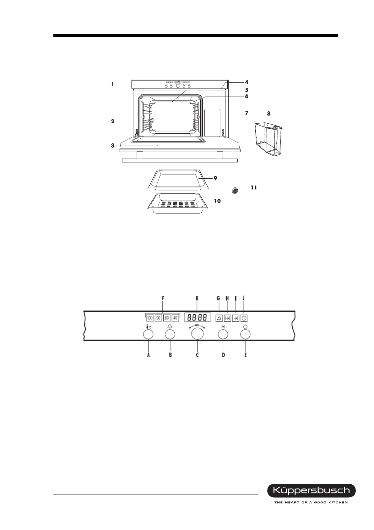
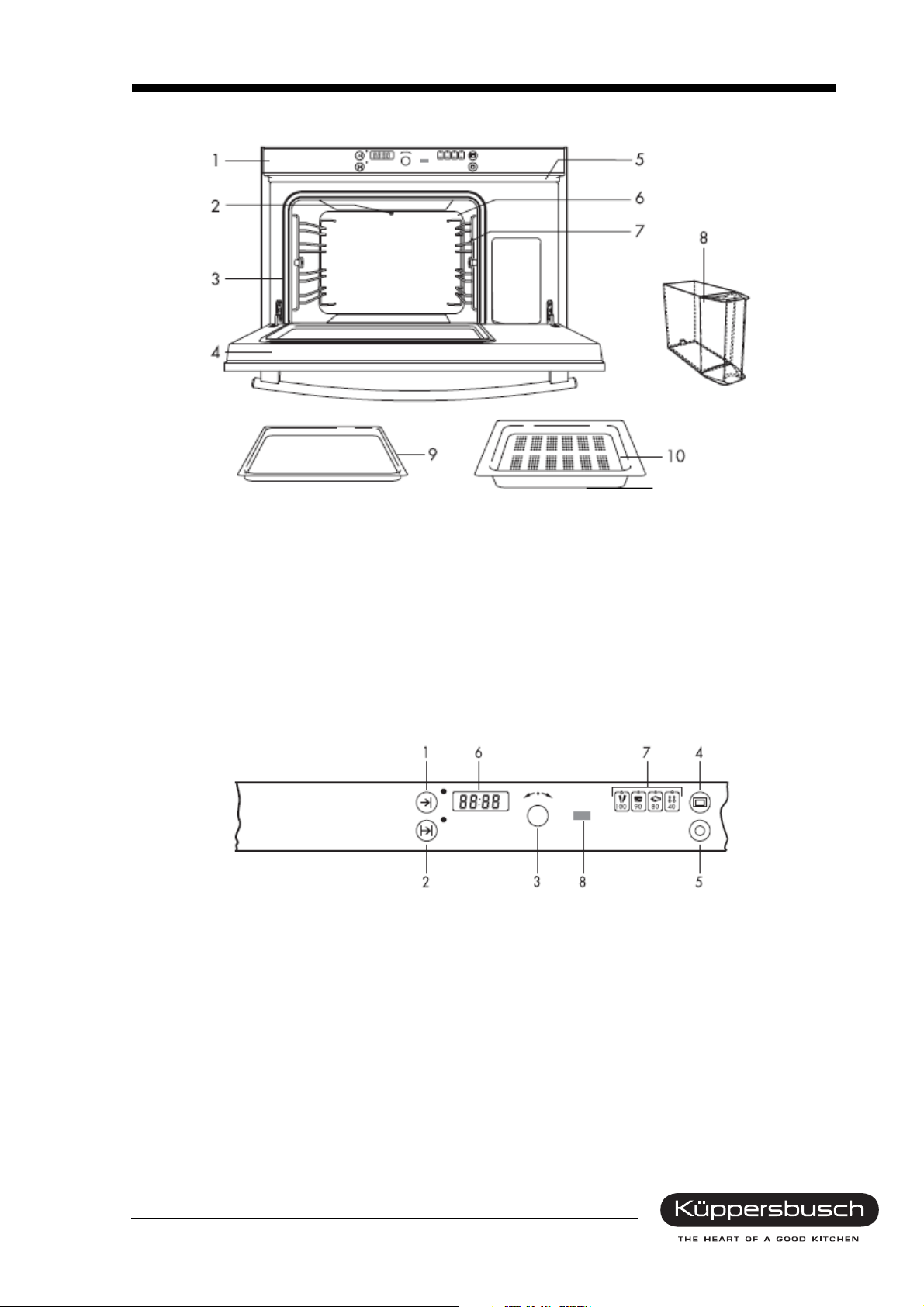
3.1 EDG 6600.1
1 Control and display elements 7 Supporting grid
2 Oven temperature sensor 8 Water tank
3 Door seal 9 Stainless steel baking tray
4 Appliance door 10 Perforated cooking pan
5 Air vent slit 11 Water filter (3 filters)
6 Steam inlet
3.1.1 Control elements
A Operating mode
BTimer
C Adjusting knob
D Operating time and switch-off time
E Switching off
Displays
K Time, cooking time and timer
For internal use only
8 H3-72-01
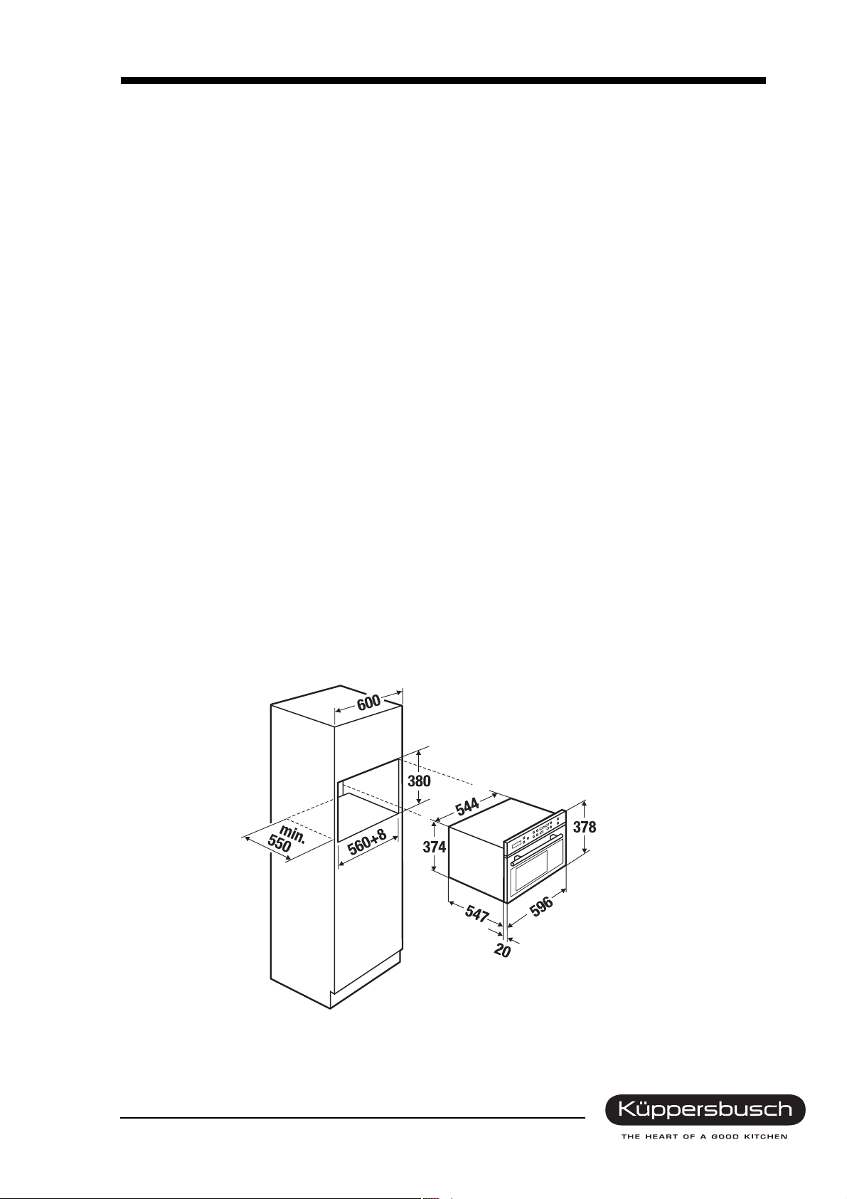
3.1.2 Technical data
Appliance dimensions Oven dimensions Niche dimensions
Height
Width
Depth
Weight
37,8 cm 25,0 cm 38,0 cm
54,8 cm 35,9 cm
55,1 cm 39,0 cm
47 kg
at least 58,0 cm
at least 55,0 cm
Electrical connection
Connection voltage 230V ~50 Hz
Power Connected wattage 2,2 kW
Electrical voltage
10 A
Heating power
Steam generator 2,0 kW
Floor heater 0,15 kW
Safety concept
The appliance will be monitored by the electronic control system for as long as it is supplied with power.
Any faults which occur will be shown in the clear text display.
Maximum load: 2 kg
For internal use only
H3-72-01 9
3.2 EDG 6600.0
1 Control and display elements 6 Steam inlet
2 Oven temperature sensor 7 Supporting grid
3 Door seal 8 Water tank
4 Appliance door 9 Stainless steel baking tray
5 Air vent slit 10 Perforated cooking pan
3.2.1 Control elements
Buttons / adjusting elements
1 Switch-off time with a control light
2 Operating time with a control lamp
3 Knob
4 Operating mode with a control light
1 Switching off with a control light
Displays
6 Time / Remaining time / Operating time / Switch-off time
7 Operating mode
For internal use only
10 H3-72-01
3.2.2 Technical data
Appliance dimensions Oven dimensions Niche dimensions
Height
Width
Depth
Weight
Maximum load
37.8 cm 25.0 cm 38.0 cm
54.8 cm 35.9 cm
55.1 cm 39.0 cm
47 kg
2kg
at least 58.0 cm
at least 55.0 cm
Electrical connection
Connection voltage 230V ~50 Hz
Power Connected wattage 2.2 kW
Electrical voltage
10 A
Heating power
Steam generator 2.0 kW
Floor heater 0.15 kW
Safety concept
The appliance will be monitored by the electronic control system for as long as it is supplied with power.
Any faults which occur will be shown in the clear text display.
For internal use only
H3-72-01 11
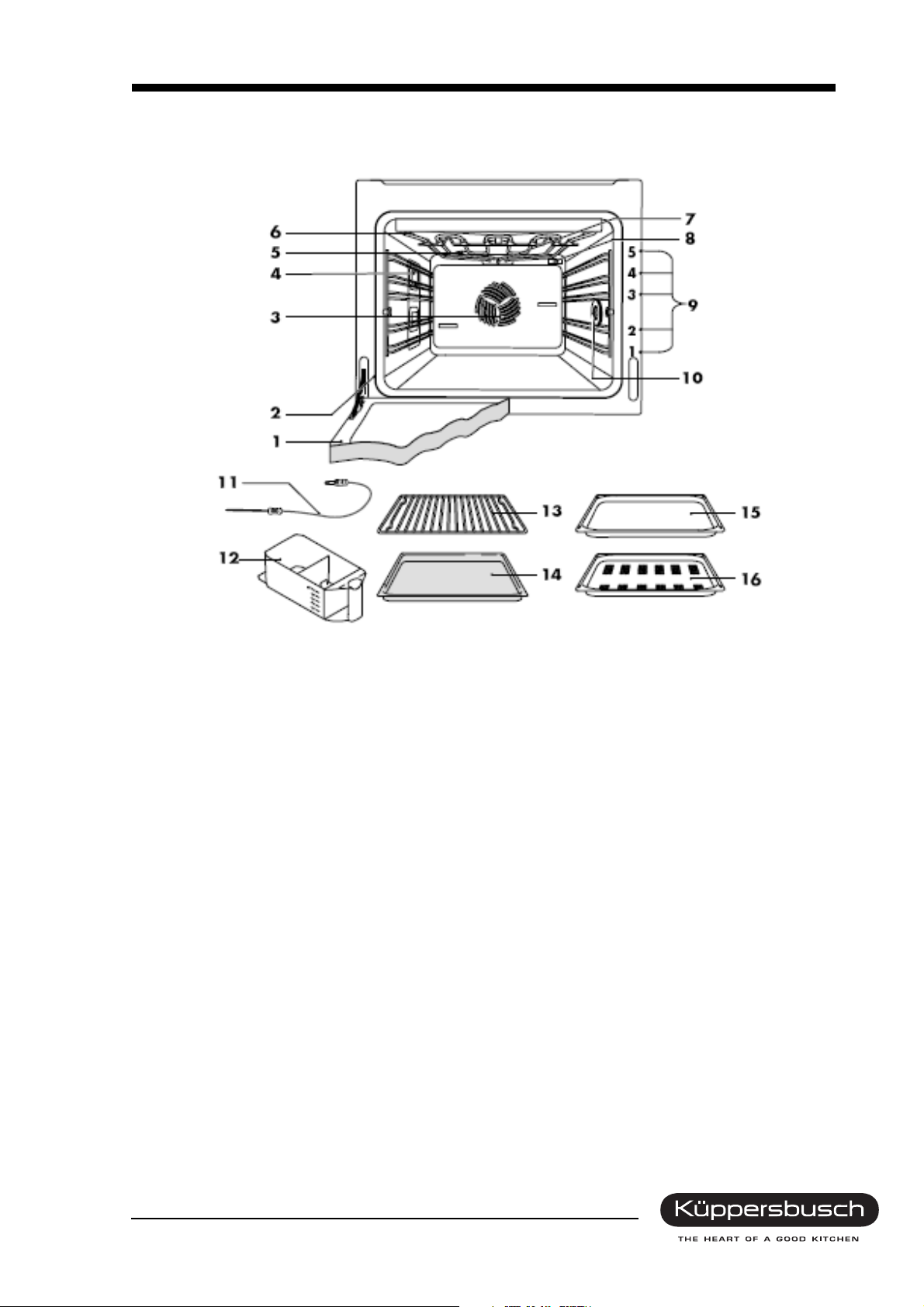
3.3 EEBD 6600.0
1 Appliance door 6 Grill/top heat
2 Door seal 7 Oven temperature sensor
3 Hot air blower 8 Steam inlet
4 Illumination 9 Supports
5 Oven ventilating system 10 Socket for the food probe
Accessories
11 Food probe
12 Water tank
13 Roasting grid
14 Original baking tray
15 Stainless steel baking tray
16 Perforated cooking pan
For internal use only
12 H3-72-01
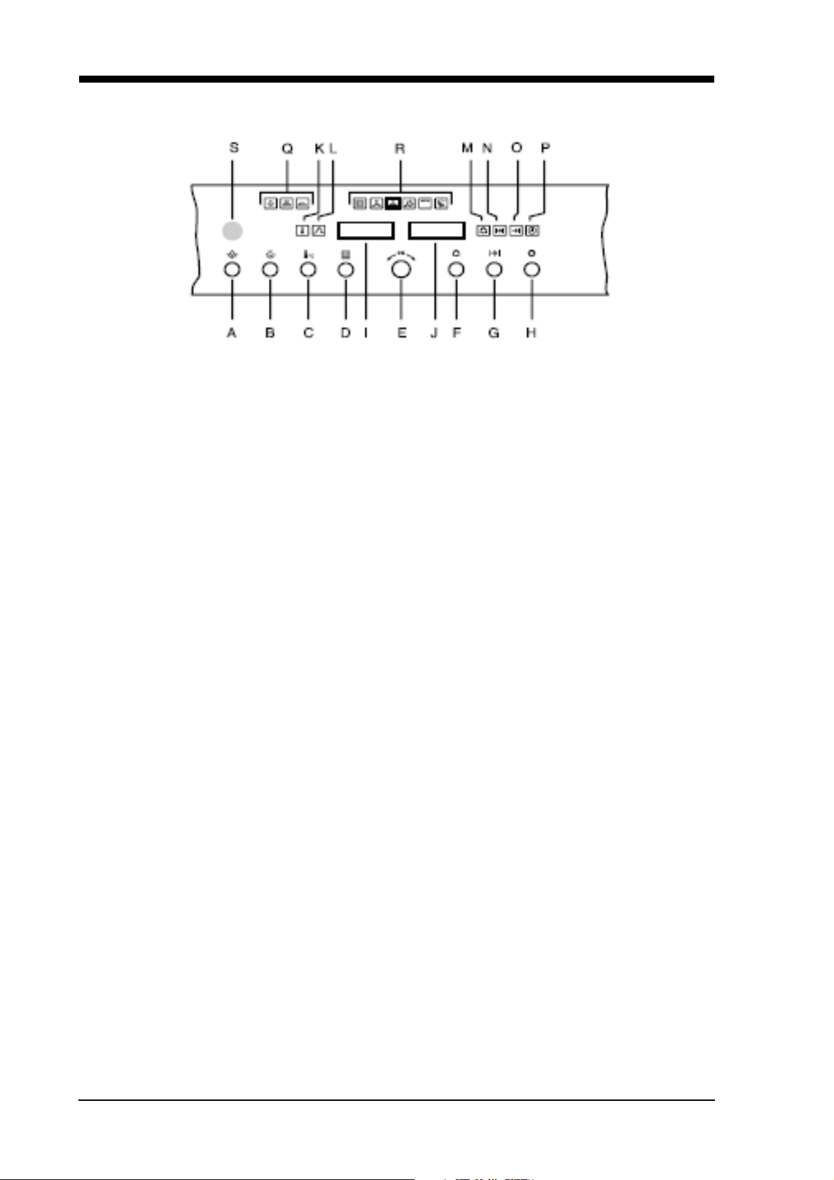
3.3.1 Control elements
Buttons / adjusting elements Displays
A Illumination I Temperature
B Operating mode using steam J Time / cooking time and timer
C Oven/food probe temperature
D Operating mode without any steam
E Adjusting knob
FTimer
G Operating time / Switch-off time
H Switching off
Symbols
K Oven temperature P Time
L Food probe temperature Q Operating mode using steam
M Timer R Operating mode without any steam
N Operating time S Draught eye
O Switch-off time
General information on operation
Select the various operating modes, the oven temperature and the core temperature as well as the
duration and various other functions by pressing the respective key once or more often.
• The symbol for the function selected will light up or blink.
• A proposal will blink in the display.
• Turning knob E will adjust the proposed setting.
• The appliance will start up immediately when knob E is pressed. If the knob is not pressed the
appliance will start up approx. 15 seconds after the last setting was made. Settings can be made
or adjusted at any time.
• The appliance will switch off when key H is pressed.
• Settings can be made with the knob after the button for the respective mode of operation has been
pressed.
• Once the button has been pressed settings can be changed for a short time.
For internal use only
H3-72-01 13
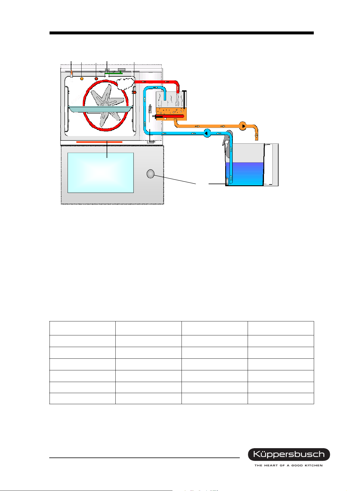
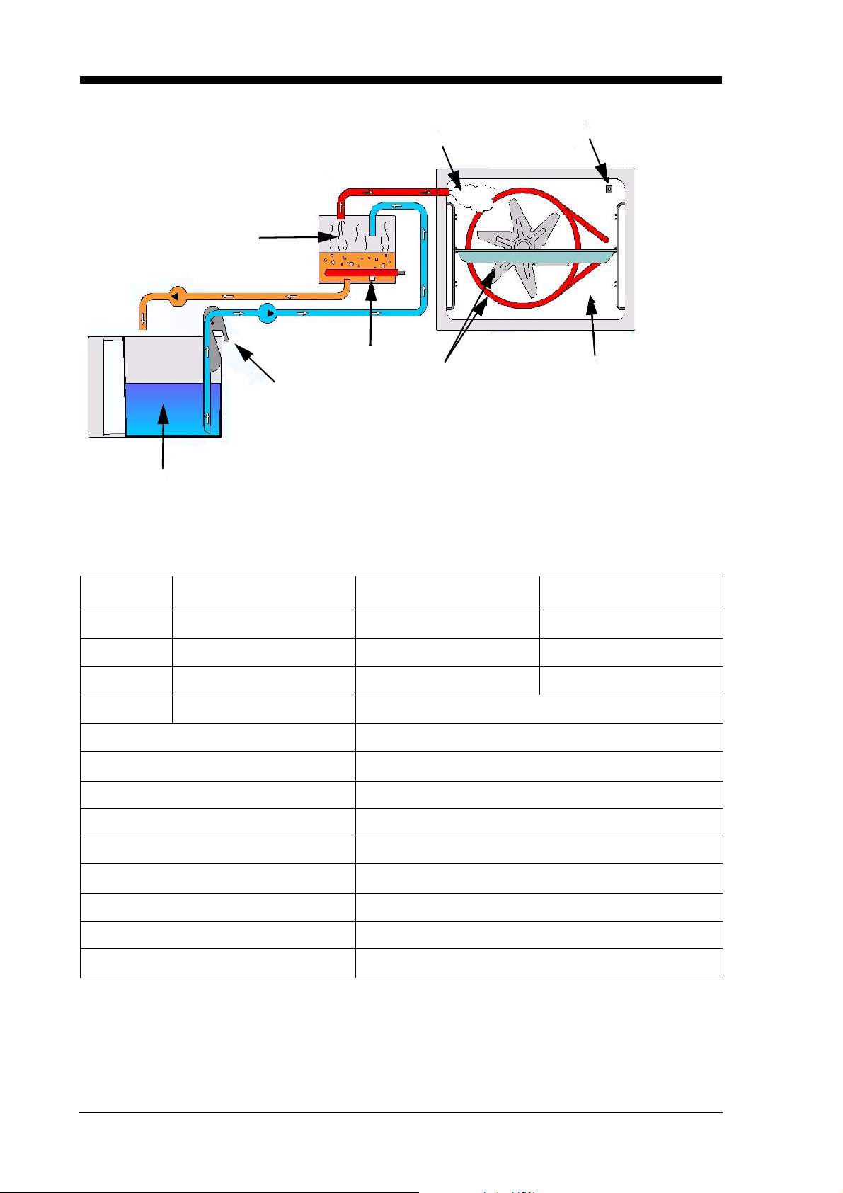
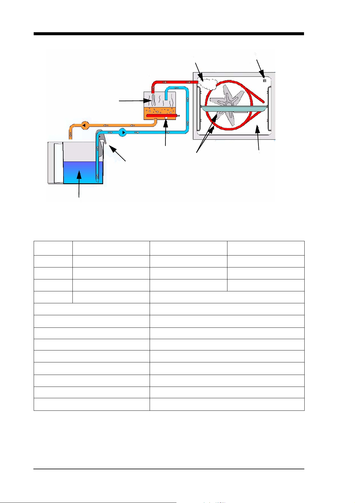
3.3.2 Appliance structure
12 5
Disc
4
3
Floor heater
Door
1 Air temp. NTC 25°C/10kΩ
2 Protection against excessive temperatures
Oven 135°C
3 Temp. oven PT 500 PTC 25°C/550kΩ
4 Inlet air
5 Food sensor
6 Condenser water conductance
11
6
7
9
8
Water
tank
1.25 l
10
7 Water pump empty water below 80°C
8 Water pump suction
9 Condenser water temperature
NTC 25°C/10kΩ
10Ignition solenoid
11Reed switch
3.3.3 Technical data
Appliance dimensions Oven dimensions Niche dimensions
Height
Width
Depth
Weight
Oven 50 l
Water tank, removable approx. 1.25 l
For internal use only
59.8 cm 60.0 cm
59.6 cm 56.0 cm
56.7 cm at least 55.0 cm
47 kg
14 H3-72-01
Heating power
Hot air heater: 2.2 kW
Steam generator 1.4 kW
Floor heater -
Top heat 1.2 kW
Bottom heat 1.25 kW
Grill 2.5 kW
Total output 3.7 kW
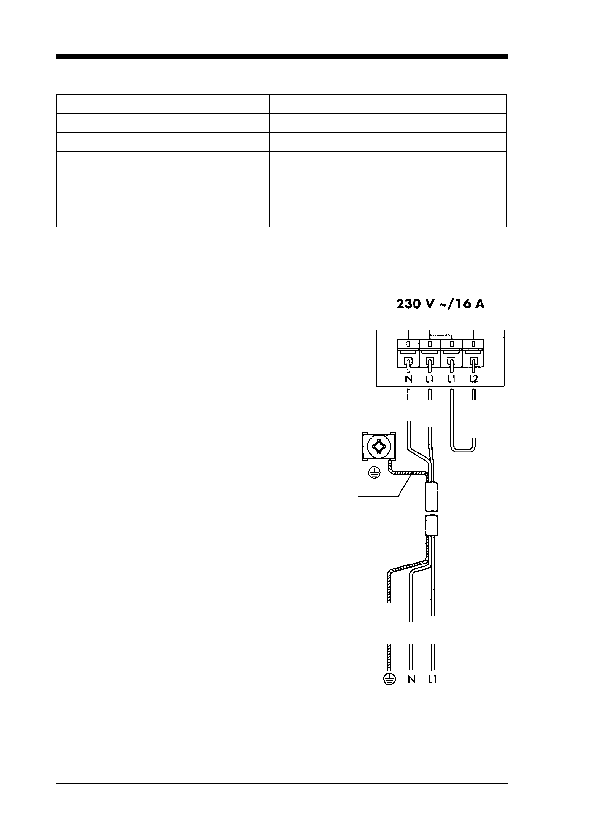
Electric supply
Connection voltage 230 V ~50 Hz or 400 V
2N ~50 Hz
Connected load 3.5 kW (230 V) / 2.2 kW
Output Connected load 3.5 kW / 2.2 kW
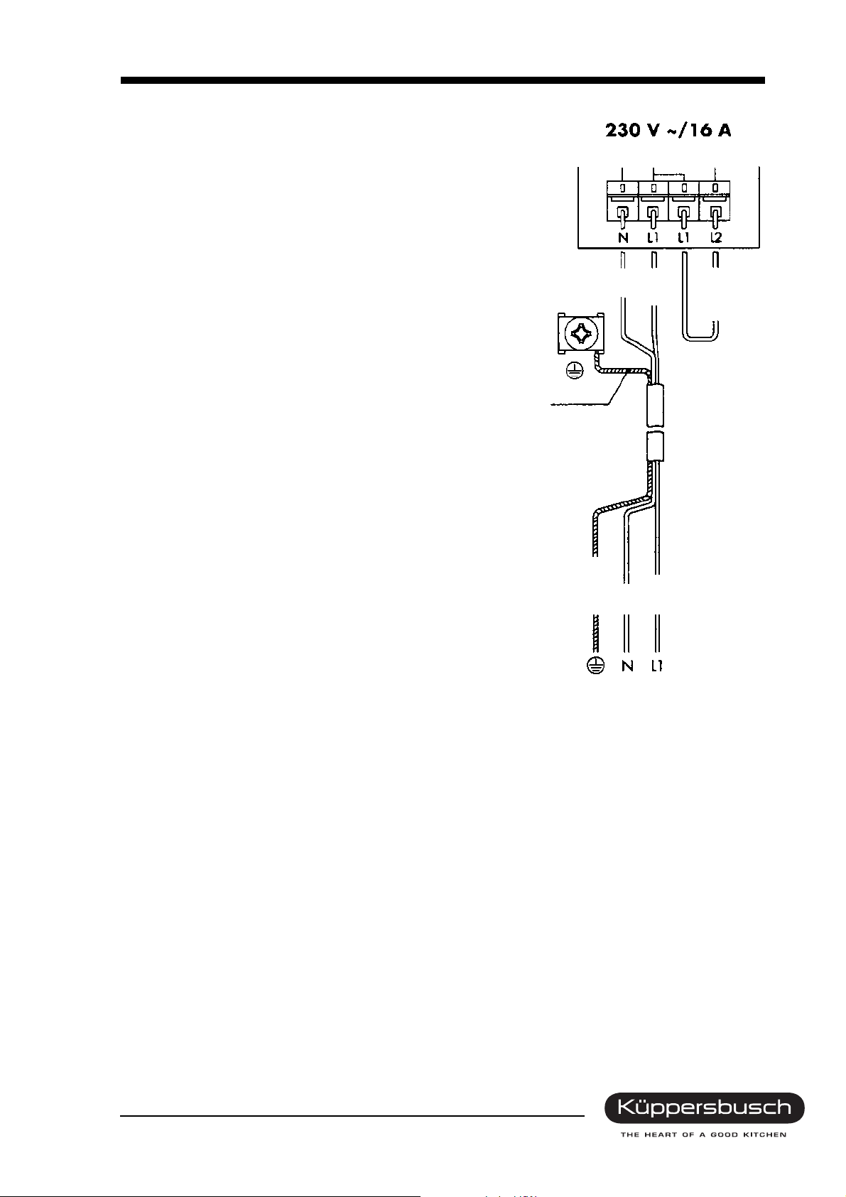
Voltage 16 A (230 V) or 10 A (400 V)l
Electric connection 230~/16 A with a single phase socket
system (see illustration)
Due to the mains cable of 3.5 kW the appliance will need
to be protected by a 16 A fuse. The appliance must be
wiring as shown on the illustration.
New electronic system features
• Completely new computer component (not
compatible with 756/EKDG 6800.0)
• No power monitor circuit (suitability for export)
• Brightness of the clock display improved
• No longer any phase for the exhaust fan (only relay)
• The boiler heater is activated by a relay instead of
with a triac
• Completely new operating element (not compatible
with 756/EKDG 6800.0)
• Completely new operating element and text display
(not compatible with 756/EKDG 6800.0)
• New rotary encoder with a button (more stable and
better)
yellow-green
yellow-green
blue
brown
brown
blue
black
For internal use only

H3-72-01 15
Technical features
• Clear text display with a program indicator
• Climatic sensor
• Limestone sensor
• Permanent control of oven humidity
• External steam generator
• Electronic temperature control and display
• Electronic timer with programmable time of day, cooking time and end of cooking time
• Minute minder
• Roast thermometer with temperature programming and display
• Green displays
• Guide rack and oven door removable
• Oven lighting
Properties
Depressurised steam 40°C - 100°C
Hot air 30°C - 230°C
Regeneration 100°C - 130°C
Baking like professionals 100°C - 230°C
Hot air with steam vapours 30°C - 230°C
No water connection required
Water tank for approx. 2 hours of uninterrupted steam operation at 100°C.
Safety concept
The appliance will be monitored by the electronic control system for as long as it is supplied with power.
Any faults which occur will be shown in the clear text display.
Reference messages
• Reference messages generally do not indicate that the appliance has a defect; they require that
the user of the appliance carry out an activity. A process that is in operation should only be
interrupted if this is essential. Reference messages are shown with a corresponding text on the
display.
For internal use only

16 H3-72-01
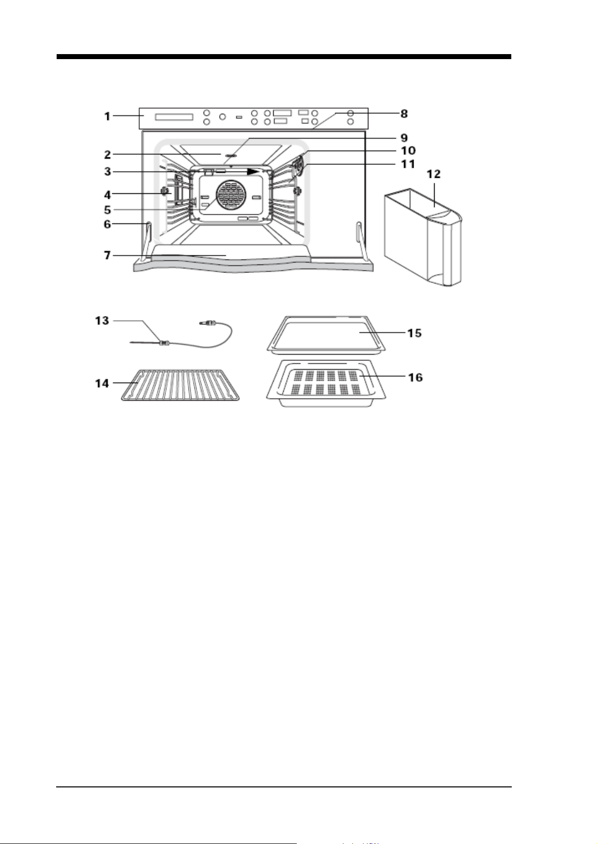
3.4 EKDG 6800.0
1 Control and display elements 9 Oven temperature sensor
2 Oven ventilating system 10 Female connector for the roast thermometer
3 Steam inlet 11 Rack levels
4 Illumination 12 Water tank
5 Hot air blower 13 Roast thermometer
6 Door seal 14 Roasting grid (2 grids)
7 Appliance door 15 Original baking tray made of stainless steel
8 Air vent slit 16 Perforated cooking pan
For internal use only
H3-72-01 17
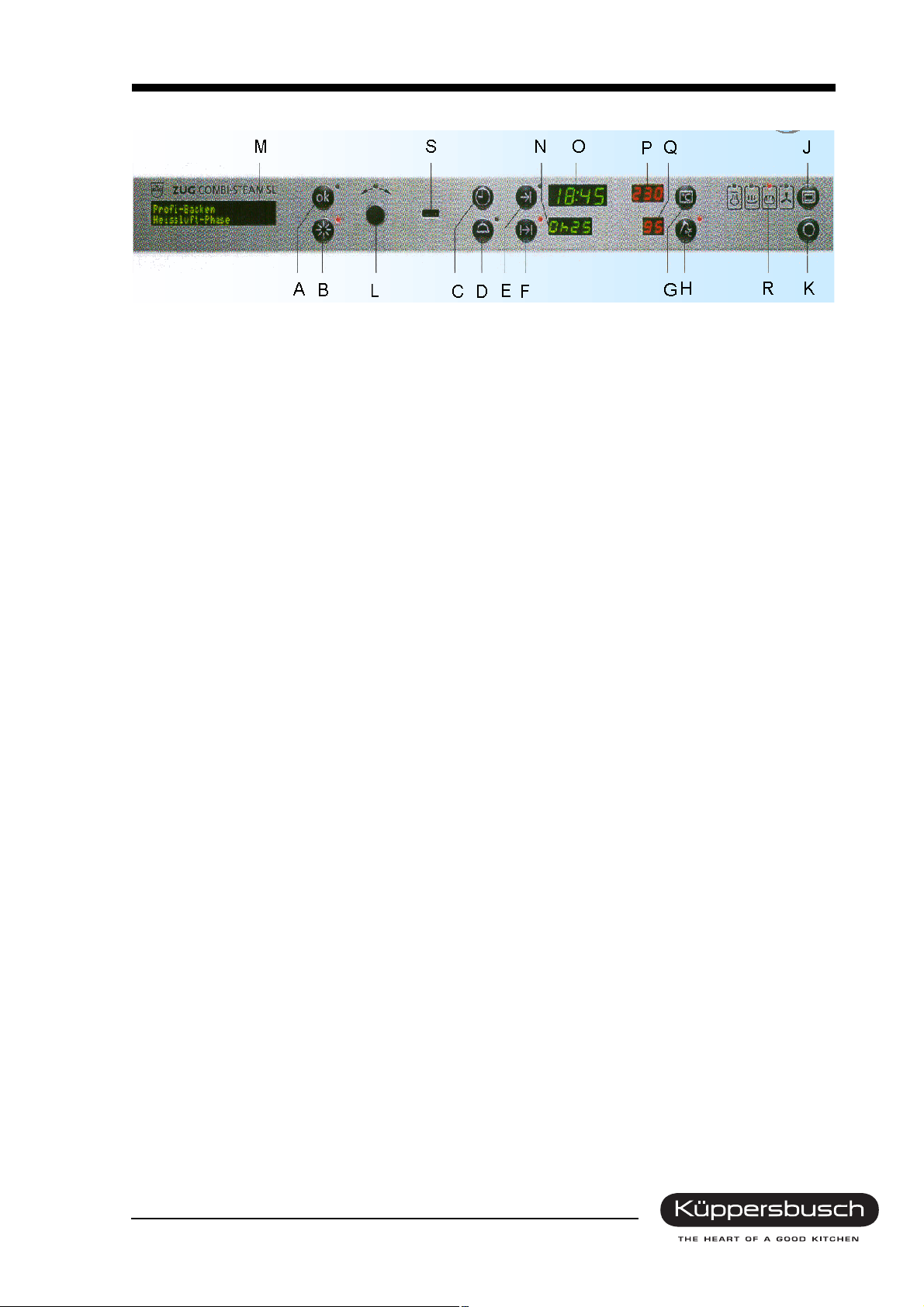
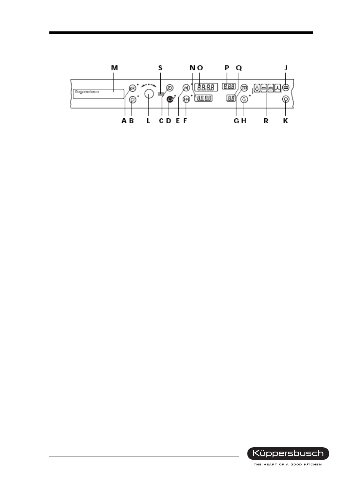
3.4.1 Control elements
Buttons
A ok
B Illumination
C Time
D Timer
E Switch-off time
F Operating time
G Oven temperature
H Food probe temperature
J Operating mode
K Switching off
L Adjusting knob
with a control light
with a control light
with a control light
with a control light
with a control light
with a control light
with a control light
Displays
M Clear text display
N Operating time / Timer
O Time / Switch-off time
General information on operation
Settings can be made with the knob after the button for the respective mode of operation has been
pressed.
Once the button has been pressed settings can be changed for a short time.
The selected mode can also be started up immediately with the button if you do not wish to wait until the
setting time has lapsed after making the previous setting.
P Oven display
Q Food probe temperature
R Operating mode symbol
S Draught eye
For internal use only
18 H3-72-01
3.4.2 Appliance parts
4
3
Empty
Suction
8
1
3.4.3 Technical data
Appliance dimensions Oven dimensions Niche dimensions
Height
Width
Depth
Weight
Maximum load
37.8 cm 25.0 cm 38.0 cm
59.6 cm 35.9 cm at least 58.0 cm
56.7 cm 39.0 cm at least 55.0 cm
5
6
2
1 Water tank
2 Swivel arm
3 Steam generator
4 Steam
5 Limestone sensor
6 Hot air
7 Oven cavity
8 Climatic sensor
35 kg
2kg
7
Electrical connection
Connection voltage 230V ~50 Hz
Power Connected wattage 3.5 kW
Electrical voltage
16 A
Heating power
Hot air power
Steam generator 1.2 kW
Floor heater
2.2 kW
0.14 kW
Safety concept
The appliance will be monitored by the electronic control system for as long as it is supplied with power.
Any faults which occur will be shown in the clear text display.
For internal use only
H3-72-01 19
For EKDG 6800.0-75
Electric connection 230~/16 A with a single phase socket
system (see illustration).
Due to the mains cable of 3.5 kW the appliance will need
to be protected by a 16 A fuse. The appliance must be
wiring as shown on the illustration.
New electronic system features
• Completely new computer component (not
compatible with 756/EKDG 6800.0)
• No power monitor circuit (suitability for export)
• Brightness of the clock display improved
blue
brown
black
• No longer any phase for the exhaust fan (only relay)
• The boiler heater is activated by a relay instead of
with a triac
• Completely new operating element (not compatible
with 756/EKDG 6800.0)
• Completely new operating element and text display
(not compatible with 756/EKDG 6800.0)
• New rotary encoder with a button (more stable and
better)
yellow-green
yellow-green
brown
blue
For internal use only
20 H3-72-01
3.5 EKDG 6800.1 / EKDG 6800.2
1 Control and display elements 9 Steam inlet
2 Oven ventilating system 10 Female connector for the roast thermometer
3 Illumination 11 Supporting grids
4 Hot air blower 12 Water tank
5 Door seal 13 Food probe
6 Appliance door 14 Roasting grid (2 grids)
7 Air vent slit 15 Stainless steel baking tray
8 Oven temperature sensor 16 Perforated cooking pan
17 Water filters (3 filters)
For internal use only
H3-72-01 21
3.5.1 Control elements
Buttons / adjusting elements Displays
A Illumination O Clear text display
B Oven/food probe temperature P Temperature
C Operating mode Q Time / cooking time and timer
D Adjusting knob R Draught eye
ETimer
F Operating time / Switch-off time
G Switching off
Symbols
H Oven temperature L Operating time
I Food probe temperature M Switch-off time
J Operating mode N Time
KTimer
For internal use only
22 H3-72-01
3.5.2 Appliance parts
4
3
Emptying
Suction
8
1
3.5.3 Technical data
Appliance dimensions Oven dimensions Niche dimensions
Height
Width
Depth
Weight
Maximum load
Electrical connection
37.8 cm 25.0 cm 38.0 cm
59.6 cm 35.9 cm 58.0 cm min.
55.1 cm 39.0 cm 55.0 cm min.
5
6
2
1 Water tank
2 Swivel arm
3 Steam generator
4 Steam
5 Limestone sensor
6 Hot air
7 Oven cavity
8 Climatic sensor
47 kg
2 kg
7
Connection voltage 230V-240V ~50 Hz
Power Connected wattage 3,5 kW
Electrical voltage
16A
Heating power
Hot air power
Steam generator 1.4 kW
Floor heater
1.9 kW
0.14 kW
Safety concept
The appliance will be monitored by the electronic control system for as long as it is supplied with power.
Any faults which occur will be shown in the clear text display.
For internal use only
H3-72-01 23
4. Installation
4.1 Safety instructions for technicians
• Local electricity suppliers’ statutory regulations and conditions for connection are to be fully observed.
• The appliance must be disconnected on being connected, on carrying out repairs and when changing
a bulb. Disconnect the shock-proof plug or switch off the safety fuse.
• Full protection against accidental contact must be guaranteed on instalment.
• The appliance is ready to be plugged in and may only be connected to a shockproof socket which
has been installed according to specifications. Plug installation, the exchanging of terminal wires and
zero conductors or replacement of the connecting wire may only be carried out by a qualified
electrician under observance of the relevant regulations.
• Should the plug not be accessible subsequent to installation, a universal disconnection device with a
contact clearance of at least 3 mm must be available at the installation point in order to fulfil relevant
safety regulations.
• The built-in cupboard for the combi-steam cooker must be heat resistant up to 100 °C. This applies
in particular to veneers, overlapping edge bands, plastic surfaces, adhesives and varnishes.
Adjacent kitchen unit front panels must be heat resistant up to at least 70 °C.
• It is essential to instal the appliance horizontally on a board which is level and stable. The board may
not bend.
• Should the kitchen unit not be attached to the wall it must be screwed on with a standard commercial
angle.
4.2 Installation EDG / EKDG
4.2.1 in a suitable niche
For internal use only

24 H3-72-01
in a standard niche (with a levelling panel, ZUB. 736 (in preparation)
4.2.2 in kitchen units
Installing the appliance
• Put the plug into the socket.
• If “U2” is indicated on the display, the plug must be
turned. Should this not be possible, a qualified
electrician must exchange the zero conductor and the
terminal wire in the socket.
• Push the appliance right into the unit niche. On doing so,
make sure that the appliance connection is not squeezed!
Attaching the appliance
• Open the oven door and screw the appliance to the
kitchen unit with the screws supplied – screw them in at an
angle – from the inside to the outside.
For internal use only
H3-72-01 25
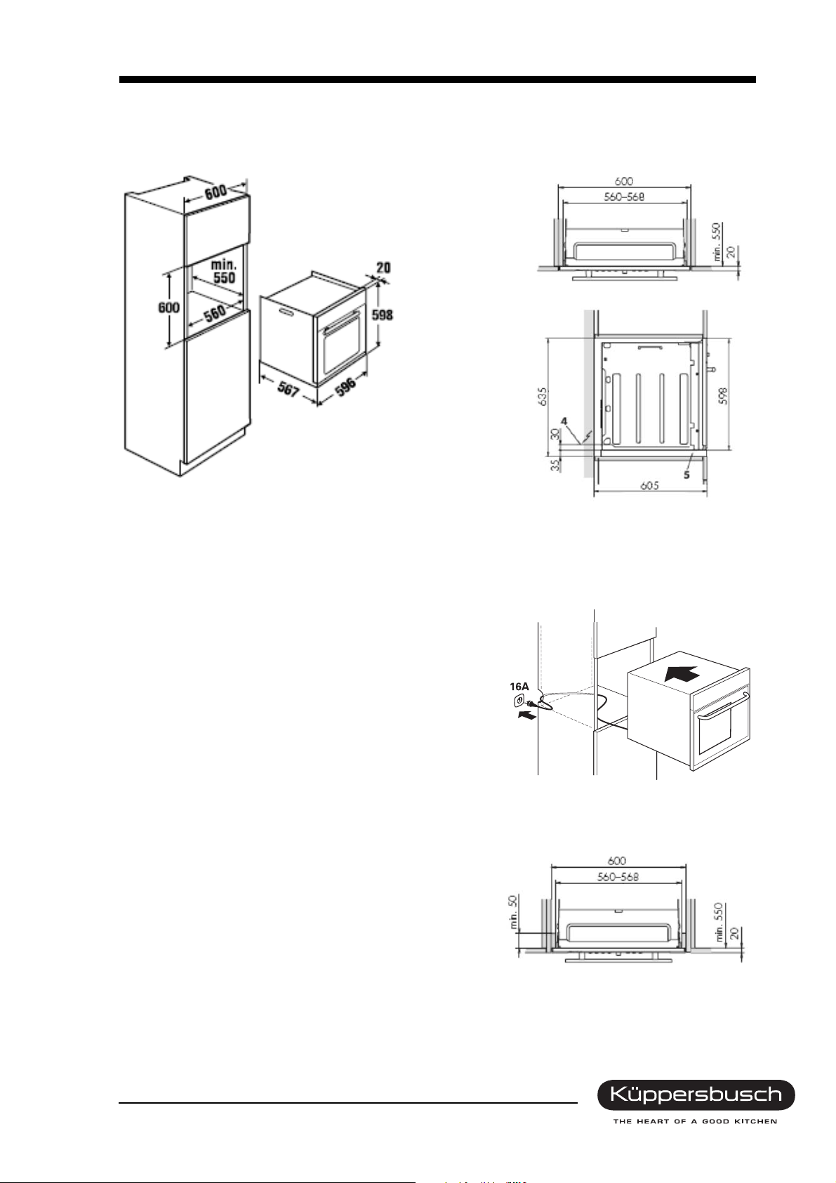
4.3 Installation EEBD 6600.0
4.3.1 in a suitable niche
Fitted installation
Niche
Installation 5/6 niche SMS
4 Electric connection cable
5 Adapter frame
4.3.2 in kitchen units
Installing the appliance
• Put the plug into the socket.
• If “U2” is indicated on the display, the plug must be
turned. Should this not be possible, a qualified
electrician must exchange the zero conductor and the
terminal wire in the socket.
• Push the appliance right into the unit niche. On doing so,
make sure that the appliance connection is not squeezed!
Niche
Niche
Appliance
Attaching the appliance
• Open the oven door and screw the appliance to the
kitchen unit with the screws supplied – screw them in at an
angle – from the inside to the outside.
For internal use only
Sunken installation
Niche
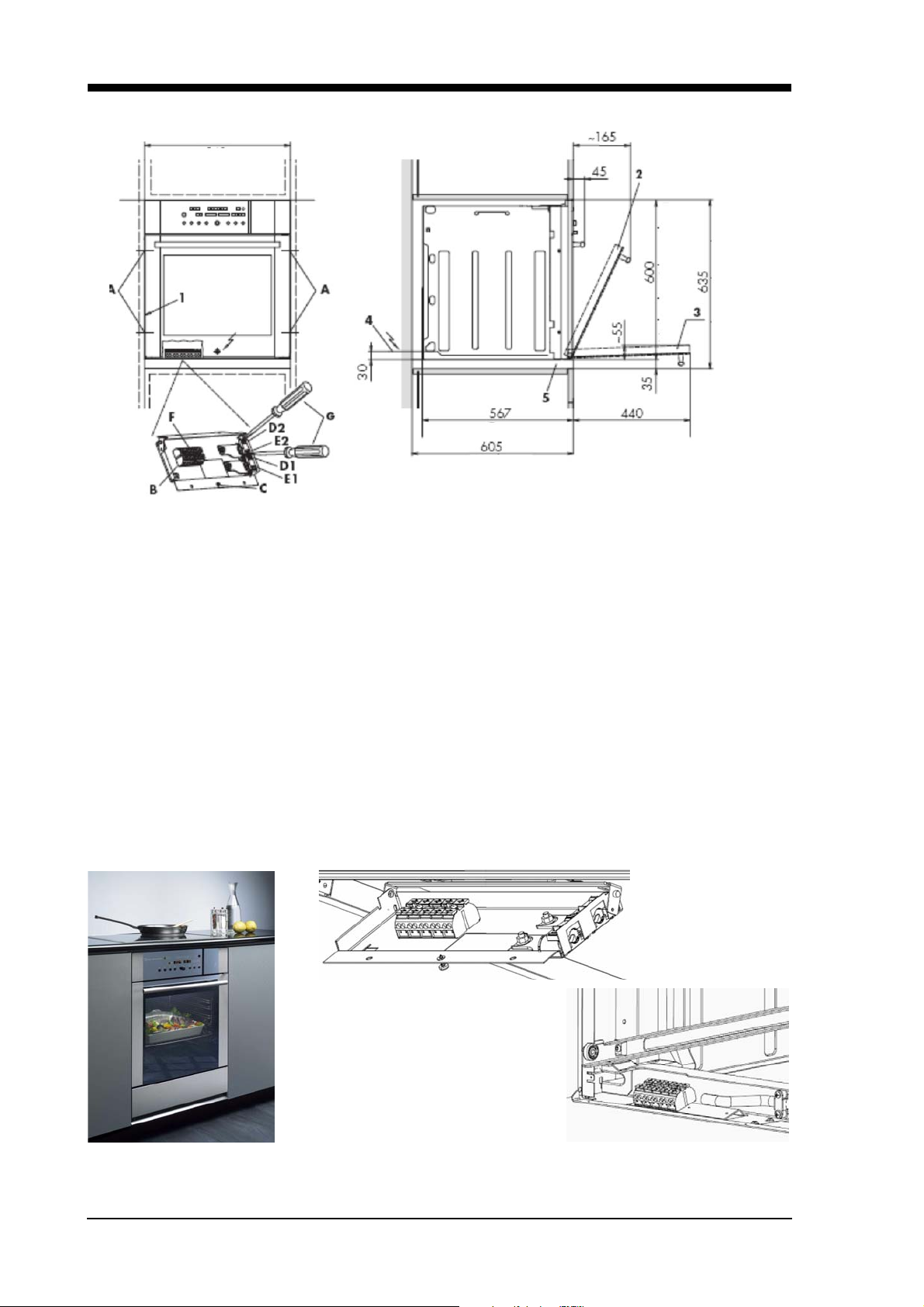
26 H3-72-01
Open the snap fastener of the strain relief with a screwdriver.
550 Niche
548 Appliance
598 Appliance
Niche without an adapter frame
Appliance
Niche
Niche with an adapter frame
1 Model identification plate 4 Electric connection cable
2 Exhaust air position 5 Adapter frame
3 Appliance door open
1. Push the appliance up to approx. 19 cm into the niche. Caution! Risk of tipping over!
2. Open the terminal box with the screw and swing it down.
3. Pull the connection cable from where it protrudes from the wall through hole D1. Ensure strain
relief by fastening the snap fastener. Connect to the terminal in accordance with connection regu-
lations.
4. Swing up the terminal box again and fasten with the screw.
5. Push the appliance into the niche until the front is flush and fasten it on the sides with the four chip
boardsenclosed.
4.3.3 in a bottom unit
Connection direct to the appliance (pat. pend.)
For internal use only

H3-72-01 27
4.3.4 Combined connection
Important!
When connecting a second appliance (e.g. a cooking zone) the electrical supply line
must be dimensioned accordingly and protected by fuse. Observe installation norm
DIN!
When connecting a second appliance the connection cable of this
appliance must be guided separately into the opening D2 and must
be secured with strain relief E2. The connection cable of the second
appliance must be guided direct along the rear wall of the niche and
then to the combined connection (excessive cable lengths may not
be laid between the appliances.
Version 6/6 appliance
Supply line
Second appliance
Version: short appliance
Electric connections
yellow/green
Separate duct and separate
strain relief at the front
Mains connection cable
Connection cable for the second appliance
Error messages
Power supply faults are shown as follows
U1 PE mains connection faulty U4 L2 mains connection faulty
U2 N mains connection faulty U5 L2 mains connection faulty (L1 and L2 identical)
U3 L1 mains connection faulty
For internal use only
28 H3-72-01
5. EDG / EKDG appliance components
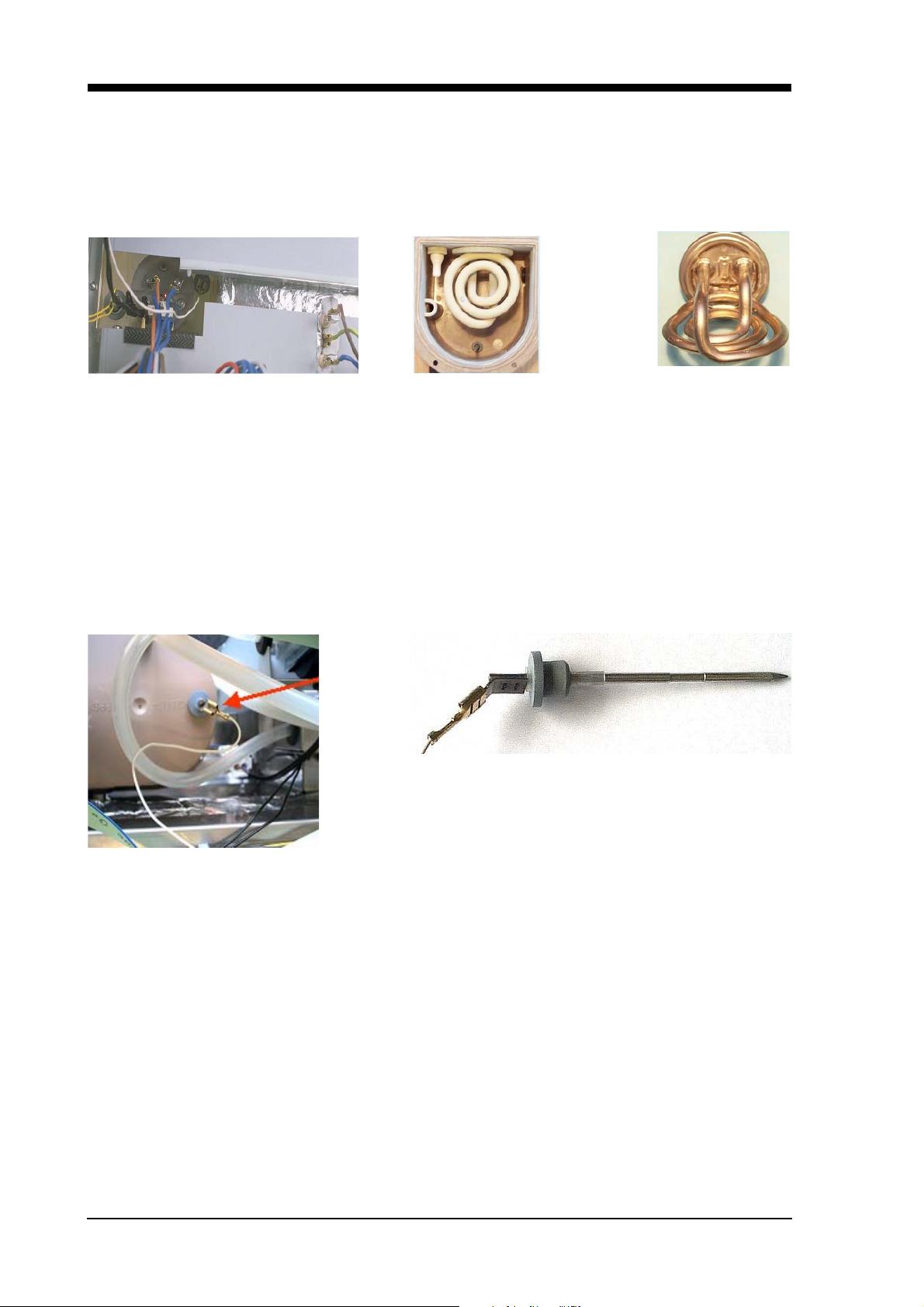
5.1 Limestone sensor
Limestone sensor and heat protection NTC 25°C/10 kW
Heater installed Heater with limestone Heater dismounted
The amount of scaling is determined as two measured variables, namely the temperature of the heating
spiral and the conductance of the level sensor. Scaling on the tubular heating element of the evaporator
increases the readings taken on the heating spiral temperature sensor. Scaling is tolerated up to a
maximum degree with some difference above the boiling temperature of the water. Until the clear text
display gives an indication the permissible maximum degree of scaling must have been exceeded for
some time (5 times or approx. 200 operating hours).
5.2 Level sensor (point gauge)
Scaling, initially primarily at the top of the level sensor, lowers the gauged conductance level of the water.
Scaling is tolerated up to a maximum degree of conductance. Until the clear text display gives an
indication, the permissible maximum degree of scaling must have been exceeded for some time (5 times
or approx. 200 operating hours).
If one of the measured variables exceeds the maximum permissible reading, the clear text display will
indicate “descale”.
Once the indication has appeared the appliance can continue to operate with steam. However, the effect
of the evaporator is minimized when scaling increases.
Since soft water or a domestic descaling device may result in the limestone sensor not actuating, after
a certain number of hours of operation and for reasons of hygiene the clear text display will require the
user to descale the system.
In order to be able to recognise the water level in the evaporator by means of the level sensor, the
average result of 80 readings during a period of 2 sec. (software) is deducted.
For internal use only
H3-72-01 29
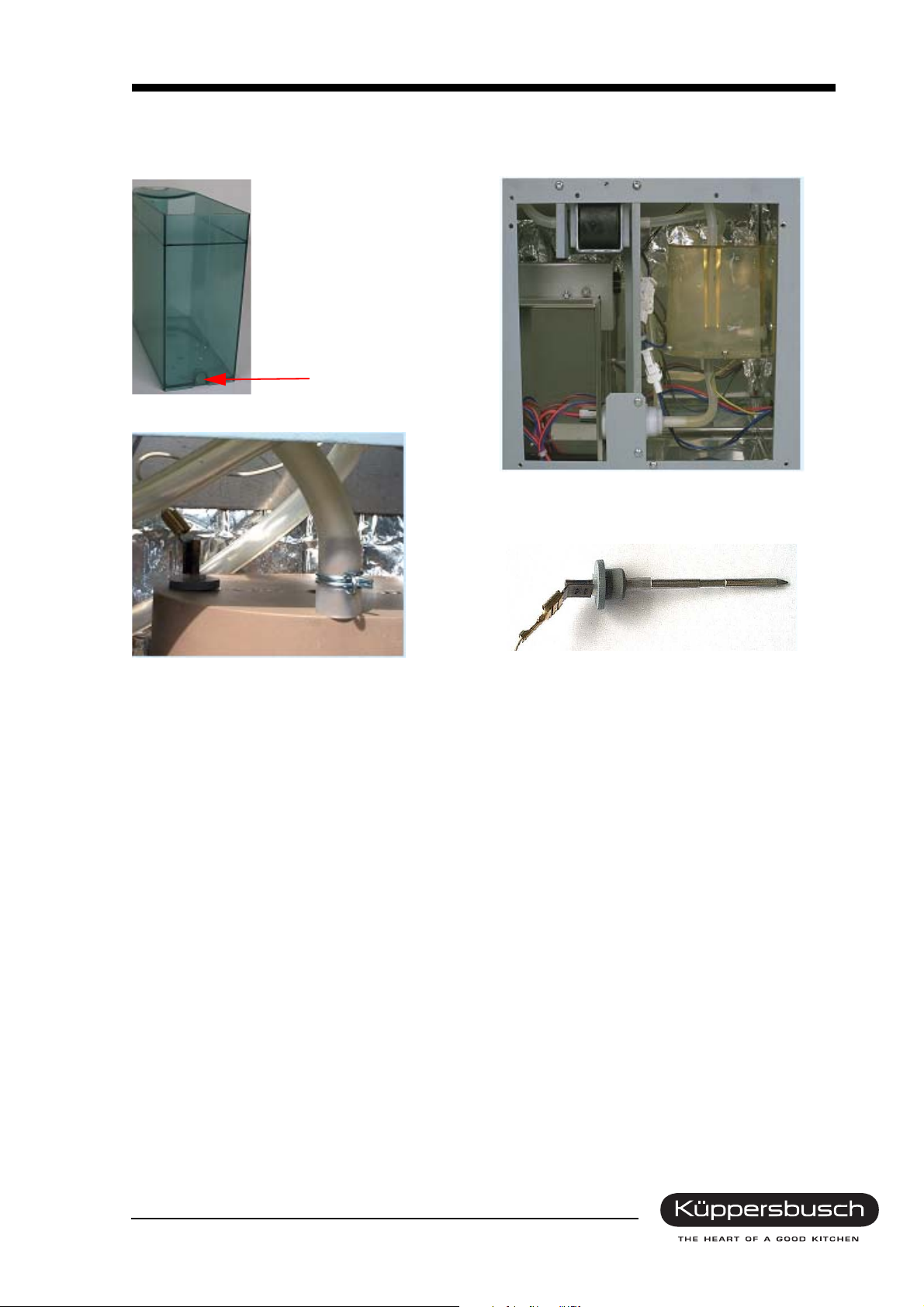
5.3 Water system
Water tank, 1.25 litres
Ignition solenoid
For internal use only
30 H3-72-01
5.3.1 Water inlet
If, during a certain period, no water is recognised in the evaporator on filling, the supply of water is
discontinued and the clear text display will indicate “Fill up with water”. The following may be the cause
of a faulty water supply:
• no water or too little water in the water tank
• a faulty supply pump or hoses which are kinked or defect
• a defect or scaled level sensor
5.3.2 Emptying
In the case of all of the operating modes, emptying is carried out automatically after the OFF button has
been pressed or after the cooking time has expired or after completion of steam dissipation, apart from
during pure hot air operation.
Firstly the water temperature in the evaporator is determined, and if this exceeds a certain level, water
is then pumped out of the water tank into the evaporator by means of the supply pump, up to level
recognition by the level sensor, plus a certain follow-on time. This procedure is carried out for the
purpose of thermal protection of the discharge pump. Pumping off the water with the discharge pump is
also regulated by means of level recognition by the level sensor and a certain follow-on time. Should
emptying of the evaporator not be carried out within this maximum period of time, two more attempts will
be made. Should it still not be possible to pump off water, the clear text display will indicate “contact F8
service” (emptying faulty).
An essential marginal condition for pumping off the water in the evaporator is a water temperature below
a certain level. Should it not be possible to cool the water in the evaporator down to this temperature –
because there is insufficient water in the water tank or because the water in the water tank is too warm
– the water will not be pumped off. It will only be pumped off when it has cooled itself down to this
temperature (this may well take more than 30 minutes!). The appliance is still ready for operation during
this period. During this cooling-down process, the clear text display will indicate “water is being pumped
off”.
Should, shortly before completion of steam operation, a completely full water tank be supplied with more
water, the water tank may become overfilled on pumping off.
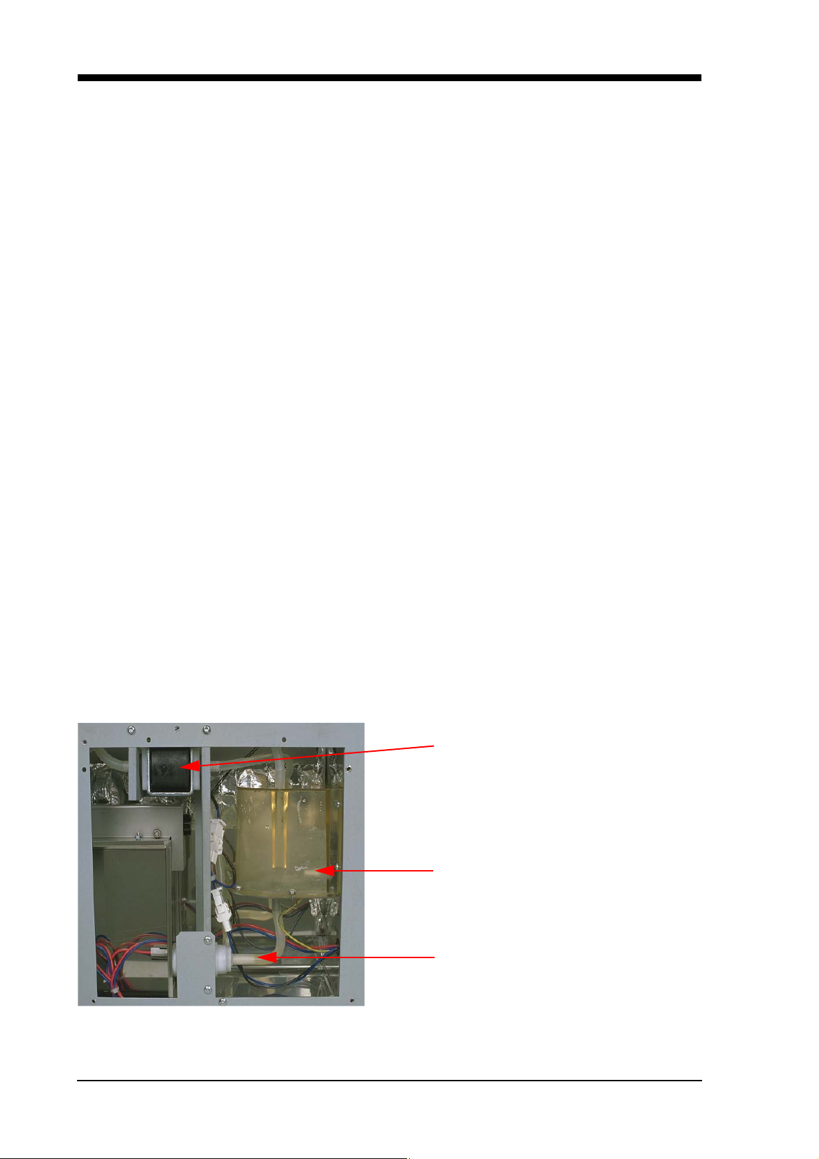
Water pump “Cotec” 230 V~ (lighting )
Sensor for altitude adjustment and water
NTC 25°C/100 kΩ
Water pump “Hella” 12 V = (empty)
For internal use only
 Loading...