

Page 1
28130 AMP-Ständer
- Für Bühne, Studio und Proberaum
- Tragkraft: bis 35 kg
- stabil und standfest
- flexibel einstellbar
- platzsparend in der Anwendung und beim Transport
- mit Teleskoprohr und Anschlußgewinde (3/8" u. 5/8") für Schwenkarm
SICHERHEITSHINWEISE
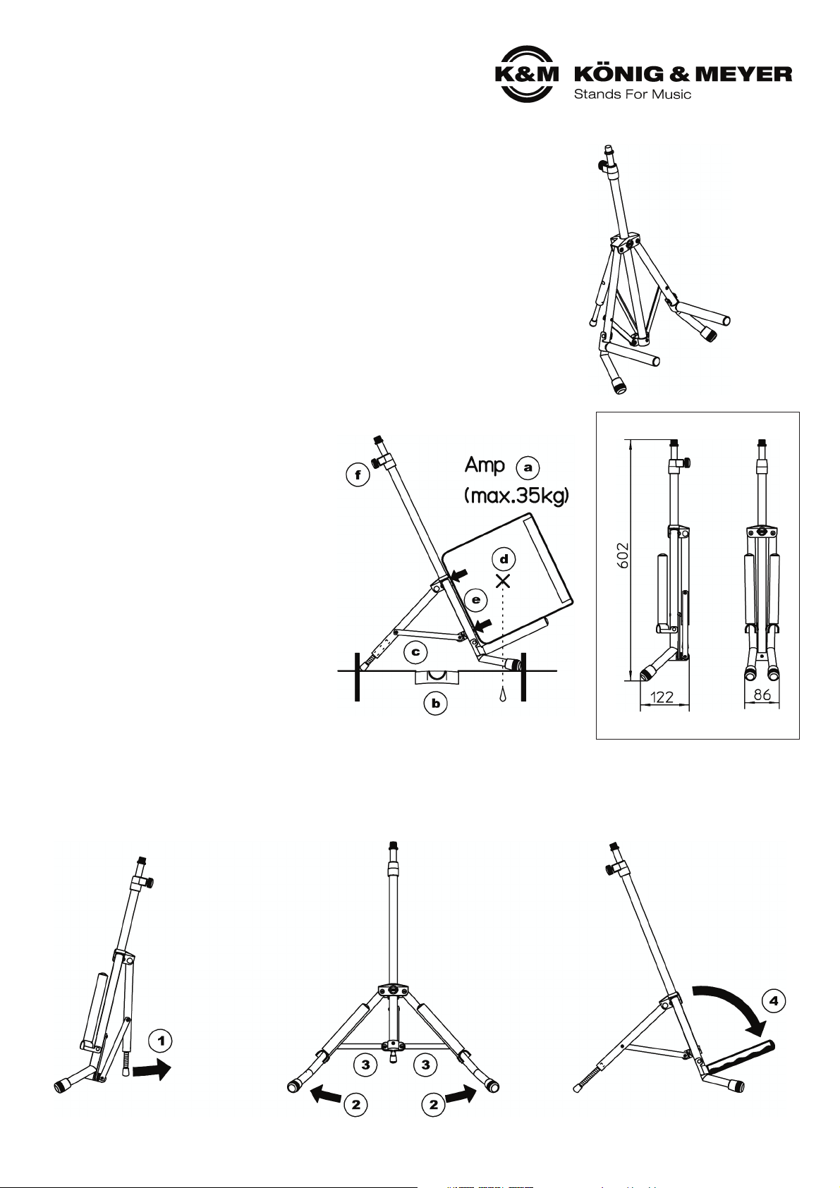
a. Tragkraft: max. 35 kg
b. Der Untergrund muß tragfähig und eben sein.
c. Die Füße des Stativs sollten so weit wie
c. möglich auseinandergezogen werden, bis die
c. Fußstreben annähernd waagerecht stehen.
d. Die Größe des Amp muss so bemessen sein,
d. dass sein Schwerpunkt sich innerhalb der
d. Füsse des aufgestellten Statives befindet.
e. Der Amp soll mit dem Rücken an den
e. Stativrohren anliegen.
f. Verschraubungen sind fest, aber nicht
f. überfest anzuziehen.
g. Der Amp muss vom Stativ abgenommen werden,
g. bevor man Änderungen an der Auflagenbreite
g. und Neigung vornimmt
h. Die Möglichkeit das Stativ zusammenzuklappen
h. oder zu verstellen, birgt naturgemäß die Gefahr
h. des Einklemmens;
h. umsichtige und aufmerksame Handhabung bei
h. Aufbau, Betrieb und Abbau sind daher unverzichtbar.
AUFSTELLANLEITUNG
Der Aufbau des 28130 Amp-Ständers ist sehr einfach. Es ist bereits vormontiert und muss lediglich in Position gebracht werden.
1 Zunächst hinteren Stützfuß leicht aufklappen. 2 anschließend Vorderfüße auseinanderziehen bis... 4 Auflagen nach vorne klappen.
3 ...Fußstreben in etwa waagerecht stehen.
Vielen Dank, dass Sie sich für dieses Produkt entschieden haben. Diese Anleitung
informiert Sie über alle wichtigen Schritte bei Aufbau und Handhabung. Wir empfehlen,
sie auch für den späteren Gebrauch aufzubewahren.
TRANSPORTSTELLUNG
Page 2

AMP-STÄNDER EINSTELLEN
A. AUFLAGENBREITE (AMP vorher entnehmen)
4 Maximale Auflagenbreite ist gegeben bei
4 waagerechter Stellung der Streben.
5 Kleinere Auflagenbreiten erreicht man durch
5 Absenken des Grundrohres.
5 HINWEIS:
5 Die Reduzierung der Auflagenbreite führt auch
5 zur geringeren Fußabständen.
5 Bitte Standfestigkeit der Installation prüfen.
B. NEIGUNGSWINKEL DER AUFLAGEN (AMP vorher entnehmen)
6 Das hintere Fußende ist als
6 Gewindestange ausgeführt.
6 Durch Drehen an dieser
6 Stange kann der Neigungs-
6 winkel des Stativs und damit
6 der Auflagen effektiv
6 verändert werden.
7 Eine weitere Verstellung
7 des Neigungswinkels ergibt
7 sich durch die Änderung der
7 Fußstellung, wobei dies auch
7 zu Lasten der Standfestigkeit
7 gehen könnte. Deshalb ist
7 diese Variante eher für
7 kleine Korrekturen geeignet.
C. TELESKOPARM FÜR MIKROANSCHLUSS (AMP nicht entnehmen)
08 Mit 3/8" Anschlußgewinde und 5/8"-Reduziergewinde.
09 Das Auszugrohr kann um bis zu 420 mm stufenlos
90 ausgefahren werden: Klemmschraube lösen,
90 Auszug einstellen, Schraube wieder anziehen.
10 Mikrofonarm anschrauben.
PRÜFEN, INSTANDHALTEN, REINIGEN
- Schonender Umgang mit dem Stativ erhält die Teleskopierbarkeit,
- die Tragkraft und die Sicherheit der Installation
- Bei Wartungsarbeiten -stets im unbelasteten Zustand-
- auf evtl. Gefährdungen achten (Einklemmen, Anstoßen, Kippen)
- Zur Reinigung und Pflege am besten ein leicht feuchtes Tuch und
- ein nicht scheuerndes Reinigungsmittel benutzen
BENUTZERHINWEISE /FUNKTIONEN
TECHNISCHE DATEN
Material
Rohre, Streben, Gewinde: Stahl
Schellen: Polyamid (PA)
Parkettschoner, Auflagen: TPE
Verbindungselemente: Stahl vern./verz.
Abmessungen
Höhe: 570 - 990 mm
Standfläche: max. 430 x 530 mm
Packmaß, kg B x T x H: 122 x 86 x 602 mm, 2,0 kg
Verpackung Polybeutel
Zubehör
(optional)
Schwenkarme z.B. 211, 211/1, 21140
Mikrofonklammern 85035, 85050, 85055, 85060
Tragetasche 10811
KÖNIG & MEYER GmbH & Co. KG
Kiesweg 2, 97877 Wertheim, www.k-m.de
28130-011-55 Rev.07 03-80-791-00 3/14
Schwenkarme - z.B. 211
Page 3

28130 AMP-Stand
- For Stage, Studio and Rehearsal Rooms
- Load bearing weight: up to 35 kg
- Solid and stable
- Flexible adjustment
- Space saving both when using and transporting the stand
- With a telescope tube and connection thread (3/8" and 5/8") for swivel arms
SAFETY NOTES
a. Load bearing weight: max 35 kg
b. The floor must be load bearing and even.
c. The stand legs should be placed as far apart
c. as possible, until the leg struts are as level
c. as possible.
d. The size of the amp must be such that the
d. weight is centered within the leg area.
e. The back of amp is to rest on the
e. stand tubes.
f. Tighten the screws, but ensure that the
f. screws are not over-tightened.
g. The amp must be taken off of the stand
g. before adjustments are made to the base-width
g. and angle.
h. Beware, collapsing or adjusting the stand
h. may result in the risk of pinching ones fingers.
h. Careful and attentive handling during setup,
h. operation, disassembly is indispensable.
SET UP INSTRUCTIONS
Setting up the 28130 Amp Stand is very easy. It comes pre-assembled and only needs to be placed in the proper position.
1 First flip open the support leg. 2 Then pull the front legs apart until... 4 Flip the support arms forward.
3 ...the foot struts are as level as possible.
Thank you for choosing this product.
The instructions provide directions to all of the important set up and handling steps.
We recommend you keep these instructions for future reference.
Transportation Position
Page 4

AMP STAND ADJUSTMENTS
A. SUPPORT ARM WIDTH (First remove AMP)
4 The maximum support arm width is determined
4 when the struts are as level as possible.
5 Smaller support arm widths can be attained by
5 lowering the base tube.
5 NOTE:
5 The reduction of the support arm width also
5 results in smaller distances between the legs.
5 Please check the stability of the installation.
B. ANGLE OF THE SUPPORT ARMS (First remove the AMP)
6 The back leg is
6 a threaded rod.
6 By turning this rod the angle
6 of the stand
6 and as such the
6 support arms can
6 be adjusted.
7 An additional adjustment of
7 the angle is possible by
7 adjusting the positioning
7 of the legs, however this
7 can negatively affect stand
7 stability. This is why this
7 option is more suited to
7 smaller adjustments.
C. TELESCOPE ARM FOR MICROPHONE CONNECTION
C. (Do not remove the AMP)
08 With 3/8" connection thread and 5/8" reducer thread.
09 The extension tube can be extended up to 420mm:
90 loosen the clamp screw, extend the tube, tighten the screw.
10 Screw on the microphone arm.
USAGE NOTES / FUNCTIONS
TECHNICAL DATA
KÖNIG & MEYER GmbH & Co. KG
Kiesweg 2, 97877 Wertheim, www.k-m.de
28130-011-55 Rev.07 03-80-791-00 3/14
Boom arm - z.B. 211
CHECK, MAINTENANCE, CLEANING
- Careful use of the stand maintains the use of the telescope and the
- load bearing functionality of the stand, as well as the safety of the installation
- Perform workstation maintenance only without the amp on the support arms
- and watch for eventual risks (pinched fingers, impact, the stand falls over)
- To care for the product use a damp cloth and a non-abrasive cleaning agent
Material
Tubes, Struts, Threads: Steel
Brackets: Polyamid (PA)
End Caps, Support Arms: TPE
Connection Elements: Steel nickel coated / galvanized
Dimensions
Height: 570 - 990 mm
Stand area: max. 430 x 530 mm
Packaging
dimensions, kg
W x D x H: 122 x 86 x 602 mm, 2.0 kg
Packaging Poly-Bag
Accessories
(optional)
Microphone Arms: e.g. 211, 211/1, 21140
Microphone Clamps 85035, 85050, 85055, 85060
Carrying Case 10811
 Loading...