

Page 1

26740 Monitorstativ
- schlankes, praktisches Stativ zur Positionierung von Monitoren
- Tragkraft: max. 35 kg zentrische Last
- auch zum direkten Befestigen von Monitoren mit 3/8" Gewindeanschluß
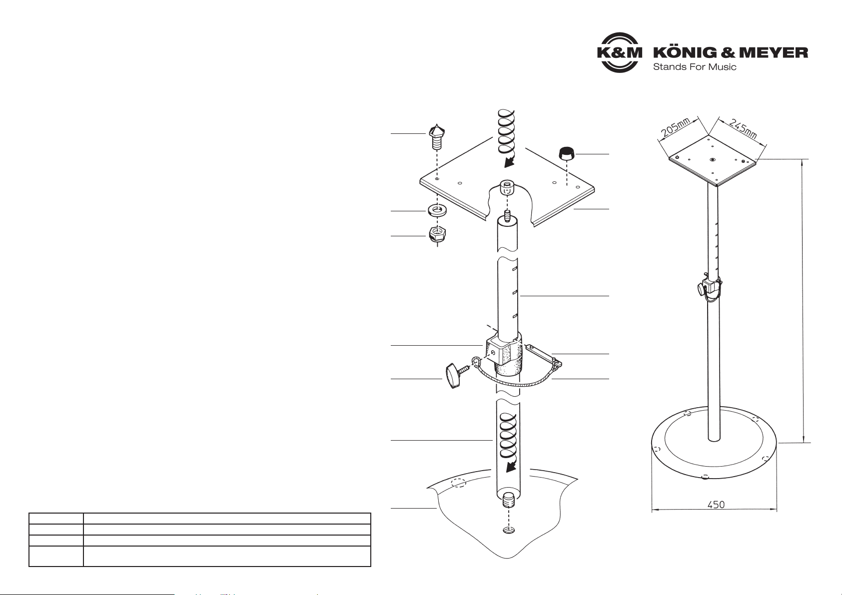
- die Auflageplatte (245 x 205 mm) kann wahlweise mit 4 Gumminoppen
- oder 4 Gewindespitzen zur Aufnahme des Monitors bestückt werden
- höhenverstellbar von 950 bis 1430 mm, Fußkreis 450 mm, Eigengewicht 9,9 kg
SICHERHEITSHINWEISE
- Bodenplatte 1 mit Vorsicht handhaben, insbesondere bei Montage nicht fallen lassen.
- auf feste Schraubverbindungen achten.
- Sicherungsschiene 9 muß stets installiert sein.
- vor Einstellung der Höhe oder Wechsel des Standortes den Monitor abnehmen.
- Messingspitzen 7 ohne Monitor stellen ein Verletzungsrisiko dar.
- bei Nichtbenutzung demontieren oder Schutzmaßnahmen treffen.
- Stativ nur für tragfähigen und ebenen Untergrund zulässig.
- Bei Publikumsverkehr auf ausreichend Abstand achten.
AUFBAUANLEITUNG
- Bodenplatte 1 mit Filzschonern nach unten auslegen.
- Grundrohr 2 mit Gewinde M20 in Bodenplatte einschrauben.
EINSTELLEN DER HÖHE
- Auszugrohr herausziehen 10
- Sicherungsschiene 9 mit Nocke oben bis zum Anschlag durch passenden Schlitz des
- Auszuges 10 schieben. Auszug wieder ablassen bis Sicherungsschiene auf beiden Seiten der
- Spannschelle 4 aufliegt.
- Klemmschraube 3 durch Schlaufe der Kordel 8 stecken und in Spannschelle 4 festschrauben.
- Auflageplatte 11 auf Gewinde des Auszugrohres 10 schrauben.
UNTERLAGEN FÜR MONITOR
- Wahlweise 4 Messingspitzen 7 oder 4 Gumminoppen 12 einsetzbar.
Messingspitzen: Gewinde von oben durch Bohrungen führen (8 Bohrungen zur Wahl) und mittels
Messingspitzen: U-Scheiben 6 und Sicherungsmuttern 5 an der Auflageplatte festschrauben.
Gumminoppen: selbstklebend; Schutzfolie abziehen und an gewünschter Stelle auf Platte kleben.
1
2
3
4
5
6
7
8
9
10
11
12
min. 940/max. 1430 mm
Vielen Dank, dass Sie sich für dieses Produkt entschieden haben. Diese Anleitung informiert
Sie über alle wichtigen Schritte bei Aufbau und Handhabung. Wir empfehlen, sie auch für den
späteren Gebrauch aufzubewahren.
PRÜFEN, INSTANDHALTEN, REINIGEN
- Bei Wartungsarbeiten -stets im unbelasteten Zustand- auf evtl. Gefährdungen achten
- (Messingspitzen, Einklemmen, Anstoßen, Kippen)
- Zur Pflege ein leicht feuchtes Tuch und ein nicht scheuerndes Reinigungsmittel benutzen
FEHLERSUCHE (F) und BESEITIGUNG (B)
F: Stativ bzw. Auszugrohr wackelt B: Bodenunebenheiten beseitigen
F: Stativ bzw. Auszugrohr wackelt B: Verschraubungen nachziehen
F: Stativ bzw. Auszugrohr wackelt B: Sicherungsschiene prüfen
TECHNISCHE DATEN / SPEZIFIKATIONEN
Material Bodenplatte: Gußeisen, Rohrkombination, Auflageplatte: Stahl, Spannschelle: PA
Traglast max. 35 kg zentrische Last
Abmessungen Bodenplatte ø 450 mm, Höhe: 950-1430 mm, Auszugrohr ø 35 mm
Zubehör
(optional)
Tragetaschen: K&M 21421 (Rohre), K&M 26751 (Bodenplatte)
KÖNIG & MEYER GmbH & Co. KG
Kiesweg 2, 97877 Wertheim, www.k-m.de
26740-000-55 Rev.07 03-80-827-00 3/13
Page 2
26740 Monitor Stand
- slim and practical stand for positioning monitors
- max. load: 35 kg central load capacity
- monitor can also be attached directly with a 3/8" thread connection
- support plate (245 x 205 mm) can be fitted either with 4 rubber studs or
- 4 threaded nibs to hold the monitor in place
- height can be adjusted from 950 to 1430 mm, footprint 450 mm, own weight 9.9 kg
SAFETY NOTES
- Take care when handling the base plate 1, do not allow to fall when assembling.
- Ensure all screw connections are tight.
- Safety catch 9 must always be in place.
- Always remove the monitor before adjusting the height of the stand or moving to another place.
- When the monitor has been removed, there is a risk of injury from the exposed brass nibs 7.
- When not using the stand, either dismantle it or take suitable protective measures.
- Stand is only suitable for even and firm ground.
- Ensure there is sufficient clearance at public conventions.
ASSEMBLY INSTRUCTIONS
- Place the base plate 1 on the ground with the felt protectors on the underside.
- Attach the base shaft 2 to the base plate using thread M20.
TO ADJUST THE HEIGHT
- Lift the extension shaft 10 slightly
- Insert safety catch 9, with the tappet facing upwards, through a slit in the extension shaft 10 at
- the required height until it reaches the stop position. Lower the extension shaft until the safety
- catch is visible on both sides of the clamping collar 4.
- Insert the clamping screw 3 through the loop in the cord 8 and screw to the clamping collar 4.
- Connect the support plate 11 to the thread of the extension shaft 10.
UNDERLAY FOR MONITOR
- Either 4 brass nibs 7 or 4 rubber studs 12.
- Brass nibs: insert thread from above through the drill hole (8 holes to chose from) and connect
- Brass nibs: tightly to the base plate using a washer 6 and locking nut 5.
Rubber studs: self-adhesive; remove protective foil and attach at required place.
1
2
3
4
5
6
7
8
9
10
11
12
min. 940/max. 1430 mm
Thank you for choosing this product. This instruction manual informs you about the important
steps to set up and handle the product. We recommend to keep the manual in a separate place
for a possible later use.
INSPECTION, MAINTENANCE, CLEANING
- For maintenance purposes, remove the monitor and be aware of potential hazards (brass nibs,
- pinching, knocking, tipping) and take suitable precautions.
- For cleaning purposes utilise a slightly damp cloth with a non-abrasive cleaning solvent
FAULT-FINDING (F) and REPAIR (R)
F: Stand or extension shaft wobbles R: Ensure ground is even
F: Stand or extension shaft wobbles R: Re-tighten connections
F: Stand or extension shaft wobbles R: Check safety catch
TECHNICAL DATA / SPECIFICATIONS
Materials base plate: cast iron, shafts, support plate: steel, clamp collar: PA
Traglast max. 35 kg central load
Dimensions base plate ø 450mm, height: 950-1430 mm, extension shaft ø 35 mm
Accessories
(optional)
carry bags: K&M 21421 (shaft), K&M 26751 (base plate)
KÖNIG & MEYER GmbH & Co. KG
Kiesweg 2, 97877 Wertheim, www.k-m.de
26740-000-55 Rev.07 03-80-827-00 3/13
 Loading...