

Page 1
3. MONTAGE
1. SICHERHEITSHINWEISE
- Vor und nach Benutzung Halterung auf Schäden überprüfen. Beschädigte Halterungen dürfen nicht weiter eingesetzt werden
- Max. zentrische Last von 50 kg nicht überschreiten
- Nicht für Außen- bzw. Feuchträume
- Beachten Sie örtlich gültige Befestigungsanweisungen (evtl. abweichend von angegebenen Beispielen in Kapitel 5. A,B,C)
- Benutzen Sie 4 Schrauben für die Wandbefestigung
- Montage ausschließlich durch ausgebildetes Installationspersonal
- Montage nur an geeigneter Wand mit entsprechendem Montagematerial (nicht im Lieferumfang).
- Ungeeignet sind Wände die zu schwach sind oder hinter denen Strom- und Wasserleitungen oder dgl. verlegt sind. Im Zweifelsfall
- einen qualifizierten Fachmann zu Rate ziehen.
- Prüfen Sie in regelmäßigen Abständen Festigkeit und Zustand der Bauteile und der Verschraubungen.
- Aufmerksame Handhabung erforderlich, da die Verstellmöglichkeiten Einklemmgefahren bergen.
- Beim Einsatz der Halterung in "Veranstaltungs- und Produktionsstätten für szenische Darstellung" gelten die BGV C1.
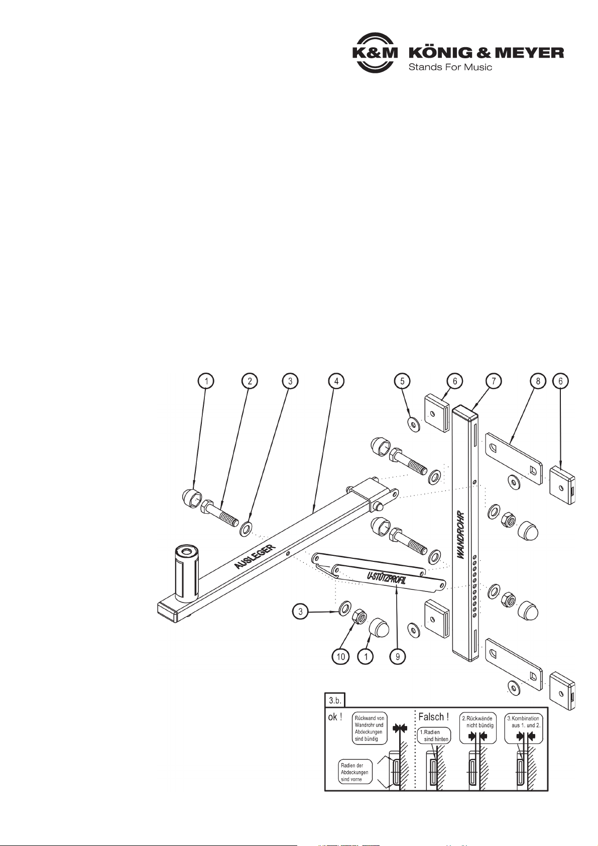
a. Jeweils eine Abdeckung 6 auf die Laschen 8 bis zum Einrasten aufschieben
b. Laschen durch Schlitze des Wandrohres 7 schieben.
b. BEACHTE: Teile dabei so halten, dass Rückwand von Rohr und Abdeckung
b. eine Linie bilden UND die Rundung der Abdeckung nach vorne zeigt (s.Abb.3.b.)
c. Nun die restlichen beiden Abdeckungen 6 bis zum Einrasten aufschieben
d. U-Stützprofil 9 mit (oben offener) U-Lasche an Wandrohr 7 schrauben:
d. - Schraubensatz 1-2-3-3-10-1
d. BEACHTE: bei Benutzung der obersten Bohrung des Wandrohres 7 steht
d. der Ausleger 4 in waagerechter Position (siehe Kapitel 8 ABMESSUNG)
e. Ausleger 4 mit (unten offener) U-Lasche an Wandrohr 7 schrauben:
e. - Schraubensatz 1-2-3-3-10-1
f. U-Stützprofil 9 mit Ausleger 4 verbinden:
f. - Schraubensatz 1-2-3-3-10-1
g. Die vier U-Scheiben, groß 5 dienen als Unterlage zur Wandbefestigung
2. TEILE – ÜBERSICHT
Sichtprüfung vornehmen,
ob Teile vollständig und
in Ordnung sind.
4 Ausleger
7 Wandrohr
9 U-Stützprofil
im Beutel:
1 8 x Kappen SW10
2 3 x Schrauben M6 x 60 mm
3 6 x U-Scheiben, klein (ø6,4 mm)
5 4 x U-Scheiben, groß (ø8,4 mm)
6 4 x Laschenabdeckung
8 2 x Befestigungslasche
10 3 x Sicherungsmuttern M6
Vielen Dank, dass Sie sich für dieses Produkt entschieden haben. Diese Anleitung informiert Sie über alle wichtigen Schritte bei Aufbau
und Handhabung. Wir empfehlen, sie auch für den späteren Gebrauch aufzubewahren.
24110 Boxenwandhalterung
- für Lautsprecher bis zu max. 50 kg
- Gleichermaßen geeignet für: Heim-, Objekt-, Öffentlicher Bereich
- mit patentiertem Spreizdorn für wackelfreien Lautsprechersitz
- passend für Flanschbuchsen-Innendurchmesser 35-37 mm
- Ausleger neigbar von 0° bis 22° (in 10 Stufen)
- Richtung des Lautsprechers beliebig fixierbar durch Spreizdorn
Page 2
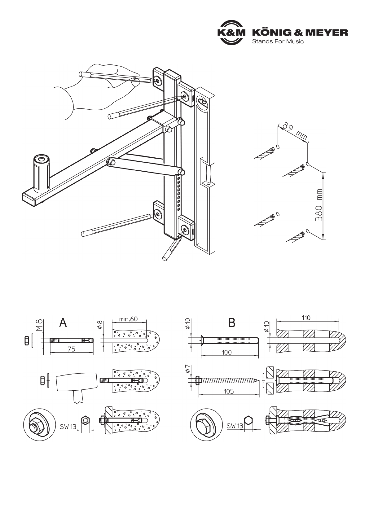
5. BEFESTIGUNGSBEISPIELE
A. Betonwand: Bsp.: Bolzen-Anker M8 x 75 mm
A. - aufbohren, Loch ausblasen, Anker einschlagen, Befestigungslaschen anbringen, U-Scheibe setzen, Mutter mit 20 Nm anziehen.
B. Lochsteine: Bsp.: Kunststoff-Rahmendübel ø 10 x 100 mm mit Holzschraube DIN571 ø 7 x 105 mm
B. - aufbohren, Loch ausblasen, Dübel setzen, Befestigungslaschen anbringen, U-Scheiben setzen, Schrauben eindrehen.
C. sowohl für Beton als auch für Lochsteine geeignet: Einspritzmörtel-Verankerungen
C. - ohne Siebhülse für Vollmauerwerk und Beton.
C. - mit Siebhülse für Lochsteine.
C. Vorteil: Befestigung arbeitet spreizdruckfrei, dadurch kann die Halterung beliebig oft ausgewechselt werden und erlaubt eine
C. randnahe Befestigung (nicht unter 100 mm Abstand).
C. Genaue Montagehinweise entnehmen Sie bitte den Beipackinformationen der Produkte.
4. WANDMONTAGE
- Halterung senkrecht ausrichten
- und Bohrlöcher markieren
- Dübellöcher bohren 4x
- (ø 8 bei Bolzen-Anker; ø 10 bei Rahmendübel)
Page 3
6. MONTAGE DES LAUTSPRECHERS
SICHERHEITSHINWEISE
- ausreichend Personal einsetzen bei Montage, Demontage und Neigungsverstellung des Lautsprechers (am besten 2 fachlich und
- körperlich geeignete Personen).
- auf funktionstüchtiges Lautsprechermaterial achten, d.h. die Aufsteckbuchse muss über die richtige Größe und Güte verfügen.
- angemessenes Installationsgerät verwenden: z.B. sichere Leitern o.ä.
- erst ordnungsgemäßen Zustand der Halterung prüfen (z.B. richtig installiertes Stützrohr 9), dann Lautsprecher aufbringen.
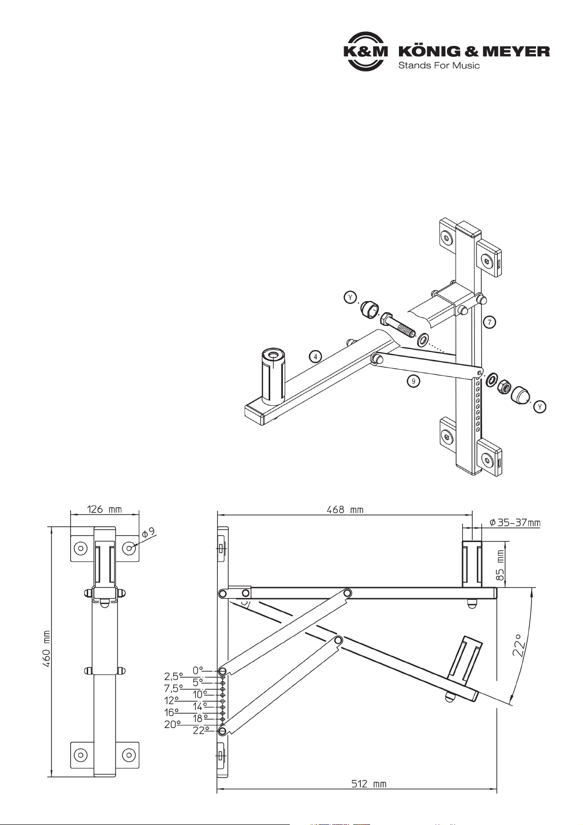
7. AUSLEGER NEIGEN
- ACHTUNG: vor Verstellung der Neigung ggf. erst den Lautsprecher abnehmen
- ACHTUNG: oder durch zweite Person während des ganzen Verstellvorgangs
- ACHTUNG: zuverlässig und sicher halten.
- Verschraubung Y zwischen Wand- und Stützrohr lösen und Teile aus der Bohrung ziehen.
- Stützrohr an gewünschter Stelle wieder mit Wandrohr verschrauben.
- Der Ausleger kann in elf Neigungswinkeln (siehe Kapitel 8. ABMESSUNGEN) positioniert werden.
8. ABMESSUNGEN
Page 4

9. LAUTSPRECHER AUFBRINGEN
11. PRÜFEN, INSTANDHALTEN, REINIGEN
- Beim Einsatz der Halterung in "Veranstaltungs- und Produktionsstätten für szenische Darstellung" gelten die BGV C1.
- Bei Wartungsarbeiten auf Gefährdungen achten (Einklemmen, Anstoßen, herunterfallende Gegenstände etc.) und entsprechend sichern.
- Zur Reinigung am besten ein leicht feuchtes Tuch und ein nicht scheuerndes Reinigungsmittel benutzen.
FEHLERSUCHE (F) und BESEITIGUNG (B)
F: Bauteile der Halterung wackeln: B: Schraubverbindungen festziehen.
F: Lautsprecher taumelt auf Steckbolzen: B: Mutter unterhalb des Steckbolzen festziehen/Buchse größer 37 mm.
F: Lautsprecher läßt sich nicht verdrehen: B: siehe Kapitel 10.: LAUTSPRECHER VERDREHEN
a. Box mit Flanschbuchse auf Steckbolzen des Tragarmes setzen.
a. - Lautsprecher in die gewünschte Richtung drehen.
b. Schutzkappe 1 abnehmen.
c. Mutter 2 mit Schlüssel fest anziehen; das presst die Backen des Steckbolzens an die Innenwand der Lautsprecherbuchse.
c. ACHTUNG: eine so platzierte Box von Hand zu verdrehen ist nicht mehr möglich und stellt einen MISSBRAUCH dar.
c. - Schutzkappe wieder auf Mutter stecken.
10. LAUTSPRECHER VERDREHEN bzw. ABNEHMEN
d. - Schutzkappe abnehmen
d. - Mutter lösen, aber nicht vollständig herausdrehen
e. Um die verkeilten Backen des Steckbolzen vom Lautsprecher zu lösen ist ein Schlag mit einem Gummihammer erforderlich.
e. Dieser ist -mit Gefühl- von unten in axialer Richtung auf den Gewindebolzen zu führen, so daß sich die Backen lösen.
f. Der Lautsprecher kann nun wieder verdreht bzw. vom Steckbolzen abgenommen werden.
KÖNIG & MEYER GmbH & Co. KG
Kiesweg 2, 97877 Wertheim, www.k-m.de
24110-000-55 Rev.13 03.80.335.00 5/17
TECHNISCHE DATEN / SPEZIFIKATIONEN
Material
Rohre und Laschen - Stahl, schwarz gepulvert
Schrauben, Muttern - Stahl, verzinkt
Abdeckungen, Backen - PA, PE
Traglast max. 50 kg
Abmessungen H x B x T: 460 x 126 x 512 mm, Steckbolzen: ø 35-37 x 85 mm
Karton H x B x T: 85 x 145 x 540 mm
Eigengewicht 2,7 kg / 2,9 kg mit Karton
Zubehör Adapterhülse 21326: für Lautsprecherbuchsen mit ø 38 mm (=US-Variante)
Page 5

3. ASSEMBLY
1. SAFETY NOTES
- please check the support arms prior to and after use. Please do not use damaged support arms
- do not exceed the max. centric load of 50 kg
- not suitable for outdoors or moist rooms.
- please refer to local mounting instructions/regulations (may possibly deviate from the examples provided in Sections 5 A,B,C)
- use 4 screws for the wall mount
- only use trained technicians to assemble/mount the system
- only mount on suitable walls with the corresponding assembly material (not included in the delivery)
- walls that are too weak or have electrical and water conduits are not suitable. In case of doubt, consult a qualified technician.
- check that the screws are tight and the condition of the system regularly.
- careful and attentive handling is required when adjusting the system - due to the possibility of pinching or wedging your hand.
- when using the mount at "events and production sites for scenic presentations" BGV C1 applies accordingly.
a. Pace each cover 6 on the bracket 8 until it clicks into place.
b. Place bracket through the slit in the wall tube 7
b. ATTENTION: Hold the pieces in such a way that the back of the tube and the cover
b. form a line AND the round part of the cover faces forward (see. Illustration 3.b.)
c. Now place the other two covers 6 until they click into place.
d. Screw the U-support profile 9 with (top open) a U bracket to the wall tube 7:
d. - Screw set 1-2-3-3-10-1
d. ENSURE: when using the top bore hole in the wall tube 7 that the
d. extension arm 4 is in a horizontal position (see chapter 8 DIMENSIONS).
e. Screw the extension arm 4 with (bottom open) a U bracket into the wall tube 7:
e. - Screw set 1-2-3-3-10-1
f. connect the U-support profile 9 with the extension arm 4:
f. - Screw set 1-2-3-3-10-1
g. The four U discs, large 5 are used a washers for the wall mount
2. PARTS - OVERVIEW
Conduct a visual inspection to
ensure that all the parts are
included and are in working
order.
4 extension arm
7 wall tube
9 U-support profile
in the bag:
1 8 x caps
2 3 x screws M6 x 60 mm
3 6 x U-discs, small (ø6.4 mm)
5 4 x U-discs, large (ø8.4 mm)
6 4 x bracket covers
8 2 x bracket
10 3 x securing nuts M6
Thank you for choosing this product. The instructions provide directions to all of the important setup and handling steps. We
recommend you keep these instructions for future reference.
24110 Speaker Wall Mount
- for loudspeakers up to max. 50 kg
- equally suited for home, object and public venues
- with a patented expanding mandrel ensuring wobble-free loudspeaker hold
- suitable for flange bushings - internal diameter 33-37 mm
- Extension arm range from 0° to 22° (in 10 positions)
- loudspeaker can face any direction using the expanding mandrel
Page 6

5. MOUNT EXAMPLES
A. Concrete wall. Example: Bolt anchor M8 x 75 mm
A. - drill, clean hole, hammer in the anchor, mount the bracket. Set the U disk, tighten the nut with 20 Nm.
B. Perforated brick: Example: Plastic frame anchors ø 10 x 100 mm with wood screw DIN571 ø 7 x 105 mm
B. - drill, clean hole, set the anchor, mount the bracket. Set the U disc, tighten the screws.
C. Suitable for both concrete and perforated brick: Injection molded anchor
C. - without sieve bushing for concrete wall.
C. - with sieve bushing for perforated bricks.
C. Advantage: mount without expansion; as such the mount can be used as often as needed and ensures mounting right up to the
C. edge (not under 100 mm distance).
C. Please follow the assembly/mounting instructions provided with the products.
4. WALL MOUNT
- Place the mount in a vertical position and mark
- the bore holes
- Drill the anchor holes 4x
- (ø 8 for the bolt anchor; ø 10 for frame anchor)
Page 7

6. USAGE NOTES / FUNCTION
SAFETY NOTES
- ensure that there are enough technicians available for the assemble/mounting and disassembly/dismounting and setting of the
- position/angle of the loudspeakers (we recommend 2 technicians that are physically fit)
- ensure that the loudspeaker material is in working order, e.g. the connector must be the right size and quality.
- ensure that suitable installation equipment and tools are used: e.g. safe ladders among others.
- first check that the mount is in proper working order (e.g. properly install support tube 9, then mount the loudspeakers.
7. POSITION THE EXTENSION ARM ANGLE
- ATTENTION: prior to positioning the extension arm, first remove the loudspeaker,
- ATTENTION: or have a second person hold the loudspeaker securely
- ATTENTION: while positioning the angle.
- Unscrew the screw Y between the wall and the support tube and remove the parts from the bore hole.
- Place the support tube in the desired position and screw it to the wall tube.
- The extension arm can be positioned in 11 positions (refer to Section 8 DIMENSIONS).
8. DIMENSIONS
Page 8

9. MOUNT THE LOUDSPEAKER
11. CHECK, MAINTENANCE, CLEANING
- When using the mount at "events and production sites for scenic presentations" BGV C1 applies accordingly.
- In the event of system maintenance pay attention to possible risks (wedging/pinching, it is hit or bumped into, falling objects) and ensure
- against such risks, accordingly.
- To care for the product use a damp cloth and a non-abrasive cleaning agent.
FAULT FINDING (F) and SOLUTION (S)
F: Mounting parts are not stable: S: Tighten the screws.
F: Loudspeaker sways back and forth on the locking pin: S: Tighten the nut beneath the locking pin / bushing greater than 37 mm.
F: Loudspeaker cannot be positioned: S: see Section 10: POSITION LOUDSPEAKER
a. Place the speaker with the flange adapter on the locking bolt/pin of the support arm.
a. - set the speaker in the desired direction.
b. remove the protective cap 1.
c. Tighten the 2 nut, this presses the end of the locking plates to the internal wall of the loudspeaker connector.
c. ATTENTION: such placement may not be done by hand and would represent IMPROPER USE.
c. - Place the protective cap on the nut.
10. REPOSITION OR REMOVE THE LOUDSPEAKER
d. - Remove the protective cap
d. - loosen the nut, but do not remove it completely
e. To release the wedge locking plates from the loudspeaker it is necessary to hit the bolt with a rubber mallet to loosen the wedge lock.
e. This is to be done by carefully hitting from the bottom - in the axial direction towards the threaded bolt, so that the wedge locking plates loosen.
f. The loudspeaker can be repositioned or removed from the locking pin.
KÖNIG & MEYER GmbH & Co. KG
Kiesweg 2, 97877 Wertheim, www.k-m.de
24110-000-55 Rev.13 03.80.335.00 5/17
TECHNICAL DATA / SPECIFICATIONS
Material
tubes and brackets - steel, black powder coating
screws, nuts - steel, galvanized
cover, locking plates - PA, PE
Load max. 50 kg
Dimensions H x W x D: 460 x 126 x 512 mm, socket pins: ø 35-37 x 85 mm
Karton H x W x D: 85 x 145 x 540 mm
Weight net 2.7 kg / gross: 2.9 kg
Accessories adapter sleeve 21326: for loudspeaker bushing with 38 mm internal diameter (= US variation)
 Loading...