

Page 1
KÖNIG & MEYER GmbH & Co. KG
Kiesweg 2, 97877 Wertheim, www.k-m.de
22150-300/500-55 Rev.05 / 22160-300/500-55 Rev.06/08 03-79-103-00 7/20
22150/22160 Deckenstativ
Hängende Mikrofon-Haltevorrichtung - stufenlos höhenverstellbar
Einmal an der Decke befestigt - beliebige und schnelle Montage und Demontage
Hervorragende geeignet für Studio und Übungsraum
STECKBRIEF
Vielen Dank, dass Sie sich für dieses Produkt entschieden haben. Diese Anlei tung informiert Sie über alle wich tigen Schritte bei Aufbau und Handhabung.
Wir empfehlen, sie auch für den späteren Gebrauch aufzubewahren.
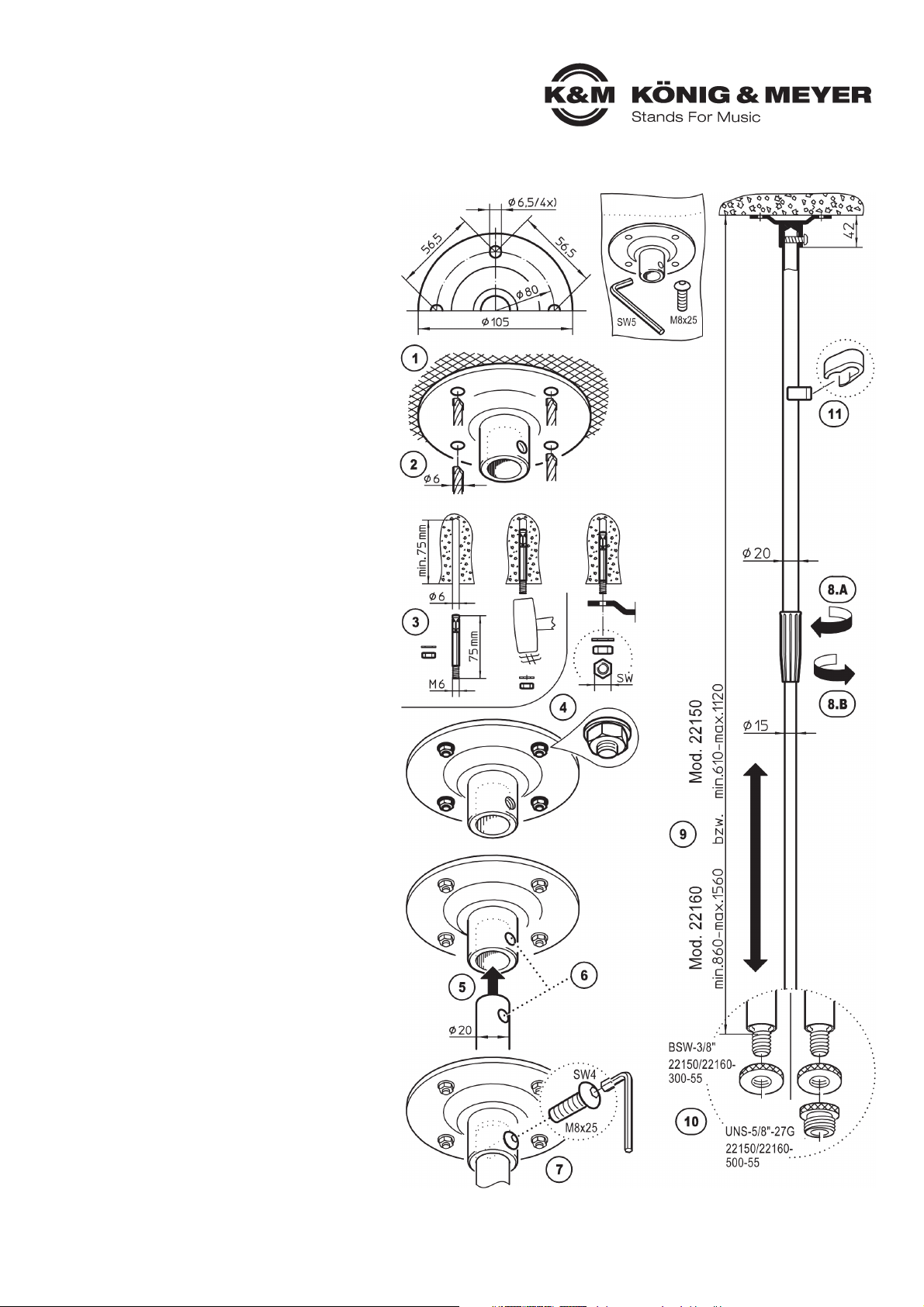
Modell: 22150-300-55 = 3/8"-Gewinde (610-1120 mm)
Modell: 22150-500-55 = inklusive 5/8"-Reduziergewinde
Modell: 22160-300-55 = 3/8"-Gewinde (860-1560 mm)
Modell: 22160-500-55 = inklusive 5/8"-Reduziergewinde
Deckenflansch: Stahlplatte ø 105 x 4 mm mit 4 Bohrungen ø 6,5/80 mm;
Deckenflansch: mit Stutzen zur Aufnahme des Grundrohres ø 20 mm
STATIV 22150: Grundrohr ø 20 x 550 mm, Auszug ø 15 x 550 mm,
STATIV 22150: Höhe ist stufenlos einstellbar: 610 – 1120 mm
STATIV 22160: Grundrohr ø 20 x 800 mm, Auszug ø 15 x 750 mm,
STATIV 22160: Höhe ist stufenlos einstellbar: 860 – 1560 mm
STATIV 22160: schnelle Verstellung mittels griffiger Spannmuffe;
STATIV 22160: Gewinde (3/8"; 5/8") für Mikrofon oder Schwenkarm
Material: Platte, Stutzen, Rohre: Stahl, gepulvert
Material: Gewinde: Stahl, verzinkt
Material: Spannmuffe, Hülse, Bremse, Kabelhalter: PA
Oberflächen: pulverbeschichtet, schwarz
Daten: Traglast: max. 1 kg, ausschließlich für Mikrofone,
Daten: Karton: 1010 x 100 x 50 mm, 0,3 kg
Daten: Gewicht 22150: net.1,1 kg - 22160: net.1.35 kg
Besonderheiten: Die Rohrkombination darf nur in vertikaler Lage
Besonderheiten: montiert werden - andernfalls nimmt das Stativ Schaden
SICHERHEITSHINWEISE
Die Betriebssicherheit des Stativs hängt maßgeblich ab von:
a. TRAGLAST: ausschließlich Mikrofone bis 1 kg
b. HANDHABUNG: korrekte Montage und Bedienung
c. DECKE: muss eben und tragfähig sein
d. ÄUSSERE UMSTÄNDE: vor Seitenkräften wie
d. Wind, Stößen, Publikum?, etc. schützen
- Zunächst Sichtprüfung vornehmen ob alle Bestandteile vollständig
- und soweit erkennbar in Ordnung sind
- Beschädigte Teile dürfen nicht bzw. nicht mehr eingesetzt werden
- Nicht für Außen- bzw. Feuchträume
- Beachten Sie die örtlich gültigen Befestigungsanweisungen
- (evtl. abweichend von den Beispielen in Kapitel 2,3.)
- Benutzen Sie 4 Schrauben/Anker für die Deckenbefestigung
- Montage durch ausgebildetes Installationspersonal
- Montage nur an geeigneter Decke mit entsprechendem
- Montagematerial (nicht im Lieferumfang)
- Ungeeignet sind Decken die zu schwach sind oder hinter
- denen Strom- und Wasserleitungen oder dgl. verlegt sind.
- Im Zweifel einen qualifizierten Fachmann zu Rate ziehen.
- Prüfen Sie regelmäßig die Festigkeit der Installation.
- Gewinde fest aber nicht überfest anziehen (Handkraft genügt);
- Diese regelmäßig auf Festsitz kontrollieren und ggf. nachziehen.
- Reinigen mit leicht feuchtem Tuch und nicht scheuernden
- Reinigungsmitteln
AUFSTELLUNG & FUNKTIONEN
A. DECKENFLANSCH
1. Geeignete Decke sowie Befestigungsmaterial wählen
1. BEISPIEL-Betondecke: z.B. Bolzen-Anker M6 x 75 mm
1. Platte ausrichten, Bohrlöcher markieren
2. Vier Löcher bohren (ø 6 mm) und ausblasen
3. Bolzen-Anker einschlagen, Flansch anbringen
4. U-Scheiben platzieren und Muttern festziehen
B. ROHRKOMBINATION
5. Grundrohr in Stutzen schieben
6. Bohrungen von Grundrohr und Stutzen abgleichen
7. Linsenkopfschraube bis zum Anschlag eindrehen
HÖHE
8.A - Auszugrohr festhalten während der Spanngriff gelöst wird
9.
A - Auszugrohr in gewünschte Höhe schieben
8.B - Spanngriff wieder anziehen (fest, nicht überfest)
C. MIKROFONIERUNG
10 - Die Mikrofonanschlussgewinde sind je nach Modell ausgeführt
10 - in 3/8" oder 5/8" und verfügen über eine Rändelscheibe
11 - Die Deckenstative verfügen über eine Kabelklemme, welche
11 - über das Grundrohr geclipst und dort verschoben werden kann.
BEMERKUNGEN ZUM EINSATZ VON SCHWENKARMEN
Die Deckenstative 22150 und 22160 sind nicht mit Schwenkarmen
ausgestattet. Der Einsatz eines solchen ist natürlich möglich.
Wir empfehlen jedoch, dessen Auslage möglichst kurz zu halten, um
die Biegebeanspruchung welche dadurch auf die senkrechte Rohrkombination wirkt, gering zu halten.
Zubehörbeutel
Page 2

KÖNIG & MEYER GmbH & Co. KG
Kiesweg 2, 97877 Wertheim, www.k-m.de
Rev.02 03-80-900-00 7/20
3. Sicherungsmaßnahmen
2. Allgemeine Montagehinweise
ALLGEMEINE SICHERHEITSUND MONTAGEHINWEISE
MONTAGEZUBEHÖR für Lasten über Personen (z. B. Wand-, Decken- und Truss-Halterungen)
1. Allgemeine Sicherheitshinweise
Dieses Montagezubehör darf ausschließlich montiert und verwendet werden:
- von sachkundigem, mit den einschlägigen Vorschriften vertrautem Fachpersonal,
- gemäß den örtlichen und staatlichen Vorschriften sowie den berufsgenossenschaftlichen Vorschriften
- wie in der Montageanleitung (=Aufstell- und Bedienungsanleitung) beschrieben,
- nach erfolgter fehlerfreier Funktions- u. Sichtprüfung (Vollständigkeit, Betriebssicherheit; insbesondere ist zu achten auf: Verformungen, Kerben, Risse,
- Verschleiß, Schäden an Gewinden; Korrosion und Lesbarkeit von Kennzeichnungen),
- ohne Änderung oder Bearbeitung der Komponenten,
- im Innenbereich (nicht in Feuchträumen).
- Montage von sachkundigem Personal durchführen lassen.
- Je nach Beschaffenheit der Wände/Decken sowie der Belastungsart sind Befestigungsmittel in geeigneter Bauart und ausreichender Dimensionierung
- zu verwenden.
- Berücksichtigen Sie insbesondere die verminderte Tragfähigkeit von Wand- und Deckenverkleidungen sowie von Vorsatz- und Dämmverschalungen.
- Für alle Verschraubungen sind die angegebenen Anzugsmomente unbedingt einzuhalten. Falls nichts angegeben ist gelten die maximalen
- Anzugsmomente für die jeweilige Verschraubung.
Boxensysteme sind im Bereich von Bühnen oder Studios gegen Herabfallen zu sichern. Zweierlei wird unterschieden:
1. Ortsveränderliche Montage (z.B. geflogene Lautsprecher, Montage mittels C-Haken an Traversen, von Hand lösbare Befestigungselemente)
1. erfordert am Gerät ein zweites, unabhängig wirkendes Sicherungselement.
2. Ortsfeste Montage ermöglicht es, auf das zweite Sicherungselement zu verzichten, wenn die Befestigung ausreichend bemessen,
2. nur mit Werkzeug zu lösen sowie gegen Selbstlockern gesichert ist.
2. Wir empfehlen Ihnen trotzdem ein zweites Sicherungselement zu verwenden.
4. Sicherheitsfaktoren
Befestigungsmittel von Lautsprecherboxen sind sicherheitsrelevante Teile, welche im Falle eines Versagens Leben und Gesundheit von Menschen
gefährden können. Je nach Verwendungsland des Artikels sind die länderspezifischen Normen und Richtlinien für den Bereich „Lautsprecher“
einzuhalten bzw. zu beachten.
5. Prüfung und Wartung
Das Halten von Lasten über Publikum ist höchst sicherheitsrelevant und erfordert ein entsprechendes Bewusstsein der möglichen Gefährdung. Die
sicherheitstechnische Überprüfung des Montagezubehörs ist unumgänglich. Werden an Zubehörteilen Schäden und/oder Fehlfunktionen festgestellt,
darf das Produkt erst nach vollständiger Instandsetzung wieder benutzt werden.
- Zunächst ist vor jeder Inbetriebnahme eine Sicht- und Funktionsprüfung durchzuführen, wobei insbesondere auf Verformungen, Risse, Verschleiß,
- Korrosion, fehlerfreie Funktion und die Lesbarkeit von Kennzeichnungen zu achten ist.
- Empfohlen und zudem in vielen Staaten vorgeschrieben ist eine regelmäßige Überprüfung von Befestigungs- und Zubehörteilen. Wir empfehlen eine
- jährliche Sichtprüfung durch sachkundiges Fachpersonal sowie zusätzlich eine eingehende Prüfung durch einen amtlichen Sachverständigen im
- Abstand von vier Jahren.
- Dringend empfehlen wir das Führen eines Prüfbuches. In diesem werden alle Zubehörteile mit ihren Daten der wiederkehrenden Prüfung eingetragen
- wo sie jederzeit für evtl. Kontrollen einzusehen sind.
Page 3

KÖNIG & MEYER GmbH & Co. KG
Kiesweg 2, 97877 Wertheim, www.k-m.de
22150-300/500-55 Rev.05 / 22160-300/500-55 Rev.06/08 03-79-103-00 7/20
Model: 22150-300-55 = 3/8"-thread (610-1120 mm)
Model: 22150-500-55 = including 5/8"- thread adapter
Model: 22160-300-55 = 3/8"-thread (860-1560 mm)
Model: 22160-500-55 = including 5/8"- thread adapter
Ceiling flange: Steel plate ø 105 x 4 mm with 4 drill holes ø 6.5/80 mm;
Ceiling flange: with base tube supports ø 20 mm
STAND 22150: Base tube ø 20 x 550 mm, Extension tube ø 15 x 550 mm,
STAND 22150: Variable height adjustment: 610 – 1120 mm
STAND 22160: Base tube ø 20 x 800 mm, Extension tube ø 15 x 750 mm,
STAND 22160: Variable height adjustment: 860 – 1560 mm
STAND 22160: quick adjustment through the non-slip clutch;
STAND 22160: Thread (3/8"; 5/8") for the microphone or boom arm
Material: Plate, support, tube: Steel, powder coating
Material: Threads: Steel, galvanized
Material: Clutch, sleeve, brake, cable holder: PA
Surfaces: powder coated, black
Data: Weight bearing load: max 1 kg, exclusively for microphones,
Data: Box 1010 x 100 x 50 mm, 0.3 kg
Data: Weight 22150: net. 1.1 kg - 22160: net. 1.35 kg
Particulars: The tube combination may only be mounted
Particulars: vertically, otherwise damage to the stand is possible
Operational safety is largely dependent on:
a. LOAD BEARING WEIGHT: exclusively microphones up to 1 kg
b. HANDLING correct mounting and use
c. Ceiling: must be load bearing and even.
d. EXTERNAL CIRCUMSTANCES: protect against lateral
d. forces such as wind, being bumped into and the public etc...
- First, conduct a visual inspection to ensure that all the parts are included
- and to the extent possible are in working order.
- Damaged parts may not i.e. may no longer be used
- Not suitable for outdoors or moist rooms
- Please refer to local mounting instructions
- (May possibly deviate from the examples provided in Section 2.3)
- Use 4 screws/anchors for the ceiling mount
- Only use trained technicians to install the system
- Only mount on suitable ceilings with the corresponding
- assembly material (not included in the delivery)
- Ceilings, that are too weak or have electrical and water conduits are not
- suitable. In case of doubt, consult a qualified technician.
- Check the stability of the installation regularly.
- Tighten the threads, but do not over-tighten (manual tightening is
- sufficient) Check that the connection is tight on a routine basis,
- tighten if needed.
- To care for the product, use a damp cloth and a non-abrasive
- cleaning agent.
A. CEILING FLANGE
1. Select suitable ceiling and mounting materials
1. EXAMPLE- Concrete ceiling: e.g. Bolt-Anchor M6 x 75 mm
1. Position plate, mark the drill holes.
2. Drill four holes (ø 6 mm) and blow out the holes
3. Hammer in the bolt anchor, place the flange
4. Place the U disks and tighten the nuts
B. TUBE COMBINATION
5. Place the base tube in the support
6. Adjust the drill holes and supports
7. Screw in the raised head screw as far as it will go
HEIGHT
8.A - Hold the extension tube while the tension handle is loosened
9.
A - Adjust the extension tube to the desired height
8.B - Tighten the tension handle (tight, not too tight)
C. ATTACH MICROPHONE
10 - The microphone connector threads are either 3/8" or 5/8” depending
10 - on the model and come with a knurled washer
11 - The Ceiling mounts come with a cable clamp, which
11 - can be clipped to the base tube or placed anywhere on the tube
COMMENTS REGARDING THE USE OF BOOM ARMS
Ceiling mounts 22150 and 22160 are not equipped with boom arms.
The use of a swivel arm is an option. We recommend, however, that it
not be extended too far, to keep the pull to a minimum on the extended
arm and the vertical tube combination.
Accessory bag
22150/22160 Ceiling mount
Hanging microphone holding system - variable height adjustment
Once attached to the ceiling it can be quickly attached and taken down any time
Perfect for studios and rehearsal rooms
PROFILE
Thank you for choosing this product. The instructions provide information to all
of the important setup and handling steps. We recommend you keep these
instructions for future reference.
SAFETY NOTES
SETUP & FUNCTIONS
Page 4

These mounting accessories may only be mounted and used:
- by qualified personnel familiar with the relevant regulations,
- in accordance with local and state regulations and the regulations for occupational insurance schemes
- as described in the assembly instructions (=installation and operating instructions),
- after a fault-free functional and visual inspection (completeness, operational safety; special attention must be paid to deformations, notches, cracks,
- wear, damage to threads; corrosion and legibility of markings),
- without changing or processing the components,
- indoors (not in damp rooms).
- The installation should be carried out by qualified personnel.
- Depending on the nature of the walls/ceilings and the type of load, fasteners of suitable design and sufficient dimensions must be used.
- In particular take into account the reduced load-bearing capacity of wall and ceiling coverings, facing plywood and insulation panelling.
- The specified tightening torques must be observed for all screw connections. If nothing is specified, the maximum tightening torques for the respective
- screw connection apply.
Box systems must be secured against falling down in the area of stages or studios. A distinction is made between two types of protection:
1. Mobile installation (e.g. flying speakers, installation using C-hooks on trusses, manually detachable fastening elements) requires a second,
1. independently acting safety element on the unit.
2. Stationary mounting allows the second securing element to be dispensed with if the fastening is sufficiently dimensioned and can only be detached
2. with tools plus being protected against self-loosening.
2. Nevertheless, we recommend using a second securing element.
KÖNIG & MEYER GmbH & Co. KG
Kiesweg 2, 97877 Wertheim, www.k-m.de
Rev.02 03-80-900-00 7/20
3. Safety measures
2. General installation instructions
GENERAL SAFETY AND
ASSEMBLY INSTRUCTIONS
MOUNTING ACCESSORIES for overhead installations (e.g. wall, ceiling and truss mounts)
1. General safety instructions
4. Safety factors
Fasteners of loudspeaker boxes are safety-relevant parts that can endanger life and health of people in case of failure. Depending on the country in
which the article is used, the country-specific standards and guidelines for the sector "loudspeakers" must be observed respectively followed.
5. Inspection and maintenance
Overhead mounting is highly security relevant and requires an appropriate awareness of the potential danger. A safety inspection of the mounting
accessories is essential. If damage and/or malfunctions are found on accessories, the product must not be used again until it has been completely
overhauled.
- First of all, a visual and functional check must be carried out before initial operation, paying particular attention to deformations, cracks, wear,
- corrosion, fault-free functioning and the legibility of markings.
- A regular inspection of fastening and accessory parts is recommended and also mandatory in many countries. We recommend an annual visual
- inspection by qualified personnel and additionally a detailed inspection by an official expert every four years.
- We urgently recommend keeping an inspection logbook for the recurring tests where all accessories are entered together with their data and where
- they can be viewed at any time for possible inspections.
 Loading...