

Page 1
18863 Laptopablage für »Spider Pro«
BESTIMMUNGSGEMÄSSER GEBRAUCH
Formschöner Laptopaufsatz passend zum
18860 »Spider Pro« und 18840 »Baby Spider Pro«
MERKMALE & FÄHIGKEITEN
- Stabil und trotzdem leicht dank einer Materialkombination aus Stahl und Aluminium
- Die Auflageplatte...
- ...verfügt über verstellbare Anschläge die sich allen gängigen Laptopmodellen,
- ...Mixern, CD-Playern, etc. anpassen lassen
- ...kann mit minimalem Aufwand in 4 Positionen geneigt werden: 0° - 15° - 25° - 35°
- ...bietet Platz für 4 geräteschonende Auflage-Pads die individuell aufgeklebt werden
- ...misst in der Breite 304 mm und in der Tiefe 265 mm (Nutzfläche: 270 x 230 mm)
SICHERHEITSHINWEISE
Vielen Dank, dass Sie sich für dieses Produkt entschieden haben. Bitte lesen und beachten Sie vor Aufbau
und Betrieb dieses Produkts sorgfältig diese Anleitung. Sie informiert Sie über alle wichtigen Schritte, um eine
sichere Handhabung zu gewährleisten. Wir empfehlen, sie auch für den späteren Gebrauch aufzubewahren.
- Max. zentrische Belastung: 8 kg
- Nur für den Innenbereich, nicht in Feuchträumen
- Die Möglichkeit das Produkt zu verstellen birgt
- naturgemäß Einklemmgefahren: umsichtige Hand-
- habung ist daher unverzichtbar
- Produkt einer Sichtprüfung unterziehen: beschädigte
- Teile dürfen zunächst nicht eingesetzt werden bzw.
- erst nach qualifizierter Instandsetzung
- Für die ordnungsgemäße Befestigung der Laptopablage
- folgen Sie bitte den Schritten dieser Anleitung. Dazu
- zählt Insbesondere die korrekte Vorbereitung des
- Deckels des »Spider Pro« (Art. 18840, 18860)
- Platzieren Sie die Traglast (Laptops, sonstige Geräte)
- stets zentrisch sowie an den vorderen Anschlägen
- Prüfen Sie regelmäßig die Festigkeit der Installation,
- insbesondere der Schraubverbindungen
- Traglast von der Laptophalterung abnehmen bei:
- - Änderung der Neigung (4 Stellungen) sowie bei
- - Ortswechsel oder Wartungsarbeiten beim »Spider Pro«
- Sicherheitshinweise des »Spider Pro« beachten
AUFSTELLANLEITUNG
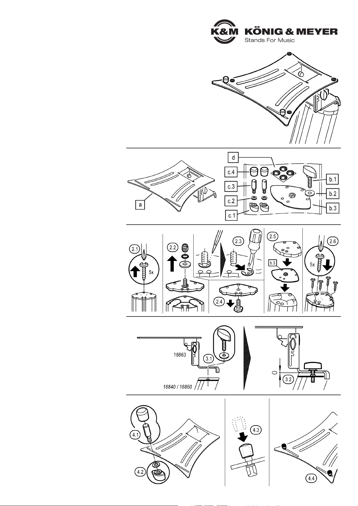
1. BESTANDTEILE
Bitte Sichtprüfung vornehmen, ob alle Teile vollständig
vorhanden und soweit erkennbar in Ordnung sind.
a.1 Laptopablage (vormontiert)
b.1 Klemmschraube M8 x 33 mm
b.2 U-Scheibe ø 8,4/24 mm
b.3 Befestigungsplatte (am »Spider Pro«)
c.1 Anschläge, je 2x:
c.1 Flügelmutter 21 mm/M5
c.2 U-Scheibe ø 5,3/10 mm
c.3 Anschlagbolzen ø 8/M5
c.4 Gummikappe ø 15 mm
d
.4 Gummiauflagen (4x, selbstklebend), ø 13 mm
2. VORBEREITUNG des »Spider Pro«
Damit der »Spider Pro« die Laptopablage 18863
aufnehmen kann, muss der Deckel des Stativs umgebaut
werden - falls nicht schon geschehen.
2.1 Alle 5 Schrauben des Deckels komplett entfernen
2.2 Ggf. Reduziergewinde, Gummiring und U-Scheibe
2.2 vom Gewindebolzen des Deckels entfernen
2.3 Schraubenzieher (o.ä.) am Seegering ansetzen und
2.3 diesen vom Gewindebolzen wegziehen
2.4 Gewindebolzen nun vom Deckel entfernen
2.5 Zunächst die Befestigungsplatte b.3 auf die
2.5 Stativsäule legen und darüber auch den Deckel
2.6 Abschließend wieder alle 5 Schrauben eindrehen.
3. MONTAGE des 18863 am »Spider Pro«
3.1 Haltewinkel der Laptopablage auf dem Deckel des
3.1 »Spider Pro« anlegen und per Klemmschraube M8 b.1
3.1 und zwischenliegender U-Scheibe b.2...
3.2 ...fest miteinander verschrauben (Handkraft genügt).
Die Demontage erfolgt in umgekehrter Reihenfolge.
4. ANSCHLAGBOLZEN MONTIEREN
4.1 Anschlagbolzen c.3 von oben durch einen der beiden
4.1 unteren Schlitze der Auflageplatte schieben. Die
4.1 seitlichen Abflachungen des Bolzens dienen als
4.1 Verdrehschutz und müssen in den Schlitz eintauchen.
4.2 Flügelmutter c.1 und U-Scheibe c.2 von unten mit
4.2 dem Gewinde des Anschlagbolzens verschrauben
4.3 Gummikappe c.4 auf den Anschlagbolzen pressen
4.4 Zweiten Anschlag in gleicher Weise montieren.
1. BESTANDTEILE
2. VORBEREITUNG des »Spider Pro«
3. MONTAGE des 18863 am »Spider Pro«
4. ANSCHLAGBOLZEN MONTIEREN
Page 2
KÖNIG & MEYER GmbH & Co. KG
Kiesweg 2, 97877 Wertheim, www.k-m.de
18863-000-56 Rev.03 03-79-712-00 2/20
TECHNISCHE DATEN
Material
Haltewinkel und Lasche:
Stahl, pulverbeschichtet, schwarz
Auflageplatte:
Aluminium, pulverbeschichtet, schwarz
Schrauben, Scheiben: Stahl, verzinkt
Kappen, Griffe, Noppen: PE, PA, PUR, schwarz
Traglast max. 8 kg zentrische Last
Maße
Auflageplatte: B x T: 304 x 265 mm
Packmaß: 304 x 265 x 120 mm
Karton innen: 382 x 260 x 142 mm
Gewicht 1,4 kg
WARTUNG, PFLEGE
- Schonender Umgang erhält die Funktion und die
- Langlebigkeit
- Periodische Betätigung beweglicher Teile erhält deren
- Gängigkeit
- Pflege und Wartung sind stets im unbelasteten Zustand
- durchzuführen
- Bei Wartungsarbeiten bestehen evtl. aufgrund von:
- -Kanten, -gelösten Verbindungen, -beweglichen Teilen
- - Gefährdungen durch Quetschen und Stoßen; zur
- - Vermeidung ist mit gebotener Vorsicht und ggf.
- - Handschuhen zu arbeiten
- Beschädigte Teile dürfen nicht weiterverwendet werden,
- d.h. sie müssen ersetzt bzw. repariert werden
- Prüfen Sie regelmäßig den:
- a. Festsitz der Schraubverbindung (3.2) zwischen der
- a. Laptopablage 18863 und dem »Spider Pro«
- b. ordnungsgemäßen Zustand der Bauteile der
- b. Laptopablage:
- b. -Gestell, -Anschläge, -Schraubverbindungen,
- b. -Gummiauflagen
- Schmutz, Feuchtigkeit und ggf. Korrosion sind zu entfernen
- Zur Pflege ein leicht feuchtes Tuch und ein nicht
- scheuerndes Reinigungsmittel benutzen
BENUTZERHINWEISE
FUNKTIONEN
FEHLERSUCHE (F) und BESEITIGUNG (B)
F: Installation wackelt
F: B: Ist die Halterung spielfrei mit dem »Spider Pro« verschraubt
F: B: Sitzen die seitlichen Bolzen in den Schlitzen am Anschlag 5.4.
F: B: Gelockerte Schraubverbindungen anziehen
F: Traglast sitzt nicht richtig bzw. wackelt
F: B: Position der Anschlagbolzen 7 prüfen und berichtigen
F: B: Vollzähligkeit und richtige Position der Gummiauflagen d auf der Aufnahmeplatte prüfen und ggf. herstellen
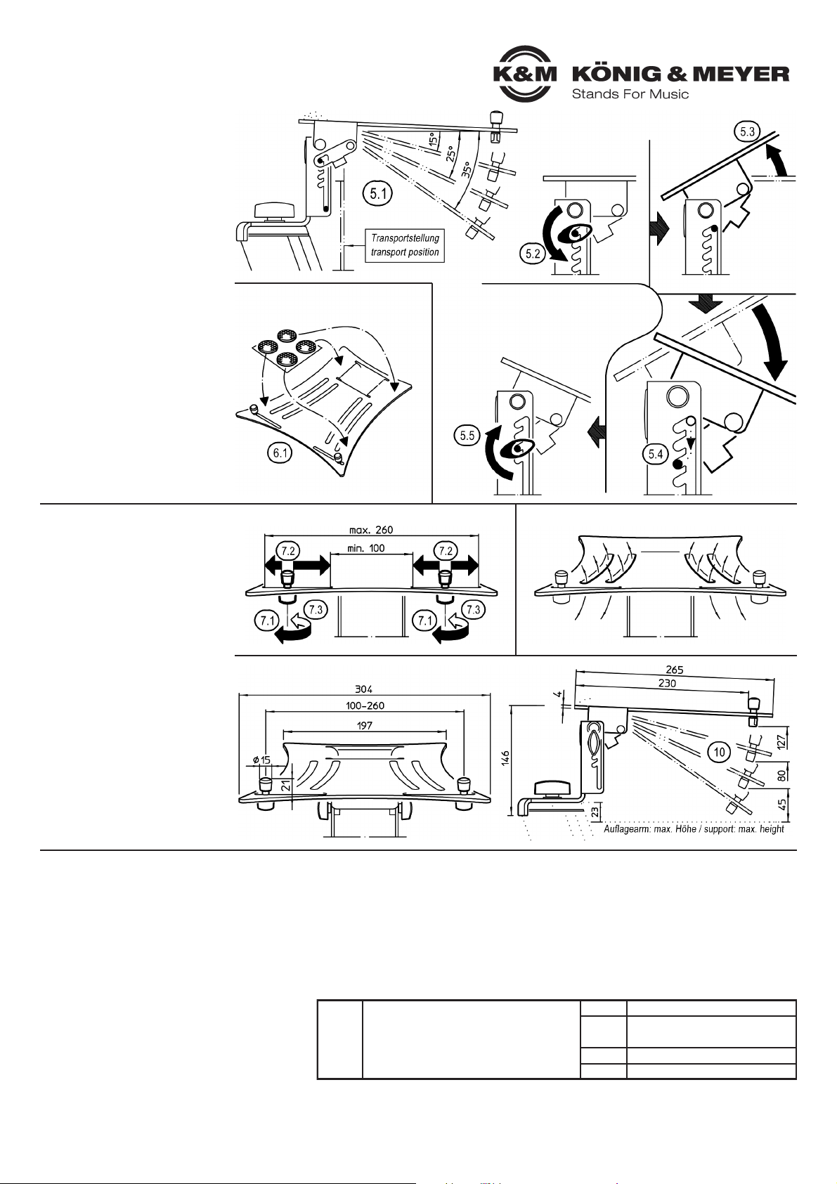
5. NEIGUNGSWINKEL EINSTELLEN
5.1 Einstellbare Neigungswinkel:
5.1 ~ 0° (waagerecht)
5.1 - 15°
5.1 - 25°
5.1 - 35°
5.1 - 90° (zusammengeklappt
5.1 - 90° = Transportstellung)
5.2 Beide Klemmen lockern
5.3 Auflageplatte anheben bis sich die
5.3 seitlichen Bolzen im senkrechten
5.3 Schlitz befinden
5.4 Diese Bolzen nun in die gewünschten
5.4 schrägen Schlitze führen - bis zum
5.4 Anschlag
5.5 Beide Klemmen wieder festziehen
6. GUMMIAUFLAGEN PLATZIEREN
6.1 Die vier Gummiauflagen werden auf
6.1 die Auflageplatte geklebt, wobei die
6.1 genauen Abstände abhängen von
6.1 den Dimensionen der Traglast
6.1 (Laptop etc.).
7. ANSCHLÄGE ANPASSEN
7.1 Flügelmuttern c.1 lockern…
7.2 …und Anschlagbolzen nach
7.2 Wunsch seitlich verschieben
7.3 Flügelmuttern wieder fest anziehen
8. LÜFTUNGSSCHLITZE
Die vier geschwungenen Schlitze in
der Auflageplatte dienen der besseren
Belüftung des abgestellten Gerätes.
9. ABMESSUNGEN
10. NEIGUNG VERSTELLEN
Siehe Vorgehensweise in Kapitel 5.
5. NEIGUNGSWINKEL EINSTELLEN
6. GUMMIAUFLAGEN PLATZIEREN
7. ANSCHLÄGE ANPASSEN
9. ABMESSUNGEN
8. LÜFTUNGSSCHLITZE
Page 3

18863 Laptop rest for the »Spider Pro«
PROPER USE
Beautifully shaped laptop attachment suitable for
18860 »Spider Pro« and 18840 »Baby Spider Pro«
FEATURES & ABILITIES
- Sturdy yet lightweight thanks to a material combination of steel and aluminium
- The support plate...
- ...has adjustable stops that fit all common laptop models, mixers, CD players, etc.
- ...can be tilted in 4 positions with minimum effort: 0° - 15° - 25° - 35°
- ...offers space for 4 device-gentle support pads which are individually glued on
- ...measures 304 mm in width and 265 mm in depth (effective area: 270 x 230 mm)
SAFETY INSTRUCTIONS
Thank you for choosing this product. Please read and follow these instructions carefully before installation
and use. They inform you about all important steps regarding assembly and handling. We recommend that
you keep them for future reference.
- Max. centric load: 8 kg
- For indoor use only, not in damp rooms
- The possibility of adjusting the product naturally involves
- the risk of trapping: careful handling is therefore essential
- Subject the product to a visual inspection: damaged parts
- must not be used initially or only after qualified repair
- For proper attachment of the laptop shelf, please follow
- the steps in this manual. This includes in particular the
- correct preparation of the lid of the »Spider Pro«
- (Art. 18840, 18860)
- Always place the load (laptops, other devices) centrally
- and at the front stops
- Regularly check the strength of the installation,
- especially the screw connections
- Remove the load from the laptop holder:
- - Changing the inclination (4 positions) and
- - Change of location or maintenance work on the
- »Spider Pro«
- Observe safety instructions of the »Spider Pro«
INSTALLATION INSTRUCTIONS
1. COMPONENTS
Please carry out a visual inspection to ensure that all parts
are complete and, as far as recognisable, in good order.
a.1 Laptop shelf (pre-assembled)
b.1 Clamping screw M8 x 33 mm
b.2 Washer ø 8,4/24 mm
b.3 Mounting Plate (on »Spider Pro«)
c.1 Stops, 2x each:
c.1 Wing nut 21 mm/M5
c.2 Washer ø 5,3/10 mm
c.3 Stop bolt ø 8/M5
c.4 Rubber cap ø 15 mm
d
.4 Rubber pads (4x, self-adhesive), ø 13 mm
2. PREPARATION of the »Spider Pro«
In order for the »Spider Pro« to be able to accommodate
the laptop shelf 18863, the lid of the tripod must be
converted - if not already done.
2.1 Remove all 5 screws of the lid completely
2.2 If necessary, remove the reduction thread, rubber ring
2.2 and washer from the threaded bolt of the cover
2.3 Place a screwdriver (or similar) on the circlip and
2.3 pull it away from the threaded bolt
2.4 Now remove the threaded bolt from the cover
2.5 First place the mounting plate b.3 on the stand
2.5 column and then place the cover
2.6 Finally, screw in all 5 screws again.
3. MOUNTING the 18863 on the »Spider Pro«
3.1 Place the retaining bracket of the laptop shelf on the
3.1 lid of the »Spider Pro« and screw it tightly together
3.1 with the clamping screw M8 b.1 and the washer b.2...
3.2 ...(manual force is sufficient).
Dismantling is carried out in reverse order.
4. MOUNTING THE STOP BOLTS
4.1 Push the stop bolt c.3 from above through one of the
4.1 two lower slots of the support plate. The lateral
4.1 flattenings of the bolt serve as an anti-rotation
4.1 protection and must enter the slot.
4.2 Screw wing nut c.1 and washer c.2 from below with
4.2 the thread of the stop bolt
4.3 Press rubber cap c.4 onto the stop bolt
4.4 Mount the second stop in the same way.
1. COMPONENTS
2. PREPARATION of the »Spider Pro«
3. MOUNTING the 18863 on the »Spider Pro«
4. MOUNTING THE STOP BOLTS
Page 4

KÖNIG & MEYER GmbH & Co. KG
Kiesweg 2, 97877 Wertheim, www.k-m.de
18863-000-56 Rev.03 03-79-712-00 2/20
TECHNICAL DATA
Material
Mounting bracket and bracket:
Steel, powder-coated, black
Support plate:
Aluminium, powder-coated, black
Screws, washers: Steel, galvanized
Caps, handles, knobs: PE, PA, PUR, black
Load max. 8 kg centric load
Dimensions
Support plate: W x D: 304 x 265 mm
Pack size: 304 x 265 x 120 mm
Carton inside: 382 x 260 x 142 mm
Weight 1.4 kg
MAINTENANCE, CARE
- Gentle handling preserves the function and longevity
- Periodic actuation of moving parts preserves their
- movement
- Maintenance and servicing must always be carried out
- in unloaded condition
- Maintenance work may be necessary due to:
- - During maintenance work there may be danger of
- - crushing and impact due to: edges, loosened connections,
- - moving parts; to avoid this, work must be carried out with
- - due care and, if necessary, gloves
- Damaged parts must not be reused, i.e. they must be
- replaced or repaired
- Regularly check the:
- a. tightness of the screw connection 3.2 between
- a. the Laptop Tray 18863 and the »Spider Pro«
- b. proper condition of the components of the Laptop Tray:
- b. -frame, -stops, -screw connections, -rubber supports
- Dirt, moisture and any corrosion must be removed
- Use a slightly damp cloth and a non-abrasive cleaning
- agent for maintenance
USER INSTRUCTIONS
FUNCTIONS
FAULT-FINDING (F) and REPAIR (R)
F: Installation wobbles
F: R: Is the support bolted to the »Spider Pro« without play
F: R: Are the lateral bolts in the slots seated against the stop 5.4.
F: R: Tighten loosened screw connections
F: Load is not seated correctly or wobbles
F: R: Check and correct the position of the stop bolts 7
F: R: Check that the rubber supports (d) on the mounting plate are complete and in the correct position and,
F: R: if necessary, rectify herstellen
5. ADJUSTING THE ANGLE OF INCLINE
5.1 Adjustable angles of inclination:
5.1 ~ 0° (horizontal)
5.1 - 15°
5.1 - 25°
5.1 - 35°
5.1 - 90° (folded up
5.1 - 90° = transport position)
5.2 Loosen both clamps
5.3 Lift the support plate until
5.3 the lateral bolts are in
5.3 the vertical slot
5.4 Now guide these bolts into the desired
5.4 diagonal slots - until the stop
5.5 Retighten both clamps
6. PLACING RUBBER PADS
6.1 The four rubber pads are glued to
6.1 the support plate, the exact distances
6.1 depending on the dimensions of
6.1 the load (laptop etc.).
7. ADAPT THE STOPS
7.1 Loosen wing nuts c.1…
7.2 …and move the stop bolt
7.2 sideways as desired
7.3 Tighten wing nuts again
8. VENTILATION SLOTS
The four curved slots in the support
plate serve for better ventilation of
the parked unit.
9. DIMENSIONS
10. ADJUST INCLINATION
See procedure in chapter 5.
5. ADJUSTING THE ANGLE OF INCLINE
6. PLACING RUBBER PADS
7. ADAPT THE STOPS
9. DIMENSIONS
8. VENTILATION SLOTS
 Loading...