

Page 1
18820 Keyboard-Tisch »Omega Pro«
- schlanke und doch hochfeste Stahlrohrkonstruktion
- unkomplizierte und fein abgestufte Höhenverstellung
- individuell positionierbare Auflagearme - je nach Breite des Keyboards
- klappbare Beine für ein flaches Packstück - ideal für den mobilen Einsatz
- passendes Design zu den Keyboardbänken 14080, 14085 und 14086
- optional erhältliche Aufsätzen 18811 (2.Ebene) und 18822 (3.Ebene)
- viele weitere Anbaumöglichkeiten (siehe Kapitel: TECHNISCHE DATEN)
- max. Traglast: 80 kg, inklusive Anbauten
- Standfläche B x T 975 x 575 mm, Höhe 600-1020 mm,
- Auflagen B x T max. 790 x 345 mm
SICHERHEITSHINWEISE
1. BESTANDTEILE
2. MONTAGE
Vielen Dank, dass Sie sich für dieses Produkt entschieden haben. Diese Anleitung
informiert Sie über alle wichtigen Schritte bei Aufbau und Handhabung. Wir empfehlen,
sie auch für den späteren Gebrauch aufzubewahren.
ALLGEMEIN
- Die Möglichkeit, das Produkt zu verstellen, birgt naturgemäß Einklemmgefahren.
- Umsichtige und aufmerksame Handhabung bei Aufbau, Betrieb, Abbau und
- Wartung sind daher unverzichtbar.
- Das Stativ vor widrigen äußeren Einflüssen schützen (Nässe, Wind, Stöße)
- Die pflegliche und sorgsame Behandlung erhält die Funktionstüchtigkeit,
- Langlebigkeit und dient nicht zuletzt der Sicherheit
- Ein beschädigtes Produkt darf zunächst nicht weiter eingesetzt werden;
- beschädigte Teile müssen vor Gebrauch ersetzt oder instandgesetzt werden
BETRIEB
- Maximale Traglast 80 kg (inklusive Anbauten)
- Auf tragfähige und ebene Untergründe achten
- Die Rastbolzen beider Klemmschrauben müssen stets eingerastet sein
- Bei Verstellung der Höhe sind die Keyboards zuvor stets zu entfernen
- Die maximale Höhe ist erreicht sobald am Fußrohr die STOP-Markierung
- sichtbar wird (siehe Kapitel HÖHENVERSTELLUNG)
- beide Fußrohre müssen immer auf die gleiche Höhe eingestellt werden
- die lange Seite der Auflagen muss in die Richtung der langen Fußseite zeigen
- Schraubverbindungen müssen fest angezogen sein
AUFBAUANLEITUNG
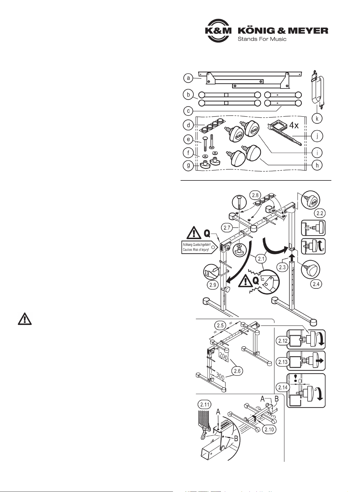
1. BESTANDTEILE
a U-Bügel, klappbar, b Fußrohre kpl. (2x), c Auflagenarme kpl. (2x), k Tragegurt
Zubehörbeutel:
d Gummiauflagen ø 20 x 5 mm (4x), e Schloßschraube M6 x 65 mm (2x), f U-Scheibe ø 6,4 mm (2x),
g Flügelmutter M6 (2x), h Klemmschraube mit Logo (2x), i Klemmschraube ohne Logo (2x)
j Klettband / Kabelbinder (4x)
2. MONTAGE
STATIV (2.1-2.4)
2.1 Beide Standrohre des U-Bügels a bis Zum Anschlag aufklappen.
WARNUNG! Bei diesem Vorgang entsteht eine Quetschgefahr im Bereich Q.
Halten Sie deshalb unbedingt ihre Gliedmaßen, Kleidung und andere Dinge
aus diesem Bereich fern. Das gilt ebenso für Dritte.
2.2 Klemmschrauben i in die Gewindebuchsen der oberen Ecken einschrauben und
2.2 darauf achten, dass die Rastbolzen in die Bohrung der Standrohre eintauchen.
2.3 Fußrohre b in die Standrohre schieben und durch...
2.4 ...Eindrehen der Klemmschrauben h deren (gleiche) Höhe fixieren.
AUFLAGENARME (2.5-2.7) (siehe auch Kapitel 6 – EINSTELLUNGEN)
2.5 Wir empfehlen die symmetrische Anbringung der beiden Auflagenarme.
2.6 Die lange Seite der Auflage muss in Richtung des langen Fußrohres zeigen.
2.7 Schloßschrauben e durch die Auflage c und gewünschte Bohrung des
2.7 U-Bügels stecken und mit U-Scheibe f und Flügelmutter g verschrauben.
ACCESSORIES (2.8-2.11)
2.8 GUMMIAUFLAGEN d sind selbstklebend und können bei Bedarf an gewünschter
Stelle der Auflagen c platziert werden - z.B. dann, wenn das Instrument ein zu geringe
Tiefe aufweist um die beiden großen Gummischoner abzudecken.
2.9 KLETTBÄNDER j sorgen für Ordnung bei der Verkabelung. Diese können an beliebiger
Stelle positioniert werden. Einfach einfädeln, zusammenziehen und zusammendrücken.
Die Klettbänder können ebenso einfach wieder gelöst werden. Das Verschieben der
Bänder entlang des Rohres ist ebenso möglich.
2.10 Klettbänder dienen auch der Sicherung der zusammengeklappten Fußrohre.
2.11 Der TRAGEGURT k ist eine willkommene Hilfe beim Transport des Keyboardtisches.
Vorgang: - Keyboardtisch auf den Auflagerohren c abstellen
Vorgang: - Füße zusammenklappen
Vorgang: - beide Karabinerhaken in die Bohrungen (A oder B) einhängen
KLAPPFUNKTION & TRANSPORT (2.12-2.14)
Keyboardtisch umdrehen und auf den Auflagerohren c abstellen
2.12 Angezogene Klemmschraube i ca. eine Umdrehung lösen
2.13 Deren Griff ziehen (= Bolzen entriegeln) und halten, Fuß nun einklappen.
2.14 ERNEUTES AUFKLAPPEN: zuerst TRAGEGURT 2.11 une KLETTBAND 2.10 entfernen;
anschließend Griff i ziehen und halten, Fuß aufklappen (90°), Klemmschraube i eindrehen
2.10
Das Aufklappen der Füße
beim Transport wird verhindert durch das straffe
Anziehen von mind. einem
Klettband um beide Füße.
2.14
BEACHTE:
Das Gewinde der Klemmschraube i darf nicht ins
Innere des Rohres ragen,
Der Fuß kann dann nicht
vollständig aufgeklappt
werden. In diesem Falle
wird die Klemmschraube
so weit wie nötig zurückgedreht.
Page 2
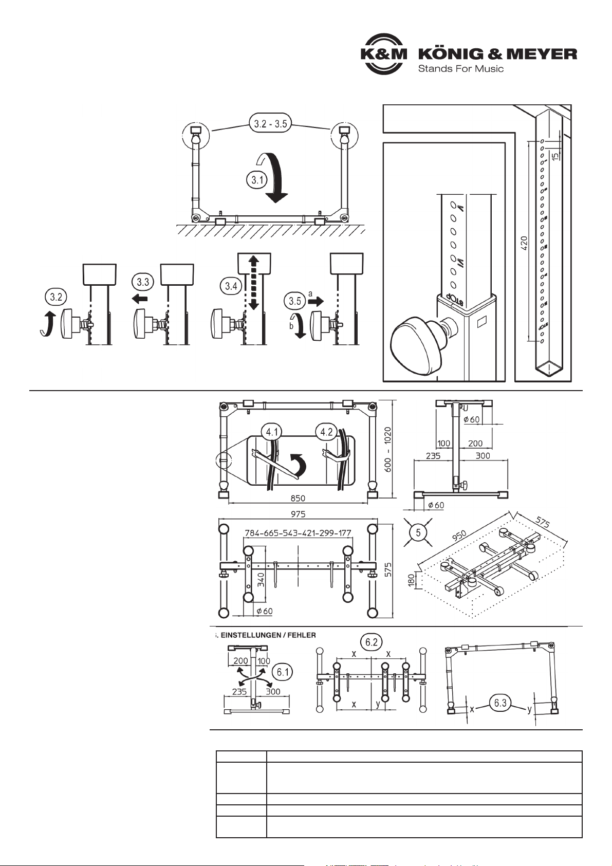
6. EINSTELLUNGEN / FEHLER
BENUTZERHINWEISE / FUNKTIONEN
4. FIXIERUNG VON KABELN
Die Montage der Kabelbinder (= Klettbänder) ist in
Kapitel 2.9 dargestellt und beschrieben.
4.1 Kabel am Rohr anlegen
4.2 Das lose Ende des Klettbandes um das Kabel
4.2 schlagen und andrücken. Je nachdem wie straff
4.2 das Klettband angezogen wird, ergibt sich ein
4.2 eher lockerer bzw. fester Sitz des Kabels.
5. ABMESSUNGEN
HÖHE: 600 - 1020 mm (in 15 mm-Schritten)
STAND: Breite 975mm, Tiefe 575 mm
AUFLAGE: Breite max. 784 mm, Tiefe 340 mm
TRANSPORT: 950 x 575 x 180 mm
6. EINSTELLUNGEN / FEHLER
Falsche Einstellungen können die Sicherheit der
Installation gefährden und müssen korrigiert werden:
6.1 Der längere Teil der Auflage darf sich nicht
6.1 über dem kurzen Teil des Fußrohres befinden.
6.2 Die beiden Auflagen sollten nicht außermittig (x:y),
6.2 sondern symmetrisch zur Mitte (x:x) platziert werden.
6.3 Beide Fußauszugrohre dürfen keinesfalls auf un-
6.3 gleiche Höhen eingestellt werden (siehe Kapitel 3).
Klemmschraube h
etwas losdrehen
3. HÖHENEINSTELLUNG
3. des FUSSROHRES
Empfohlene Vorgehensweise
nacheinander für beide Fußrohre:
3.1 Keyboardtisch umdrehen und
3.1 auf den Auflagen abstellen
3.2 Klemmschraube h etwas losdrehen
3.3 Griff der Klemmschraube ziehen
3.4 Fußrohr ein- bzw. ausfahren
3.5 Bolzen einrasten lassen und
3.5 Klemmschraube festdrehen
HINWEIS:
Beide Fußrohre müssen aus Gründen
der Sicherheit stets auf die gleiche
Höhe eingestellt werden.
PRÜFEN / INSTANDHALTEN
- bei Wartungsarbeiten bestehen ggf. aufgrund von:
- -Kanten, -gelösten Gewinden, -beweglichen Teilen etc.
- Gefährdungen durch Quetschen und Stoßen;
- um dies zu vermeiden ist mit gebotener Vorsicht und
- ggf. Schutzausrüstung (z.B. Handschuhen) zu arbeiten
- zur Reinigung am besten ein leicht feuchtes Tuch und
- ein nicht scheuerndes Reinigungsmittel benutzen
FEHLERSUCHE (F) & BESEITIGUNG (B)
F: Die Füße lassen sich nicht vollständig aufklappen
F: B: Klemmschraube zurückdrehen bis das Gewinde
F: B: nicht mehr ins Rohrinnere ragt (2.14)
F: Keyboardtisch steht wackelig
F: B: Schraubverbindungen und Untergrund prüfen
F: Keyboardtisch steht schief
F: B: Fußrohre auf gleiche Höhe einstellen (siehe 6.3)
F: Instrument befindet sich außer der Mitte
F: B: ggf. Position der Auflagen korrigieren (6.1 und 6.2)
Griff ziehen bis der
Sicherungsbolzen
sich nicht mehr
im Eingriff befindet
Griff gezogen halten
und das Fußrohr
ein- bzw. ausfahren
Sicherungsbolzen in
gewünschtes Loch rasten
lassen und Klemmschraube
wieder fest anziehen
Der Tisch kann in der Höhe in 29 Stufen
zu je 15 mm Abstand eingestellt werden.
Jedes vierte Absteckloch der Fußrohre ist mit einer römischen Ziffer
markiert; das erleichtert es sehr,
beide Fußrohreauf die erforderliche
gleiche Höhe einzustellen.
Die STOP
Markierung
zeigt den
maximalen
Auszug an.
TECHNISCHE DATEN / SPEZIFIKATIONEN
Farbvarianten 18820-019-55 schwarz, -76 reinweiß, -91 rubinrot
Material
Rohre, Winkel: Stahl, gepulvert
Schrauben, Scheiben: verzinkt
Kunststoffteile: PA, PE, PC, TPE
Verpackung Einzelkarton: 960 x 620 x 59 mm
Gewicht 9,8 kg
Zubehör
(optional)
18811 Aufsatz-1, 18822 Aufsatz-2, 18814 Adapter, 18805 Notenhalter, 18817 Universalhalter,
18815 Laptophalter, 18806 Rollschlitten, 18829 Tasche,197... Tablethalter, 211... Schwenkarme
KÖNIG & MEYER GmbH & Co. KG
Kiesweg 2, 97877 Wertheim, www.k-m.de
18820-019-55/76/91 Rev.04 03-80-384-00 4/19
Page 3

18820 Table-style keyboard stand
»Omega Pro«
- a slim yet high-strength tubular steel construction
- uncomplicated, graduated height adjustment
- individually positionable support arms – according to width of keyboard
- foldable legs for flat packaging - ideal for mobile use
- design matches keyboard benches 14080, 14085 and 14086
- optional attachments 18811 (2nd level) and 18822 (3rd level) are available
- for more mounting options see chapter: TECHNICAL DATA
- max. load: 80 kg including additions
- base w x d 975 x 575 mm, height 600-1020 mm,
- supports w x d max. 790 x 345 mm
SAFETY INSTRUCTIONS
1. COMPONENTS
2. ASSEMBLY
Thank you for choosing this product. This instruction manual informs you about the
important steps to set up and handle the product. We recommend to keep the manual
in a separate place for a possible later use.
GENERAL
- The possibility to adjust the product involves entrapment hazards. Therefore careful
- and thoughtful handling during installation, operation, dismantling and maintenance
- is essential.
- Protect the stand from adverse external conditions (moisture, wind, shocks).
- The careful and diligent treatment preserves the functionality,
- durability and ensures last not least safety.
- Faulty products are not to be used; damaged parts must be replaced or repaired
- before handling
OPERATION
- Maximum load 80 kg (including additions)
- Ensure that the subsurfaces are stable and even
- The locking bolt of both clamping screws must always be engaged
- Always remove the keyboards before you adjust the height
- The maximum height is reached as soon as the STOP mark on the stand tube
- becomes visible (see chapter HEIGHT ADJUSTMENT)
- both tubes must always be adjusted to the same height
- The long side of the supports must point in the direction of the long base sides
- Screw connections must be firmly tightened
SET-UP INSTRUCTIONS
1. COMPONENTS
a U-bracket, foldable, b base tubes complete (2x), c support arms complete (2x), k carrying strap
Accessories bag:
d rubber pads ø 20 x 5 mm (4x), e carriage bolt M6 x 65 mm (2x), f washer ø 6,4 mm (2x),
g wing nut M6 (2x), h clamping screw with logo (2x), i clamping screw without logo (2x)
j Velcro / cable tie (4x)
2. ASSEMBLY
STAND (2.1-2.4)
2.1 Unfold both stand tubes of the u-bracket a all the way to the stop.
WARNING! During this procedure there is entrapment hazard in area Q.
It is therefore essential that you keep your limbs, clothing and other things
out of the area. This also applies to third parties.
2.2 Screw the clamping screws i into the threaded bushings of the upper corners and
2.2 make sure that the locking bolts are immersed in the boreholes of the stand tubes.
2.3 Insert the base tubes b into the stand tubes...
2.4 ...and by screwing the clamping screws h fix their (equal) height.
SUPPORT ARMS (2.5-2.7) (see also Chapter 6 - SETTINGS)
2.5 We recommend symmetrical mounting of the two support arms.
2.6 The long side of the support must point in direction of the long base tube.
2.7 Insert carriage bolt e through the support c and the desired borehole of
2.7 the u-bracket and screw together with washer f and wing nut g.
ACCESSORIES (2.8-2.11)
2.8 RUBBER PROTECTIVE LAYERS d are self-adhesive and can when needed
be placed c on the desired position of the support – e.g. if the depth of the
instrument is too small to cover the two large rubber protectors.
2.9 VELCRO STRAPS j keep the wiring tidy. Velcro straps can be placed at random.
Merely thread, tighten and press together.
The straps can be removed easily. It is also possible to shift the straps along the tubes.
2.10 Velcro straps are also used to secure the folded tubes.
2.11 The CARRYING STRAP k is a welcome help when transporting the keyboard table.
Procedure: - place the keyboard table on the support arms c
Procedure: - fold the legs
Procedure: - hook in both Karabiners into the boreholes (A or B)
FOLDING FUNCTION & TRANSPORT (2.12-2.14)
Turn the keyboard table over and place it on the support arms c
2.12 Loosen tightened clamping screw i approx. one turn
2.13 Pull handle (= unlock bolt) and hold, now retract base.
2.14 RECURRING UNFOLDING: first remove the CARRYING STRAP 2.11 and the VELTRO STRIP 2.10;
afterwards pull and hold handle (i), swing open the legs (90°), tighten clamping screw i.
2.10
The unfolding of the legs
during transport is prevented by securing them with
at least one Velcro strip
around both legs.
2.14
NOTE:
The thread of the
clamping screw (i) must
not protrude in the inside
of the pipe, otherwise the
foot does not fully unfold.
In this case turn back the
clamping screw as far as
necessary.
Page 4

6. SETTINGS / ERRORS
USER INSTRUCTIONS / FUNCTIONS
4. FIXING CABLES
The mounting of the cable ties (= Velcro tapes) is
pictured and described in Section 2.9.
4.1 Fix the cable along the tube
4.2 Wrap the loose end of the Velcro around the cable
4.2 and press. Depending on how close the Velcro is
4.2 fitted, the result will be a loose respectively a tight
4.2 fit of the cables.
5. DIMENSIONS
HEIGHT: 600 - 1020 mm (in 15 mm increments)
STAND: width 975mm, depth 575 mm
SUPPORT: width max. 784 mm, depth 340 mm
TRANSPORT: 950 x 575 x 180 mm
6. SETTINGS / ERRORS
Incorrect settings may compromise the security of
the installation and must be corrected:
6.1 The longer part of the support arms must not be
6.1 placed across the short part of the base tubes.
6.2 The two supports should not be placed off-centre
6.2 (x:y), but symmetrically to the middle (x:x).
6.3 Both stand tubes must always have equal heights
6.3 (see chapter 3).
Unscrew clamping
screw h slightly
3. HEIGHT ADJUSTMENT
3. of the BASE TUBES
Recommended procedure is to adjust
one tube after the other by :
3.1 Turning the keyboard table over and
3.1 placing it on the supports
3.2 Loosen clamping screw h slightly
3.3 Pull handle of the clamping screw
3.4 Extend respectively retract base tube
3.5 Engage the bolts and
3.5 tighten the clamping screw
NOTE:
For reasons of security both base tubes
must always have the same height.
CHECK, MAINTAIN
- Incorrect settings during maintenance can cause
- health hazards arising from: -edges, -loosened threads,
- -movable parts, etc. To avoid this, take due care and
- work where necessary with protective equipment
- (e.g. gloves)
- Clean with a damp cloth. Do not use abrasive
- cleaning agents
FAULT-FINDING (F) and REPAIR (R)
F: The base cannot be fully unfolded
F: R: Unscrew the clamping screw until the thread no
F: R: longer protrudes into the inside of the tube (2.14)
F: Keyboard table wobbles
F: R: Check screw connections and surface
F: Keyboard table stands lopsided
F: R: Adjust base tubes to same height (see 6.3)
F: Instrument is off-centre
F: R: Correct position of support arms if
F: R: necessary (6.1 and 6.2)
Pull handle until the
safety bolts are no
longer engaged
Keep handle pulled
and retract or
extend the tubes
Click safety bolt in the
desired borehole and
retighten clamping screw
The height of the table can be adjusted in
29 steps with a distance of 15 mm each.
Every fourth borehole of the tubes
is marked with a roman numeral;
this making it much easier to adjust
both tubes to the required equal
height.
The STOP
marking
shows the
max.
extraction.
TECHNISCHE DATEN / SPEZIFIKATIONEN
Colour variants 18820-019-55 black, -76 pure white, -91 ruby red
Material
Tubes, angle: steel, powder coated / Screws, washers: galvanized
Plastic parts: PA, PE, PC, TPE
Packaging Single carton: 960 x 620 x 59 mm
Weight 9.8 kg
Accessories
(optional)
18811 Stacker 1, 18822 Stacker 2, 18814 Adapter, 18805 Sheet music and concept holder,
18817 Universal holder, 18815 Laptop holder, 18806 Trolley for Keyboard Stands,
18829 Carrying case,197... Tablet PC holders, 211... Boom arms
KÖNIG & MEYER GmbH & Co. KG
Kiesweg 2, 97877 Wertheim, www.k-m.de
18820-019-55/76/91 Rev.04 03-80-384-00 4/19
 Loading...