

Page 1
18811 Aufsatz für 18810 Keyboard-Tisch »Omega«
- Ideal für ein zweites Keyboard oder ein Laptop
- Tragkraft der oberen Auflage: 25 kg
- Ausbaufähig für dritte Ebene (K&M 18821)
- höhenverstellbar in 10 Stufen
- Auflagenbreite vielfach verstellbar
- 5-fach verstellbar in der Neigung (0°-5°-10°-15°-20°)
- Abmessungen: Höhe: 262-375 mm, Breite: 122-732 mm,
- Tiefe: 400 mm unten, 330 mm oben
SICHERHEITSHINWEISE
- Rast-Klemmschraube 1.c stets fest anziehen
- Auf feste Verschraubung mit dem Stativ achten
- Auflagerohre 1.a sind untereinander immer auf
- gleiche Höhe, Tiefe und Neigung einzustellen
- Auflagegummis 1.f so platzieren, dass das
- Keyboard möglichst sicher und wackelfrei aufliegt.
AUFBAUANLEITUNG
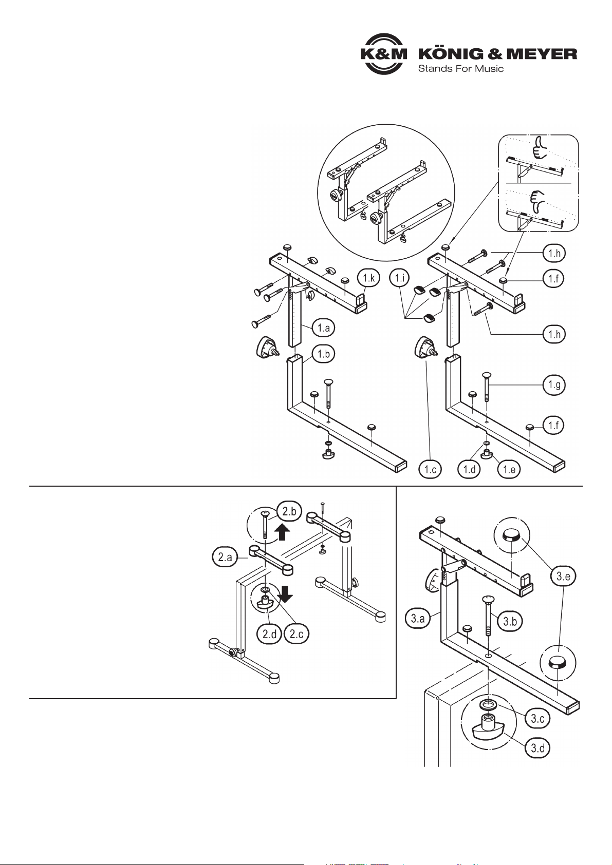
1. BESTANDTEILE
a Auflagerohr (2x)
b L-Grundrohr (2x)
c Rast-Klemmschraube (2x)
d U-Scheibe ø 6,4 mm (2x)
e Klemmmutter M6 (2x)
f Auflagegummi, selbstklebend (8x)
g Schloßschraube M6 x 65 mm (2x)
h Schloßschraube mit Scheibe M5 x 50 mm (6x)
i Klemmmutter M5 (6x)
k Gummischoner (2x)
2. »OMEGA« VORBEREITEN
(siehe auch Kapitel 6.
ABSTAND DER AUFLAGEN)
A ENG stehende Aufsätze
A (z.B. bei Laptop):
A - Auflagerohre 2.a nicht demontieren,
A - da sie das Keyboard tragen.
B WEITER auseinander stehende
B Aufsätze (z.B. bei zweitem Keyboard)
B - Auflagerohre 2.a des Stativs
B - sind evtl. überflüssig und daher
B - besser zu demontieren.
B - Dazu Schloßschrauben 2.b,
B - U-Scheiben 2.c und
B - Klemmmuttern 2.d entfernen.
3. MONTAGE
Aufsatz 18811 am Keyboardtisch befestigen
- gewünschten Abstand der beiden Auflagen festlegen
- L-Grundrohre 3.a mittels Schloßschraube 3.b, U-Scheibe 3.c und Klemmmutter 3.d an
- Querrohr schrauben
- Zweites Aufsatzrohr in gleicher Weise montieren.
- ACHTUNG: beide Aufsätze müssen in gleicher Höhe und Neigung befestigt sein.
- Auflagegummis 3.e an für Keyboard passende Stellen aufkleben.
Vielen Dank, dass Sie sich für dieses Produkt entschieden haben.
Diese Anleitung informiert Sie über alle wichtigen Schritte bei
Aufbau und Handhabung. Wir empfehlen, sie auch für den späteren
Gebrauch aufzubewahren.
KÖNIG & MEYER GmbH & Co. KG
Kiesweg 2, 97877 Wertheim, www.k-m.de
18811-000-55/76/91 Rev.06 03-80-307-00 4/18
Page 2
BENUTZERHINWEISE / FUNKTIONEN
4. HÖHENVERSTELLUNG
VORGEHENSWEISE
FEHLERSUCHE (F) und BESEITIGUNG (B)
F: Aufsatz wackelt B: Rast-Klemmschraube 1.c fest anziehen.
B: Schraubverbindung 3.b, c, d mit dem
B: Keyboardständer ebenfalls fest anziehen.
F: Keyboard wackelt B: Auszüge 1 auf gleiche Höhe bringen bzw.
B: gleiche Neigungswinkel einstellen.
B: Position der Auflagegummis korrigieren 1.f
5. NEIGUNGSWINKEL: 0° - 5° - 10° - 15° - 20°
7. AUFLAGENTIEFE: 4 Positionen
8. ABMESSUNGEN
4.a
Rast-Klemmschraube 1.c
etwas lösen
4.b
Griff ziehen bis
sich der
Sicherungsbolzen
nicht mehr im
Eingriff befindet
A
GERINGER ABSTAND
z.B. für ein Laptop
- Auflagen A.1, A.2 des
- 18810 Omega verbleiben
- wohl am Stativ
B
WEITER ABSTAND
z.B. für ein zweites Keyboard
- Auflagen X des 18810 Omega
- können evtl. entfernt werden
7.a Beide Verschrauben des Auflagerohres komplett lösen
7.b Auflage anders positionieren (4 Möglichkeiten)
7.c BEACHTE: Abstand stets zwei Bohrungen
7.d Beide Verschraubungen wieder montieren
Höhenverstellung:
- 10 Stufen
- Abstand: je 12,5 mm
5.a Verschraubung auseinandernehmen
5.b U-Strebe wie gewünscht ausrichten (5 Varianten)
5.c U-Strebe und Rohr mittels
Schloßschraube abstecken
und mit Klemmmutter
sichern
4.c
Auflagerohr
ein- bzw.
ausfahren
4.d
Sicherungsbolzen in
gewünschtes Loch
einrasten lassen und
Rast-Klemmschraube
wieder fest anziehen
Der Aufsatz kann in der
Höhe in 10 Stufen á
12,5 mm verstellt werden.
6. ABSTAND DER AUFLAGEN
TECHNISCHE DATEN / SPEZIFIKATIONEN
Material
Rohre, Streben: Stahl, pulversbeschichtet schwarz
Schrauben, Scheiben: Stahl verzinkt
Kunststoffteile: PA, TPE, schwarz
Abmessungen
Auflage: Breite: 40 mm
Auflage: Tiefe: unten 400 mm / oben 330 mm
Auflage: Höhe: 262 - 375 mm, Abstand: 122 - 732 mm
Gewicht 4,2 kg
Verpackung L x B x H: 470 x 325 x 90 mm
Zubehör (opt.) 18821 Aufsatz f. 3. Ebene; 18819 Ablage für Controller
PRÜFEN, INSTANDHALTEN, REINIGEN
- bei Wartungsarbeiten auf evtl. Gefährdungen achten
- zur Reinigung ein leicht feuchtes Tuch und ein nicht
- scheuerndes Reinigungsmittel benutzen
(Anschluss an 3.Ebene, K&M 18821)
Auflagerohr
von unten
Page 3

18811 Stacker for 18810 »Omega«
- Ideal for a second keyboard or laptop
- Weight bearing load of the upper stacker: 25 kg
- Expandable for third level (K&M 18821)
- Provides 10 different height adjustment positions
- Stacker width is adjustable
- 5 different angle adjustments (0°-5°-10°-15°-20°)
- Dimensions: Height: 262 - 375 mm, width: 122 - 732 mm,
- depth: 400 mm bottom, 330 mm top
SAFETY NOTES
- Tighten the catch/clamp screw 1.c
- Ensure that it is properly connected to the stand
- Ensure that the support arms 1.a are always set
- to the same height, depth and angle
- Ensure that the rubber rests 1.f are placed such
- that the keyboard is securely in place
SET UP INSTRUCTIONS
1. COMPONENTS
a Support tube (2x)
b L-Base tube (2x)
c Spring-loaded clamping knob (2x)
d Washer ø 6.4 mm (2x)
e Clamping nut M6 (2x)
f Rubber rests, adhesives (8x)
g Carriage bolt M6 x 65 mm (2x)
h Carriage bolt with washer M5 x 30 mm (6x)
i Clamping nut M5 (6x)
k Rubber cover (2x)
2. »OMEGA« PREPARATIONS
(also see Section 6.
STACKER DISTANCE (SUPPORT ARMS))
A Support arms CLOSE TOGETHER
A (e.g. Laptop):
A - Do not disassemble the support tubes 2.a
A - because they support the equipment.
B Support arms FURTHER APART
B (e.g. for second keyboard)
B - Support tubes 2.a may not be
B - needed - it is better to disassemble.
B - Remove the carriage bolts 2.b, U disks
B - 2.c and Clamping nuts 2.d.
3. ASSEMBLY
Attach stacker 18811 to the keyboard table
- Select the desired distance for both support arms
- Screw L-base tube 3.a using a carriage bolt 3.b, U disk 3.c and clamping nut 3.d
- to the vertical tube.
- The second support tube is to be assembled in the same manner.
- NOTE: both support tubes must be set at the same height and angle.
- Adhere the rubber rests 3.e as appropriate.
Thank you for choosing this product. The instructions provide
directions to all of the important setup and handling steps. We
recommend you keep these instructions for future reference.
KÖNIG & MEYER GmbH & Co. KG
Kiesweg 2, 97877 Wertheim, www.k-m.de
18811-000-55/76/91 Rev.06 03-80-307-00 4/18
Page 4

USAGE NOTES / FUNCTIONS
4. HEIGHT ADJUSTMENT
PROCEDURE
FAULT FINDING (F) and REPAIR (R)
F: Stacker wobbles B: Tighten spring-loaded clamping knob 1.c
B: Tighten the keyboard stand’s screw
B: connections 3.b ,c, d
F: The keyboard B: Set the support arms 1 to the same height,
F: wobbles B: same depth and the same angle.
B: Correct the position of the support rubbers.
5. INCLINATION ANGLE: 0° - 5° - 10° - 15° - 20°
7. SUPPORT ARM DEPTH: 4 Positions
8. DIMENSIONS
4.a
Loosen the springloaded clamping
knob 1.c somewhat
4.b
Pull the handle
until the locking
bolt is no longer
in position
A
CLOSE TOGETHER
e.g. for a laptop
- the 18810 Omega
- support arms A.1, A.2
- remain attached to the
- stand
B
FURTHER APART
e.g. for a second keyboard
- The 18810 Omega stacker X
- can be removed if required
7.a Remove both screws from the support tubes
7.b Select a different position (4 possible positions)
7.c NOTE: Distance is always two drill holes
7.d Tighten support tubes again
Height adjustment:
- 10 positions
- Distance: 12.5 mm each
4.c
Adjust the
support
arm up
or down
4.d
Place the lock bolt in
is the desired hole
and let it click into
place then tighten
the spring-loaded
clamping knob
The height of the support
arms can be adjusted in
10 positions, each step is
12.5 mm.
6. STACKER DISTANCE
6. (SUPPORT ARMS)
TECHNICAL DATA
Material
Tubes, struts: Steel, powder coating, black
Screws, discs: Steel galvanized
Plastic parts: PA, TPE, black
Dimensions
Stacker: Width: 40 mm
Auflage: Depth: bottom 400 mm / top 330 mm
Auflage: Height: 262 - 375 mm, Distance: 122 - 732 mm
Weight 4.2 kg
Packaging L x W x H: 470 x 325 x 90 mm
Accessories 18821 Stacker for 3. level; 18819 Controller key. tray
CHECK, MAINTENANCE, CLEANING
- in the event of maintenance pay attention to possible risks
- To care for the product use a damp cloth and a n
- on-abrasive cleaning agent
5.a Disassemble screw connection
5.b Align the U-strut as desired (5 variants)
5.c Place the carriage bolt
through the U-strut and tube
and secure it with a
clamping nut
(Connection to 3. level, K&M 18821)
support tube
from below
 Loading...