

Page 1
24185 Boxenwand-/Deckenhalter
- universell einstellbar durch Kugelgelenk
SICHERHEITSHINWEISE
AUFBAUANLEITUNG
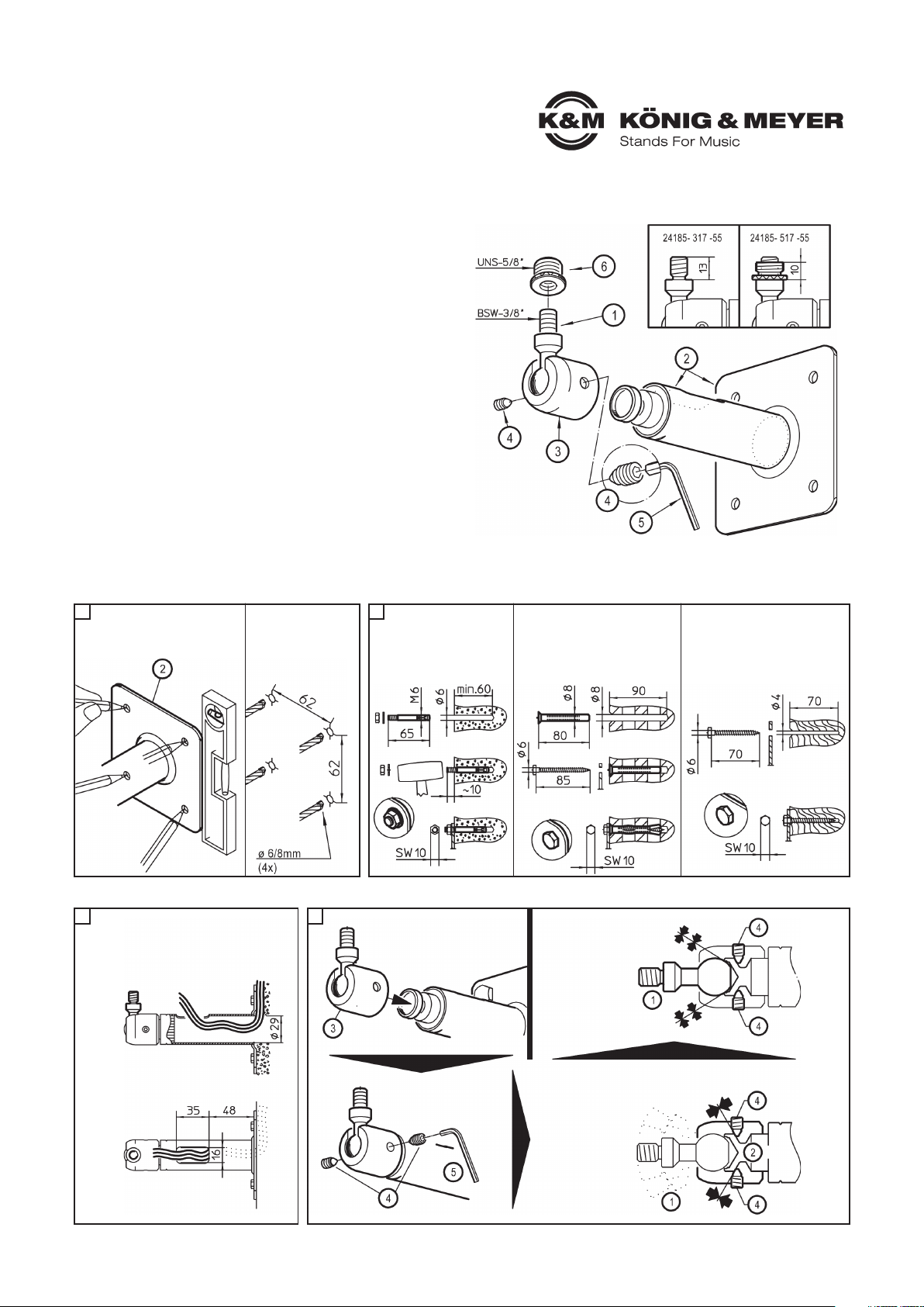
A Teile
Sichtprüfung: Sind alle Teile vorhanden und in Ordnung?
1 Gewindebolzen 3/8" / 2 Wandplatte mit Auslegerrohr
3 Gelenkkörper / 4 Gewindestift mit Spitze M6 x 10 mm (2x)
5 Inbusschlüssel SW3 für M6 / 6 Adapter 3/8” auf 5/8” (nur bei 24185-517-55)
WANDPLATTE BEFESTIGEN
LAGE DER KABELÖFFNUNG MONTAGE DES GELENKKÖRPERS UND GEWINDEBOLZENS
1. Wandplatte an geeigneter
1. Stelle platzieren und
1. senkrecht ausrichten.
2. Bohrlöcher markieren.
3. Dübellöcher bohren,
3. 4x
3. -ø 6 f. Anker-Bolzen
3. -ø 8 f. Rahmendübel
D
CB
- Tragkraft: max. 10 kg
- Nicht für Außen- bzw. Feuchträume
- Beachten Sie die örtlich gültigen Befestigungsanweisungen
- (evtl. abweichend von den Beispielen in Kapitel C)
- Benutzen Sie 4 Schrauben/Anker für die Wandbefestigung
- Montage durch ausgebildetes Installationspersonal
- Montage nur an geeigneter Wand/Decke mit entsprechendem
- Montagematerial (nicht im Lieferumfang)
- Ungeeignet sind Wände/Decken die zu schwach sind oder hinter
- denen Strom- und Wasserleitungen oder dgl. verlegt sind.
- Im Zweifel einen qualifizierten Fachmann zu Rate ziehen.
- Prüfen Sie regelmäßig die Festigkeit der Installation.
- Das Kugelgelenk ist durch zwei Gewindestifte 4 mit dem
- Halterohr verbunden; diese müssen stets fest angezogen sein
- und dürfen nur bei Neuausrichtung der Box gelockert werden.
- Dabei die Box am besten durch eine zweite Person halten
- lassen, um ein ungewolltes Wegkippen zu verhindern.
- Aufmerksame Handhabung erforderlich, da die
- Verstellmöglichkeiten Einklemmgefahren bergen
- Lautsprecher vorab auf Eignung prüfen; v.a. die Gewindebuchsen
Betonwand
Bsp.: Bolzen Anker M6 x 65 mm
aufbohren, Loch ausblasen,
Anker einschlagen, Halterung
anbringen, U-Scheiben setzen,
Muttern anziehen
Lochsteine
Bsp.: Rahmendübel 8 x 80 mm mit
Bsp.: Holzschraube 6 x 85 mm
aufbohren, senken und ausblasen,
Dübel setzen, Halterung anbringen,
Schrauben eindrehen
Holzbalken
Bsp.: Holzschraube DIN 571, 6 mm
aufbohren, senken und ausblasen,
Halterung anbringen, Schrauben
eindrehen
BEACHTE bei Unterputz-Kabel-Installation
- Öffnung Wandplatte (ø29 mm)
- Kabelausgang 35 x 16 mm
a.
Schwenkgelenk 3 über Gelenkbolzen des Auslegerrohrs schieben
c.
LOCKER angezogen, tauchen die
Gewindestifte 4 in den Einstich
des Auslegerrohres 2
ein und sichern so
den Verbleib des
Gelenkkörpers auf
dem Auslegerrohr bei gleichzeitig
beweglichem Sitz des
Gewindebolzens 1.
d. Beide Gewindestifte 4
d. per Schlüssel 5 anziehen.
d.
FEST angezogen,
bewirken die
Gewindestifte 4
einen Anpressdruck
zwischen Kugel und
Pfanne, der den
Gewindebolzen 1
in Position hält
E
Page 2
- Bei Wartungsarbeiten auf Gefährdungen achten (Klemmen etc.)
- und entsprechend sichern.
- Regelmäßig Festigkeit der Schraubverbindungen prüfen.
- Reinigen mit leicht feuchtem Tuch und nicht scheuerndem
- Reinigungsmittel.
F
H
PRÜFEN, INSTANDHALTEN, REINIGEN
F - Lautsprecher sitzt locker auf dem Gewindebolzen
B - Verschraubungen prüfen und nachziehen
B - Gewindeeinsätze der Boxen überprüfen
F - Lautsprecher hält die Position nicht
B - Gewicht des Lautsprechers prüfen (max. 10 kg)
B - Gewindestifte 4 nachziehen
FEHLERSUCHE (F) und BESEITIGUNG (B)
TECHNISCHE DATEN
Material
Rohre, Platte - Stahl, schwarz gepulvert
Gelenk - Zink-Druckguß, schwarz gepulvert
Gewindestifte, Klemmbolzen - Stahl, verzinkt
Tragelast Lautsprecher, max. 10 kg
Abmessungen
Wandplatte: 95 x 95 mm,
Tiefe: 159 mm
Gewicht 0,7 kg
KÖNIG & MEYER GmbH & Co. KG
Kiesweg 2, 97877 Wertheim, www.k-m.de
24185-317-55 / 24185-517-55 Rev.04 03-80-729-00 5/17
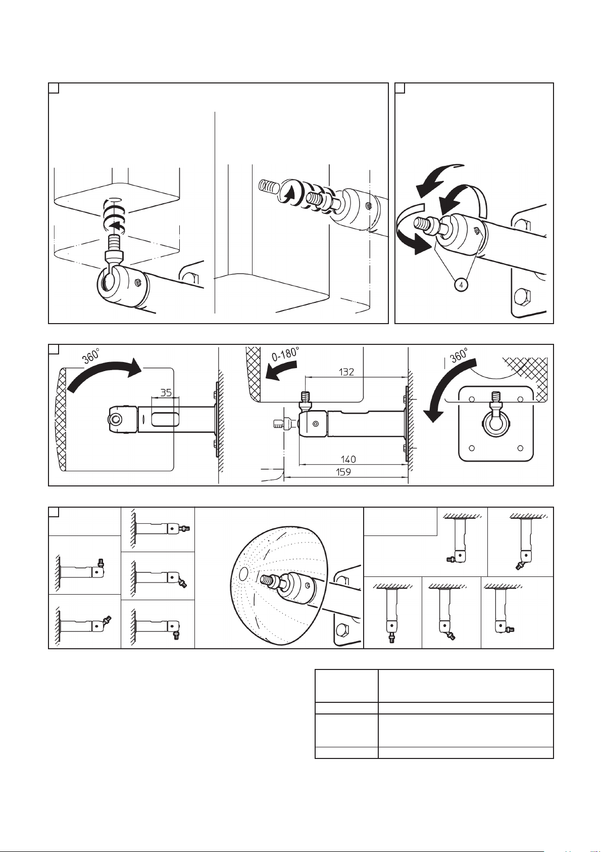
MONTAGE DES LAUTSPRECHERS
ABMESSUNGEN & VERSTELLBEREICHE
DIE HALTERUNG IN DER PRAXIS - ANWENDUNGSBEISPIELE
Stufenlos verstellbar in Richtung und Neigung.
a. Box festhalte
b. Beide Gewindestifte 4 etwas lösen,
c. Box in gewünschte Position bringen
d. Beide Gewindestifte 4 wieder festdrehen.
HINWEIS: auch hier empfiehlt es sich aus
Sicherheitsgründen zu zweit zu arbeiten.
G
LAUTSPRECHER EINSTELLEN
- vertikale Rotation:
Eingesetzt als
Deckenhalter
1. Senkrecht
1. nach oben
3. Waagerecht Das Gelenk ermöglicht es, den Gewindebolzen in
wirklich jede Position innerhalb einer 360°-Halbkugel
einzustellen.
1.
Waagerecht
links
2.
Geneigt
links
3.
Senkrecht
4.
Geneigt
rechts
5.
Waagerecht
rechts
4. Geneigt
4. nach unten
5. Senkrecht
5. nach unten
2. Geneigt
2. nach oben
- Neigung:
Neigungswinkel
linksrechts
Drehwinkel
- horizontale Rotation:
I
Eingesetzt
als Wandhalter
1. Die Box wird bis zum Anschlag* auf den FEST
1. fixierten Gewindebolzen der Halterung
1. (siehe E.d) aufgedreht.
1. Dies ist v.a. der Fall bei:
1. a. eher kleinen Boxengehäusen
1. b. am Boden der Box eingelassenen
1. b. Gewindebuchsen
2. Der LOSE fixierte Gewindebolzen (siehe E.c) wird bis
2. zum Anschlag* in die drangehaltene Box eingedreht.
2. Zumeist bei:
2. a. größeren Boxengehäusen
2. b. rückwandig angeordneten Boxen-Gewindebuchsen
HINWEIS: Aus Sicherheitsgründen empfehlen wir mit zwei Personen zu arbeiten: eine für die Box, eine für den
Gewindebolzen.
Um den Lautsprecher mit dem Gewindebolzen zu verschrauben bieten sich zwei Vorgehensweisen an:
* Das Schrauben bis zum Anschlag führt bisweilen zu schief sitzenden Boxen. Dies wird korrigiert wie in Kap. G beschrieben.
Page 3

24185 Speaker wall/ceiling mount
- adjustable to any angle by special swivel joint assembly
SAFETY INSTRUCTIONS
INSTRUCTIONS
A PARTS
Are all listed parts in the delivery and in working order?
1 Threaded bolt 3/8" / 2 Wall plate with support tube
3 Joint / 4 Pointed threaded pin M6 x 10 mm (2x)
5 Allen wrench SW3 for M6 / 6 Adapter 3/8” to 5/8” (only for 24185-517-55)
POSTION OF THE CABLE OPENING MOUNT THE JOINT AND THREADED BOLT
D
- load bearing weight: max 10 kg
- not suitable for outdoors or moist rooms
- please refer to local mounting instructions
- (may possibly deviate from the examples provided in Section C)
- use 4 screws/anchors for the wall mount
- only use trained technicians to install the system
- only mount on suitable walls with the corresponding
- mounting materials (not included in the delivery)
- walls, that are too weak or have electrical and water conduits are
- not suitable. In case of doubt consult a qualified technician.
- Check the stability of the installation regularly.
- The universal ball joint is connected to the holding tube with two threaded
- pins 4 and may only be loosened when changing the position of the
- loudspeaker. In this process it is best to have two people hold the
- loudspeaker to ensure that it does not dislodge.
- Careful and attentive handling is required when adjusting the
- loudspeakers, due to the possibility of pinching or wedging of
- your hand.
- Check to ensure that the loudspeaker is suitable; particularly the
- threaded bushings.
NOTE for in-wall-cable-installation
- Wall plate opening (ø29 mm)
- Cable exit - 35 x 16 mm
a.
Place the joint 3 over the support
tube pivot bolt
c.
LIGHTLY tightened, the threaded
pins 4 are placed into the holes in
the support tube 2
and secure the
placement of the
joint on the support
tube bolt while
simultaneously
ensuring the movable
fit of the threaded
bolts 1.
d. Tighten both threaded
d. pins 4 with the Allen
d. wrench 5.
d.
TIGHTENDED, the pressure
asserted by the threaded
pins 4 between the joint and
socket holds the
threaded bolt 1
in position
E
ATTACH WALL PLATE TO THE WALL
1. Find a location on the wall
1. where you wish to mount the wall
1. plate, ensuring that it is vertical.
2. Mark the drill holes.
3. Drill the holes for the
3. wall plugs, 4x
3. -ø 6 for anchor bolts
3. -ø 8 for dowels
B C
concrete wall perforated bricks wood wall
2. a. For installation into stone or masonary walls, use an appropriate wall anchor (not supplied).
2. b. For installation on a wood or plaster wall, it is recommended that the wall adapter be attached
2. b. to a supporting wall stud, or other suitable support. The two Center holes in the wall plate can
2. b. be used for a stud wall installation.
Page 4

- During maintenance work, watch out for possible injuries
- Inspect bolted assemblies regularly
- For cleaning it is best to use a damp cloth an a mild,
- nonabrasive detergent.
F
H
CHECKING, MAINTENANCE, CLEANING
F - Speaker sits loosely of the threaded bolt
R - Check screws, if needed tighten screws
R - Check the threaded inserts of the loudspeakers
F - The loudspeaker does not stay in its position
R - Check the weight of the loudspeaker (max. 10 kg)
R - Tighten threaded pins 4
FAULT FINDING (F) and REPAIR (R)
TECHNISCHE DATEN
Material
Tubes, Plates - steel, black powder coated
swivel joint - zinc die-cast, black powder coated
Gewindestifte, Klemmbolzen - Stahl, verzinkt
Load Speaker, max. 10 kg
Dimensions
Wall plate: 95 x 95 mm,
Depth: 159 mm
Weight 0.7 kg
KÖNIG & MEYER GmbH & Co. KG
Kiesweg 2, 97877 Wertheim, www.k-m.de
24185-317-55 / 24185-517-55 Rev.04 03-80-729-00 5/17
SPEAKER MOUNTING
DIMENSIONS & SETTINGS
THE MOUNT IN DAY TO DAY USE - APPLICATION EXAMPLES
Var ia ble ad ju stm en ts bot h for a ngl e a nd di re cti on .
a. Hold the loudspeaker
b. loosen both threaded pins 4 somewhat,
c. Place the loudspeaker in the desired position
d. Re-tighten both threaded pins.
NOTE: For safety reasons ensure
that two people perform this work.
G
SPEAKER ADJUSTING
- vertical rotation:
Used as a
ceiling mount
1. Vertical
1. upwards
3. Horizontal The joint allows one to adjust the threaded bolts in
virtually every position within a 360°-joint head.
1.
Horizontal
left
2.
Angled
left
3.
Vertical
4.
Angled
right
5.
Horizontal
right
4. Angled
4. downwards
5. Vertical
5. downwards
2. Angled
2. upwards
- angle: - horizontal rotation:
I
Used as a
wall mount
1. The loudspeaker is screwed in as far as it will
1. go* on the fixed threaded bolt of the mount
1. (refer to E.d).
1. This is particularly the case if:
1. a. smaller loudspeaker housings
1. b. the floor of the box has sunken-in
1. b. threaded bushings
2. The LOOSE fixed threaded bolts (refer to E.c) are
2. screwed as far as they will go* into the loudspeaker
2. Usually with:
2. a. larger loudspeaker housings
2. b. loudspeaker threaded bushings are located on
2. b. the back wall
NOTE: For safety reasons ensure that two people perform this work: one for the loudspeaker and one for the
threaded bolts.
To connect the loudspeaker to the threaded bolts we offer the following two options:
* Screwing it in as far as it will go can result in loudspeakers that are not squared up properly. The way to correct this is described in Section G.
inclination
angle
leftright
rotation
angle
 Loading...