

Page 1
HDS 995 M Eco HDS 995 MX Eco
HDS 1295 S Eco HDS 1295 SX Eco
www.kaercher.com 5.961-300 A2008544 05/04
Page 2

Deutsch
7
Magyar
198
English
Français
Italiano
Nederlands
Español
Português
ЕллЮнйкЬ
ЕллЮнйкЬ
ЕллЮнйкЬЕллЮнйкЬ
Dansk
23
38
55
72
88
104
120
138
Česky
Slovensko
Polska
Româneşte
Türkçe
Русский
Slovensky
Hrvatski
214
230
246
263
280
296
314
330
Norsk
Svenska
Suomi
2
153
168
183
Srpski
Български
346
362
Page 3

-
Page 4
1
5
2
3
4
6a
6b
7
Page 5
8
11b
9
10
11a
12
13
14
Page 6
15
16
17
19
18
Page 7
Operating Instructions English
Contents
Warning!
Environmental protection 23
Unit illustration 24
Prior to initial operation it is mandatory to
read the operating instructions and the
notes on safety no. 5.951-949!
Operating controls 24
Reference to operating
instructions 25
Commissioning 25
Operation 27
After every operation 29
Decommissioning 30
Maintenance 30
Maintenance tasks 31
Faults 32
Warranty 35
General notes 35
EC conformity declaration 36
Technical data 37
Parts list 379
Inform retailer immediately of any
transportation damage.
Environmental protection
Please dispose of packaging
environmentally responsibly
The packaging materials are recyclable.
Please do not throw the packaging in with
household rubbish but take it to a recycling
centre.
Please dispose of scrapped units
environmentally-responsibly
Scrapped units consist of valuable
recyclable materials that should be taken to
a recycling centre. Batteries, oil and similar
products must not be allowed to
contaminate the environment. Therefore,
please dispose of scrapped units via
appropriate disposal systems.
Danger: Steam!
Danger of scalding! Steam escapes here.
Please ensure engine oil, fuel oil, diesel
and petrol
to contaminate the environment. Please
protect the ground and dispose of used oil
ecologically.
23
Page 8

English Operating Instructions
Unit illustration
Operating controls
1 Fuel tank inlet
2 Handle
3 Instrument panel
4 Window with the
maintenance/fault display
5 Cover latch
6 Compartment für accessories
7 Short operating instructions
8 Cover for compartment
9 Unit cover
10 Cover for tank inlet
11 Tank inlet für scale inhibitor
12 tank inlet for cleaning agent
13 High-pressure nozzle
14 Handle grips in the chassis
15 Steel pipe
16 Pressure and flow control
17 Swivel caster with parking brake
18 Water connection with strainer
19 High-pressure connection
20 Handgun with high-pressure hose
22 Electric power cord
23 Unit switch
24 Temperature regulator
25 Fuel indicator lamp
26 Scale inhibitor indicator lamp
27 CHEM1, CHEM2 indicator lamp
(applies only to HDS 1295)
28 Engine/electronics indicator lamp
29 Ready for working indicator lamp
30 Pressure gauge
31 Metering valve for cleaning agent
32 Hose reel (applies only to MX/SX)
33 Crank (applies only to MX/SX)
34 Fine filter
24
Page 9

Operating Instructions English
Reference to operating
instructions
All of the item numbers described below in
the operating instructions are referenced in
the illustration of the unit.
Commissioning
Warning!
Unit, piping, high-pressure hose and
connections must be in perfect working
order!
! Lock the hand brake.
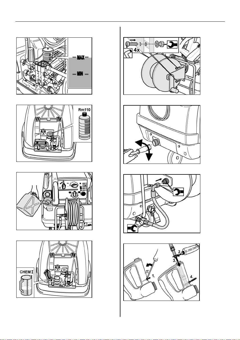
Checking oil level
Fig. 1
Warning!
Immediately consult the Kärcher service
station when oil turns milky!
! If oil level is approaching MIN mark, fill
up with oil as far as MAX mark.
! Seal oil filler inlet.
Refer to technical data for oil grade.
Filling with scale inhibitor
Fig. 2
! For other water hardnesses request
services of a Kärcher service station and
have it adapted to local conditions.
Filling with fuel
Warning!
Never operate unit with fuel tank empty!
Fuel pump would otherwise be destroyed!
Warning!
Fig. 3
Only fill with diesel fuel or light fuel oil.
It is forbidden to use unsuitable fuels,
e.g. benzine (explosion hazard, damage to
unit).
! Close tank cap
! Wipe off excess fuel
Fill with cleaning agent
— Use only Kärcher products.
— Never pour in solvent (petrol, acetone,
thinner etc.)!
— Avoid contact with eyes and skin
— Pay attention to cleaning-agent
manufacturer's instructions on safety
and handling
(sample pack included with scope of
delivery)
Scale inhibitor stops heating coil becoming
calcified when using hard tap water. Is is
metered in at the inlet in the water reservoir
one drop at a time.
By the manufacturer metering is set to a
mean water hardness.
Kärcher offers a customised cleaning
and care agent range.
Your dealer will be pleased to advise you.
Fig. 4
Fill with cleaning agent
25
Page 10

English Operating Instructions
Installing the handgun (units
without hose reel)
! Connect steel pipe (item 15) with
handgun (item 20)
! Insert high-pressure nozzle in union nut
! Mount and tighten unit nut
! Install the high-pressure hose to high-
pressure connection of unit. (Figure 6a)
Installing the handgun and the
hose reel (units with hose reel)
! Connect steel pipe (item 15) with
handgun (item 20)
! Insert high-pressure nozzle in union nut
! Mount and tighten unit nut
! Install the hose reel (item 32) with the
provided Allen screws, washers and
nuts (4 of each). (Figure 5)
! Install the high-pressure hose at the
high-pressure connection of hose reel
and unit. (Figure 6b)
! Connect high-pressure hose of handgun
to hose reel
! Wind high-pressure hose onto hose reel
with the smallest possible bends
(direction of turns – clockwise -)
Drawing in water from tank
When you suction water out of an open
container you should
! remove water connection at pump head.
! screw off the top supply hose with the
fine filter to the water tank and connect
to pump head.
! Use a water suction hose with a suction
filter and a diameter of at least 3/4".
Until the pump sucks up water you should:
! Turn the pressure and flow control to
"MAX".
! close the metering valve for the cleaning
agent.
Warning!
Never suction up water out of a potable
water tank.
Never suction up solvent-bearing liquids
such as paint thinner, benzine, oil or
unfiltered water. The seals in the unit are
not resistant to solvents. The mist of
solvents is highly inflammable, explosive
and poisonous!
Mounting of spare high-pressure
hose
Fig. 7
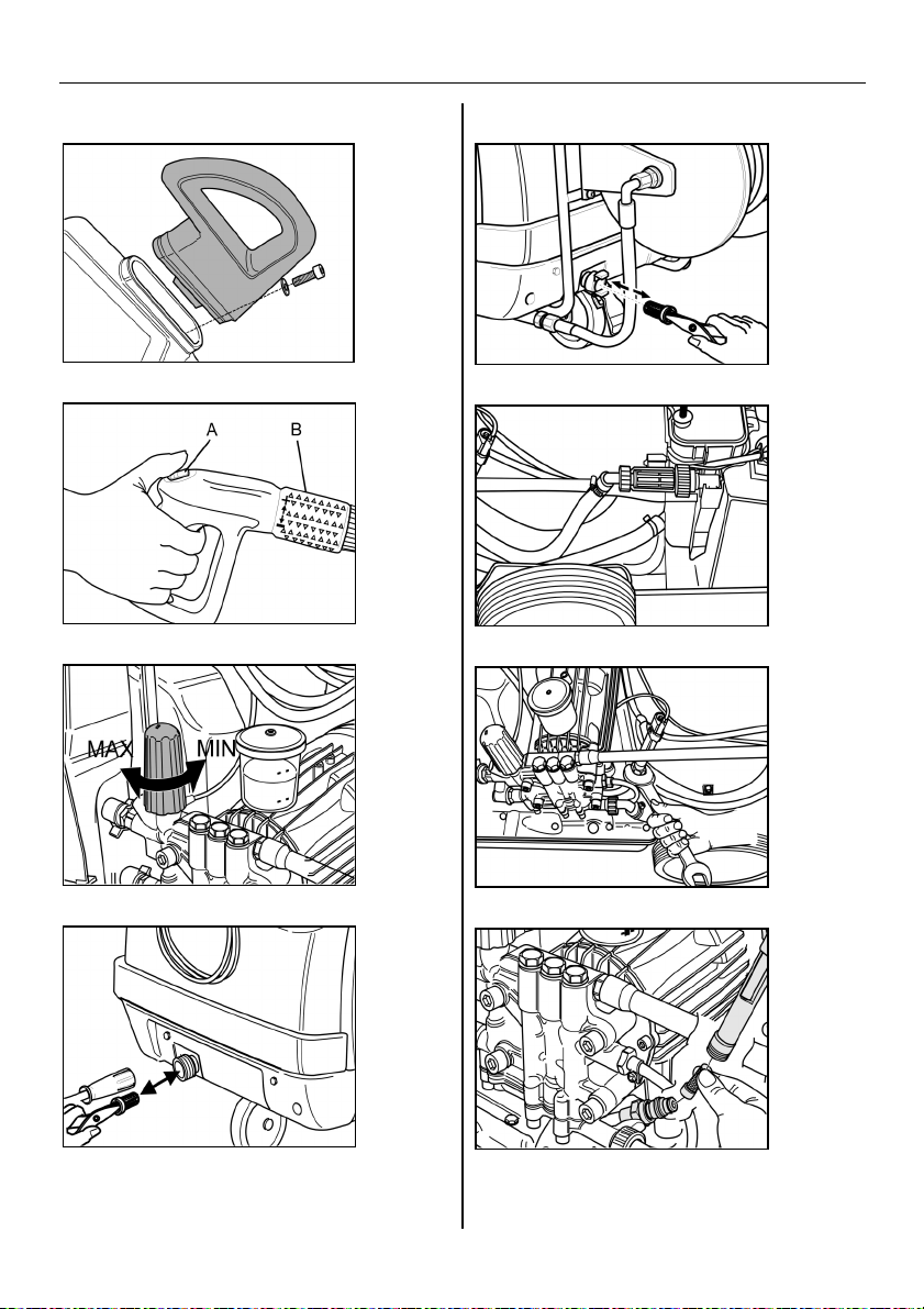
Mounting handle
Fig. 8
Water connection
! See Technical Data for connected loads.
! Install supply hose at water connection
(item 18) of unit.
(supply hose is not part of scope of
delivery)
26
Mains connection
See technical data and rating plate for
connected load.
Warning!
It is not permissible to exceed the
maximum permissible mains impedance at
the electrical terminal (see Technical Data).
Warning!
Whenever socket is changed, check
direction of rotation of motor
Page 11

Operating Instructions English
— If direction of rotation is correct, powerful
jet of air will be felt at exhaust-gas
opening of burner.
— If the direction of rotation is
wrong: Change the poles at the unit
plug. See Fig. 18.
! When an extension cable is used it
should always be complety unwound
and have an adequate cross-section.
Operation
Switch on the machine
! Set unit switch (item 23) to "I"
Ready for working indicator lamp (item 29)
is lit
Warning!
The temperature regulator (item 24) must
be set to "0", since otherwise the burner
possibly switches on
Unit starts up briefly and is switched off as
soon as operating pressure is reached.
Stop the unit immediately when one of the
indicator lamps (items 25-28) light up
during operation. Eliminate fault, refer to
Faults.
Fig. 9
! Release the safety of the handgun (A)
Actuation of handgun switches unit back on
again.
Setting cleaning temperature
! Set the remperature regulator (item 24)
to the required temperature
30°C to 90°C
Hot water cleaning
100°C to 150°C
Cleaning with steam
! Replace high-pressure nozzle by the
steam nozzle (see operation using
steam)
Setting operating pressure and
flow rate
Fig. 10
— Turning control spindle
clockwise: Increasing operating pressure
(MAX)
— Turning it counterclockwise: Reducing
operating pressure (MIN)
Servopress control
! Set the temperature regulator (item 24)
to max. 98°C.
! Set regulator to maximum operating
pressure.
Fig. 9
Adjust operating pressure and flow rate by
turning (infinitely variable) at the pressure
and flow control (B) (+/-)
Set pressure on unit if use is to be made of
reduced pressure for a lengthy period.
See Fig. 10
Bleed pump if no water emerges from highpressure nozzle. See problems, "Unit does
not build up pressure"
27
Page 12

English Operating Instructions
Measuring out cleaning agents
— Use cleaning agents sparingly to protect
the environment
— The cleaning agent must be appropriate
for the surface to be cleaned.
! Using the cleaning agent metering valve
(item 31) set the concentration of the
cleaning agent as specified by the
manufacturer
Approximate values at maximum operating
pressure
Intended use
For cleaning: machines, vehicles, buildings,
tools, facades, patios, gardening
implements, etc.
Warning!
— Heed appropriate safety regulations for
use at petrol stations or in other
hazardous environments.
Please ensure waste water containing
mineral oil
does not contaminate soil, lakes and rivers
or the sewerage system. Therefore, please
wash engines and underbodies only in
appropriate washing installations provided
with oil traps.
Working with high-pressure nozzle
Spray angle is crucial to efficiency of highpressure jet.
Use is normally made of 25°fan jet nozzle
(included).
Recommended nozzles, available as
accessories
— For stubborn dirt
0°full jet nozzle
— For sensitive surfaces and superficial
dirt
40°-fan jet nozzle
— For thick-film, stubborn dirt
Dirt blaster
— Nozzle with adjustable spray angle,
adaptable to many cleaning tasks
Variable-angle nozzle
Cleaning
! Set pressure/temperature and detergent
concentration appropriately to surface to
be cleaned
Always start by directing high-pressure jet
from a good distance at object to be
cleaned to avoid damage caused by
excessive pressure.
Recommended cleaning method
Loosen up dirt:
! Spray on cleaning agent sparingly and
allow to react for 1...5 min (do not allow
to dry on).
Remove dirt:
! Spray off loosened-up dirt with high-
pressure jet.
Operation with cold water
Removal of slight contamination and rinsing
e.g: gardening implements, patio, tools, etc.
28
! Set operating pressure as required
! Set temperature control (item 24) to "0"
Page 13

Operating Instructions English
Operation with hot water
Warning!
Danger of scalding
! Set the remperature regulator (item 24)
to the required temperature
We recommend the following cleaning
temperatures
— Slight contamination 30-50°C
— Protein soiling, e.g. in foodstuffs industry
max. 60°C
— Motor vehicle cleaning, machine
cleaning 60-90°C
Safety deactivation
If the handgun is not opened or closed for
more than 30 minutes, for safety reasons
the pump switches off automatically.
— To switch it on again turn the main
switch to "0" and then back to "I".
(EPROM without shut down 6.682-595
available from service)
! Set operating pressure to minimum
value. See Fig. 10
! Set the temperature regulator (item 24)
to min. 100°C
Danger: Steam!
Danger of scalding!
We recommend the following cleaning
temperatures
— Preservative removal, extremely greasy
dirt 100-110°C
— Thawing of aggregates, certain facade
cleaning operations up to 140°C
After every operation
Warning!
Danger of scalding with hot water.
After operating it with hot water or steam, to
cool it the unit must be operated at least
two minutes with cold water with an open
handgun.
Operation with steam
Danger: Steam!
At operating temperatures above 98°C
operating pressure must not exceed 32 bar
(HDS 1295: 28 bar).
Therefore the following steps must be
taken without fail:
! Replace high-pressure nozzle by steam
nozzle
Manufacture no.:
4.766-023 HDS 995
4.766-024 HDS 1295
! Fully open water delivery control at the
handgun, in the + direction to the stop.
See Figure 9 (B)
Following operation with cleaning agent
! Set cleaning agent metering valve
(item 31) to "0"
! Set unit switch (item 23) to "I"
! Actuate handgun and flush unit for
approx. 1 min
Stopping machine
! Set unit switch (item 23) to "0"
! Shut off water supply
! Switch the pump briefly on with the unit
switch (item 23) (approx. 5 sec.)
! Remove mains plug from socket ONLY
with dry hands
! Remove water connection
! Actuate handgun to depressurise unit
! Put on safety of handgun Figure 9 (A)
! Engage spray lance in cover holder
29
Page 14

English Operating Instructions
! Reel up the high-pressure hose and
electric cables and attach them to
fastenings
Note!
Take care not to kink high-pressure hose
and cable!
Note!
Frost will destroy unit if water is not drained
off completely!
! Store unit in a frost-free location
Observe the following if the unit is
connected to a flue:
Danger of damage caused by cold air
entering through the flue. Disconnect unit
from flue at outside temperatures below
0°C.
Immobilise unit if frost-proof storage is not
possible.
Decommissioning
In the event of lengthy periods of non-use
or if frost-free storage is not possible:
! Drain off water and flush out equipment
with antifreeze
! Drain cleaning fluid tank
Drain off water
! Unscrew water supply hose and high-
pressure hose
! Screw off supply line at boiler base and
completely drain heating coil
! Run unit for max. 1 min until pump and
lines are empty
Flushing unit with anti-freeze
! Fill the float tank with a commercially
available antifreezing compound
! Swith the unit on (without the burner)
until it is thoroughly purged
! Observe handling instructions of
antifreeze manufacturer
By this means, a certain degree of
corrosion protection is achieved
Maintenance
Warning!
Disconnect unit from mains before carrying
out any maintenance or repair work.
Always use genuine spare parts
Turn off unit prior to all work, see "After
every operation".
! Set unit switch (item 23) to "0"
! Pull power plug out of socket
! Shut off water supply
! Actuate handgun to depressurise unit.
! Remove water connection
! Allow unit to cool down
Your Kärcher dealer will be pleased to
inform you on the performance of
regular safety inspections
and conclusion of a maintenance
contract
30
Page 15

Operating Instructions English
Maintenance intervals
Once a week
— Clean strainer in water connection
— Clean the fine filter
— Check oil level
Immediately consult the Kärcher service
station when oil turns milky!
Once a month
— Clean strainer in low water protection
— Clean filter at cleaning-agent suction
hose
After 500 hours of operation, at least
once a year
— Change oil
Maintenance tasks
Engine/electronics indicator
lamp (item 28) is lit
— This warning lamp lights up when certain
maintenance work is necessary due to
accumulated operating hours.
! When you open the cover (item 8) of
the compartment (item 6) the electronic
display is visible in the window (item 4).
! When the necessary maintenance work
has been completed you should depress
the RESET button next to the display for
at least 7 seconds until the warning lamp
goes out.
Display
Necessary maintenance work
! Visual inspection
! Check that the high-pressure
connections do not leak
! Clean the fuel tank and the filter
Display
Necessary maintenance work
! Check that the pump does not leak
! Change the pump's oil
! Clean strainer in water connection
! Clean the strainer (coarse) fitted in front
of the low water protection
Display
Necessary maintenance work
! Decarbonise the heating coil *
! Descale the heating coil *
! Clean/replace the ignition electrodes *
! Cleaning/replacing the burner nozzle *
! Adjust the burner *
Display
Necessary maintenance work
! Check the overflow valve for leaks *
! Check the high-pressure hose *
! Clean the handgun
! Check the pulsation damper *
* This maintenance work should be
performed only by after-sales service.
31
Page 16

English Operating Instructions
Clean strainer in water
connection
Fig. 11
! Remove strainer
! Clean in water and re-insert
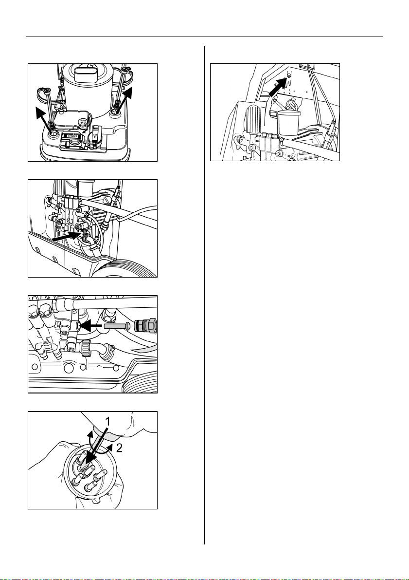
Clean the fine filter
Fig. 12
! Cut pressure to unit
! Screw off cover with filter
! Clean filter with clean water or with
compressed air
! Assemble in the reverse order
Clean strainer in low water
protection
Fig. 13
! Unfasten union nut and detach hose
Fig. 14
! Take out strainer
If necessary, screw-in screw M8 by
approx. 5 mm and pull out the strainer with
this screw
! Clean strainer in water
! Slide in strainer
! Mount hose
! Tighten union nut
Clean filter at cleaning-agent
suction hose
Fig. 15
! Pull the cleaning agent suction inlet pipe
out
! Clean filter in water and re-insert
Change oil
Fig. 16
! Provide a collecting container for
approx. 1 litres of oil
! Unscrew drain plug
Dispose of used oil ecologically or hand it
in at a dump.
! Retighten drain plug
! Top up oil slowly up to the MAX mark
Air bubbles must be able to escape
Refer to technical data for oil grade and
quantity to be used.
Faults
Engine/electronics indicator lamp
(item 28) flashes
— This warning lamp flashes if there is a
problem.
! When you open the cover (item 8) of the
compartment (item 6) the electronic
display is visible in the window (item 4).
! The warning lamp goes out when the
problem has been resolved and the unit
is switched on again.
Display
Troubleshooting
! Increase the water inlet volume
! Clean strainer in water connection
! Clean the strainer (coarse) fitted in front
of the low water protection
32
Page 17

Operating Instructions English
Display
Troubleshooting
! Replace the reed switch for the low
water protection *
! Clean the low water protection *
Display
Troubleshooting
! Eliminate the leakage in the high-
pressure system
Display
Troubleshooting
Motor overloaded/overheated
! Turn monitoring switch to "0" and allow
engine to cool for at least 5 min
! Have unit checked by After-Sales
Service if this does not remedy fault
! Cbeck exhaust gas temperature limiter,
reset, if necessary (Figure 19)
Display
Troubleshooting
! This error code appears only on units
equipped with the – accessory kit flame
monitoring system ! See the assembly instructions –
accessory kit flame monitoring system -
* This maintenance work should be
performed only by after-sales service.
Ready for working indicator lamp
(item 29) goes out
— Motor overloaded/overheated
! Set selector switch to "0" and allow
engine to cool off for at least 5 min.
! Have unit checked by After-Sales
Service if this does not remedy fault.
! No mains voltage
(see – unit does not run -)
Fuel indicator lamp (item 25) lights up
— Fuel tank empty
! Fill up
Liquid softener indicator lamp (item 26)
lights up
— Scale inhibitor reservoir empty; for
technical reasons there is always a
residual quantity in the reservoir.
! Fill up
— Dirt on electrodes in reservoir
! Clean electrodes
Unit does not run
— No mains voltage
! Check electric mains/power cord
Unit does not build up pressure
— Air in system
Bleed pump:
! Set cleaning agent metering valve
(item 31) to "0"
! Switch the unit switch on and off several
times keeping the handgun open.
! With handgun open, open and close
regulator (Fig. 10).
Venting is accelerated by removing the
high-pressure hose from the high-pressure
connection.
33
Page 18

English Operating Instructions
! Fill up cleaning-agent tank if empty.
! Check connections and lines
— Pressure set to MIN
! Set pressure to MAX
— Strainer in water connection is dirty
! Clean strainer
! Clean fine filter, replace it if necessary
— Insufficient water supply
! Check water supply volume (refer to
technical data)
Unit leaking, water dripping out at
bottom
— Pump leaking
3 droplets/min are permitted.
! In the event of a major leak, have unit
checked by After-Sales Service.
Unit constantly switched on and off with
handgun closed
— Leak in high-pressure system
! Check high-pressure system and
connections for leaks
Unit does not draw in cleaning agent
! Run the unit with an opened cleaning
agent metering valve and a closed water
supply until the float tank is sucked dry
and the pressure drops to "0".
! Now reopen the water inlet.
If the pump still does not suction up
cleaning agent the reasons can be as
follows:
— Filter in cleaning-agent suction hose
dirty
! Clean filter
Burner not ignited
— Fuel tank empty
! Fill up
— Lack of water
! Check water connection, check supply,
clean low water protection.
— Fuel filter is dirty
! Replace fuel filter.
— Incorrect direction of rotation. If direction
of rotation is correct, powerful jet of air
will be felt at exhaust-gas opening of
burner.
! Check direction of rotation. If necessary,
change round poles of unit plug. See
Fig. 18.
— No ignition spark
! Have unit checked by After-Sales
Service if no ignition spark is visible
through inspection glass during
operation.
Set temperature not attained when
working with hot water
— Excessive operating pressure/flow rate
! Reduce operating pressure/flow rate by
way of regulator (Fig. 10)
— Soot deposits on heating coil
! Have After-Sales Service remove soot
deposits from unit
The unit must be checked by after sales
service if the problem cannot be
remedied.
— Non-return valve gummed up
! Pull the cleaning agent hose off and
detach the non-return valve with a blunt
object, see Figure 17.
34
Page 19

Operating Instructions English
Warranty
The warranty terms and conditions issued
by our responsible sales company apply in
every country. Within the warranty period,
any faults in the unit will be rectified free of
charge provided that the problem was
caused by a material defect or
manufacturing error.
The warranty only applies if the dealer fills
in, stamps and signs the enclosed reply
card when the unit is sold and the
purchaser then returns it to the appropriate
local distributor.
In the event of a warranty claim, please
contact your dealer or the nearest
authorised After-Sales Service office and
produce both accessories and proof of
purchase.
General notes
Safety features
Overflow valve with two pressure
switches
— When reducing water volume at pump
head or with the servopress control, the
overflow valve will open and part of the
water will flow back to the pump suction
side.
— If the handgun is closed off so that all
the water flows back to the pump suction
side, the pressure switch at the overflow
valve turns off the pump.
— Reopening the handgun causes the
pressure switch at the cylinder head to
switch the pump back on again.
The overflow valve is set at the factory and
lead-sealed. Adjustment can only be made
by After-Sales Service.
Safety valve
— The safety valve opens if the overflow
valve or pressure switch is defective.
The safety valve is set at the factory and
sealed. Adjustment can only be made by
After-Sales Service.
Low water protection
— The low water protection prevents the
burner switching on when water is
insufficient.
— A strainer prevents dirt accumulation on
the protection and must be regularly
cleaned.
Motor protection switch
— The motor protection switch interrupts
the circuit should overloading occur.
Switching on procedures
— Switching on procedures generate brief
voltage drops.
— Impairments of other appliances can
occur in cases of unfavourable mains
conditions.
— No problems are to be expected with a
mains impedance of less than 0,15 ohm.
35
Page 20

English Operating Instructions
EC conformity declaration
We hereby declare that the machine
specified below as the marketed desigh,
the machine specified below complies with
the relevant fundamental safety and health
requirements of the EC directives listed
below.
Modification of the machine without our
approval invalidates this declaration.
Product: High-pressure cleaner
with a steam stage
Type: 1.027-xxx, 1.028-xxx
Relevant EC directives
EC machine directive (98/37/EC)
EC low voltage directive (73/23/EEC)
amended by 93/68/EEC
EC directive on electromagnetic
compatability (89/336/EEC) amended by
91/263/EEC, 92/31/EEC, 93/68/EEC
EC high-pressure equipment directive
(97/23/EG)
EC guideline on noise emissions
(2000/14/EU)
Applied harmonised standards
DIN EN 60335-1
DIN EN 60335-2-79
DIN EN 55014-1:2000 + A1:2001
DIN EN 55014-2:1997
DIN EN 61000-3-2:2000
DIN EN 61000-3-3:1995 + A1:2001
(HDS 995)
DIN EN 61000-3-11:2000 (HDS 1295)
Measured sound power level:
HDS 995 89 dB(A)
HDS 1295 88 dB(A)
Guaranteed sound power level:
HDS 995 91 dB(A)
HDS 1295 89 dB(A)
Internal measures ensure that the in series
produced units always comply with the
requirements of current EC directives and
applied standards. The signatories act for
and in authority of management.
5.957-649 (02/04)
Alfred Kärcher Limited Partnership.
Registered office: Winnenden. Registration
court: Waiblingen, HRA 169.
Personally liable partner. Kärcher
Reinigungstechnik GmbH. Registered
office Winnenden, 2404 Waiblingen
Company Register, HRB
Managing directors:
Dr. Bernhard Graf, Hartmut Jenner,
Georg Metz
Alfred Kärcher GmbH & Co. KG
Cleaning Systems
Alfred-Kärcher-Strasse 28-40
P.O.Box 160
D-71349 Winnenden
Phone: ++49 7195 14-0
Fax :++49 7195 14-2212
Applied national standards
---
Applied conformity valuation method
Appendix V
36
Page 21

230 V
3~50 Hz
400 V
3~50 Hz
230 V
3~50 Hz
3~50 Hz
Type HDS 995 M / MX Eco HDS 1295 S / SX Eco
Mains connection 400 V
Technical Data English
Connected load 6,8 kW 6,8 kW 8,2 kW 8,2 kW
Fuse (slow blow) 16 A 25 A 16 A 35 A
Maximum permissible mains impedance --- --- (0,307+j 0,192) Ω (0,307+j 0,192) Ω
Water connection
Supply temperature max. 30 °C max. 30 °C
Supply volume min. 1200 l/h (20 l/min) min. 1500 l/h (25 l/min)
Suction height when drawn
from open tank (at 20°C water temperature) 0,5 m 0,5 m
Performance data
Flow rate: cold/hot water 470-1000 l/h (7,8-16,7 l/min) 600-1200 l/h (10-20 l/min)
Operating pressure: cold/hot water (with standard nozzle supplied) 3-18 MPa (30-180 bar) 3-18 MPa (30-180 bar)
Flow rate: steam 470 l/h (7,8 l/min) 600 l/h (10 l/min)
Operating pressure: steam max. 3,2 MPa (32 bar) max. 2,8 MPa (28 bar)
Steam nozzle part number 4.766-023 4.766-024
Operating temperature
- Hot water max. 95 °C max. 95 °C
- Steam 98-155 °C 98-155 °C
Cleaning-agent intake 0 - 40 l/h (0-0,7 l/min) 0 - 48 l/h (0-0,8 l/min)
Burner output 86 kW 103 kW
Maximum fuel oil consumption 6,9 kg/h 8,3 kg/h
Recoil force of handgun 43 N 60 N
Noise emission
Sound pressure level (EN 60704-1) 75 dB (A) 73 dB (A)
Guaranteed sound power level (2000/14/EC) 91 dB (A) 89 dB (A)
Machine vibration
Rated vibration value (ISO 5349)
Handgun 2,5 m/s² 1,7 m/s²
Spray lance 1,8 m/s² 1,7 m/s²
Fuels
Fuel Heizöl EL oder Diesel Heizöl EL oder Diesel
Oil quantity 0,75 l 0,75 l
Oil grade Hypoid SAE90 (6.288-016) Hypoid SAE90 (6.288-016)
Dimensions and weights
Length x Width x Height 1285x690x835 mm 1285x690x875 mm
Weight not incl. accessories 133 kg 155 kg
Weight not incl. accessories, MX Eco / SX Eco 141 kg 163 kg
Fuel tank 25 l 25 l
Cleaning-agent tank 20 l 20 + 17 l
37
Page 22

379
Page 23

380
 Loading...