

KZTech iSurf 1004, iSurf 1008 User Manuals

iSurfTM 1004/1008
Integrated Access Device
User Manual
KZ BROADBAND TECHNOLOGIES, LTD. C
ONFIDENTIAL
This document and the information contained in it is confidential information of KZ Broadband Technologies
Ltd (KZTech), and shall not be used, or publish, or disclosed, or disseminated outside of KZTech in whole or
in part without KZTech’s consent. This document contains trade secrets of KZTech. Reverse engineering of
any or all of the information in document is prohibited. The copyright notice does not imply publication of
this document.
© C
OPYRIGHT 2006, KZ Broadband Technologies, Ltd.
CONFIDENTIAL INFORMATION
Information contained herein is proprietary to KZTech for whose benefit
confidentiality shall be maintained.
iSurf 1004/1008 User Manuals
Page II
Revision History
Version Date Author Description
1.0 June 20,2006 KZ Broadband Technologies Initial Release
1.1 Nov. 8, 2006 KZ Broadband Technologies Removal of Encryption Feature

iSurf 1004/1008 User Manuals
Page III
Table of Contents
1 INTRODUCTION....................................................................................................................1
2 PRODUCT SPECIFICATIONS............................................................................................... 2
2.1 P
RODUCT LAYOUT ............................................................................................................ 2
2.1.1 Top Panel.................................................................................................................... 2
2.1.2 Rear Panel .................................................................................................................. 3
2.2 P
HYSICAL SPECIFICATION.................................................................................................. 4
2.3 D
ATA NETWORK FEATURES................................................................................................ 4
2.4 V
OICE FEATURES.............................................................................................................. 5
2.5 M
ANAGEMENT FEATURES.................................................................................................. 6
3 GETTING STARTED ............................................................................................................. 7
3.1 P
ACKING LIST.................................................................................................................... 7
3.2 CONNECTING OTHER CUSTOMER PREMISE DEVICES........................................................... 7
3.3 E
XAMPLE CONFIGURATION ................................................................................................ 8
3.3.1 Establish Network Connectivity................................................................................... 9
3.3.2 Example SIP Configuration ....................................................................................... 10
4 MANAGING ISURF............................................................................................................. 13
4.1 M
ANAGING ISURF VIA CONSOLE....................................................................................... 13
4.2 MANAGING ISURF BY TELNET ACCESS.............................................................................. 16
4.2.1 Telnet Access to iSurf from LAN Segment.................................................................17
4.2.2 T elnet Access from WAN Segment............................................................................17
4.3 M
ANAGING ISURF IAD FROM A WEB BROWER................................................................... 18
4.3.1 Access iSurf’s from LAN Segment ............................................................................ 18
4.3.2 Access iSurf’s from WAN Segment........................................................................... 19
4.4 SNMP
METHOD.............................................................................................................. 19
5 SYSTEM CONFIGURATIONS VIA WEB INTERFACE........................................................ 20
5.1 W
ELCOMING PAGE.......................................................................................................... 20
5.1.1 Configuration Tree..................................................................................................... 20
5.1.2 Detailed Configuration Window................................................................................. 21
5.1.3 Reset System, Save Data and Clear Data................................................................ 21
5.2 S
YSTEM INFORMATION .................................................................................................... 21
5.2.1 Basic System Information.......................................................................................... 21
5.2.2 System Time ............................................................................................................. 22
5.2.3 Contact Info Configuration......................................................................................... 22
5.3 L
OAD AND BACKUP.......................................................................................................... 23
5.3.1 Load or Backup over TFTP ....................................................................................... 23
5.3.2 Load or Backup over HTTP....................................................................................... 24
5.4 U
SER MANAGEMENT....................................................................................................... 26
5.4.1 Display Existing Users............................................................................................... 26
5.4.2 Add Delete and Modify User ..................................................................................... 26
5.4.3 ACL(Access Control List) Management .................................................................... 27
5.5 A
LARMS ......................................................................................................................... 28
5.5.1 Current Alarm............................................................................................................ 28
5.5.2 History Alarm............................................................................................................. 28
5.6 A
LARM ATTRIBUTE MANAGEMENT .................................................................................... 29

iSurf 1004/1008 User Manuals
Page IV
5.6.1 Defined Alarms.......................................................................................................... 29
5.7 S
YSTEM LOG .................................................................................................................. 30
6 NETWORK CONFIGURATIONS VIA WEB INTERFACES ................................................. 31
6.1 IP
CONFIGURATION......................................................................................................... 31
6.1.1 IP Address Configuration........................................................................................... 32
6.1.2 Static Route Configuration......................................................................................... 32
6.1.3 ARP table and Configuration..................................................................................... 32
6.2 PPP
OE CONFIGURATION................................................................................................. 33
6.3 NAT
CONFIGURATION...................................................................................................... 33
6.4 DHCP
SERVER CONFIGURATION ..................................................................................... 34
6.5 QOS MARKING AND VLAN CONFIGURATION..................................................................... 35
6.5.1 VLAN Configuration................................................................................................... 35
6.5.2 QoS Configuration..................................................................................................... 35
6.5.3 Classification of Ingress T raf fic.................................................................................. 36
6.6 STUN
CONFIGURATION................................................................................................... 38
7 VOICE CONFIGURATIONS................................................................................................. 39
7.1 SIP
CONFIGURATION....................................................................................................... 39
7.1.1 User Agent Configuration .......................................................................................... 39
7.1.2 Proxy Configuration................................................................................................... 40
7.1.3 Mapping of SIP Configuration to SIP Messages........................................................ 40
7.2 N
UMBER ANALYSIS CONFIGURATION ................................................................................ 41
7.2.1 Conditions to Modified Dial Numbers........................................................................ 41
7.2.2 Number Change Configurations................................................................................ 42
7.3 C
ALL CONFIGURATION..................................................................................................... 42
7.3.1 Dial Plan Configuration.............................................................................................. 43
7.3.2 Multiple Lines using a Single Account....................................................................... 43
7.3.3 Call Timers................................................................................................................ 44
7.4 E
NHANCED SERVICES CONFIGURATION............................................................................ 44
7.5 U
SER SETTINGS ............................................................................................................. 45
7.6 V
OIP CONFIGURATION .................................................................................................... 46
7.6.1 Codec Configurations................................................................................................ 46
7.6.2 Media Protocol .......................................................................................................... 49
7.7 L
INE CONFIGURATION...................................................................................................... 49
7.7.1 Port Attribute ............................................................................................................. 50
7.7.2 Port Fax Attribute....................................................................................................... 50
7.7.3 Private Number ......................................................................................................... 50
7.7.4 Line Maintenance...................................................................................................... 51
7.8 A
TTENDANT CONFIGURATION........................................................................................... 52
8 COMMAND LINE INTERFACE ........................................................................................... 53
8.1 C
OMMAND MODES.......................................................................................................... 54
8.1.1 Returning to Parental Level....................................................................................... 55
8.2 A
LL COMMANDS.............................................................................................................. 55

iSurf 1004/1008 User Manuals
Page V
List of Figures
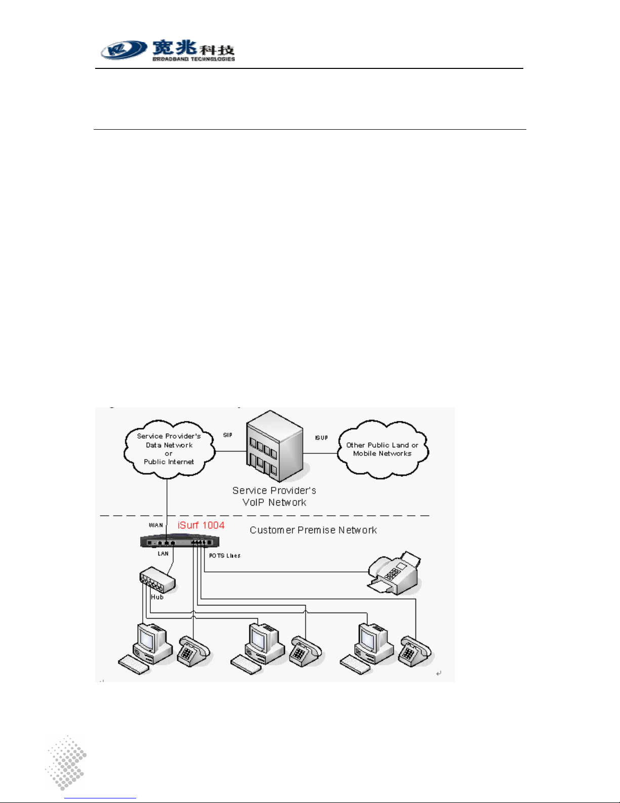
Figure 1 iSurf as a Gateway for Customer Premise Network..................................................... 1
Figure 2 Connections from iSurf to other Customer Premise Devices...................................... 7
Figure 3 SIP Capable Network Elements in a VoIP Network...................................................... 9
Figure 4 iSurf's Web Management Interface............................................................................ 10
Figure 5 Manage iSurf via Console.......................................................................................... 14
Figure 6 Define a Connection in HyperTerminal.......................................................................14
Figure 7 Select Communication Port in PC.............................................................................. 15
Figure 8 Setting Property of Communication Port in PC .......................................................... 15
Figure 9 Console Access to Management Interface................................................................. 16
Figure 10 Telnet Access into iSurf from LAN Segment............................................................... 17
Figure 11 Telnet into iSurf IAD from WAN Segment................................................................... 18
Figure 12 Logon Web Page .......................................................................................................19
Figure 13 iSurf's Web Management Interface............................................................................ 20
Figure 14 iSurf as a Gateway for Customer Premise Network................................................... 31
Figure 15 Transfer of T.30 Faxes in Transparent Mode.............................................................. 48
Figure 16 Transfer of T.30 Faxes using T.38 Fax Relay............................................................. 48
Figure 17 iSurf Application in a Private VoIP Network................................................................ 51
List of Tables
Table 1 Indicators on Top Panel................................................................................................ 2
Table 2 Interfaces in Real Panel................................................................................................ 3
Table 3 Packing list of an iSurf Package...................................................................................7
Table 4 Comparison of Management Methods ........................................................................ 13
Table 5 Alarms Defined in the iSurf System ............................................................................ 29
Table 6 Mapping of Configuration to SIP Messages................................................................ 40
iSurf 1004/1008 User Manuals
Page 1
1 Introduction
iSurf series of IAD (Integrated Access Device) products are designed for service providers that
offer both data and voice services over a high speed data access network.
iSurf helps service providers to rapidly reach out customer base. Newer generation of
telecommunication networks provide advanced services over a common infrastructure based on
IP (Internet protocol). However, a lot of legacy devices, e.g. analogue phones, and fax devices,
are not IP capable. iSurf is positioned for use in office or home environment, as a gateway for
legacy voice or fax devices to access services provided by advanced IP networks. With iSurf,
end users are not required to replace their legacy devices.
iSurf also helps service providers to better control data traffic at edge of their networks, so as to
ensure QoS (Quality of Services) for other users in the same network. iSurf series of products
are equipped with advance capability to differentiate end user traffic, marks traffic with different
priorities, and policing traffic at the edge of their networks. These capability are vital for service
providers to avoid service disruption caused by malicious users.
iSurf series of products provide multiple management interfaces to allow easy provision and
maintenance, e.g. console access, telnet, web based interfaces, and SNMP(Simple Network
Management Protocol) management interfaces for advanced network management systems.
Service providers are given a lot of flexibilities to provision and maintain the devices even after
they are rolled out into end user’s premises.
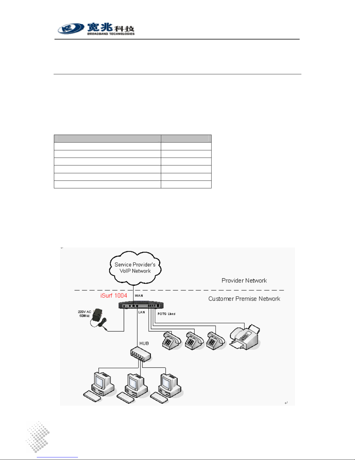
Figure 1 iSurf as a Gateway for Customer Premise Network
This manual provides reference information necessary for configuration and provisioning of iSurf
products. It can also be used by technical support engineers for troubleshooting and problem
resolution. A simplified manual for end-users can be provided upon request.
iSurf 1004/1008 User Manuals
Page 2
2 Product Specifications
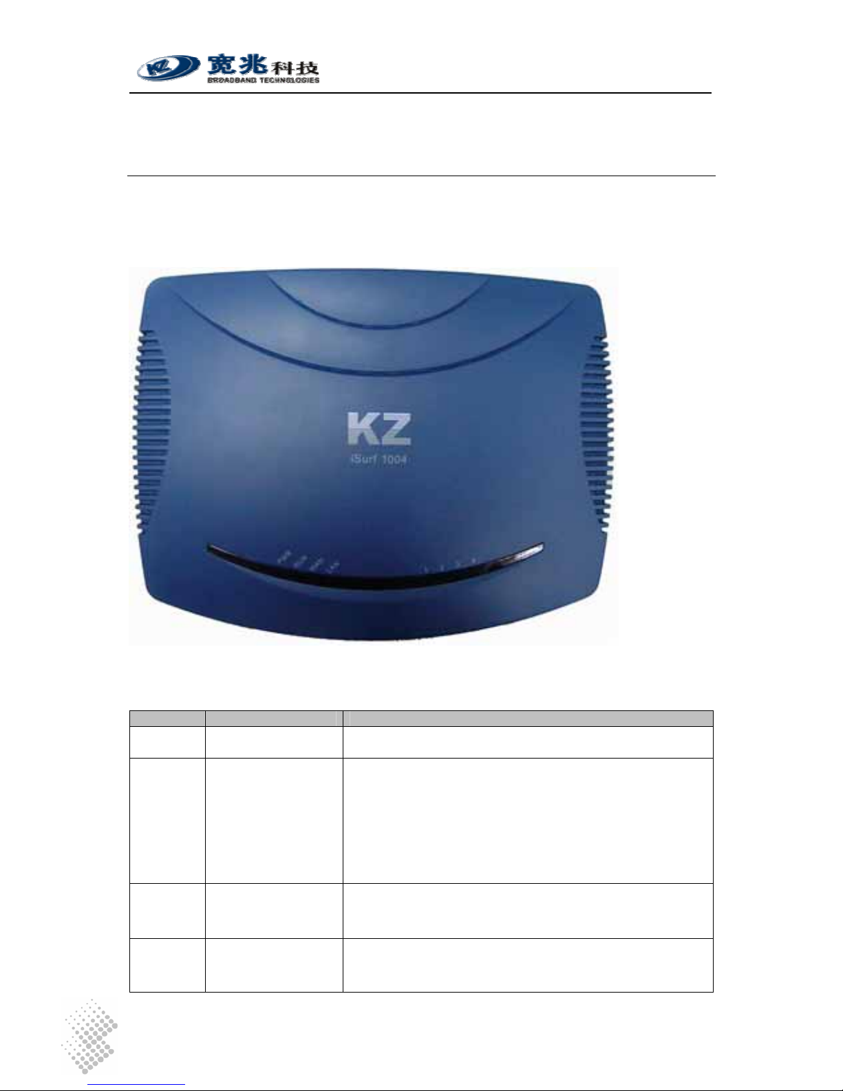
2.1 Product Layout
2.1.1 Top Panel
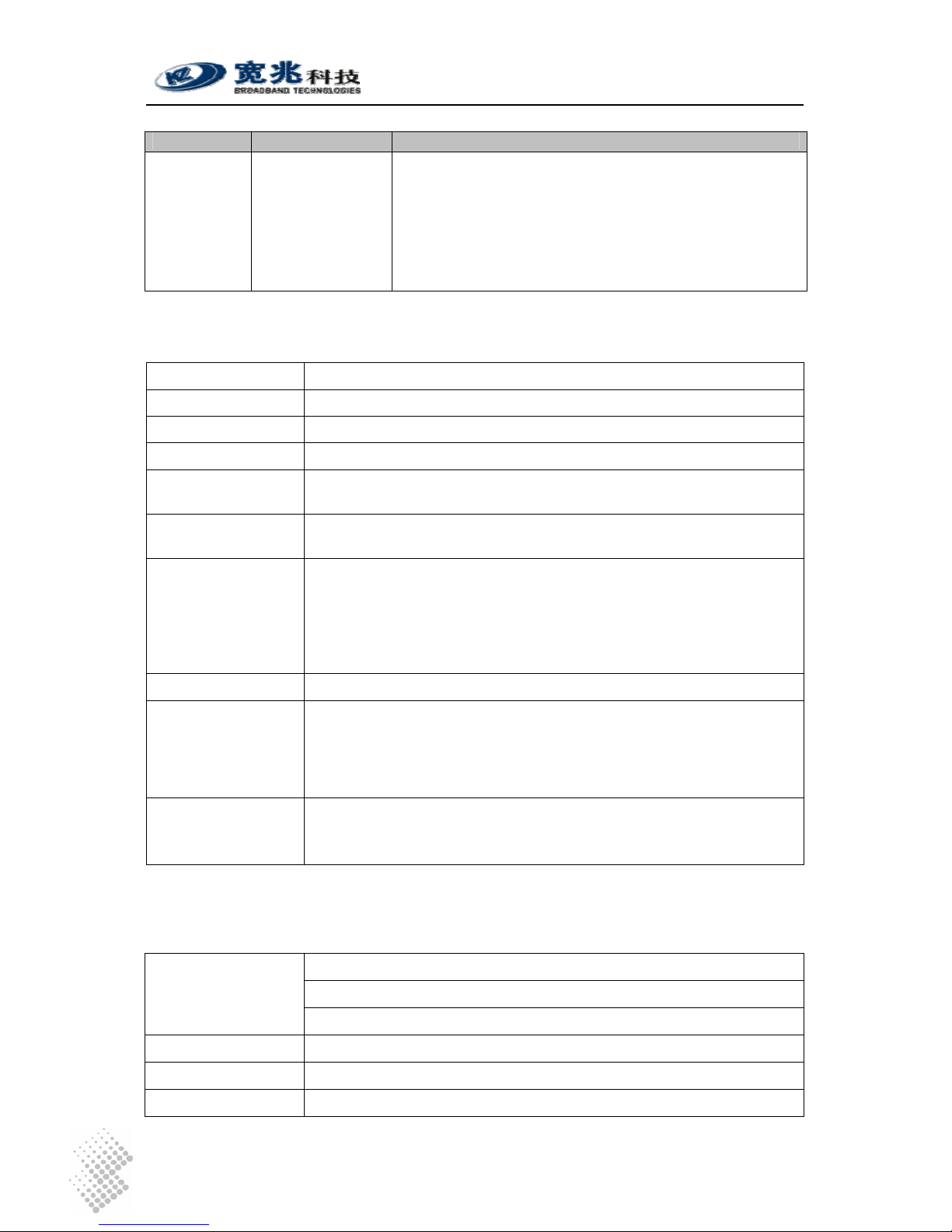
Table 1 Indicators on Top Panel
Indicator Description Function
PWR Power Status
Indicator
Stable light indicates system has been powered on.
RUN System Status
Indicator
Fast flash with 0.25 sec ON and 0.25 sec OFF indicates
the device is booting up system programs.
Unbalanced flash with 1.5 sec ON and 0.5 sec OFF
indicates device is restoring Factory Default Configuration.
Stable flash with 1 sec ON and 1 sec OFF indicates
system is running properly.
WAN
WAN Status
Indicator
Stable light indicates network connected properly.
Flashes indicates data transmit currently.
LAN
LAN Status Indicator Stable light indicates network connected properly.
Flash light indicates data transmit currently.
iSurf 1004/1008 User Manuals
Page 3
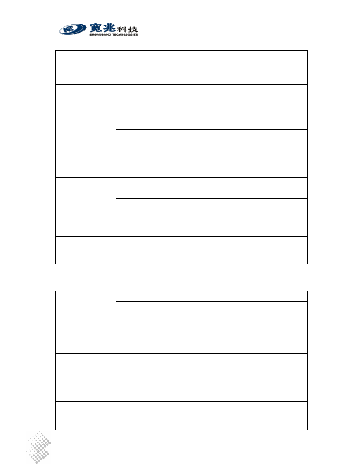
Indicator Description Function
1-8 Indicators for POTS
Interfaces to Analog
Phones or Fax
Stable Light indicates an POTS interface for phones or
faxes is not in use or faulty.
Stable OFF indicates a POTS interface is ready for use.
Flashing Light indicates a call is in progress via certain
POTS.
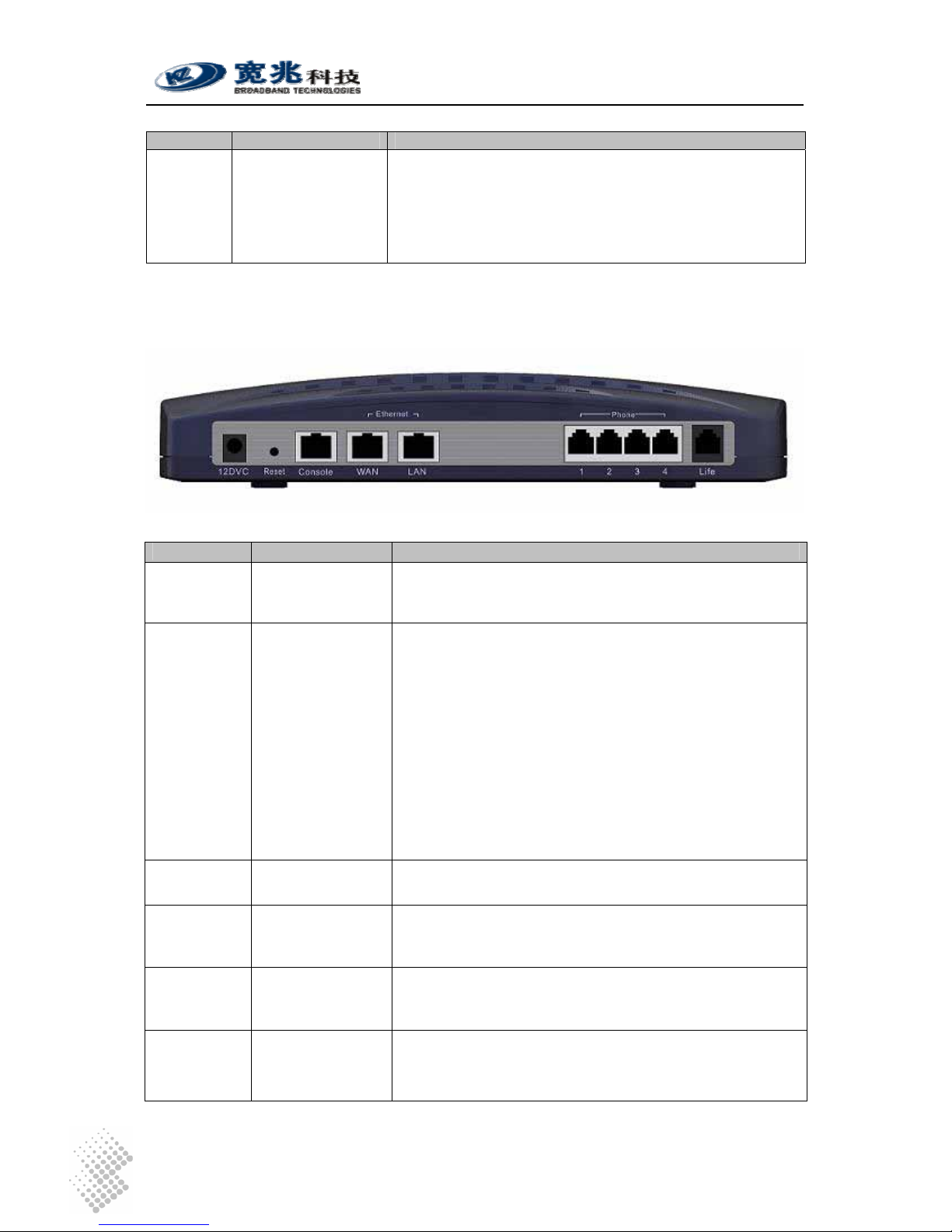
2.1.2 Rear Panel
Table 2 Interfaces in Real Panel
Interface Function Description
12DVC Power Input Jack Use 12V /1.5A DC Power adapter supplied with iSurf.
Misuse of power may cause damage to the device.
Reset Reset button,
which is sunk
slightly below
surface of rear
panel
To reset system configuration to factory default, turn off
power first. Press the Reset button and keep holding it
before turning on power again. When power supply is
turned on, the RUN indicator in the top panel will flash fast
initially, with 0.25 sec ON and 0.25 sec OFF, which
indicates the system is booting. Keep holding the Rest
button for about 1 minute until the RUN indicator start
flashing in a unbalanced pattern with light ON for 1.5 sec
and OFF for 0.5 sec, which indicates the system is
restoring factory default value. The Reset button may be
released then, however, the system may take 30 seconds
or longer to complete boot-up process.
Console Serial interface for
Console Access
Command Line user interface, offer Local Console
management.
WAN RJ45 Interface to
Wide Area
Network
Wide Area Network interface (RJ45), to connect
xDSL/Cable mode or Ethernet
LAN RJ45 Interface to
Local Area
Network
Local Area Network interface (RJ45), to connect to
computer, or a hub or switch.
Phones 1-8 RJ11 Interfaces to
Legacy Phones
and Fax
Depending on its model, an iSurf may provide different
number of RJ11 ports for legacy phones or fax machines.
iSurf 1004 provides 4 ports. iSurf 1008 provides 8 ports.
iSurf 1004/1008 User Manuals
Page 4
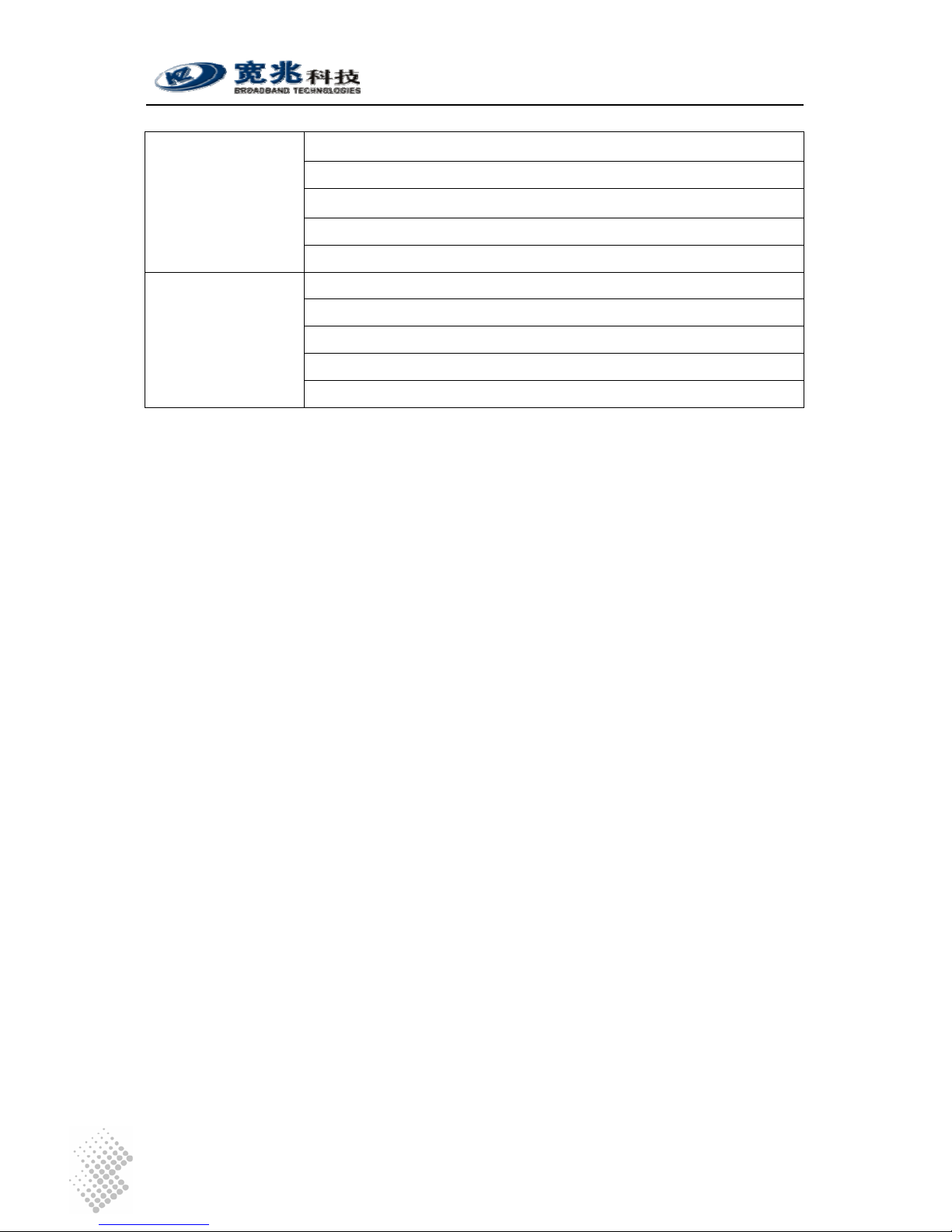
Interface Function Description
Life Line RJ11 interface to
PSTN
If a customer prefer, he may retain one analogue line
provided by PSTN service provider. This line can be
connected to the Life interface and is shared amongst all
phones and fax machines. When there is power outage,
outgoing calls from all local phones and fax machines will
be routed to this escape interface. However, only one local
phone can make call at one time.
2.2 Physical Specification
Dimensions 250mm (W) ×45mm (H) ×180mm (D)
Weight About 1 kg
Power Supply 12V DC
Power < 15W
Operating
Environment
Temperature 0 ~ 50 , ℃℃Relative humidity 10% ~ 90%, no-condensing
of humid is tolerated
Storage
Environment
Temperature -30 ~ ℃ 65 ,℃ Relative humidity 5% ~ 95%, no
condensing of humid is tolerated
Interface 1 10M/100M Ethernet port for WAN
1 10M/100M Ethernet port for LAN
4 (iSurf 1004) / 8 (iSurf 1008) POTS Interface
1 PSTN escape interface
1 Console Configuration Interface
1 12V DC Power Interface
Switch 1 Reset switch
Indicator Light PWR: Power Indicator
RUN: System Status Indicator
WAN: Wide Area Network Status Indicator
LAN: Local Area Network Status Indicator
POTS: 4 (iSurf 1004) / 8 (iSurf 1008) POTS Interface Status Indicator
Reliability System Available Time> 99.99%
MTBF > 100 K hours
Fault Recovery Interval < 2 min
2.3 Data Network Features
IEEE802.3 10Base Ethernet
IEEE802.3u 100Base Ethernet (Fast Ethernet)
Supported Protocol
IEEE802.3x Full / half duplex flow control
Duplex Auto Sensing
MAC Address 1 MAC address assigned by the vendor
MTU 1528 Bytes
iSurf 1004/1008 User Manuals
Page 5
1 IP address is required for WAN interface. The IP address for WAN
interface is typically allocated by the service provider by DHCP or
PPPoE.
IP Address
The default IP address for the LAN interface is 192.168.0.1.
IP Address
Acquisition
Support static IP address, DHCP and PPPoE
Data Switching
Mode
Store and Forward
148810pps with no packet inspection for QoS Throughput
600pps with packet inspection and tagging for QoS
Routing Protocol Static Route
Classification of internal traffic to SIGNALING and VOICE Traffic Classification
Classification of external traffic from LAN port to SIGNALING, VOICE,
and DATA based on deep packet inspection and stateful traffic learning
VLAN Tagging 802.1Q VLAN Tagging based on traffic classes
Marking of 802.1p bits based traffic classification QoS Marking
Marking of IPV4 DSCP field. based on traffic classification
QoS Scheduling Internal VOICE and SIGNALING is always prioritized against external
traffic.
Rate Limiting Rate Limiting on Ingress interfaces, configuration at 64K granularity
NTP Support NTP protocol and capable of acquiring timing from NTP
servers.
VPN Pass-through Support L2TP, PPP, IPSec pass-through
2.4 Voice Features
SIP Session Initiation Protocol
RTP Real Time Transfer Protocol
Supported Protocol
RTCP Real Time Transfer Control Protocol
Voice Encoder G.711,G.723,G.726,G.729
Noise Control Comfort Noise Generation & level control
Echo suppressing G.165/G.168-2000 echo suppress
Silence process Silence detection and suppressing
FAX T.30, T38
Delay and Packet
lose Process
Delay and jitter control/ Packet lose equalization
POTS Interface > 5km
Convergence Rate 1:01
Supported Service
PSTN Basic Service、PSTN supplementary service and value added
service
iSurf 1004/1008 User Manuals
Page 6
Under good network condition PSQM mean value <1.5;
Under bad network condition (PLR=1%,Jitter=20ms,
Delay=100ms) PSQM mean value<1.8;
Under worst condition (PLR=5%,Jitter=60ms,Delay=400ms)
Voice Quality
Perceptual Speech
Quality
Measurements
PSQM mean value <2.0
Under good network condition MOS>4.0;
Under fair network condition (PLR=1%,Jitter=20ms,
Delay=100ms) MOS>3.5;
Under worst condition (PLR=5%,Jitter=60ms,Delay=400ms)
Voice Quality Mean
Opinion Score
MOS>3.0
2.5 Management Features
iSurf supports the following configuration and management methods
• Local Console Management
• Remote Telnet Management
• Web based Management Interface
• SNMP Interfaces to Advanced Network Management Systems
iSurf 1004/1008 User Manuals
Page 7
3 Getting Started
3.1 Packing list
Unpack iSurf product package carefully. Every iSurf product package comes with the following
items:
Table 3 Packing list of an iSurf Package
Description Quantity
iSurf IAD 1
12V DC Power Adapter 1
Ethernet Cable 1
RS232 Serial Console Cable 1
User Menu 1
Product Warranty Card 1
If you find any of the items is missing, please contact our local distributor immediately.
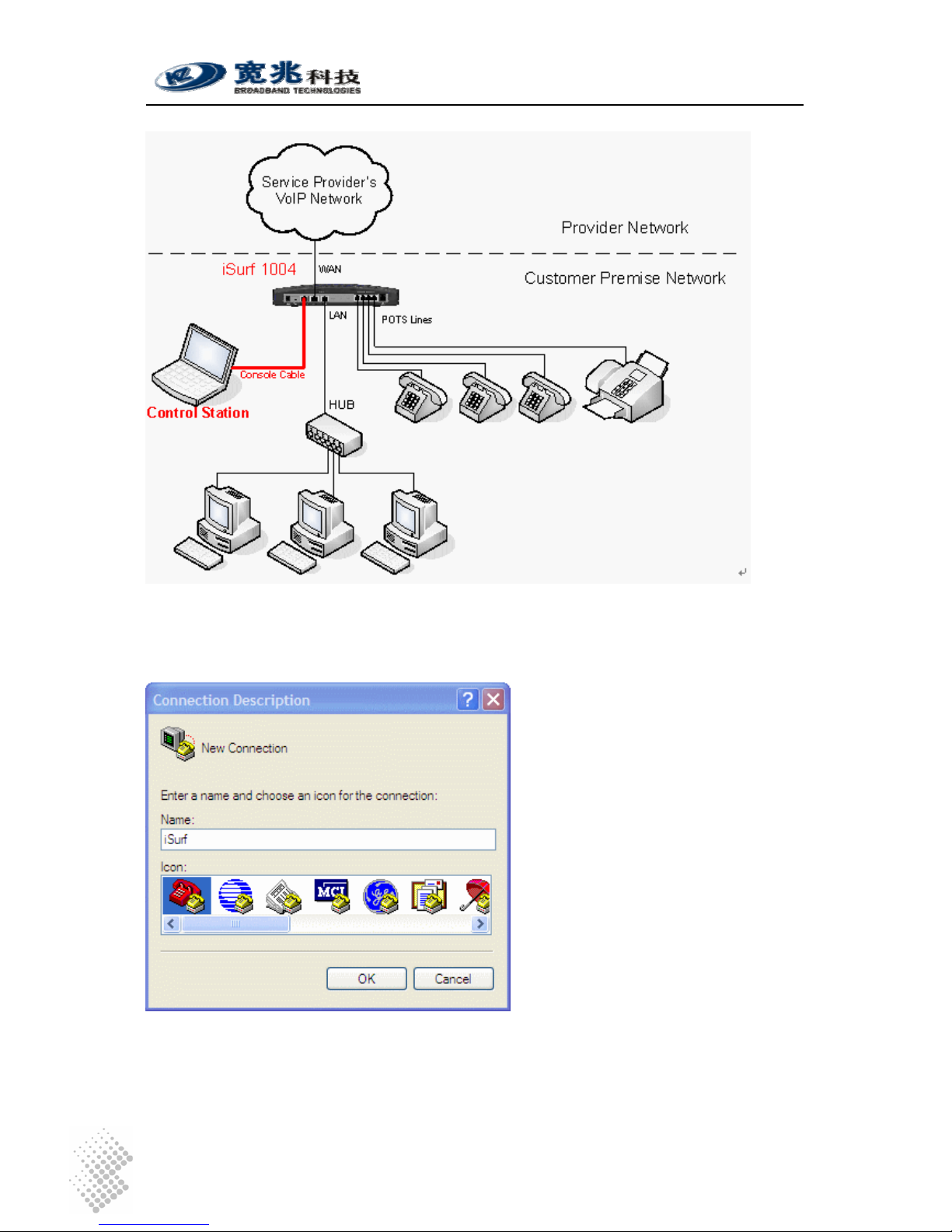
3.2 Connecting other Customer Premise Devices
It is recommended that iSurf are installed in a clean, dry and ventilated indoor environment. Keep
the device far from other heat sources and do not block ventilation slots at both side of the device.
Figure 2 Connections from iSurf to other Customer Premise Devices

iSurf 1004/1008 User Manuals
Page 8
Figure 2 illustrates connections from iSurf 1004 to other devices in a customer premise network.
1. POTS lines: Connect phones and fax machines to one of the RJ-11 jacks in rear panel.
2. WAN: Connect an Ethernet cable from xDSL/Cable modem to the RJ45 jack for WAN
(Wide Area Network) in rear panel
3. LAN: Connect an Ethernet cable from your computer ’s network adapter to the RJ45 jack
for LAN (Local Area Network) in real panel. An Ethernet switch or hub can also be used
to provide more Ethernet ports for more computers.
4. Power: After connect to power source, iSurf will start up automatically. It may take 30
seconds or longer for iSurf to fully complete the boot-up process.
In Figure 2 all four FXS ports of an iSurf 1004 have been fully utilized. If there are still idle ports
available, it is recommended, but not necessary, to power off iSurf before connecting new
devices.
3.3 Example Configuration
This section shows a quick example on how iSurf works with an service provider’s offering voice
services based on SIP (Session Negotiation Protocol).
Caution Configuration data discussed in this section is for illustration
purpose only. Actual configuration may differ depending on your
service provider network scenario.
SIP is an application layer signaling-control protocol used to establish, maintain, and terminate
multimedia sessions. Multimedia sessions include internet telephony, conference, and other
similar applications involving such media as audio, video, and data.
iSurf may initiates SIP call requests to other SIP capable node. If an calling party knows IP
address of the called party, the calling party may initiate a call request directly to the called party.
However, in a large network, such intelligence is difficult to maintain by end points. Service
providers’ infrastructure plays an vital role in facilitating telecommunications communication.
A large scale telecommunication network typically consists of the following components:
SIP Clients: SIP Clients, also widely referred as User Agents, typically represent
subscriber devices that are capable of initiating and accepting SIP calls. A SIP
client is identified by its SIP address, e.g. bob@myserviceprovider.com. The
format of SIP addresses is very similar to an email address. In many
networks, it may also appear as <Dial Number>@myserviceprovider.com.
Dial Number is a string of numeric digits. SIP Addresses and Dial Numbers
should be provided by Service Provider before commissioning an iSurf.
Registrar: Registrar authenticate SIP Clients and maintain their status. Each SIP Client
is required to register itself to Registrar periodically and announce its latest IP
address. In this way IP addresses of all SIP clients in the network are updated,
Proxy may look up IP address of a called party using Dial Number or SIP
address. The IP address or host name of Registrar should be provided by
Service Provider to configure an iSurf. In certain networks, Proxy may forward
registration messages to Registrar, as such IP address of Registrar can be
specified the same as the IP address of Proxy.
Proxy Proxy performs network address translation, and assists in locating called

iSurf 1004/1008 User Manuals
Page 9
party. Proxy may also inter-work with other service providers’ networks if the
called party is outside boundary of the network, while a end user may not
have the permission to do so. The IP address or hostname of the Proxy
should be provided by Service Provider.
Figure 3 SIP Capable Network Elements in a VoIP Network
3.3.1 Establish Network Connectivity
Connect WAN port of iSurf to an Ethernet port provided by service provider, e.g. a port in Cable
Modem or DSL Modem. Assuming the network do not require any authentication to issue an IP
address, iSurf will acquire an IP address for its WAN interface through DHCP.
Default IP address of iSurf’s LAN interface is 192.168.0.1. By default iSurf also serves as an
DHCP server for the LAN segment. It allocates addresses in 192.168.0.2-244 range to
requesting IP address by DHCP. NAT is enabled between the LAN segment and the WAN
segment.
Change TCP/IP settings of your PC to DHCP mode. Connect your PC to LAN interface of the
iSurf IAD, make sure your PC acquires an IP address. You should be able to PING the IP
address LAN interface of iSurf IAD 192.168.0.1, otherwise please follow guidelines in Section 4.1
to troubleshoot. Launch web browser to visit http://192.168.0.1
. A small window will pop up and
ask for user name and password. Fill in the default user name and password.
Username: admin
Password: admin
iSurf 1004/1008 User Manuals
Page 10
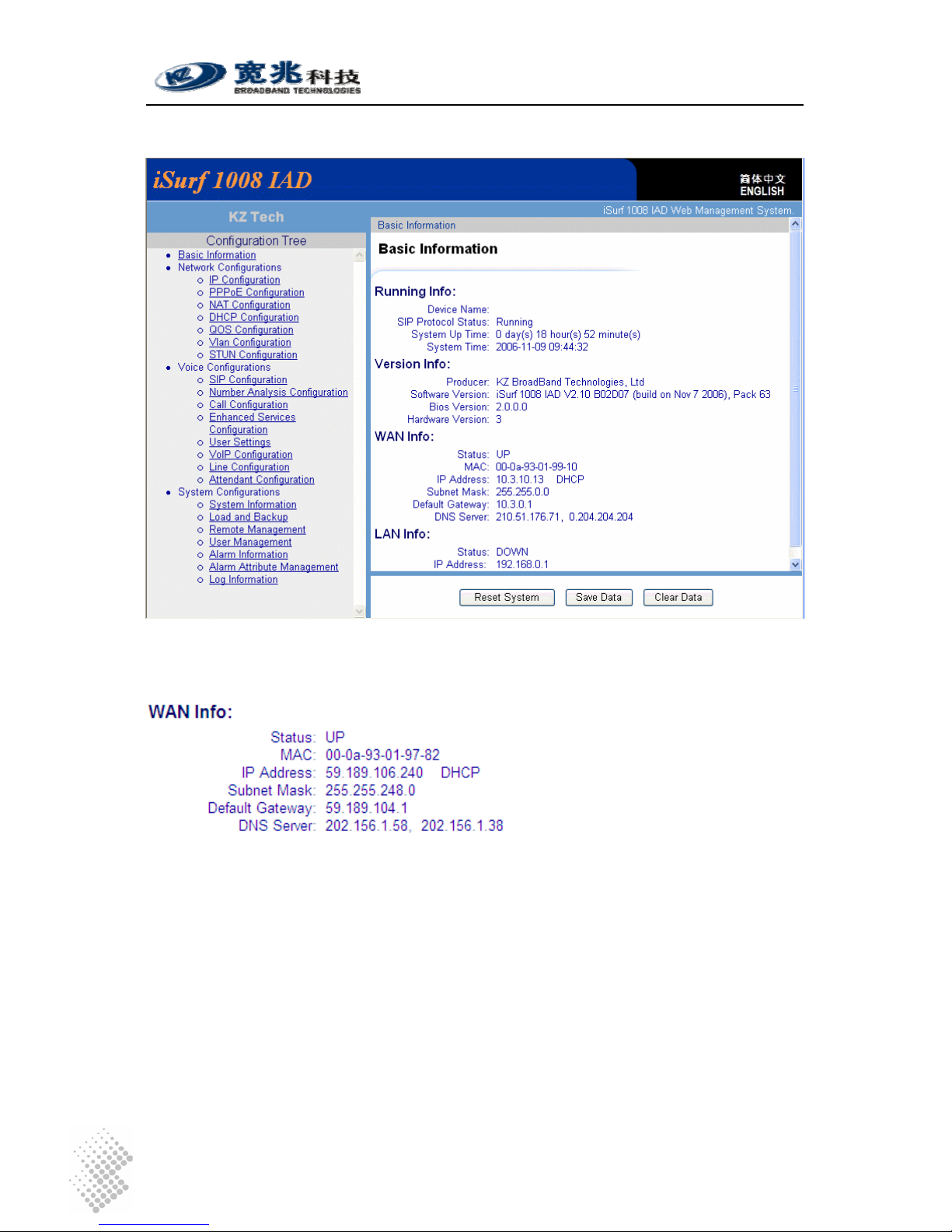
You will be brought into the web administration interface provided by the iSurf IAD.
Figure 4 iSurf's Web Management Interface
Verify that WAN interface is up, otherwise follow guidelines in later sections to trouble shoot.
3.3.2 Example SIP Configuration
The example configuration assumes the following concerning the service provider.
Registrar’s IP Address Not used. Proxy server forwards relevant SIP
messages to Registrar.
Proxy’s IP address 202.156.1.248
Dial Number of the analogue phone 85412006
SIP Address for analogue Phone 85412006@myisp.net
Password for the above SIP address: pass2006
Each iSurf 1004 unit provides four interfaces for POTS devices. The following configuration
assumes an analogue phone is connected to FXS port 1.
iSurf 1004/1008 User Manuals
Page 11
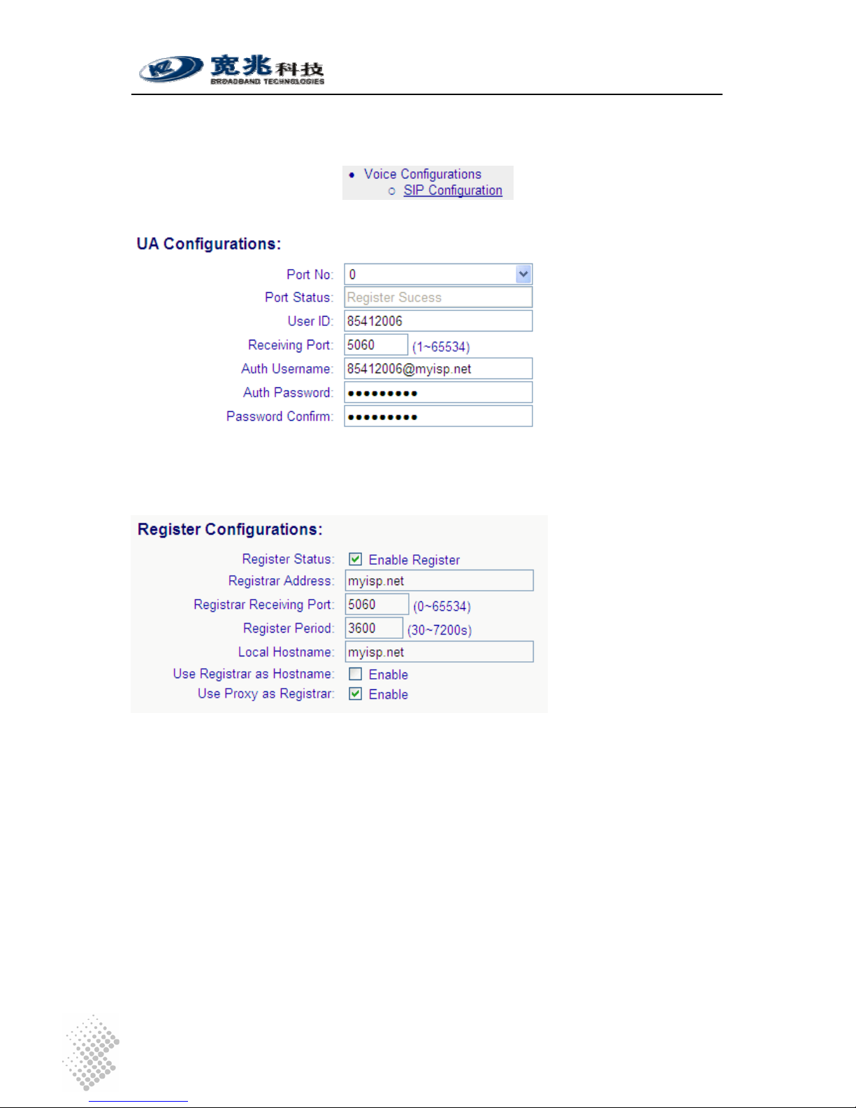
Click on “SIP Configurations” in the left area of the browser window:
Fill in the following in “UA Configuration” section.
UA stands for User Agent. Internally FXS ports are counted from 0. Phone port 1 maps to Port No
0 internally. The “User ID” maps to dial number. Apply settings after changes are made.
Next comes to Registrar configurations.
When “Enable Register” is enabled, registration message will be sent out. However when “Use
Proxy as Registrar” is enabled, registration messages are sent to the IP address of Proxy.
When “Enable Register” is disabled, iSurf may be configured for point to point communications,
which is typically used by multi-site enterprises. Apply settings after changes are made.
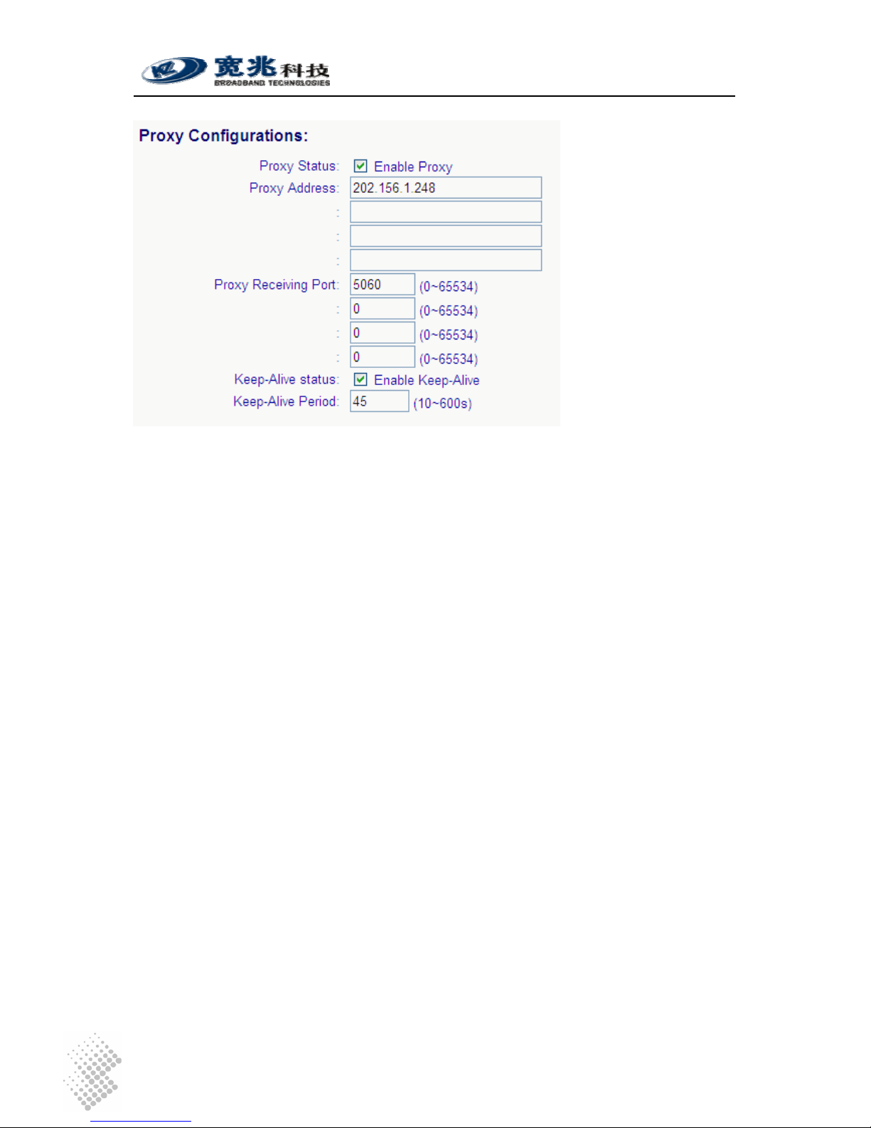
Next comes to SIP Configurations.
iSurf 1004/1008 User Manuals
Page 12
If more than one Proxy Address are supplied, an iSurf IAD will try each Proxy sequentially if a
request times out. Apply settings after changes are made.
After complete all settings, you may uncheck “Enable Register” and apply settings to de-register
the iSurf. Check “Enable Register” and Apply settings again to perform a new registration. If an
registration is successful, the “Port Status” under “UA Configurations” should show “Register
Success”.
Configure another iSurf in a similar way. The only difference is the Dial Number and SIP Address.
Dial Number of the analogue phone 85412010
SIP Address for analogue phone 85412010@myisp.net
If both iSurf register successfully, make a call from the phone 85412006 to another phone
85412010 by dialing 85412010 at the phone pad.
Save configuration data by pressing [Save Data] button.
iSurf 1004/1008 User Manuals
Page 13
4 Managing iSurf
iSurf supports four management methods: CONSOLE, TELNET, WEB base and SNMP
management, from local or from remote central offices.
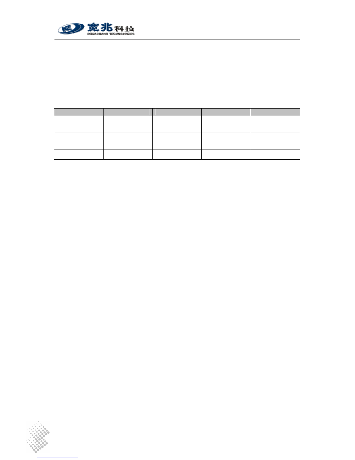
Table 4 Comparison of Management Methods
Console Telnet Web SNMP
User Interface Command Line Command Line Graphic User
Interface
Graphic User
Interface
Management
Distance
Local Local or Remote Local or Remote Local or Remote
User credentials Not encrypted Not encrypted Encrypted Not encrypted
User name and password are required for access to management functions. There are two levels
or privileges: administrators’ privilege and normal users’ privileges.
• Administrator’s privilege is designed for service providers to provision an iSurf IAD,
before selling or leasing out iSurf to end users. By supplying administrator’s user name
and password, a technician has access to all configurations of an iSurf IAD. Default user
name for administrator’s privileges is “admin”. Default password is “admin”.
• Users’ privilege is provisioned for end users to make limited changes of configurations for
an iSurf IAD, Most of other configuration are not visible to when accessed with normal
user’s privileges. Default user name for administrator’s privileges is: user. Default
password is “user”.
4.1 Managing iSurf via Console
iSurf can be managed via console port. Any PC with a serial communication port and installed
with Terminal emulation application, e.g. HyperTerminal software as part of Windows operating
system, can be used as an console to manage iSurf IAD.
Connect your PC’s COM port (DB9) to the Console port (RJ45) using the special console cable
provided with iSurf.
iSurf 1004/1008 User Manuals
Page 14
Figure 5 Manage iSurf via Console
Select Start – Programs – Accessories – Communication- Hyper Terminal from your PC. You will
be prompted to provide a name for the new connection. Type in “iSurf” in the name field.
Figure 6 Define a Connection in HyperTerminal
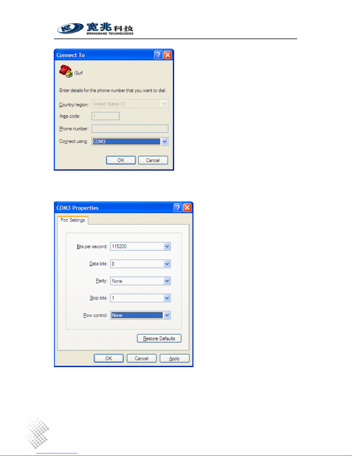
Click on the drop down list right to “Connecting using:”, and select the right port that is connected
to the console port of iSurf. In the example below, COM3 port is used.
iSurf 1004/1008 User Manuals
Page 15
Figure 7 Select Communication Port in PC
Press “OK” button, a new window titled “COM3 Properties” will pop up:
Figure 8 Setting Property of Communication Port in PC
Set the following parameters for the COM port:
Bits per second: 115200
Data bits: 8
 Loading...