


iSurfTM 1004/1008
Integrated Access Device
User Manual
KZ BROADBAND TECHNOLOGIES, LTD. C
ONFIDENTIAL
This document and the information contained in it is confidential information of KZ Broadband Technologies
Ltd (KZTech), and shall not be used, or publish, or disclosed, or disseminated outside of KZTech in whole or
in part without KZTech’s consent. This document contains trade secrets of KZTech. Reverse engineering of
any or all of the information in document is prohibited. The copyright notice does not imply publication of
this document.
© C
OPYRIGHT 2006, KZ Broadband Technologies, Ltd.
CONFIDENTIAL INFORMATION
Information contained herein is proprietary to KZTech for whose benefit
confidentiality shall be maintained.
iSurf 1004/1008 User Manuals
Page II
Revision History
Version Date Author Description
1.0 June 20,2006 KZ Broadband Technologies Initial Release
1.1 Nov. 8, 2006 KZ Broadband Technologies Removal of Encryption Feature

iSurf 1004/1008 User Manuals
Page III
Table of Contents
1 INTRODUCTION....................................................................................................................1
2 PRODUCT SPECIFICATIONS............................................................................................... 2
2.1 P
RODUCT LAYOUT ............................................................................................................ 2
2.1.1 Top Panel.................................................................................................................... 2
2.1.2 Rear Panel .................................................................................................................. 3
2.2 P
HYSICAL SPECIFICATION.................................................................................................. 4
2.3 D
ATA NETWORK FEATURES................................................................................................ 4
2.4 V
OICE FEATURES.............................................................................................................. 5
2.5 M
ANAGEMENT FEATURES.................................................................................................. 6
3 GETTING STARTED ............................................................................................................. 7
3.1 P
ACKING LIST.................................................................................................................... 7
3.2 CONNECTING OTHER CUSTOMER PREMISE DEVICES........................................................... 7
3.3 E
XAMPLE CONFIGURATION ................................................................................................ 8
3.3.1 Establish Network Connectivity................................................................................... 9
3.3.2 Example SIP Configuration ....................................................................................... 10
4 MANAGING ISURF............................................................................................................. 13
4.1 M
ANAGING ISURF VIA CONSOLE....................................................................................... 13
4.2 MANAGING ISURF BY TELNET ACCESS.............................................................................. 16
4.2.1 Telnet Access to iSurf from LAN Segment.................................................................17
4.2.2 T elnet Access from WAN Segment............................................................................17
4.3 M
ANAGING ISURF IAD FROM A WEB BROWER................................................................... 18
4.3.1 Access iSurf’s from LAN Segment ............................................................................ 18
4.3.2 Access iSurf’s from WAN Segment........................................................................... 19
4.4 SNMP
METHOD.............................................................................................................. 19
5 SYSTEM CONFIGURATIONS VIA WEB INTERFACE........................................................ 20
5.1 W
ELCOMING PAGE.......................................................................................................... 20
5.1.1 Configuration Tree..................................................................................................... 20
5.1.2 Detailed Configuration Window................................................................................. 21
5.1.3 Reset System, Save Data and Clear Data................................................................ 21
5.2 S
YSTEM INFORMATION .................................................................................................... 21
5.2.1 Basic System Information.......................................................................................... 21
5.2.2 System Time ............................................................................................................. 22
5.2.3 Contact Info Configuration......................................................................................... 22
5.3 L
OAD AND BACKUP.......................................................................................................... 23
5.3.1 Load or Backup over TFTP ....................................................................................... 23
5.3.2 Load or Backup over HTTP....................................................................................... 24
5.4 U
SER MANAGEMENT....................................................................................................... 26
5.4.1 Display Existing Users............................................................................................... 26
5.4.2 Add Delete and Modify User ..................................................................................... 26
5.4.3 ACL(Access Control List) Management .................................................................... 27
5.5 A
LARMS ......................................................................................................................... 28
5.5.1 Current Alarm............................................................................................................ 28
5.5.2 History Alarm............................................................................................................. 28
5.6 A
LARM ATTRIBUTE MANAGEMENT .................................................................................... 29

iSurf 1004/1008 User Manuals
Page IV
5.6.1 Defined Alarms.......................................................................................................... 29
5.7 S
YSTEM LOG .................................................................................................................. 30
6 NETWORK CONFIGURATIONS VIA WEB INTERFACES ................................................. 31
6.1 IP
CONFIGURATION......................................................................................................... 31
6.1.1 IP Address Configuration........................................................................................... 32
6.1.2 Static Route Configuration......................................................................................... 32
6.1.3 ARP table and Configuration..................................................................................... 32
6.2 PPP
OE CONFIGURATION................................................................................................. 33
6.3 NAT
CONFIGURATION...................................................................................................... 33
6.4 DHCP
SERVER CONFIGURATION ..................................................................................... 34
6.5 QOS MARKING AND VLAN CONFIGURATION..................................................................... 35
6.5.1 VLAN Configuration................................................................................................... 35
6.5.2 QoS Configuration..................................................................................................... 35
6.5.3 Classification of Ingress T raf fic.................................................................................. 36
6.6 STUN
CONFIGURATION................................................................................................... 38
7 VOICE CONFIGURATIONS................................................................................................. 39
7.1 SIP
CONFIGURATION....................................................................................................... 39
7.1.1 User Agent Configuration .......................................................................................... 39
7.1.2 Proxy Configuration................................................................................................... 40
7.1.3 Mapping of SIP Configuration to SIP Messages........................................................ 40
7.2 N
UMBER ANALYSIS CONFIGURATION ................................................................................ 41
7.2.1 Conditions to Modified Dial Numbers........................................................................ 41
7.2.2 Number Change Configurations................................................................................ 42
7.3 C
ALL CONFIGURATION..................................................................................................... 42
7.3.1 Dial Plan Configuration.............................................................................................. 43
7.3.2 Multiple Lines using a Single Account....................................................................... 43
7.3.3 Call Timers................................................................................................................ 44
7.4 E
NHANCED SERVICES CONFIGURATION............................................................................ 44
7.5 U
SER SETTINGS ............................................................................................................. 45
7.6 V
OIP CONFIGURATION .................................................................................................... 46
7.6.1 Codec Configurations................................................................................................ 46
7.6.2 Media Protocol .......................................................................................................... 49
7.7 L
INE CONFIGURATION...................................................................................................... 49
7.7.1 Port Attribute ............................................................................................................. 50
7.7.2 Port Fax Attribute....................................................................................................... 50
7.7.3 Private Number ......................................................................................................... 50
7.7.4 Line Maintenance...................................................................................................... 51
7.8 A
TTENDANT CONFIGURATION........................................................................................... 52
8 COMMAND LINE INTERFACE ........................................................................................... 53
8.1 C
OMMAND MODES.......................................................................................................... 54
8.1.1 Returning to Parental Level....................................................................................... 55
8.2 A
LL COMMANDS.............................................................................................................. 55

iSurf 1004/1008 User Manuals
Page V
List of Figures
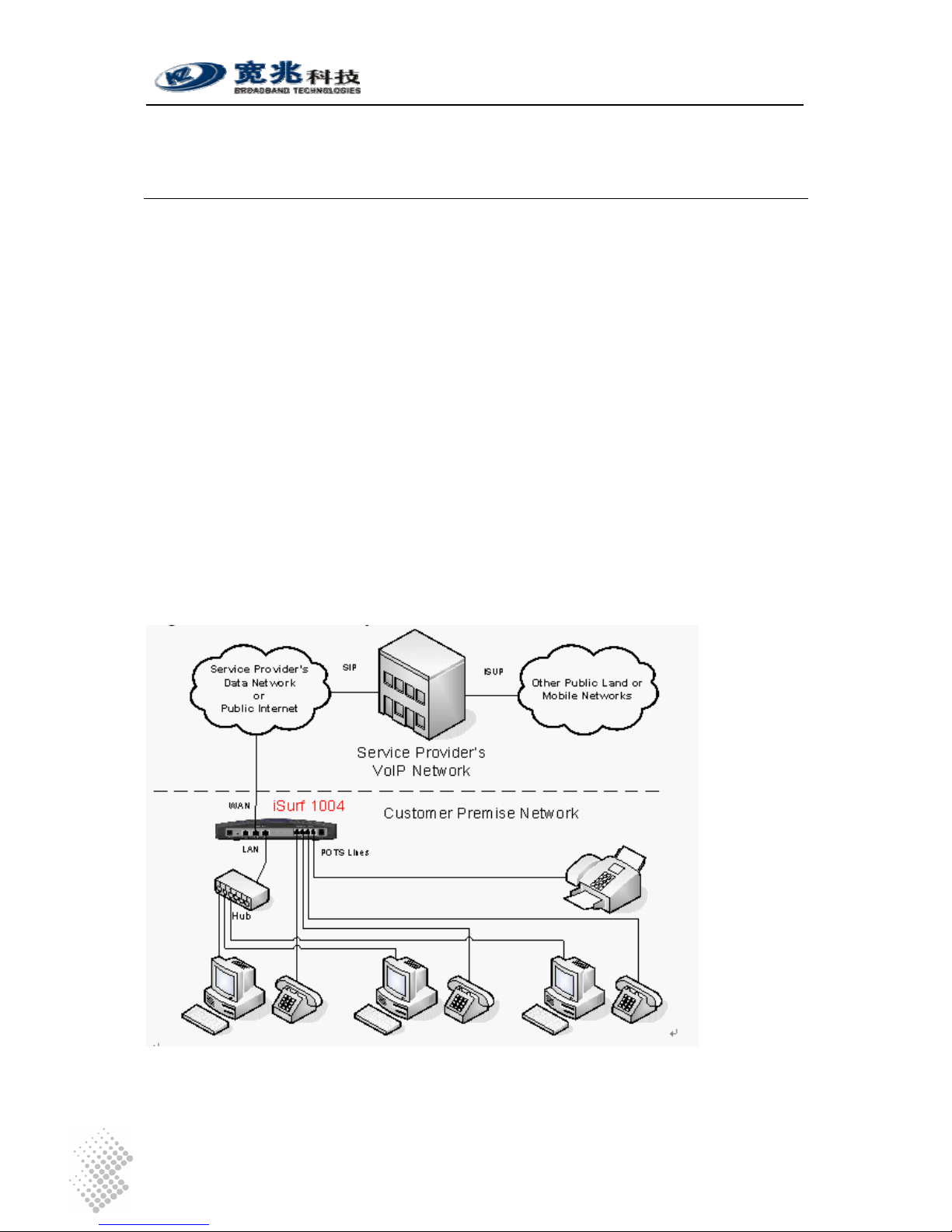
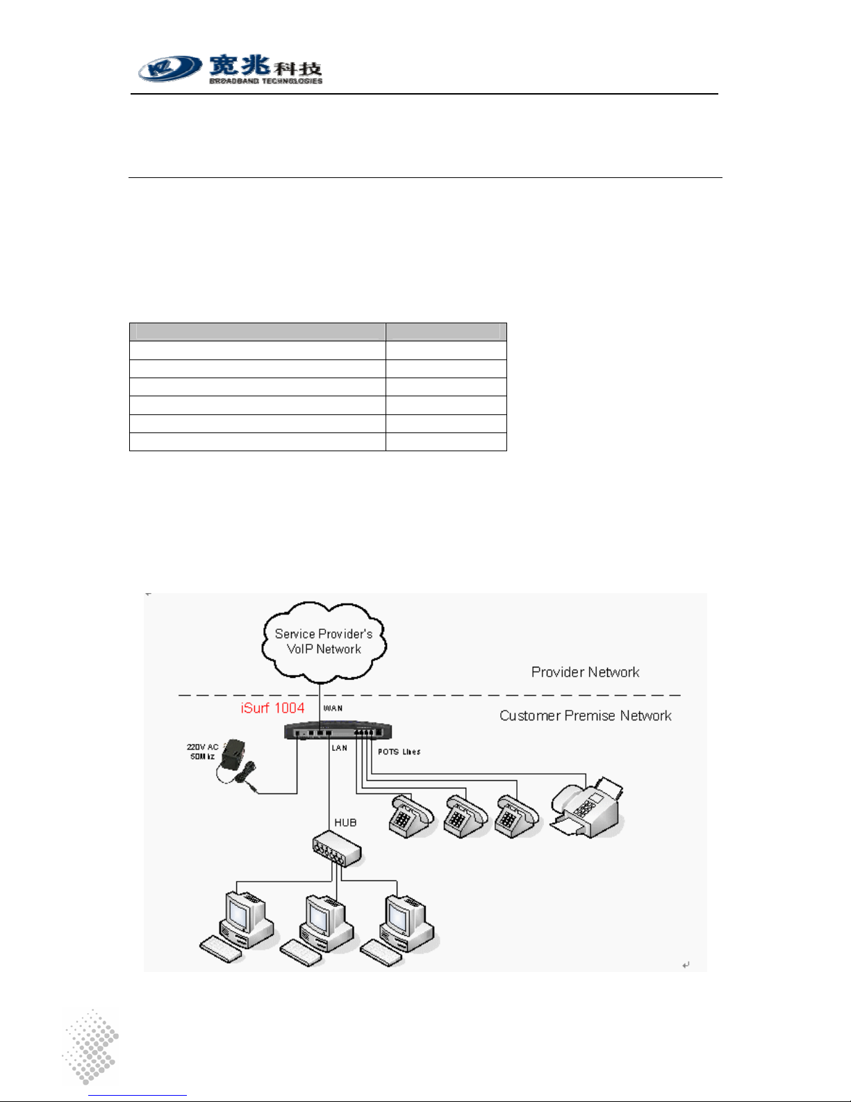
Figure 1 iSurf as a Gateway for Customer Premise Network..................................................... 1
Figure 2 Connections from iSurf to other Customer Premise Devices...................................... 7
Figure 3 SIP Capable Network Elements in a VoIP Network...................................................... 9
Figure 4 iSurf's Web Management Interface............................................................................ 10
Figure 5 Manage iSurf via Console.......................................................................................... 14
Figure 6 Define a Connection in HyperTerminal.......................................................................14
Figure 7 Select Communication Port in PC.............................................................................. 15
Figure 8 Setting Property of Communication Port in PC .......................................................... 15
Figure 9 Console Access to Management Interface................................................................. 16
Figure 10 Telnet Access into iSurf from LAN Segment............................................................... 17
Figure 11 Telnet into iSurf IAD from WAN Segment................................................................... 18
Figure 12 Logon Web Page .......................................................................................................19
Figure 13 iSurf's Web Management Interface............................................................................ 20
Figure 14 iSurf as a Gateway for Customer Premise Network................................................... 31
Figure 15 Transfer of T.30 Faxes in Transparent Mode.............................................................. 48
Figure 16 Transfer of T.30 Faxes using T.38 Fax Relay............................................................. 48
Figure 17 iSurf Application in a Private VoIP Network................................................................ 51
List of Tables
Table 1 Indicators on Top Panel................................................................................................ 2
Table 2 Interfaces in Real Panel................................................................................................ 3
Table 3 Packing list of an iSurf Package...................................................................................7
Table 4 Comparison of Management Methods ........................................................................ 13
Table 5 Alarms Defined in the iSurf System ............................................................................ 29
Table 6 Mapping of Configuration to SIP Messages................................................................ 40
iSurf 1004/1008 User Manuals
Page 1
1 Introduction
iSurf series of IAD (Integrated Access Device) products are designed for service providers that
offer both data and voice services over a high speed data access network.
iSurf helps service providers to rapidly reach out customer base. Newer generation of
telecommunication networks provide advanced services over a common infrastructure based on
IP (Internet protocol). However, a lot of legacy devices, e.g. analogue phones, and fax devices,
are not IP capable. iSurf is positioned for use in office or home environment, as a gateway for
legacy voice or fax devices to access services provided by advanced IP networks. With iSurf,
end users are not required to replace their legacy devices.
iSurf also helps service providers to better control data traffic at edge of their networks, so as to
ensure QoS (Quality of Services) for other users in the same network. iSurf series of products
are equipped with advance capability to differentiate end user traffic, marks traffic with different
priorities, and policing traffic at the edge of their networks. These capability are vital for service
providers to avoid service disruption caused by malicious users.
iSurf series of products provide multiple management interfaces to allow easy provision and
maintenance, e.g. console access, telnet, web based interfaces, and SNMP(Simple Network
Management Protocol) management interfaces for advanced network management systems.
Service providers are given a lot of flexibilities to provision and maintain the devices even after
they are rolled out into end user’s premises.
Figure 1 iSurf as a Gateway for Customer Premise Network
This manual provides reference information necessary for configuration and provisioning of iSurf
products. It can also be used by technical support engineers for troubleshooting and problem
resolution. A simplified manual for end-users can be provided upon request.
iSurf 1004/1008 User Manuals
Page 2
2 Product Specifications
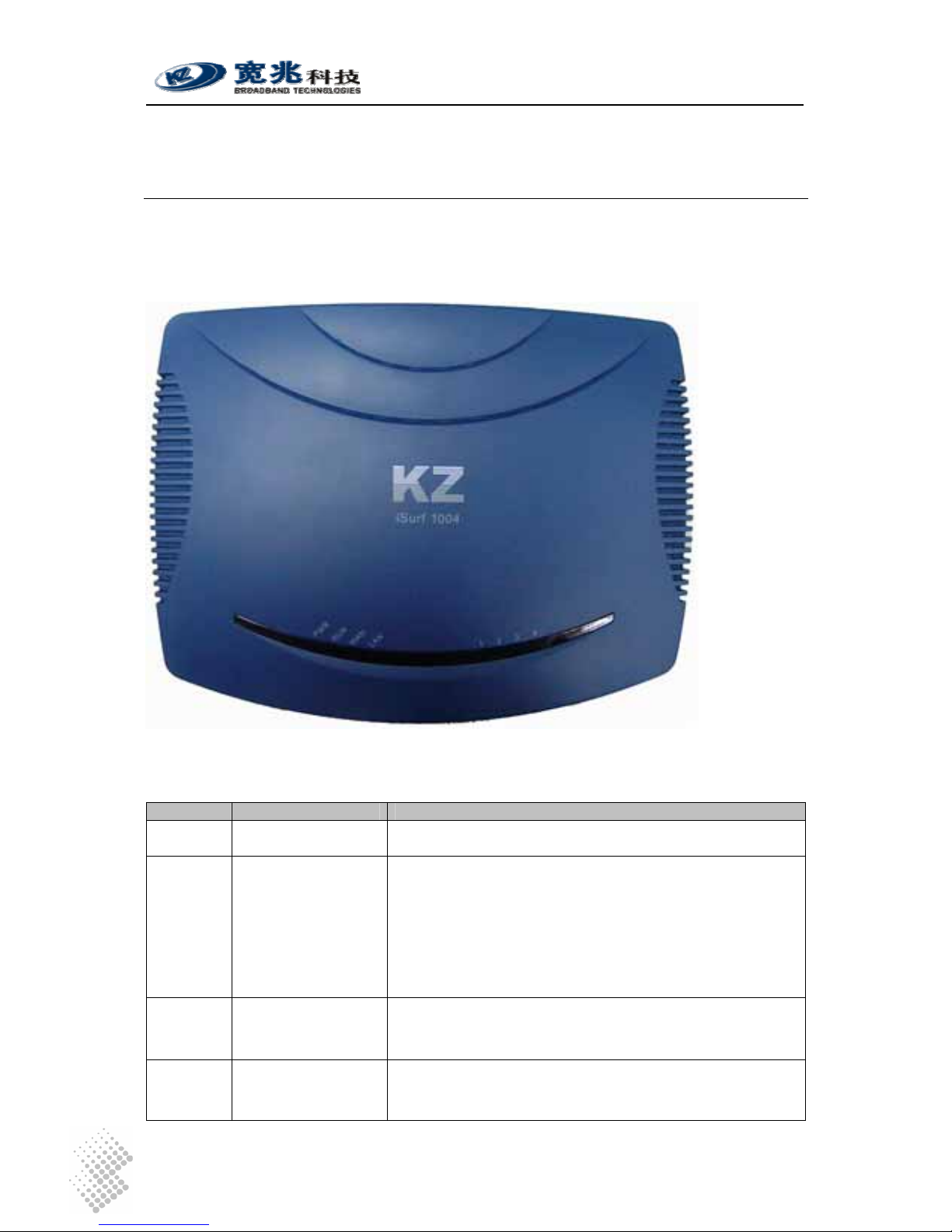
2.1 Product Layout
2.1.1 Top Panel
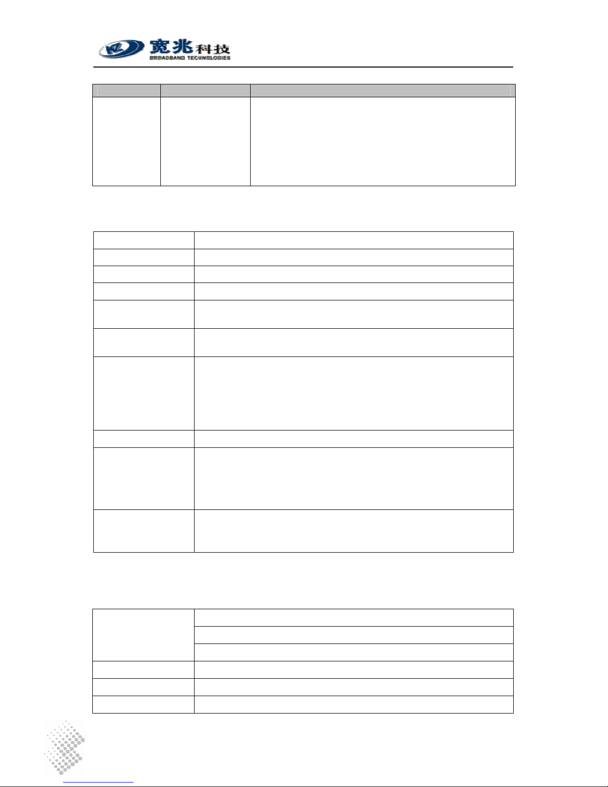
Table 1 Indicators on Top Panel
Indicator Description Function
PWR Power Status
Indicator
Stable light indicates system has been powered on.
RUN System Status
Indicator
Fast flash with 0.25 sec ON and 0.25 sec OFF indicates
the device is booting up system programs.
Unbalanced flash with 1.5 sec ON and 0.5 sec OFF
indicates device is restoring Factory Default Configuration.
Stable flash with 1 sec ON and 1 sec OFF indicates
system is running properly.
WAN
WAN Status
Indicator
Stable light indicates network connected properly.
Flashes indicates data transmit currently.
LAN
LAN Status Indicator Stable light indicates network connected properly.
Flash light indicates data transmit currently.
iSurf 1004/1008 User Manuals
Page 3
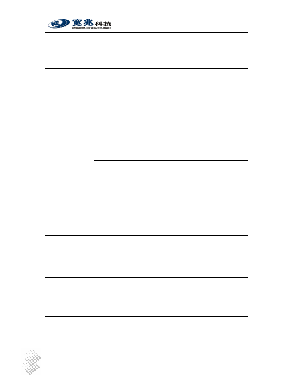
Indicator Description Function
1-8 Indicators for POTS
Interfaces to Analog
Phones or Fax
Stable Light indicates an POTS interface for phones or
faxes is not in use or faulty.
Stable OFF indicates a POTS interface is ready for use.
Flashing Light indicates a call is in progress via certain
POTS.
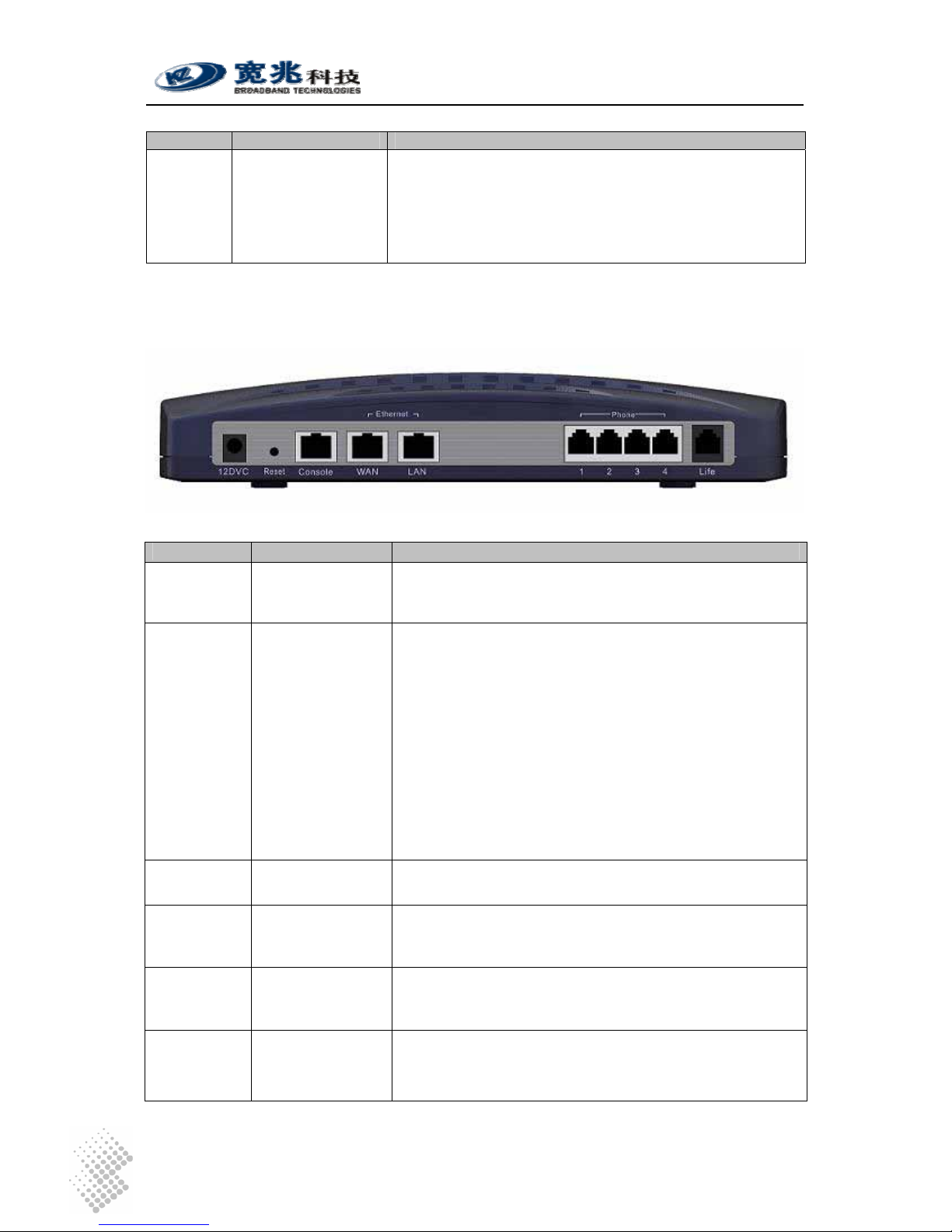
2.1.2 Rear Panel
Table 2 Interfaces in Real Panel
Interface Function Description
12DVC Power Input Jack Use 12V /1.5A DC Power adapter supplied with iSurf.
Misuse of power may cause damage to the device.
Reset Reset button,
which is sunk
slightly below
surface of rear
panel
To reset system configuration to factory default, turn off
power first. Press the Reset button and keep holding it
before turning on power again. When power supply is
turned on, the RUN indicator in the top panel will flash fast
initially, with 0.25 sec ON and 0.25 sec OFF, which
indicates the system is booting. Keep holding the Rest
button for about 1 minute until the RUN indicator start
flashing in a unbalanced pattern with light ON for 1.5 sec
and OFF for 0.5 sec, which indicates the system is
restoring factory default value. The Reset button may be
released then, however, the system may take 30 seconds
or longer to complete boot-up process.
Console Serial interface for
Console Access
Command Line user interface, offer Local Console
management.
WAN RJ45 Interface to
Wide Area
Network
Wide Area Network interface (RJ45), to connect
xDSL/Cable mode or Ethernet
LAN RJ45 Interface to
Local Area
Network
Local Area Network interface (RJ45), to connect to
computer, or a hub or switch.
Phones 1-8 RJ11 Interfaces to
Legacy Phones
and Fax
Depending on its model, an iSurf may provide different
number of RJ11 ports for legacy phones or fax machines.
iSurf 1004 provides 4 ports. iSurf 1008 provides 8 ports.
iSurf 1004/1008 User Manuals
Page 4
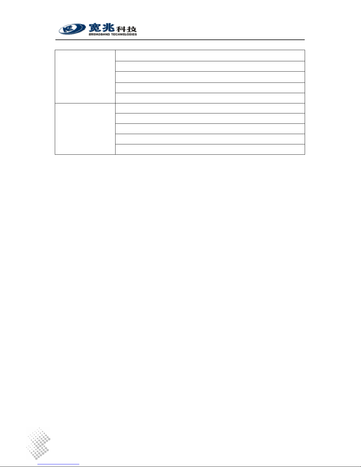
Interface Function Description
Life Line RJ11 interface to
PSTN
If a customer prefer, he may retain one analogue line
provided by PSTN service provider. This line can be
connected to the Life interface and is shared amongst all
phones and fax machines. When there is power outage,
outgoing calls from all local phones and fax machines will
be routed to this escape interface. However, only one local
phone can make call at one time.
2.2 Physical Specification
Dimensions 250mm (W) ×45mm (H) ×180mm (D)
Weight About 1 kg
Power Supply 12V DC
Power < 15W
Operating
Environment
Temperature 0 ~ 50 , ℃℃Relative humidity 10% ~ 90%, no-condensing
of humid is tolerated
Storage
Environment
Temperature -30 ~ ℃ 65 ,℃ Relative humidity 5% ~ 95%, no
condensing of humid is tolerated
Interface 1 10M/100M Ethernet port for WAN
1 10M/100M Ethernet port for LAN
4 (iSurf 1004) / 8 (iSurf 1008) POTS Interface
1 PSTN escape interface
1 Console Configuration Interface
1 12V DC Power Interface
Switch 1 Reset switch
Indicator Light PWR: Power Indicator
RUN: System Status Indicator
WAN: Wide Area Network Status Indicator
LAN: Local Area Network Status Indicator
POTS: 4 (iSurf 1004) / 8 (iSurf 1008) POTS Interface Status Indicator
Reliability System Available Time> 99.99%
MTBF > 100 K hours
Fault Recovery Interval < 2 min
2.3 Data Network Features
IEEE802.3 10Base Ethernet
IEEE802.3u 100Base Ethernet (Fast Ethernet)
Supported Protocol
IEEE802.3x Full / half duplex flow control
Duplex Auto Sensing
MAC Address 1 MAC address assigned by the vendor
MTU 1528 Bytes
iSurf 1004/1008 User Manuals
Page 5
1 IP address is required for WAN interface. The IP address for WAN
interface is typically allocated by the service provider by DHCP or
PPPoE.
IP Address
The default IP address for the LAN interface is 192.168.0.1.
IP Address
Acquisition
Support static IP address, DHCP and PPPoE
Data Switching
Mode
Store and Forward
148810pps with no packet inspection for QoS Throughput
600pps with packet inspection and tagging for QoS
Routing Protocol Static Route
Classification of internal traffic to SIGNALING and VOICE Traffic Classification
Classification of external traffic from LAN port to SIGNALING, VOICE,
and DATA based on deep packet inspection and stateful traffic learning
VLAN Tagging 802.1Q VLAN Tagging based on traffic classes
Marking of 802.1p bits based traffic classification QoS Marking
Marking of IPV4 DSCP field. based on traffic classification
QoS Scheduling Internal VOICE and SIGNALING is always prioritized against external
traffic.
Rate Limiting Rate Limiting on Ingress interfaces, configuration at 64K granularity
NTP Support NTP protocol and capable of acquiring timing from NTP
servers.
VPN Pass-through Support L2TP, PPP, IPSec pass-through
2.4 Voice Features
SIP Session Initiation Protocol
RTP Real Time Transfer Protocol
Supported Protocol
RTCP Real Time Transfer Control Protocol
Voice Encoder G.711,G.723,G.726,G.729
Noise Control Comfort Noise Generation & level control
Echo suppressing G.165/G.168-2000 echo suppress
Silence process Silence detection and suppressing
FAX T.30, T38
Delay and Packet
lose Process
Delay and jitter control/ Packet lose equalization
POTS Interface > 5km
Convergence Rate 1:01
Supported Service
PSTN Basic Service、PSTN supplementary service and value added
service
iSurf 1004/1008 User Manuals
Page 6
Under good network condition PSQM mean value <1.5;
Under bad network condition (PLR=1%,Jitter=20ms,
Delay=100ms) PSQM mean value<1.8;
Under worst condition (PLR=5%,Jitter=60ms,Delay=400ms)
Voice Quality
Perceptual Speech
Quality
Measurements
PSQM mean value <2.0
Under good network condition MOS>4.0;
Under fair network condition (PLR=1%,Jitter=20ms,
Delay=100ms) MOS>3.5;
Under worst condition (PLR=5%,Jitter=60ms,Delay=400ms)
Voice Quality Mean
Opinion Score
MOS>3.0
2.5 Management Features
iSurf supports the following configuration and management methods
• Local Console Management
• Remote Telnet Management
• Web based Management Interface
• SNMP Interfaces to Advanced Network Management Systems
iSurf 1004/1008 User Manuals
Page 7
3 Getting Started
3.1 Packing list
Unpack iSurf product package carefully. Every iSurf product package comes with the following
items:
Table 3 Packing list of an iSurf Package
Description Quantity
iSurf IAD 1
12V DC Power Adapter 1
Ethernet Cable 1
RS232 Serial Console Cable 1
User Menu 1
Product Warranty Card 1
If you find any of the items is missing, please contact our local distributor immediately.
3.2 Connecting other Customer Premise Devices
It is recommended that iSurf are installed in a clean, dry and ventilated indoor environment. Keep
the device far from other heat sources and do not block ventilation slots at both side of the device.
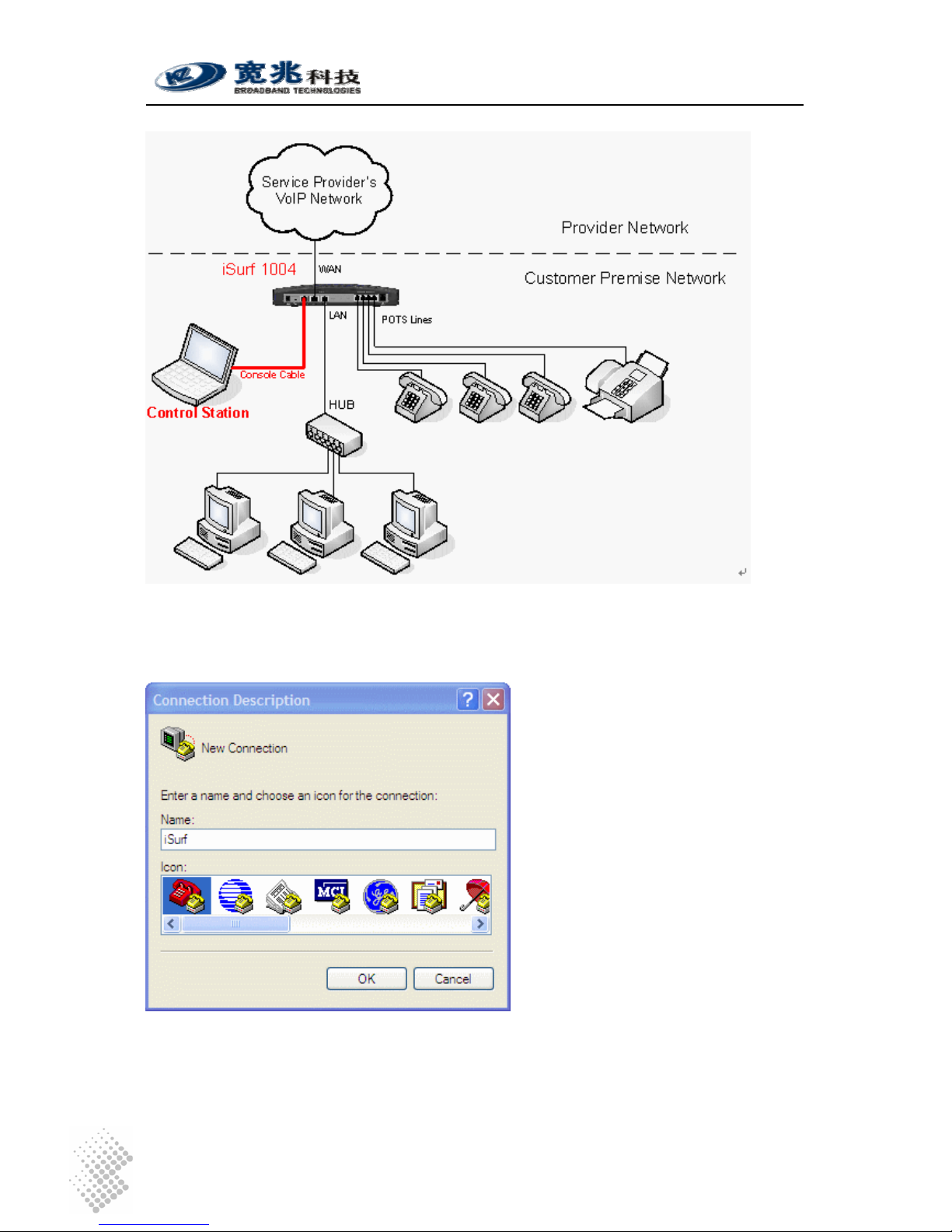
Figure 2 Connections from iSurf to other Customer Premise Devices

iSurf 1004/1008 User Manuals
Page 8
Figure 2 illustrates connections from iSurf 1004 to other devices in a customer premise network.
1. POTS lines: Connect phones and fax machines to one of the RJ-11 jacks in rear panel.
2. WAN: Connect an Ethernet cable from xDSL/Cable modem to the RJ45 jack for WAN
(Wide Area Network) in rear panel
3. LAN: Connect an Ethernet cable from your computer ’s network adapter to the RJ45 jack
for LAN (Local Area Network) in real panel. An Ethernet switch or hub can also be used
to provide more Ethernet ports for more computers.
4. Power: After connect to power source, iSurf will start up automatically. It may take 30
seconds or longer for iSurf to fully complete the boot-up process.
In Figure 2 all four FXS ports of an iSurf 1004 have been fully utilized. If there are still idle ports
available, it is recommended, but not necessary, to power off iSurf before connecting new
devices.
3.3 Example Configuration
This section shows a quick example on how iSurf works with an service provider’s offering voice
services based on SIP (Session Negotiation Protocol).
Caution Configuration data discussed in this section is for illustration
purpose only. Actual configuration may differ depending on your
service provider network scenario.
SIP is an application layer signaling-control protocol used to establish, maintain, and terminate
multimedia sessions. Multimedia sessions include internet telephony, conference, and other
similar applications involving such media as audio, video, and data.
iSurf may initiates SIP call requests to other SIP capable node. If an calling party knows IP
address of the called party, the calling party may initiate a call request directly to the called party.
However, in a large network, such intelligence is difficult to maintain by end points. Service
providers’ infrastructure plays an vital role in facilitating telecommunications communication.
A large scale telecommunication network typically consists of the following components:
SIP Clients: SIP Clients, also widely referred as User Agents, typically represent
subscriber devices that are capable of initiating and accepting SIP calls. A SIP
client is identified by its SIP address, e.g. bob@myserviceprovider.com. The
format of SIP addresses is very similar to an email address. In many
networks, it may also appear as <Dial Number>@myserviceprovider.com.
Dial Number is a string of numeric digits. SIP Addresses and Dial Numbers
should be provided by Service Provider before commissioning an iSurf.
Registrar: Registrar authenticate SIP Clients and maintain their status. Each SIP Client
is required to register itself to Registrar periodically and announce its latest IP
address. In this way IP addresses of all SIP clients in the network are updated,
Proxy may look up IP address of a called party using Dial Number or SIP
address. The IP address or host name of Registrar should be provided by
Service Provider to configure an iSurf. In certain networks, Proxy may forward
registration messages to Registrar, as such IP address of Registrar can be
specified the same as the IP address of Proxy.
Proxy Proxy performs network address translation, and assists in locating called

iSurf 1004/1008 User Manuals
Page 9
party. Proxy may also inter-work with other service providers’ networks if the
called party is outside boundary of the network, while a end user may not
have the permission to do so. The IP address or hostname of the Proxy
should be provided by Service Provider.
Figure 3 SIP Capable Network Elements in a VoIP Network
3.3.1 Establish Network Connectivity
Connect WAN port of iSurf to an Ethernet port provided by service provider, e.g. a port in Cable
Modem or DSL Modem. Assuming the network do not require any authentication to issue an IP
address, iSurf will acquire an IP address for its WAN interface through DHCP.
Default IP address of iSurf’s LAN interface is 192.168.0.1. By default iSurf also serves as an
DHCP server for the LAN segment. It allocates addresses in 192.168.0.2-244 range to
requesting IP address by DHCP. NAT is enabled between the LAN segment and the WAN
segment.
Change TCP/IP settings of your PC to DHCP mode. Connect your PC to LAN interface of the
iSurf IAD, make sure your PC acquires an IP address. You should be able to PING the IP
address LAN interface of iSurf IAD 192.168.0.1, otherwise please follow guidelines in Section 4.1
to troubleshoot. Launch web browser to visit http://192.168.0.1
. A small window will pop up and
ask for user name and password. Fill in the default user name and password.
Username: admin
Password: admin
iSurf 1004/1008 User Manuals
Page 10
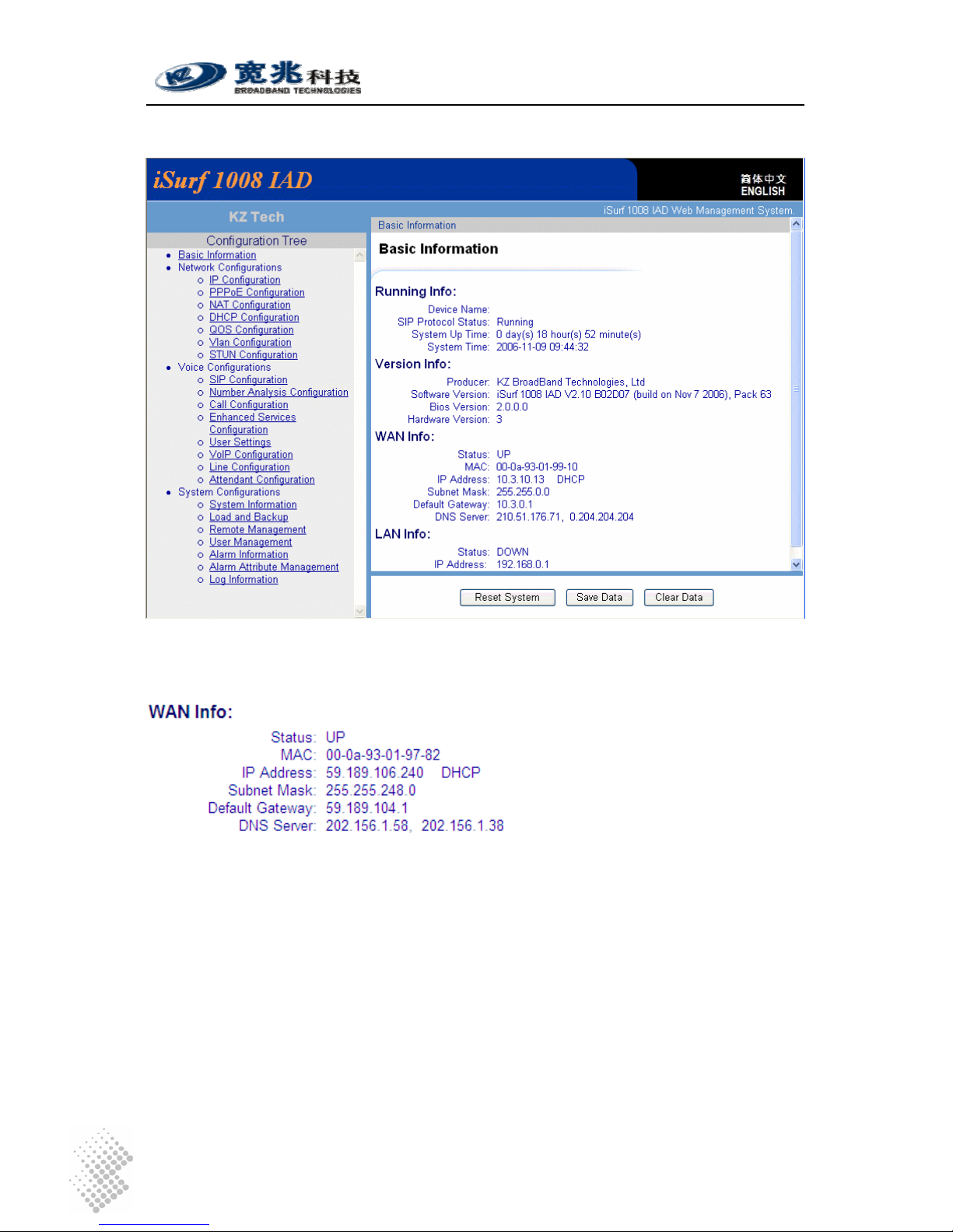
You will be brought into the web administration interface provided by the iSurf IAD.
Figure 4 iSurf's Web Management Interface
Verify that WAN interface is up, otherwise follow guidelines in later sections to trouble shoot.
3.3.2 Example SIP Configuration
The example configuration assumes the following concerning the service provider.
Registrar’s IP Address Not used. Proxy server forwards relevant SIP
messages to Registrar.
Proxy’s IP address 202.156.1.248
Dial Number of the analogue phone 85412006
SIP Address for analogue Phone 85412006@myisp.net
Password for the above SIP address: pass2006
Each iSurf 1004 unit provides four interfaces for POTS devices. The following configuration
assumes an analogue phone is connected to FXS port 1.
iSurf 1004/1008 User Manuals
Page 11
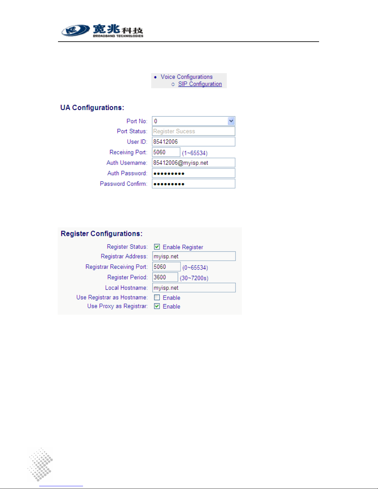
Click on “SIP Configurations” in the left area of the browser window:
Fill in the following in “UA Configuration” section.
UA stands for User Agent. Internally FXS ports are counted from 0. Phone port 1 maps to Port No
0 internally. The “User ID” maps to dial number. Apply settings after changes are made.
Next comes to Registrar configurations.
When “Enable Register” is enabled, registration message will be sent out. However when “Use
Proxy as Registrar” is enabled, registration messages are sent to the IP address of Proxy.
When “Enable Register” is disabled, iSurf may be configured for point to point communications,
which is typically used by multi-site enterprises. Apply settings after changes are made.
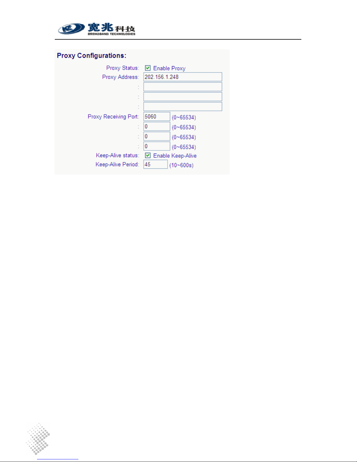
Next comes to SIP Configurations.
iSurf 1004/1008 User Manuals
Page 12
If more than one Proxy Address are supplied, an iSurf IAD will try each Proxy sequentially if a
request times out. Apply settings after changes are made.
After complete all settings, you may uncheck “Enable Register” and apply settings to de-register
the iSurf. Check “Enable Register” and Apply settings again to perform a new registration. If an
registration is successful, the “Port Status” under “UA Configurations” should show “Register
Success”.
Configure another iSurf in a similar way. The only difference is the Dial Number and SIP Address.
Dial Number of the analogue phone 85412010
SIP Address for analogue phone 85412010@myisp.net
If both iSurf register successfully, make a call from the phone 85412006 to another phone
85412010 by dialing 85412010 at the phone pad.
Save configuration data by pressing [Save Data] button.
iSurf 1004/1008 User Manuals
Page 13
4 Managing iSurf
iSurf supports four management methods: CONSOLE, TELNET, WEB base and SNMP
management, from local or from remote central offices.
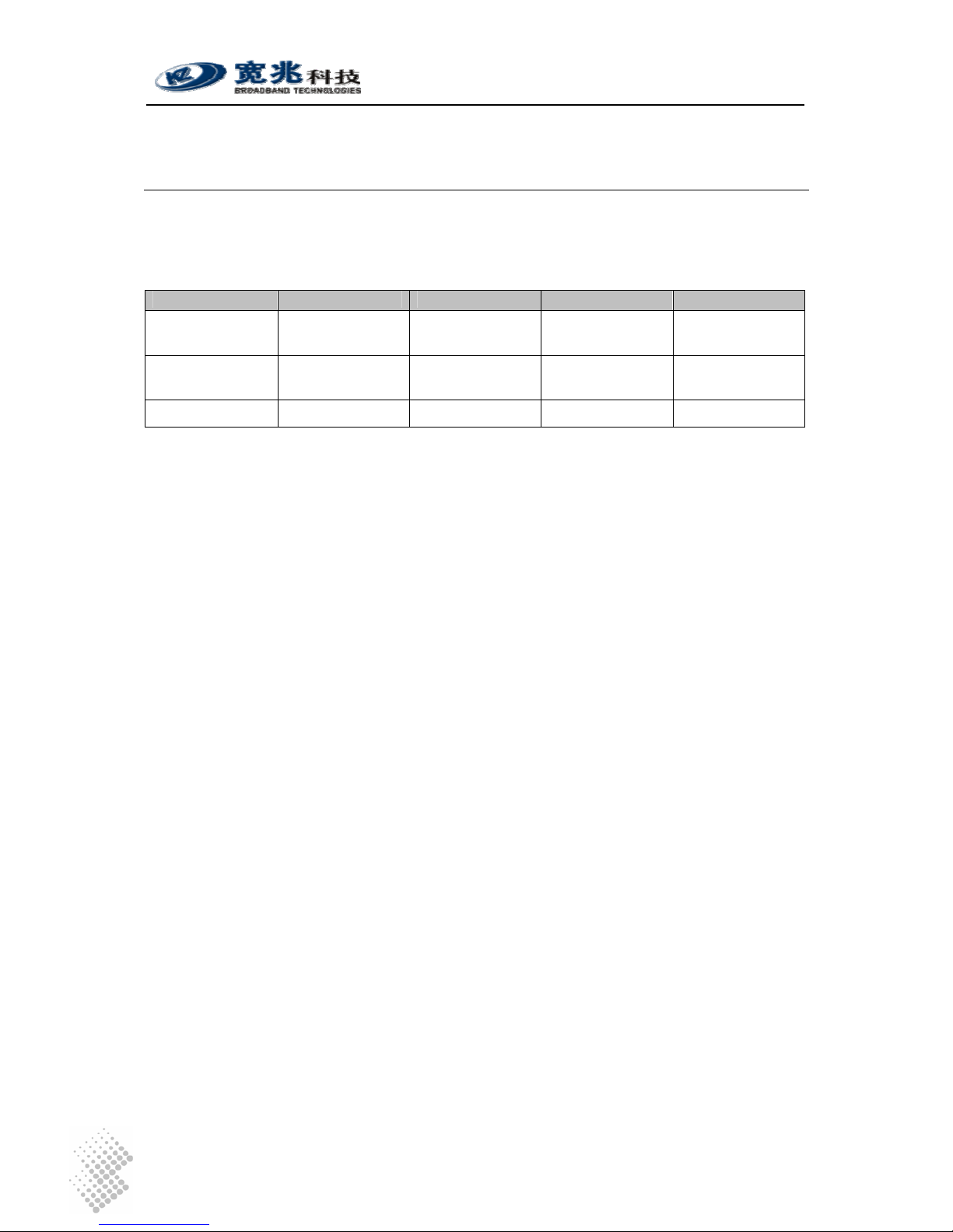
Table 4 Comparison of Management Methods
Console Telnet Web SNMP
User Interface Command Line Command Line Graphic User
Interface
Graphic User
Interface
Management
Distance
Local Local or Remote Local or Remote Local or Remote
User credentials Not encrypted Not encrypted Encrypted Not encrypted
User name and password are required for access to management functions. There are two levels
or privileges: administrators’ privilege and normal users’ privileges.
• Administrator’s privilege is designed for service providers to provision an iSurf IAD,
before selling or leasing out iSurf to end users. By supplying administrator’s user name
and password, a technician has access to all configurations of an iSurf IAD. Default user
name for administrator’s privileges is “admin”. Default password is “admin”.
• Users’ privilege is provisioned for end users to make limited changes of configurations for
an iSurf IAD, Most of other configuration are not visible to when accessed with normal
user’s privileges. Default user name for administrator’s privileges is: user. Default
password is “user”.
4.1 Managing iSurf via Console
iSurf can be managed via console port. Any PC with a serial communication port and installed
with Terminal emulation application, e.g. HyperTerminal software as part of Windows operating
system, can be used as an console to manage iSurf IAD.
Connect your PC’s COM port (DB9) to the Console port (RJ45) using the special console cable
provided with iSurf.
iSurf 1004/1008 User Manuals
Page 14
Figure 5 Manage iSurf via Console
Select Start – Programs – Accessories – Communication- Hyper Terminal from your PC. You will
be prompted to provide a name for the new connection. Type in “iSurf” in the name field.
Figure 6 Define a Connection in HyperTerminal
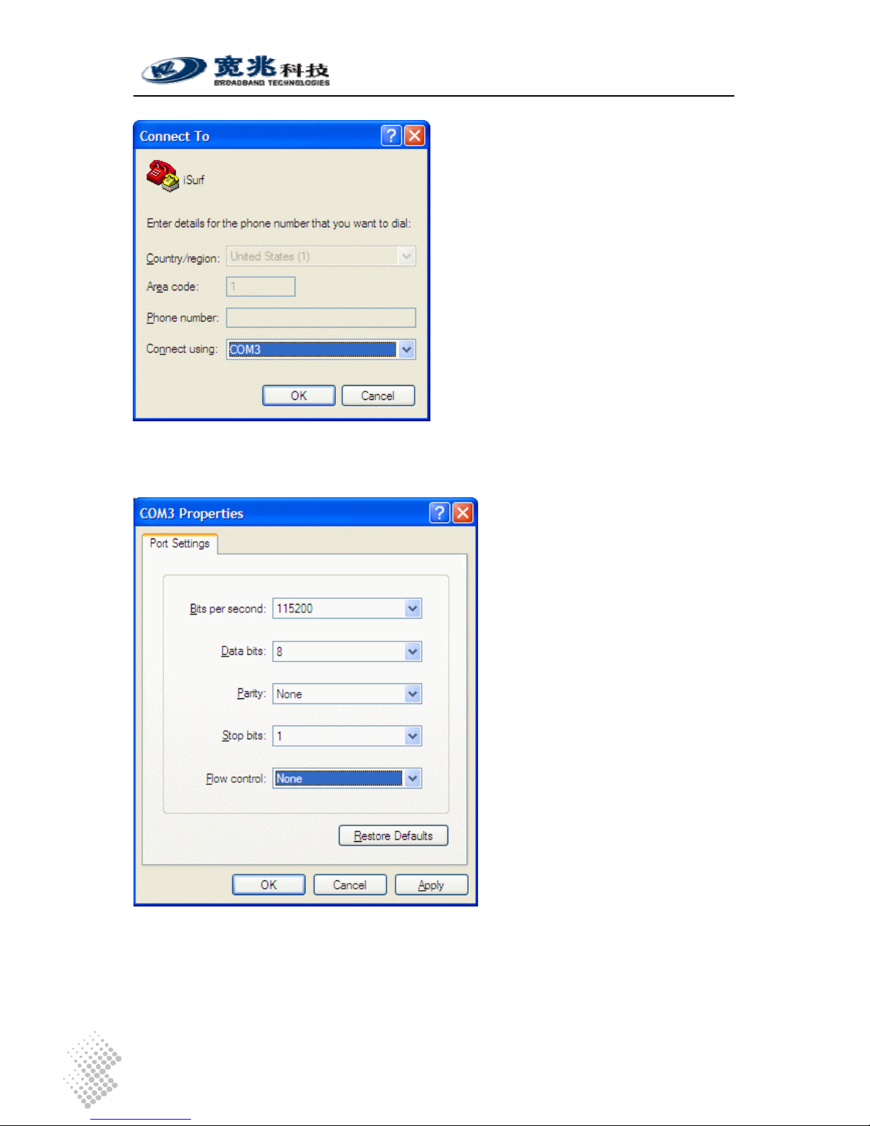
Click on the drop down list right to “Connecting using:”, and select the right port that is connected
to the console port of iSurf. In the example below, COM3 port is used.
iSurf 1004/1008 User Manuals
Page 15
Figure 7 Select Communication Port in PC
Press “OK” button, a new window titled “COM3 Properties” will pop up:
Figure 8 Setting Property of Communication Port in PC
Set the following parameters for the COM port:
Bits per second: 115200
Data bits: 8

iSurf 1004/1008 User Manuals
Page 16
Parity: None
Stop Bits: 1
Flow Control: None
Press “OK” button to close the window in Figure 8. Return to the command line window in
HyperTerminal. Hit “Enter” for a few times, a prompt should appear:
Figure 9 Console Access to Management Interface
At this point, communication between PC and iSurf has been established. iSurf is ready to accept
command issued in the HyperTerminal window.
>> show interface all
Index Interface Address Mask Status
1 lo1 127.0.0.1 255.255.255.0 static/up
2 lan1 192.168.0.1 255.255.255.0 static/up
3 wan1 59.189.106.240 255.255.248.0 dhcp/up
4.2 Managing iSurf by Telnet Access
To Telnet into iSurf, the IP address of its WAN interface or LAN interface must be known.:
• Default IP address for the LAN interface is 192.168.0.1, unless the configuration has
been modified.
• The IP address for WAN interface is usually acquired from service provider’s network
after iSurf boots up.
If neither of these two address is known, the reader is advised to investigate IP address by
following instructions given in Section 4.1.

iSurf 1004/1008 User Manuals
Page 17
4.2.1 Telnet Access to iSurf from LAN Segment
The reader may Telnet into iSurf by specifying IP address of iSurf’s LAN interface. Default IP
Address of iSurf’s LAN interface is 192.168.0.1.
Connect LAN port of the Control Station (a PC) directly to the LAN port of iSurf. Figure 10 shows
an indirect connection between the Control Station and iSurf, via an Ethernet hub.
Figure 10 Telnet Access into iSurf from LAN Segment
iSurf also acts as an DHCP server for hosts in LAN segment by default, unless this feature is
disabled. Control Station may dynamically acquires an IP address from iSurf’s built-in DHCP
server.
After IP layer connectivity is established between the Control Station and iSurf, the reader may
Telnet into the iSurf.
4.2.2 Telnet Access from WAN Segment
The reader may also Telnet into iSurf IAD by specifying IP address of iSurf’s WAN interface.
Access from WAN interface is very helpful for remote troubleshooting.
CAUTION Telnet from remote location is not recommended as user name and
password are sent in clear text. Malicious users may sniff IP packets
and find administrator’s credentials easily.
The WAN interface of iSurf does not have an static IP address by default. iSurf must be properly
configured to acquired an IP address, usually by DHCP or PPPoE, from service provider’s
network.

iSurf 1004/1008 User Manuals
Page 18
When the iSurf IAD is operational, the WAN interface must have acquired an IP address. Support
technician may seek end user’s help to find out IP address of the WAN interface of an iSurf IAD
located in customer premise. The most easy way for end users is to follow the instructions
outlined in Section 4.3.1. End users may be given a user name and password with lower
privilege to access limited information stored in an iSurf IAD.
Figure 11 Telnet into iSurf IAD from WAN Segment
4.3 Managing iSurf IAD from a Web Brower
It is also possible to manage iSurf IAD from a web browser in a remote host, for example,
Internet Explorer in Windows operation systems.
The reader has the option to access the IAD from the LAN segment, or from the WAN segment.
• The default IP address for the LAN interface is 192.168.0.1, unless the configuration has
been modified.
• The IP address for the WAN interface is usually acquired from service provider’s network
after iSurf boots up.
If neither of these two addresses is known, the reader is advised to investigate IP address by
following instructions given in Section 4.1.
4.3.1 Access iSurf’s from LAN Segment
Connect the LAN port of Control Station (a PC) directly to the LAN port of iSurf, or in-indirectly via
a Ethernet hub or switch.

iSurf 1004/1008 User Manuals
Page 19
Figure 10 shows an indirect connection between the Control Station and iSurf IAD via an hub.
iSurf IAD acts as an DHCP server for hosts in the LAN segment by default, unless this feature is
disabled. The Control Station may dynamically acquires an IP address from iSurf’s built-in DHCP
server.
After IP layer connectivity is established between the Control Station and iSurf IAD, the reader
may launch an browser and specify http://192.168.0.1
in the address bar. A window will pop up
requesting user name and password.
Figure 12 Logon Web Page
Input user name and password then click on “OK” button. After successful log on, the welcome
page of web management interface will appear.
4.3.2 Access iSurf’s from WAN Segment
Service providers also manage an iSurf IAD from remote, by specifying the IP address of the
WAN interface of an iSurf IAD’s in a customer’s premise. Access from the WAN interface is very
helpful for remote troubleshooting.
The WAN interface does not have an static IP address by default. An iSurf IAD must be properly
configured to acquired an IP address, usually by DHCP or PPPoE, from the provider’s network.
When a iSurf IAD is operational, the WAN interface must have acquired an IP address. Support
technician may seek end user’s help to find out the IP address of WAN interface of an iSurf IAD
located in customer premise. The easiest way for end users is to follow the instructions outlined
in Section 4.3.1. End users may be given a user name and password with lower privilege to
access limited information stored in an iSurf IAD.
4.4 SNMP Method
iSurf supports SNMP v2 management protocol. iSurf devices can be managed by MIB Browser,
HP OperView or other network management systems.

iSurf 1004/1008 User Manuals
Page 20
5 System Configurations via Web Interface
Type in IP address of the iSurf in a web browser, e.g. http://192.168.0.1, iSurf will invoke its
internal HTTP server to respond to further request from users.
5.1 Welcoming Page
Figure 13 shows the Welcome page of web management interface of an iSurf 1004 IAD.
Figure 13 iSurf's Web Management Interface
5.1.1 Configuration Tree
The left frame in the above web page shows the Configuration Tree, which provides links to
detailed configuration pages.
Configuration management of iSurf 1004 IAD is categorized into three major groups:
• Network configurations
• Voice configurations
• System configurations
Items in Configuration Tree are arranged from top to down according to frequency of use.
However in this manual, we will start with discussions on System Configuration, followed by
elaborating Network Configuration and Voice Configuration in other sections.

iSurf 1004/1008 User Manuals
Page 21
5.1.2 Detailed Configuration Window
The middle right frame in the browser window has the largest display area. It is used to display
detailed configuration. Certain configuration pages can not be fully displayed in the screen.
Scroll the vertical bar down in the right to view information that may not be displayed.
5.1.3 Reset System, Save Data and Clear Data
The lower right frame of the web page has three buttons:
Effective configuration data are stored in RAM(Random Access Memory). Once iSurf is powered
off, all effective configuration in RAM will be lost, unless they are Saved into non-volatile flash
memory.
Information Users are advised to Save configuration changes, after Applying
changes in the Detailed Configuration Window.
Effective system data can be saved, by clicking on [Save Data] button, into non-volatile flash
memory, which can be reloaded automatically every time when IAD boots up.
Resetting system will shutdown all processes and reboots iSurf. The system software will be
reloaded. The system software will read configuration data saved in non-volatile flash memory
during the boot process.
5.2 System Information
Items in Configuration Tree are arranged according to frequency of use. However this manual will
start with System Configuration, which is the third group in the Configuration Tree .
5.2.1 Basic System Information
Click on “System Information” in the Configuration Tree in the left frame of browser window. The
following system information will be displayed in the detailed configuration frame:
Basic system information of the device is shown, such as service state, IP address, MAC,
System Version. The information cannot be modified.

iSurf 1004/1008 User Manuals
Page 22
The device name is shown here. It can be modified by inputting a new name.
5.2.2 System Time
Click on “System Information” in the configuration tree in the left frame of browser window. The
System Time will be displayed in the middle of the web page. The web page does not update the
displayed time automatically. Click on [Refresh] button to view current system time.
To set iSurf’s system time, type in all the fields and click the [Apply] button.
iSurf IAD also supports the NTP(Network Timing Protocol) to synchronize its system time with an
clock source with higher accuracy. NTP server can be configured with ntp commands in the
console or telnet interface.
5.2.3 Contact Info Configuration
The Contact Information can be modified in the text box, such as company name, admin name,
and contact phone number. Click on [Apply] button to confirm the changes. Click [Save Data]
button to save the data into non-volatile memory.

iSurf 1004/1008 User Manuals
Page 23
5.3 Load and Backup
This section demonstrates “Load” and “Backup” transaction via a web management interface. Let
us start with discussion of a few terminologies:
Program refers to the file which contains binary instruction sets that controls the
iSurf system.
Data refers to the file which contains network and user specific configuration
Load refers to transferring of system program file or configuration data file
from an external host into an iSurf IAD.
Backup means saving of configuration data file from an iSurf IAD to an external
host.
TFTP and HTTP protocols are supported to Load and Backup new firmware and/or system
configuration files. iSurf may also be upgraded by the element manager iManager 2000.
Configuration data can be backed up from iSurf to an external host, or restored from external
computer into an iSurf IAD. The external host must have IP connectivity with the iSurf IAD.
5.3.1 Load or Backup over TFTP
An external host running TFTP server can be used to backup iSurf configuration data, or restore
configuration data to iSurf IADs.
Information The external host in this case serve as the TFTP server. The iSurf
IAD serves as a TFTP client.
5.3.1.1 Load System Files from a TFTP Server
The steps of Load system software or configuration via TFTP are as follows:
1. Obtain the correct release of program file, the program file in this example is named
“iad.prg”.
2. Obtain the IP address of the TFTP server. The IP address of the external host is
192.168.0.18
3. Type IP address of the TFTP server in the “TFTP server address" field.
4. Choose the type of the loaded files as "Program" in the “File Type" field.
5. Type the loaded file name in the "File Name" column.
6. Click the “Load”.
7. Reset the system after successful update.

iSurf 1004/1008 User Manuals
Page 24
Typically it takes 20 seconds or longer to upload a firmware.
Caution Do not close WEB browser window during the process. Otherwise
the system configuration may be corrupted.
5.3.1.2 Backup Configuration Data to an TFTP Server
The steps of backup over TFTP are as follows:
1. Obtain the IP address of the TFTP server.
2. Type the IP address of the TFTP server in the “TFTP server address" field.
3. Choose the type of the backup file as "Data" in the “File Type" list.
4. Input the backup file name in the "File Name" file.
5. Click "Backup" button. Examine the whether the backhaul file has been successfully
created.
5.3.2 Load or Backup over HTTP
Similarly, the system firmware and configuration files can be loaded in to iSurf IAD via HTTP
protocol. The configuration files can be backed from the iSurf IAD to the external host.
The external host in this case is the computer which runs the web browser to access the network
management pages.
Information The external host in this case serves as a HTTP client. The iSurf IAD
serves as a HTTP server.
5.3.2.1 Load System Files to an iSurf IAD from a Web Browser
The steps of Load firmware via HTTP are as follows:
1. Obtain the latest version of system firmware. (e.g. iad.prg.)

iSurf 1004/1008 User Manuals
Page 25
2. Choose "Program" as the file type in the “File Type" list.
3. Click the "Browse" button, a dialogue box will appear as shown below.
4. Select the file “iad.prg”, click the “Open” button.
5. Click the [Load] button.
6. Reset system after loading finished.
5.3.2.2 Save system configurations from iSurf IAD
The steps of backup configuration files via HTTP are as follows:
1. Choose the type of the backup file as "Data" in the “File Type" column.
2. Click the “backup" button.
3. Click the “Save” button.
4. Select the file name and click the “Save” button.
Information Many web browsers implemented security features which blocks
downloading of a file. Check your browser settings to if no File Save
dialogue box appears.

iSurf 1004/1008 User Manuals
Page 26
5.4 User Management
iSurf IAD implemented two levels of user privileges, for administrators and end users.
• Administrator’s privilege allows full control of the iSurf system, e.g. system software
upgrades. Administrator’s privilege provides maximum flexibility for service providers to
integrate the iSurf with its network.
• Operator’s privilege allows assess to a subset of features and parameters that are
customer specific. Parameters that are prone to cause operational failure are forbidden
from access, e.g. change of dial number.
The system may support up to 15 users, each user has its user name, privilege level, preferred
language, and password.
User name is the only identifier of the user, which constitute by up to 17
alphanumerical characters, or up to 7 Chinese characters.
Level is the privilege level of a certain user. It could be Administrator or
Operator. Only users with Administrator level may create/modify the
privilege of other accounts.
Language defines default display language of web management pages for a user.
5.4.1 Display Existing Users
Click on “User Management” in the Configuration Tree. The following information will be shown in
the detailed configuration window.
The table on top of the page displays the user accounts that are already provisioned in the iSurf
IAD.
5.4.2 Add Delete and Modify User
Click on “User Management” in the Configuration Tree, The User Management page will be
shown in the detailed configuration window.

iSurf 1004/1008 User Manuals
Page 27
• To Add a new user, type User Name, Level, Language, and Password, then press [ADD]
button.
• To Delete an existing user, select the entry in the Current User table, click on [Delete]
button to delete the user.
• To Modify the credentials of an existing user, select the entry in the Current User table.
The user name, privilege, language and password will be displayed in respective text box.
Make changes and press [Apply] button to effect the changes.
5.4.3 ACL(Access Control List) Management
ACL (access control list) provides enhanced security by restricting access to iSurf IAD according
to IP address of the remote station. Hosts whose IP address in subnets defined by ACLs are
permitted to access the IAD, while the access from other hosts are forbidden.
ACLs are effective for access by telnet, web or SNMP management interfaces.
Click on “User Management” in the Configuration Tree, scroll down the detailed configuration
window. The following information are shown:
An ACL consists of an network IP address(network address) and Subnet Mask, hosts with in IP
address range 10.10.0.1 to 10.10.0.254 are be able to access the system in this case.
In the “Current ACL” table, the first entry shows an entry, with network IP address of 0.0.0.0, and
Subnet mask of 0.0.0.0. It means access from hosts with any IP address are not restricted.
The web page also allows administrators to to add/deleted/modify ACLs.
Warning: Before deleting the default ACL which with network address of
0.0.0.0, the administrator is advised to add its own subnet.
Otherwise the connection will closed, access from any IP address
will be forbidden unless the iSurf IAD is reset.

iSurf 1004/1008 User Manuals
Page 28
5.5 Alarms
iSurf IADs capture system faults and report them in the Alarms Information web management
page. The Alarm information provides traces of fault and helps troubleshooting the device.
• Faults that have not been resolved are reported in the “Current Alarm” page.
• Faults that have been resolved are stored as “History Alarm”. History alarms will not be
removed unless the power supply is cut off.
5.5.1 Current Alarm
Click on “Alarm Information” in the Configuration Tree. All current alarms will be displayed in the
detailed configuration window.
The table below presents an alarm simulated by breaking down the WAN connection.
5.5.2 History Alarm
Click on “Alarm Information” in the Configuration Tree. All current alarms will be displayed in the
detailed configuration window. Click “View History Alarm” in the “Current Alarm” window, historical
alarm will be displayed.
The table below presents historical alarms captured in an iSurf IAD:

iSurf 1004/1008 User Manuals
Page 29
5.6 Alarm Attribute Management
iSurf IAD allows re-interpretation of alarms, but defining the description for each Alarm ID. Such a
implementation also helps the develops to add new types of alarm information in further releases.
Click on “Alarm Attribute Management” in the Configuration Tree, defined alarm information base
will be shown in the detailed configuration window.
5.6.1 Defined Alarms
The following Alarms have been defined in the system:
Table 5 Alarms Defined in the iSurf System
Alarm ID Alarm Description
0x00000101 Node state alarm
0x00000102 Port state alarm
0x00000201 Media interface
0x00000206 H323 Register status
0x00000207 SIP Register status
0x00000801 Memory use status
0x00000802 CPU use status
0x80000104 Duplicate IP Address
0x80000105 Interface status change
0x80000106 Static route status change
0x80000107 Duplicate MAC Address
0x8000020D RAI Outof Upper Value
0x8000020E RAI Outof Low Value
0x80000301 Load file success
0x80000302 Load file failure
0x80000304 Flash data restore failed
0x80000801 CPU Tx packet failure

iSurf 1004/1008 User Manuals
Page 30
0x80000802 CPU ethernet Rx packet loss
0x80000803 CPU ethernet Rx busy
0x80000804 LanSwitch packet Tx collision
0x80000805 LanSwitch packet loss
0x80000806 RTP Rx packet loss
5.7 System Log
iSurf IAD logs major system events automatically and store them in the system log, such as log
in and out, system upgrades, and reset, etc.
Click on “Log Information” in the Configuration Tree, the system log will be shown in the detailed
configuration window.
The chart below shows the system log of an iSurf IAD.

iSurf 1004/1008 User Manuals
Page 31
6 Network Configurations via Web Interfaces
This section discusses the configuration to establish connectivity between an iSurf IAD with a
VoIP core network.
iSurf IAD serves as a gateway for legacy phones and faxes.
• The WAN (wide area network) interface of an iSurf IAD should be used interface with
VoIP core network.
• The LAN interface is primarily used to provide data connectivity to IP hosts, e.g. PCs, in a
customer premise.
Figure 14 iSurf as a Gateway for Customer Premise Network
Warning Although LAN interface may also be used to interface with VoIP
network, it is not advised to do so.
Network configurations concern IP addressing, NAT (Network Address Translation) between the
LAN and WAN segments, separation of voice and data by VLAN, and QoS, etc.
6.1 IP Configuration
Click on “IP Configuration” in the Configuration Tree. The web page in the detailed configuration
frame will show IP address configuration, static routes, and ARP table.

iSurf 1004/1008 User Manuals
Page 32
6.1.1 IP Address Configuration
Chose wan1 or lan1 from the drop down list. The interfaces can be shut down or brought up at
electrical level. When the interface is up, the interface can be enabled or disabled at logical level.
The interfaces may acquire an IP address dynamically, or be given a static IP address.
The configuration of interface lan1 can only be shown but not changeable.
6.1.2 Static Route Configuration
Static routes can be specified. A default route is set by iSurf when wan1 interface acquires an IP
address by DHCP or PPPoE. The combination of Destination 0.0.0.0 and NetMask of 0.0.0.0
means all traffic is sent to the default Gateway, which is 10.224.53.254 in the table.
Multiple static routes to the same destination may coexists simultaneously. Their priorities are
differentiated by respective Pref values. The route with smallest positive Pref value will be
elected as the active route. Negative Pref value indicates that an gateway is not reachable.
6.1.3 ARP table and Configuration
In Ethernet networks, a host must translate an destination IP address to a destination MAC
address at data link layer, in order to send an IP packet to another host in the same LAN
segment. Such an translation is achieved by looking up an ARP table. An example is shown in
the ARP table. If no match can be found, the IP packet is sent to the MAC address of default
gateway.

iSurf 1004/1008 User Manuals
Page 33
Entries in the ARP table is learned through Address Resolution Protocol, which defined a number
of ways for network elements in a network elements to announce its own MAC address, to
inquire an MAC address for certain IP address by broadcasting, etc.
Entries in the MAC table can be also modified if necessary.
6.2 PPPoE Configuration
PPPoE is widely used to allow per flow traffic control in service provider’s network.
The configuration is relatively simple. Enable PPPoE feature and fill in username and password.
Apply the settings. Save the configuration. Reset iSurf to effect the changes. PPPoE feature by
default is applied to the wan1 Ethernet interface.
Notice iSurf IAD must be reset to effect PPPoE configurations changes.
6.3 NAT Configuration
Public IP addresses has been depleting with explosive growth of the Internet. As such many
private networks, e.g. corporate networks or customer premise networks use private IP
addresses. These private networks may use overlapping address and is not reachable by hosts
from public domain by routing.
NAT(Network Address Translation) allows multiple hosts with private IP addresses to share one
public IP address, which is usually assigned to the WAN interface. The Source Address, and
Source Port fields in the IP header of packets from private LAN segments, are translated by iSurf
IAD to the public IP address of WAN interface, and an un-used port.

iSurf 1004/1008 User Manuals
Page 34
NAT feature is enabled by default. The “Maximum Session of Each IP” limits the over loading of a
public IP address. It also implies that maximum 256 hosts may be accommodated in the LAN
segments.
6.4 DHCP Server Configuration
iSurf may serve as an DHCP server for the LAN segment.
Click on “DHCP Server Configuration” in the Configuration Tree. A few aspects of DHCP Server
feature can be specified in the detailed configuration frame in the right area of browser window.
By default this DHCP server feature is enabled for LAN segment.
Note NAT must be enabled to if DHCP server is enabled. DHCP server is
enabled by default.
A default IP address pool is allocated by the iSurf IAD. It is not recommend to change this
settings in general. If readers do wish to specify an IP pool manually, please be reminded that the
Gateway for LAN segment should be the IP address of iSurf’s LAN interface.
Notice The Gateway for LAN segment is usually the LAN interface of an
iSurf IAD. If the IP pool for DHCP server is modified to another
subnets, e.g. 192.168.1.0/24, the Gateway and IP address for the LAN
interface iSurf should be modified accordingly.

iSurf 1004/1008 User Manuals
Page 35
As an option, DHCP server may provide a few DNS servers’ to client PCs requesting an IP
address.
When wan1 interface acquires an IP address from the network, it is likely that information of DNS
servers is provided by the DHCP servers in the network. Manual setting is not necessary.
It is also possible to manually specify DNS server address in the table above.
6.5 QoS Marking and VLAN Configuration
VLAN(Virtual Local Area Network) allows separation of traffic by an VLAN ID at layer two of the
seven-layer OSI network model. VLAN may facilitate implementation of security measures, and
QoS treatment.
The iSurf IAD internally classifies traffic into three types, Voice, Signaling, and Data. The traffic
types can be tagged with designated VLAN ID.
All ingress traffics from LAN port are treated as data. More advanced techniques are discussed
in Section 6.5.3.
6.5.1 VLAN Configuration
Click on “VLAN Configuration” to access configuration related to VLAN and QoS.
VLAN tagging at wan1 interface can be enabled or disabled. VLAN ID for Voice, Signaling, and
Data can be designed in this section. .
6.5.2 QoS Configuration
Classified traffic can be marked with certain QoS priorities, at layer two or layer three of the

iSurf 1004/1008 User Manuals
Page 36
seven-layer OSI network model. At layer 2, 802.1p bits are used for QoS Marking. At layer 3, the
DSCP field in IP header is used for QoS marking.
6.5.3 Classification of Ingress Traffic
By default all ingress traffic from LAN port are treated as Data.
In response to one of our customer request, more advanced techniques has been developed, to
differentiate voice and signaling traffic generated by soft SIP user agents, running on PCs in LAN
segment. At the time the document is written, web based management interfaces are not fully
developed yet. This feature is available through command line only, accessed via either console,
or telnet.
The example below illustrates ingress traffic classification based on TCP/UDP port.
/*======== Set ingress flow(data/voice/signal) classification by ip_dscp/trans_port
for LAN port ========*/
MAIN>>config>show lan-qos-classify
Lan Qos Classify disable!
------ IP DSCP Classify info -----------------------------
------ TCP Port Classify info -----------------------------
------ UDP Port Classify info -----------------------------
MAIN>>config>lan-qos-classify dscp enable voice 15
MAIN>>config>lan-qos-classify dscp enable signal 16
MAIN>>config>lan-qos-classify trans-port add signal tcp 80
MAIN>>config>lan-qos-classify trans-port add signal udp 5060
MAIN>>config>show lan-qos-classify
Lan Qos Classify disable!

iSurf 1004/1008 User Manuals
Page 37
------ IP DSCP Classify info ---------------------------- IP DSCP 15 ----> flow VOICE
IP DSCP 16 ----> flow SIGNAL
------ TCP Port Classify info ---------------------------- Tcp Port 80 ----> flow SIGNAL
------ UDP Port Classify info ---------------------------- Udp Port 5060 ----> flow SIGNAL
/*======== Enable ingress flow(data/voice/signal) classification by ip_dscp ======*/
MAIN>>config>lan-qos-classify enable dscp
MAIN>>config>show lan-qos-classify
Lan Qos Classify base on IP DSCP!
------ IP DSCP Classify info ---------------------------- IP DSCP 15 ----> flow VOICE
IP DSCP 16 ----> flow SIGNAL
------ TCP Port Classify info ---------------------------- Tcp Port 80 ----> flow SIGNAL
------ UDP Port Classify info ---------------------------- Udp Port 5060 ----> flow SIGNAL
/*======== Enable ingress flow(data/voice/signal) classification by trans_port
========*/
MAIN>>config>lan-qos-classify enable trans-port
MAIN>>config>show lan-qos-classify
Lan Qos Classify base on Transport Layer Port!
------ IP DSCP Classify info ---------------------------- IP DSCP 15 ----> flow VOICE
IP DSCP 16 ----> flow SIGNAL
------ TCP Port Classify info ---------------------------- Tcp Port 80 ----> flow SIGNAL
------ UDP Port Classify info ---------------------------- Udp Port 5060 ----> flow SIGNAL
/*======== Device interface info ========*/
MAIN>>config>show interface all
Index Interface Address Mask Status
1 lo1 127.0.0.1 255.255.255.0 static/up
2 lan1 10.10.0.1 255.255.0.0 static/up
3 wan1 192.168.0.3 255.255.255.0 dhcp/up
/*======== Command Line about ingress flow classification for LAN port ========*/
1) "lan-qos-classify trans-port add: <flow(voice|data|signal)> <protocol(tcp|udp)>
<port(u1~65535)>"
2) "lan-qos-classify trans-port delete: <protocol(tcp|udp)> <port(u1~65535)>"
3) "lan-qos-classify dscp enable: <flow(voice|data|signal)> <dscp-value(u0~64)>"
4) "lan-qos-classify dscp disable: <flow(voice|data|signal)>"
5) "lan-qos-classify enable: <type(dscp|trans-port)>"

iSurf 1004/1008 User Manuals
Page 38
6) "lan-qos-classify disable"
7) "show lan-qos-classify"
6.6 STUN Configuration
STUN (Simple Traversal of User Datagram Protocol (UDP) Through Network Address Translators
(NATs)) is a network protocol allowing clients behind NAT (or multiple NATs) to find out its public
address, the type of NAT it is behind and the internet side port associated by the NAT with a
particular local port. This information is used to set up UDP communication between two hosts
that are both behind NAT routers.
Protocols like SIP use UDP packets for the transfer of sound and/or video and/or real-time text
signaling traffic over the Internet. Unfortunately as both endpoints are often behind NAT, a
connection cannot be set up in the traditional way. This is where STUN is useful.
STUN is a client-server protocol. A VoIP phone or software package may include a STUN client,
which will send a request to a STUN server. The server then reports back to the STUN client
what the public IP address of the NAT router is, and what port was opened by the NAT to allow
incoming traffic back in to the network.
By default, a STUN server in the public domain larry.gloo.net has been configured as the
secondary server. The Service Provider may specify address of its own STUN server, if
implemented, as a primary server.
The response also allows the STUN client to determine what type of NAT is in use, as different
types of NATs handle incoming UDP packets differently. There are four main types of NAT:
• full cone NAT,
• restricted cone NAT, and
• port restricted cone NAT.
• symmetric NAT (also known as bi-directional NAT)
iSurf has built in intelligence to work with three of four main types: full cone NAT, restricted cone
NAT, and port restricted cone NAT, by pre-adjust the outgoing SIP messages and voice using
public IP address and source port discovered.
iSurf will not work with symmetric NAT (also known as bi-directional NAT).

iSurf 1004/1008 User Manuals
Page 39
7 Voice Configurations
7.1 SIP Configuration
SIP related configurations concern iSurf as a SIP client, Registrar and Proxy Servers.
Click on “SIP Configuration” in the Configuration Tree to access the related web management
page.
7.1.1 User Agent Configuration
UA stands for “User Agent”. Internally FXS ports are counted from 0. Phone line 1 maps to FXS
Port No 0. “User ID” maps to dial number. Apply settings if changes are made in the above
section.
Next comes to Registrar configurations.
When “Enable Register” is enabled, registration message will be sent out. However when “Use
Proxy as Registrar” is enabled, all registration message is sent to the IP address of the Proxy.
When “Enable Register” is disabled, iSurf may be configured for point to point communications,
which is typically used by an enterprise owning multiple office sites. Apply settings if changes are
made in the above section.

iSurf 1004/1008 User Manuals
Page 40
7.1.2 Proxy Configuration
If more than one Proxy Address are supplied, an iSurf IAD will try each Proxy sequentially if a
requests to an Proxy times out with no responses. Apply settings if changes are made in the
above section.
After completing all settings, you may uncheck “Enable Register” and apply settings to deregister the FXS port. Check “Enable Register” and apply settings again to perform another
registration. If an registration is successful, “Port Status” under “UA Configurations” should show
“Register Success”.
7.1.3 Mapping of SIP Configuration to SIP Messages
Different VoIP network equipment vendors may have implemented SIP protocol in different ways.
Table 6 summarizes the use of configuration values in various SIP messages.
Table 6 Mapping of Configuration to SIP Messages
Usage in SIP Messages
REGISTER and INVITE
Message
Other SIP Messages
User ID
the "username" part of SIP
URI in From, To, Contact
attributes, e.g. "85412006" in
85412006@myisp.net. (The
"host" part of SIP URI is taken
from "Local Hostname" field.)
the "username" and
"displayname" part of SIP
URI in From, To, Contact
attributes
the "username" and
"displayname" part of
SIP URI in From,
Contact headers
Auth ID
the username used for digest
authorization in REGISTER
and INVITE requests
the "digest username" in
Authorization attributes
usually not used
Auth
Password
the password used for digest
authorization in REGISTER
and INVITE requests
used to calculate the
"response" in Authorization
attributes
usually not used
Registrar
Address
the "request URI" in
REGISTER request. It could
be a domain name, or an IP
address.
Request-URI, for example
sip:mysip.com. Not used in
INVITE message.
usually not used

iSurf 1004/1008 User Manuals
Page 41
Local
Hostname
the "host" part of SIP URI in
From, Attributes. It could be a
domain name e.g. "mysip.com"
in , or an IP address.
("username" is taken from
User ID field.)
the "host" part of SIP URI
in From, To attributes
the "host" part of SIP
URI in From, To
headers and RequestURI
Proxy
Address
the destination IP address to
which SIP messages are sent
to. It does not affect the
content in SIP messages.
the destination IP address
to which SIP messages
are sent to
the destination IP
address to which SIP
messages are sent to
In SIP standards, the “User ID” could be a mix of alphabetic and numeric digits. However, in a
network with analogue phones, “User ID” is recommended to use numeric digits only as iSurf
takes user inputs from phone pad to construct “User ID” of the called party.
The “User ID” field should consist of numeric digits only.
7.2 Number Analysis Configuration
iSurf IAD collects dial numbers from external phone or fax. Dialed digits are analyzed before
being sent out to other element in a VoIP network. Dial numbers can be modified according to
specific needs. Rules can be setup to modified a dial number, if it meets certain condition.
Click on “Number Analysis Configuration” in the Configuration Tree. Conditions and associated
actions on dial numbers are displayed in the detailed configuration window.
The conditions are defined in Call Route Configuration section. The actions are defined in
Number Change Configuration section.
7.2.1 Conditions to Modified Dial Numbers
The Current Call Route List table shows conditions that triggers certain action on a dialed
number string.
• “Number Prefix”, “Min Length of Number”, and “Max Length of Number” are used in

iSurf 1004/1008 User Manuals
Page 42
combination to define a condition.
• “Route Address” may specify another SIP capable node to route a call. If this field is left
empty, configuration in User Agents setup applies. This feature was widely used for point
to point calls without involvement of Proxy servers, in early years of VoIP network
evolution.
• “Change Index” specifies the index of an action in “Current Change List” table to be taken,
if a dial number matches with the condition.
Example in the table shows that dial numbers starting with 021, is subject to the change defined
in action 0 defined in the Current Change List.
7.2.2 Number Change Configurations
The “Number Change Configuration” section defines the actions to be taken, if a dial number
meets certain conditions defined in “Call Route Section”.
• “Index” defines the index of action.
• “Type” defines type of changes. Certain digits can be inserted into a dialed number. Digits
in a dial number can also be modified or deleted.
In the example, the change action, defined by entry with “Index” 0 in the “Current C hange List”,
inserts “8541 from the 3
rd
position of the number string.
So an dial number 0212401 is modified to 021 8541 2401 before iSurf IAD sends out a call invite.
7.3 Call Configuration
Call Configuration section defined a few behavior when a call is outgoing or incoming.
Click on “Call Configuration” in the Configuration Tree. The following sections will be displayed in
the detained configuration window:

iSurf 1004/1008 User Manuals
Page 43
7.3.1 Dial Plan Configuration
iSurf collects dial numbers from external phone or fax. Dialed digits are collected as a whole
before they are encapsulated in a call Invite message.
By default iSurf takes five second idle time after the last punch, as completion of user input. Digit
mapping are introduced to allow faster recognition of dial completion. If the dialed digits, input by
user from the phone pad, map with any pattern of DigitMaps defined in this section, collected
digits are immediately processed.
Maximum 500 digit maps can be defined. Each digit map may consists up to 2048 characters. In
the “Dial Plan(DigitMap) Configuration” textbox, each digitmap are separated by an “|” character.
The string “XX.T|XX.#|P|****” consists of four digit maps:
• “*XX” means an asterisk followed by 2 digit of any number. Dial strings matching this
pattern are used for service codes, which allows user interaction by end users, e.g
disable or enable call forwarding. Refer to 7.4 for more detailed information.
• In “XX.T”, “XX” means any digits. “.” means any number of digits. T means a timer. The
entire string means iSurf wait for T seconds after the last user punch on phone pad.
• In “XX.#”, “XX” means any digits. “.” means any number of digits. The entire string means
dialed digits can be processed by press “#” button. Whenever iSurf receives an “#”, iSurf
considers that user inputs has completed, and start processing digits before “#”
immediately.
• The last digit map “****” is defined for use iSurf itself. When user press “****”, the IP
address of iSurf is announced in the ear set of the phone.
When IP Dialing is enabled, iSurf also allows call origination to an IP address input by user from
key pads of a phone.
For example, call to 1000@10.3.50.55:5060
can be dialed by pressing the following numbers:
1000**10*3*50*55**5060.
7.3.2 Multiple Lines using a Single Account
Multiple phones may share one SIP address, or account. Refers User Agent Configuration in 7.1,
Port number 0-3 may use exactly the same “User ID”, “Auth Username”, etc. Phones connected
to any port can make outgoing calls.
In this scenario, if there is a incoming call to the “User ID”, which local phone should ring? This is
defined in “Call Parameter Configuration” in this section.

iSurf 1004/1008 User Manuals
Page 44
A few options are available in the drop down list:
• Early Release First: the line which was released earliest receives an incoming call.
• Random: an incoming call is randomly dispatched to one of the lines.
• Order: an incoming call is dispatched to lines sequentially.
7.3.3 Call Timers
A few timers are defined in this section:
• Ringback Timer: A ringback tone, or audible ringing tone or ringback signal, is the audible
ringing that is heard on the telephone line by the calling party after dialing and prior to the
call being answered at the distant end. When A calls B from an iSurf IAD, if B does not
answer the call, the “Ringback Timer” defines the maximum waiting time after which iSurf
should tear down the the call, (if A does not hang up the phone).
• Ring Timer: A ring tone is the sound made by a telephone to indicate an incoming call.
When B calls A at an iSurf IAD, if A does not answer the call, the “Ring Timer” defines the
maximum waiting time after which iSurf should tear down the call, (if B does not hang up
the phone).
• Busy Timer: when A calls B, if B is busy, the “Busy Time” defines the maximum waiting
time that iSurf should tear down the call, (if A does not hang up the phone).
• Offhook Warning Time: The maximum waiting time after which iSurf should send warning
signals to the line.
7.4 Enhanced Services Configuration
iSurf supports a rich set of supplementary services.
Click on “Enhanced Services Configuration”, the following Supplementary Service Subscription
are displayed in the right frame of browser window:

iSurf 1004/1008 User Manuals
Page 45
iSurf provide three level of control to supplementary services:
• Is the service enabled? Typically this is controlled by the service provider.
• Is the service activated? Typical this controlled by end user, e.g. he may activate “call
forwarding no answer” before he leaves his desk and go home. Users may dial services
codes to activate or activate these features. .
• What parameter should be used for certain feature, e.g. which number to forward a call?
This is specified by user by dialing the service codes, e.g. *90075533639088 specifies
that incoming calls should be forwarded to 075533639088. It is also possible to define
the parameters in a the web management page, as discussed in 7.5.
Default service codes are displayed below. Service codes are configurable.
7.5 User Settings
User Settings specify user specific parameters for supplementary services. These settings will
remain even their associated features are deactivated, so that users are not required to set them
next time.

iSurf 1004/1008 User Manuals
Page 46
Hotline refers to automatic dialing out to an pre-determined number, if a user takes a phone off
hook but dials nothing. Hotline is configured on per FXS port basis.
The following example instructs iSurf to monitor port 1, (the 2nd physical Phone port as iSurf
internally counts from 0). If the phone connected to port 1 is off-hook for 4 seconds, iSurf will dial
out to number 2006.
7.6 VoIP Configuration
Voice is sampled and coded into digital bit stream, before they are packetized into IP packets.
The following sections discusse various coders supported by iSurf.
Click on “VoIP Configuration” in the Configuration Tree to access the codec configurations.
7.6.1 Codec Configurations

iSurf 1004/1008 User Manuals
Page 47
The parameters are explained in more details:
• DTMF Transfer Mode: DMTF stands for Dual-Tone Multi-Frequency (DTMF) signaling,
which is used for transfer of telecommunication signal over the line in the voice-frequency
band in legacy PSTN networks. In VoIP networks, legacy devices continues to use DMTF
to send busy signal, Flash or alphanumerical digits. For example, a user may be required
to key in a password to join a conference call, which is sent from legacy phone as DTMF
signal, across the iSurf IAD, to the conference bridge. There are a few ways to transport
DMTF tones from legacy devices, over an VoIP network.
o Audio Stream: DTMF signals from legacy phones are packetized in RTP packets
as audio stream. Transporting DTMF user inputs as audio stream works well in a
data network with good quality. However, in networks with poor quality, packet
losses or disordered delivery of RTP packet may cause error. An alphanumerical
digit input by the caller may be interpreted wrongly as another digit.
o RFC2198: RFC2198 defined a payload format for encoding redundant audio.
o RFC2833: As a second option, iSurf can recognize the tones and translate
them into a name, such as numeric input, or Flash. RFC2833 defined payload
format for named telephone events, such as numeric input, or Flash.
o Signal: means the DTMF tones are translated to application level parameters
such as SIP.
• Echo Cancellation: can be turned ON or OFF.
• Silence Suppression: can be turned ON or OFF.
• DSP Gain: Default value is 0. It may be adjusted to increase or decrease voice volume.
• Supported Codec: iSurf supports automatic negotiation of codec with the network. The
Supported codecs, namely PCMa, PCMu, G.726, G.723, and G.729, are announced to
the called party in SIP Invite messages.
• Preferred Codec: Preferred Codec should be chosen in line with service provider’s
strategy.
• Packetization Period: The period that a voice bit stream is packetized into an IP packet.
The shorter the period, the less delay of voice. Typical values are 5, 10, 20 seconds.
• G723 Rate: G723 supports two encoding data rate. This option allows the choices of
encoding rate using G.723 encoders.
• RFC2833 Payload: The payload value to send DMTF tones according to RFC2833.
• FSK Type: Frequency-shift keying (FSK) is a form of frequency modulation in which the
modulating signal shifts the output frequency between predetermined values. DTMF is
one of the application of FSK. iSurf supports BellCore, ETSI, NTT options.
Information G.723 and G.729 cannot be enabled at same time.
Information PCMu or PCMa Law can be chosen in Line Configurations. Only one
codec can be used at a time.
Most legacy fax devices adopt ITU-T Group 3 fax protocol published in 1990. The protocol is
composed of server standards that specify different parts the fax call. Amongst them T.30
specification defined procedure to set up a fax call, determine the image size, encoding, and
transfer speed, the demarcation between pages, and the termination of the call. T.30 also

iSurf 1004/1008 User Manuals
Page 48
references the various modem standards for handshaking (V.21 Channel 2 Model at 300mbps),
and for image transfer (V.27Ter, V.29, V.17, and subsequently V.34).
The most simple approach to transfer fax over an IP network is the bypass mode. iSurf or other
gateway devices simply samples all transmissions from fax machine using PCM (Pulse-code
modulation) at 64kbps, and transport the bit string to the other gateway at edge of the network.
Figure 15 Transfer of T.30 Faxes in Transparent Mode
Transparent transfer provides no protection to packet loss, and requires big buffer in the in the
gateway device to combat network delay jitter. Tolerance of round trip delay for the IP network is
a stringent 2 seconds. Delay longer than that will cause failure of fax transmission.
More reliable and preferred method of delivery fax via an IP network is fax relay. The T.38 fax
relay standard was devised in 1998 as a way to permit faxes to be transported across IP
networks between existing G3 fax terminals.
Figure 16 Transfer of T.30 Faxes using T.38 Fax Relay

iSurf 1004/1008 User Manuals
Page 49
The configuration are explained in more details:
• Fax Mode: Transparent or T.38. The later is more preferred.
• Rate Management: Local TCF, Transferred TCF At this moment only Transferred TCF
is supported.
• UDP Error Correction: Redundancy or FEC. At this moment, only Redundancy is
supported. Redundancy method means payload transmitted in previous IP packet is
repeated in a later packet.
• Max Buffer: (100~65535)
• Max Datagram: (50~65535)
• Max Rate: 2400bps, 4800bps, 7200bps, 9600bps, 12000bps, 14400bps.
• Port Offset: (0~9)
• Send NAT T38: No or Yes. If an external session boarder gateway is implemented in the
network, choose No.
7.6.2 Media Protocol
iSurf supports multiple media gateway control protocols, e.g. MGCP, H.248, H.323, SIP. For
service providers networks, SIP will be future proof as major telecommunication standardization
bodies, e.g. 3GPP, 3GPP2 have adopted SIP as the foundation for future communication
networks
iSurf need not be reset if changes are made are at application level, e,g. IP address of Proxy,
Rather, the media protocol can be restarted to effect changes.
7.7 Line Configuration
Line configuration defines physical and electrical layer parameters, such as port transmit power.
Click on “Line Configuration” in the Configuration menu to access management web page for line
configurations.

iSurf 1004/1008 User Manuals
Page 50
7.7.1 Port Attribute
Most of the configurations are self explaining in the port attribute section.
On Port Gain settings, the value before “/” is for transmission, the one after “/” is for receiving.
The min and max hook times are relevant to the detection of a flash. If the phone is put on and
off hook quickly and the duration is between min and max hook time, the operation is considered
the same as pressing the Flash button.
7.7.2 Port Fax Attribute
The IAD allows controlling fax function by each port. Configuration page is as follows:
7.7.3 Private Number
Private numbers were used for point to point VoIP call setups without the involvement of Proxy
server. This is not required for a service provider’s network where VoIP core network
infrastructure is implemented.

iSurf 1004/1008 User Manuals
Page 51
In the scenario with no proxy servers and registrar, dial numbers must be planned carefully. Let
us use an example to elaborate this scenario.
Figure 17 iSurf Application in a Private VoIP Network
A company with three sites may plan for numbers in different ranges for each sit. This number
range must not overlap in order to make sure incoming calls are correctly routed to certain site.
Call route without the assistance of Proxy is discussed in Section 7.2 Number Analysis
Configuration. When a user site 1 at calls a number 3001 at site 3, an entry must be set up in the
Call Route Configuration, with the IP address of iSurf at site 3 manually specified.
7.7.4 Line Maintenance
iSurf may block some ports temporarily. This option maintains the user agent setting.

iSurf 1004/1008 User Manuals
Page 52
7.8 Attendant Configuration
The Attendant Configuration is used for telephone kiosks or Internet cafe. Long distance calls
can be immediately rated and paid by a the user to the attendant.
KZ Broadband Technologies supplies a light weight billing software, which allows the Attendant to
define call rate. The remote IP address refer to the IP address of the PC which the billing
software is running.
After an Attendant is defined, the ports can be defined managed or free for use:

iSurf 1004/1008 User Manuals
Page 53
8 Command Line Interface
iSurf provides command line interface via console or telnet access. This sections provide a brief
introduction of the commands.
Following the instructions in Chapter 4 to start the access command line interface. Type in user
name and password, welcome message and command prompt will be displayed:
[USERNAME]: admin
[PASSWORD]: *****
Copyright (c) 2003-2010, KZ BroadBand Technologies, Ltd.
Soft Version : iSurf 1004 IAD V2.10 B02D07 (build on Aug 3 2006), Pack 61.
Welcome to command line system!
>>
Type “help” command will display all commands available in the system.
>>help
Input "?" to get the help information
Input "cm xxx" to change you command mode to xxx
Input "CTRL+C" to interrupt the command input
Use left arrow (or right arrow) to move cursor left(or right)
Use up arrow (or down arrow) to recur to previous(or next) command
Following is the command word of all mode:
Further display is omitted here in this manual.
Type “?” command will display commands available in the current mode. Commands are
displayed in two sections separated by dashed lines. The first section shows commands
available in current command mode. The second sections shows commands available globally.
Command modes will be discussed in more detail in next section.
>>?
Command Word
--------------------------------------------------------------------------- access-list [2] Access control configuration.
alarm [1] Operation of alarm attribute.
backup Backup data.
cfg [1] Operation of system attribute set.
cm [1] Command of mode convert.
debug-server [3] Debug server configuration.
debug-user set debug user active or deactive.
load Load program/data/bios/web.

iSurf 1004/1008 User Manuals
Page 54
nms [3] Operation of system attribute set.
operator [2] Terminal operator configuration.
sendtrap [2] Operation of snmp test(only for test).
tftp-client [1] tfpt client configuration.
time Set time to device.
web-page [1] Web page.
web-server [4] Web server.
--------------------------------------------------------------------------- cls Clear screen.
data [3] Commands of system data operation.
exit Logout from the system.
help Help information of command line operate.
ping Send a ICMP echo request and receive a ICMP echo answer.
port [2] Port.
pots-test [3] Pots line test.
set [11] Operation of system attribute set.
show [51] Commands of display system information.
speed-dialing [1] Speed dialing.
system [1] System.
traceroute Trace route to a specified host ip address.
----------------------------------------------------------------------------
>>
Type a command name, followed by space, and “?” to get help for a specific command. For
example, type “data ?”, the system will prompt the command word. The reader may continue with
typing next command word, e.g. “data save”, which save system data to flash memory.
>>data ?
Next Command Word
--------------------------------------------------------------------------- autosave Enable/Disable data autosave function.
clear Clear system data in flash.
--------------------------------------------------------------------------- save Save system data to flash.
----------------------------------------------------------------------------
>>data
8.1 Command Modes
Commands are grouped in Command Modes, a similar concepts as the “Directory” in DOS and
Unix operation system, or folder in Windows operation system.
The command to change mode is “cm”. Type “cm ? ”
>>cm ?

iSurf 1004/1008 User Manuals
Page 55
Next Command Word
--------------------------------------------------------------------------- configure Enter configuration mode.
----------------------------------------------------------------------------
The reader may type “cm configure” to enter “config” mode.
>>cm configure
>>config>
Note that the command promote now changed from “>>” to “>>config>”.
Below is the command structure in iSurf system.
root
| commands in root mode
| <config>
| commands in root mode
| sip
| voip
8.1.1 Returning to Parental Level
Type “cm ..” to return to the parental level of command models
>>config>sip>cm ..
>>config>
8.2 All Commands
>>help
Input "?" to get the help information
Input "cm xxx" to change you command mode to xxx
Input "CTRL+C" to interrupt the command input
Use left arrow (or right arrow) to move cursor left(or right)
Use up arrow (or down arrow) to recur to previous(or next) command
Following is the command word of all mode:
------------------------------- Mode: Global Mode
------------------------------- cls Clear screen.
data save Save system data to flash.

iSurf 1004/1008 User Manuals
Page 56
exit Logout from the system.
help Help information of command line oper...
ping Send a ICMP echo request and receive ...
port +-modify pots Modify physical property of a POTS port.
|-reset Reset a port.
pots-test +-external meter Get the value of port external meter.
|-internal meter Get the value of port internal meter.
|-vdd Get the value of port vdd.
set +-alarm-output Set output permit of alarm.
|-baudrate Set baudrate of serial.
|-broadcast-control+-level Set broadcast storm protection level.
| |-switch Enable/Disable broadcast storm protec...
|-ethernet-pad Set ethernet pad byte.
|-flow-control Enable/Disable flow control function.
|-hostname Set device name.
|-interact Enable/Disable interactive operation.
|-scroll Set screen scroll style.
|-timeout Set the timeout mode.
show +-8021p Show configuration of 802.1P priority.
|-access-list Display access control list informati...
|-alarm Display information of alarm informat...
|-arp Display the IP-to-Physical address tr...
|-attendant+-attribute Display attendant attribute.
| |-port-attribute Display attendant port attribute.
|-baudrate Show Serial Baudrate.
|-broadcast-control Show broadcast storm protection param...
|-call-route Display all call route.
|-cfginfo Display information of cfg.
|-cpu Display cpu rate of device.
|-debug-server Show information of debug server.
|-debug-user Show information of debug user.
|-device info Display information of the whole device.
|-dhcp Show configuration, status and client...
|-digitmap Display the digit maps.
|-dns Show configuration, status of dns ser...
|-dsp config Display the configuration information...
|-endpoint Display endpoint information.
|-ethernet-pad Show ethernet pad byte.
|-flow-control Show all flow control items.
|-interface Display the interface information of ...
|-ip +-protocol Display the DHCP client information.
| |-route Display the route table.
|-lan-qos-classify Show configuration of lan qos classify.
|-log Display log information of user.
|-nat Show configuration of nat.
|-nms Display information of nms.

iSurf 1004/1008 User Manuals
Page 57
|-ntp Show configuration, status of ntp ser...
|-number-change Display number change.
|-operator Display information of terminal users.
|-phone-number Display the phone number of the user ...
|-port +-property Display property of ports.
| |-service-status Display service status of the user port.
| |-status Display status of ports.
|-pots-code-mode Display code mode of this device.
|-pppoe Show configuration or status of pppoe.
|-priority Show configuration of 802.1P priority.
|-protocol status Display the state of the current prot...
|-qos Show configuration of 802.1P priority...
|-save-status Display system saving status and auto...
|-sip config Show SIP protocol config
|-speed-dialing Display abbreviated dialing.
|-stun Show configuration, status of stun.
|-system-parameter Show configurations of control parame...
|-term-config Show Terminal configuration.
|-tftp-client Show tftp client configuration.
|-time Display current time.
|-dscp Show configuration of DSCP.
|-up-time Display system up time.
|-version Display software version of device.
|-vlan Show configuration of vlan.
|-web-page Show attrib of web page .
|-web-server config Show web server configuration.
speed-dialing set Set speed-dialing code.
system reset Reset system.
traceroute Trace route to a specified host ip ad...
------------------------------- Mode: Root Mode
------------------------------- access-list+-add Add client IP address to access contr...
|-delete Delete client IP address from access ...
alarm attribute+-clear Clear attribute bit of alarm.
|-set Set attribute bit of alarm.
backup Backup data.
cfg set Set cfg info.
data +-autosave Enable/Disable data autosave function.
|-clear Clear system data in flash.
debug-server+-config set configuration of debug server.
|-connect connect to debug server.
|-disconnect disconnect from debug server.
debug-user set debug user active or deactive.
load Load program/data/bios/web.

iSurf 1004/1008 User Manuals
Page 58
nms +-active Set nms active.
|-cncconfig Set cnc config.
|-deactive Reset nms .
operator+-language Modify language of the current operator.
|-password Modify password operator.
sendtrap+-alcatel SNMP send trap.
|-cnc SNMP send trap.
set +-pots-code-mode Set POTS code-mode of device.
|-pots-hooking-para Set POTS hooking para of device.
tftp-client option Set TFTP request packet options of tf...
time Set time to device.
web-page privilege Set the privilege of web page.
web-server+-active Active web server.
|-connection timeout Set the web server connection timeouts.
|-deactive Deactivate web server.
|-socket timeout Set the web server socket timeouts.
------------------------------- Mode: Config Mode
------------------------------- 8021p Configure priority of flows according...
arp Show, add or delete the IP-to-Physic...
attendant+-add Add attendant.
|-delete Delete attendant.
|-modify Modify attendant.
|-port +-add Add attendant user port.
|-delete Delete attendant user port.
call-route+-add Add a route for call.
|-delete Delete a route for call.
dhcp ip-pool Configure ip pool for dhcp server.
digitmap+-add Add dialing plans to the digit maps.
|-delete Delete dialing plans from the digit m...
dns-server Configure ip address of dns server.
fax +-disable Disable fax function.
|-enable Enable fax function.
fax-parameter modify Modify fax control parameters.
gateway detect-period Set auto detect period of default gat...
ip route Add or delete the static route of KRT.
ipconfig+-dynamic Change interface IP configure mode to...
|-pppoe Change interface IP configure mode to...
|-release Release interface IP address configur...
|-renew Renew interface IP address configurat...
|-static Change interface IP configure mode to...
lan-qos-classify+-disable Disable lan qos classify.
|-enable Enable lan qos classify.
|-+-disable Disable ip dscp for lan qos classify.

iSurf 1004/1008 User Manuals
Page 59
| |-enable Enable and configure ip dscp for lan q...
|-trans-port+-add Add transport layer port for lan qos ...
|-delete Delete transport layer port for lan q...
nat +-disable Disable nat.
|-enable Enable nat.
|-session-each-pc Configure maximum sessions for each I...
|-timeout Set session aging timeout value (unit...
|-vip +-add Add a host to Very-Important-PC list.
|-delete Delete a host from Very-Important-PC ...
ntp +-disable Disable ntp to get time from network.
|-enable Enable ntp to get time from network.
|-refresh Get current time from network via ntp.
|-server Configure address of ntp server.
|-time-zone Set local time zone.
number-change+-add Add number change.
|-delete Delete number change.
phone-number set Set phone number of the user port.
port +-block Block single port.
|-unblock Unblock single port.
pppoe +-accounts Configure accounts for pppoe client l...
|-client Enable or disable pppoe client.
|-connect Start pppoe negotiating.
|-disconnect Stop pppoe negotiating.
protocol+-restart Restart the running protocol.
|-shutdown Shutdown the running protocol.
|-startup Startup protocol.
rtp-parameter modify Modify rtp control parameters.
stun +-disable Disable stun function.
|-enable Enable stun function.
|-period Set period of stun detecting NAT type.
|-server Configure address of stun server.
telnet Telnet a host.
dscp Configure Type Of Service of flows.
vlan Configure vlan attribute of ethernet ...
------------------------------- Mode: Interface Mode
------------------------------- ip address Add or delete the interface IP address.
shutdown Enable interface or shut down interfa...
------------------------------- Mode: VOIP Mode
------------------------------- codec +-add Add a codec to the usable codes list.
|-delete Delete a codec from the usable codec ...
dsp-gain Set DSP gain value.

iSurf 1004/1008 User Manuals
Page 60
dtmf-transfer Set transfer type of the DTMF signal ...
echo-canceler Set switch of the echo canceler.
packet-period Set the packetization period.
rtp-start-port Set the start RTP port.
silence-suppress Set switch of the silence suppression.
------------------------------- Mode: SIP Mode
------------------------------- endpoint Set the endpoint attribute of SIP.
escape-url+-disable Disable Escape SIP URL.
|-enable Enable Escape SIP URL.
header-form+-compact Use compact header form.
|-normal Use normal header form.
hostname-equal-registrar+-disable Not use the registrar host as hostname.
|-enable Use the registrar host as hostname.
keep-alive+-disable Disable keep-alive function.
|-enable Enable keep-alive function.
|-period Set the keep-alive period.
local-port Set SIP protocol receive port.
proxy +-address Set the proxy sever adress.
|-disable Disable use proxy function.
|-enable Enable use proxy function.
register+-disable Disable register function.
|-enable Enable register function or register ...
|-id Set the authenticate ID of each user ...
|-password Set the register password of each use...
|-period Set the register period.
|-remove Remove current contact address record...
registrar address Set the registrar address.
registrar-equal-proxy+-disable Not use the proxy as registrar.
|-enable Use the proxy as registrar.
sip-hostname Set the hostname or IP used in SIP pr...
 Loading...