


l
i
Fully Automated FOB analyzer: HM-JACK series
FECAL OCCULT BLOOD TEST ANALYZER
For Professional Use only
Operation Manual(Rev.4)
Kyowa Medex Co., Ltd.
IVD

HM-JACKarc Operation Manual
Revision Record
ii
Rev.4
Revision Record
Manual Title : Fecal Occult Blood Analyzer HM-JACKarc Operation Manual
Edition
Printed Date
Revised Pages
Description
Rev.1
Dec. 2011 Newly Released
Rev.2
Jun. 2014
-
Wholly Revised
Updated to Main Program Ver.3.01
Rev.3
Feb.2016
6.3
Added some description to
“List of the Last three Digits of Error Codes”
Rev.4
Oct.2017
7.1
Added an item to specifications of Power supply
Fully Automatic Human Fecal Occult Blood Hemoglobin Analyzer HM-JACKarc Operation Manual
First edition published: December 2011
Written and edited by: Medical Instrument Department, Kyowa Medex Co., Ltd.
Published by: Kyowa Medex Co., Ltd.
1-8-10 Harumi, Chuo-ku, Tokyo 104-6004

HM-JACKarc Operation Manual
Contents
iii
Rev.4
Contents
1 Introduction ........................................................................................ 1-1
Warranty ................................................................................................................... 1-1
Disclaimers ............................................................................................................... 1-1
Applicable laws and standards ................................................................................. 1-2
Caution ..................................................................................................................... 1-2
Restrictions .............................................................................................................. 1-2
Prohibition of Modification ........................................................................................ 1-3
Contact ..................................................................................................................... 1-3
Other manuals .......................................................................................................... 1-3
Conventions employed in this Manual ..................................................................... 1-4
Ministry of Health and Welfare Guidelines on Medical Instruments .... 1-5
2 Safety Precautions ............................................................................ 2-1
2.1 Explanation of Alerting Symbol ...................................................................................... 2-1
2.2 Explanation of Warnings ................................................................................................ 2-1
2.3 Explanation of Warning Labels Affixed to the Analyzer ................................................. 2-2
2.4 Safety Precautions for Operators .................................................................................. 2-3
2.5 Safety Precautions for Maintenance .............................................................................. 2-5
2.6 Waste Materials Precautions. ........................................................................................ 2-6
2.7 Instrument Safety Device. ........................................................................................... 2-7
2.8 Noise Level of the Analyzer. ...................................................................................... 2-7
2.9 Note for Supplied Water and Detergent. ................................................................... 2-7
3 Outline of Analyzer ............................................................................ 3-1
3.1 Characteristics of the Analyzer ...................................................................................... 3-1
3.1.1 Outline .............................................................................................................. 3-1
3.1.2 Principles of Operation ....................................................................................... 3-2
3.1.3 Stool Samplers and Reagents ............................................................................ 3-4
3.2 Part Names .................................................................................................................... 3-5
Top ........................................................................................................................... 3-5
Right side ................................................................................................................ 3-5
Left side ................................................................................................................... 3-6
Back ........................................................................................................................ 3-6
3.3 Materials Required ....................................................................................................... 3-7

HM-JACKarc Operation Manual
Contents
iv
Rev.4
4 Function of Each Screen ................................................................ 4-1
4.1 Display and Operation Screen ................................................................................... 4-1
4.1.1 Startup screen (initial screen) ......................................................................... 4-1
4.1.2 Main Menu screen .......................................................................................... 4-1
4.1.3 Order .............................................................................................................. 4-4
4.1.4 Analysis .......................................................................................................... 4-7
4.1.5 Cell set .......................................................................................................... 4-10
4.1.6 Calibration .................................................................................................... 4-12
4.1.7 Result ........................................................................................................... 4-14
4.1.8 Reaction Data ............................................................................................... 4-16
4.1.9 QC ................................................................................................................ 4-17
4.2 System Menu Screen ............................................................................................ 4-19
4.3 Maintenance Menu Screen .................................................................................... 4-20
5 Analysis Operations ....................................................................... 5-1
5.1 Flow of Analysis Operations ....................................................................................... 5-1
5.2 Preparations for Starting Analysis .............................................................................. 5-2
5.2.1 Turning on the Analyzer ................................................................................. 5-2
Turning on manually ................................................................................ 5-2
Turning on automatically (from Sleep Mode) .......................................... 5-2
Logging in to the Analyzer ....................................................................... 5-3
5.2.2 Preparing Detergent in the Detergent Tank .................................................... 5-4
5.2.3 Preparing the Waste Tank .............................................................................. 5-5
5.2.4 Preparing the Reagent ................................................................................... 5-6
Setting the Reagent in place ................................................................... 5-6
Setting Reagent volume .......................................................................... 5-7
5.2.5 Preparing the Buffer ....................................................................................... 5-9
5.2.6 Preparing the Reaction Cell ......................................................................... 5-12
5.2.7 Registration of Master Curve and Calibration Card ..................................... 5-14
5.2.8 Preparation of Samples ................................................................................ 5-15
Definition of Racks ................................................................................ 5-15
Preparation of Calibrator ....................................................................... 5-15
Preparation of Control ........................................................................... 5-16
Preparation of Patient Sample .............................................................. 5-17
5.2.9 Loading the Racks to the Analyzer ............................................................... 5-19
Rack Orientation .................................................................................... 5-19
Loading Racks to the Analyzer .............................................................. 5-19
5.3 Analysis .................................................................................................................... 5-21
Adding samples during analysis ............................................................ 5-21
Next batch analysis ............................................................................... 5-21
Handling Results ................................................................................... 5-22
5.4 Shut Down Procedure ............................................................................................ 5-23

HM-JACKarc Operation Manual
Contents
v
Rev.4
5.4.1 Clearing up after completing analysis .......................................................... 5-23
5.4.2 Sleep Mode/Switch off.................................................................................. 5-24
■ Sleep Mode ........................................................................................... 5-24
Switching off .......................................................................................... 5-24
5.5 Supplemental Operations ........................................................................................ 5-25
5.5.1 Reading Barcodes with Handheld Scanner ................................................ 5-25
5.5.2 Inputting information and data manually..................................................... 5-26
■ Clearing input protect ............................................................................ 5-26
Inputting data for Calibrator ................................................................... 5-27
Inputting I.S.T of Master Curve ............................................................. 5-27
Inputting Expiration information of Master Curve .................................. 5-28
Inputting Lot information of Master Curve ............................................. 5-28
5.5.3 Setting the first position of picking up the Cell ............................................ 5-30
5.5.4 Setting Printer Paper .................................................................................. 5-31
5.5.5 Actions for Recovery from Emergency STOP ............................................ 5-33
6 Error Messages .............................................................................. 6-1
6.1 Structure of the Codes ............................................................................................... 6-1
6.2 List of the First Two Digits .......................................................................................... 6-2
6.3 List of the Last Three Digits of Error Codes ............................................................... 6-3
6.4 Trouble Shooting Actions (for trained personnel only) ............................................... 6-7
7 Miscellanea .................................................................................... 7-1
7.1 Specifications of the Analyzer .................................................................................... 7-1
7.2 Outline Dimensional Drawing..................................................................................... 7-2
7.3 Communication Specification ..................................................................................... 7-3
7.4 Tube Connection Diagram ....................................................................................... 7-4
7.5 Wiring Connection Diagram ....................................................................................... 7-5

HM-JACKarc Operation Manual
Introduction
1 - 1 Rev.4
1 Introduction
Thank you for choosing the Fully Automatic Human Fecal Occult Blood
Hemoglobin Analyzer HM-JACKarc (referred to below as the Analyzer
or HM-JACKarc).
The Operation Manual (referred to below as the Manual) is intended for
use by those who will operate and maintain the Analyzer.
Those intended should read the Manual thoroughly, and not perform
analysis operation and/or maintenance management of the Analyzer
until they fully understand its content.
Keep this Manual near the Analyzer. If you are unsure of the analysis
operation method for this Analyzer, read the Manual thoroughly before
proceeding with any operation or analysis.
Store this Manual carefully.
Warranty This Manual should be kept where it will be readily available to those
who use the Analyzer.
The content of the Manual and software is subject to change without
notice.
Warranty period Refer to local distributor.
Warranty coverage During the warranty period, all malfunctions due to manufacturing or
design faults will be repaired free of charge.
Exemptions The following are not covered by warranty even if they occur within the
warranty period.
1. Malfunctions due to disassembly or modifications not connected with
Kyowa Medex.
2. Malfunctions caused by operating methods not described in this
Manual.
3. Accidents caused by fire, lightning strike, earthquakes, wind, flooding,
riots, crime, war, or other force majeure.
4. Malfunctions caused by using parts or software not connected with
Kyowa Medex.
5. Malfunctions of consumable parts or using parts outside their period
of validity.
Disclaimers Kyowa Medex bears no liability in the event of losses to the customer or
any third party through the use of this Analyzer, or losses to the
customer or any third party through defects in this Analyzer that could
not be foreseen by the company.

HM-JACKarc Operation Manual
Introduction
1 - 2 Rev.4
Applicable laws and standards
This Analyzer falls under a medical analyzer as specified by the
Pharmaceutical Affairs Act of Japan.
Medical instrument manufacturing license number: 22B3X00004
With regard to the electrical safety test, this is a Class I device of Type
B as specified by JIS T1001 and IEC 61010-1, 2.
Caution This Manual should be kept where it will be readily available to those
who use this Analyzer.
The content of this Manual and software is subject to change without
notice.
In the event of any inconsistencies between this document and the
software, the software is to take precedence.
All other company names and product names used in this Manual
are trademarks or registered trademarks of their respective
companies.
Reproduction of all or part of this Manual without prior consent is
prohibited.
The content of this Manual is subject to change without notice.
While we have taken all possible precautions to ensure quality in the
content of this Manual, please contact your dealership or contact Kyowa
Medex Co., Ltd. if you find anything unclear, or any apparent errors or
omissions. Our contact details are stated on the last page of this
Manual.
This Manual is copyrighted by Kyowa Medex Co., Ltd.
2005 Kyowa Medex Co., Ltd. All Rights Reserved
Restrictions Copying of the HM-JACKarc application software without prior
consent is prohibited.
We do not warrant the functionality of the HM-JACKarc control
computer when used for other purposes.
Do not install any other application software on the HM-JACKarc
control computer. We do not warrant the functionality of the PC if any
other applications are installed.
Do not start any other application while the HM-JACKarc application
is running. We do not warrant the functionality if any other
application is running at the same time.
We do not warrant measurement data that is accidentally deleted.
Password-based restriction is provided for functions that are not
required in normal operation.

HM-JACKarc Operation Manual
Introduction
1 - 3 Rev.4
Prohibition of Modification For the safety of the operator, and to protect the Analyzer, handle the
Analyzer according to the instructions regarding safety precautions in
this Manual.
And please refrain from modifying this Analyzer.
Contact Kyowa Medex Co., Ltd.
1-8-10 Harumi, Chuo-ku, Tokyo Japan 104-6004
Tel: +(81)-3-6219-7605 Fax: +(81)-3-6219-7614 mxinter@kyowa-kirin.co.jp
Obelis S.A.
Boulevard Général Wahis 53, Brussels, BELGIUM 1030
Tel +(32)2.732.59.54 Fax +(32)2.732.60.03 e-mail: mail@obelis.net
Other manuals Other than this Manual read the following operation manuals thoroughly
and be sure to understand the information before performing analysis
operations or handling the reagent and other materials.
Keep the Manual near the Analyzer. If you are unsure of the analysis
operation method for this Analyzer, read this Manual thoroughly before
going on with operation and analysis.
Store this Manual carefully.
Operation Manuals packed with this Analyzer
CCD Touch Scanner FFTA10A Operation Manual
Corresponding codes: CODE39, ITF, Industrial 2 of 5, COOP2 of 5,
NW-7, CODE128, JAN
Instructions packed with other supplies indispensable
EXTEL HEMO・AUTO HS Instructions for Use
EXTEL HEMO・AUTO HS Calibrator Instructions for Use
EXTEL HEMO・AUTO MC Collection Picker Instructions for Use

HM-JACKarc Operation Manual
Introduction
1 - 4 Rev.4
Conventions employed in this Manual
Handling precautions: This Manual indicates information on precautions for handling the
Instrument as "Handling Precautions".
Carefully read the information following "Handling Precautions", and
handle the Analyzer accordingly.
: This Manual indicates information that the user should be particularly
aware of when performing analysis operation or maintenance
management tasks as "Request".
: Indicates section to reference in this Manual.
* : Provides supplementary information.
1. Numbers in italics in the text indicate the step numbers in procedures
and the sequences of operations. Perform operations and tasks
according to these numbers.
Request

HM-JACKarc Operation Manual
Introduction
1 - 5 Rev.4
Ministry of Health and Welfare Guidelines
on Medical Instruments
The attachment of this document, Precautions for the Use of Medical Electronic Instruments (for
Safety and Risk Prevention), to medical electronic instruments is required under Notification No. 495
from the Head of Pharmaceutical Affairs Bureau (June 1st, 1972). These precautions should be
observed to handle the Instrument correctly when it is in use.
Precautions for the Use of Medical Electronic Instruments
(for Safety and Risk Prevention)
1. Only the experienced staff are permitted to use the Instrument.
2. The following points must be observed when installing the Instrument.
(1) Install the Instrument in a location where it is not exposed to water.
(2) Install the Instrument in a location where there is no risk of adverse influence from
atmospheric pressure, temperature, humidity, drafts, sunlight, dust, air containing
substances such as salinity, sulfur, etc. or other environmental factors.
(3) Make sure the Instrument is safe from tilting, vibration and impact (including that during
movement).
(4) Do not install the Instrument in a location where chemical substances are stored or where
gas is generated.
(5) Pay close attention to the voltage and frequency of the power supply, and to the allowable
current (or consumption power).
(6) If battery-based power supply is used, check the status of the battery (depth of discharge
and polarity), etc.
(7) The Instrument must be correctly grounded.
3. The following points must be observed before using the Instrument.
(1) Check that the Instrument functions correctly.
(2) Check that all cables are connected correctly and securely.
(3) Be careful of using the equipment in combination with other instruments that can induce
errors in correct diagnoses and cause hazards.
(4) Check the battery power supply, if one is used.

HM-JACKarc Operation Manual
Introduction
1 - 6 Rev.4
4. The following points must be observed after using the Instrument.
(1) Follow the set procedure to return all control switches, dials to the same positions they
had before the Instrument was used, and then turn off the power.
(2) When you disconnect any cables, do not apply any excessive or inappropriate forces on
them, such as pulling them by the cable rather than by the plug.
(3) Pay attention to the following points regarding the storage location.
i) Store the Instrument in a location where it is not exposed to water.
ii) Store the Instrument in a location where there is no risk of adverse influence from
atmospheric pressure, temperature, humidity, drafts, sunlight, dust, air containing
salinity and/or sulfur or other environmental factors.
iii) Make sure the Instrument is safe from tilting, vibration and impact (including that
during movement).
iV) Do not store the Instrument in a location where chemical substances are stored or
where gas is generated.
(4) Clean the accessories, cables and probes.
(5) Be sure to keep the Instrument clean.
5. If the Instrument breaks down, do not attempt to fix it. Label it appropriately as "out of service" and
contact a specialist for repair.
6. Do not modify the Instrument.
7. Maintenance and inspections
(1) Inspect the Instrument and its components regularly.
(2) Before resuming use of the Instrument that has not been used for some time, be sure to
check that it operates correctly and safely.
8. In addition
The Instrument must be operated correctly, in accordance with the operation manuals.
HM-JACKarc Operation Manual
Safety Precautions
2 - 1 Rev.4
2 Safety Precautions
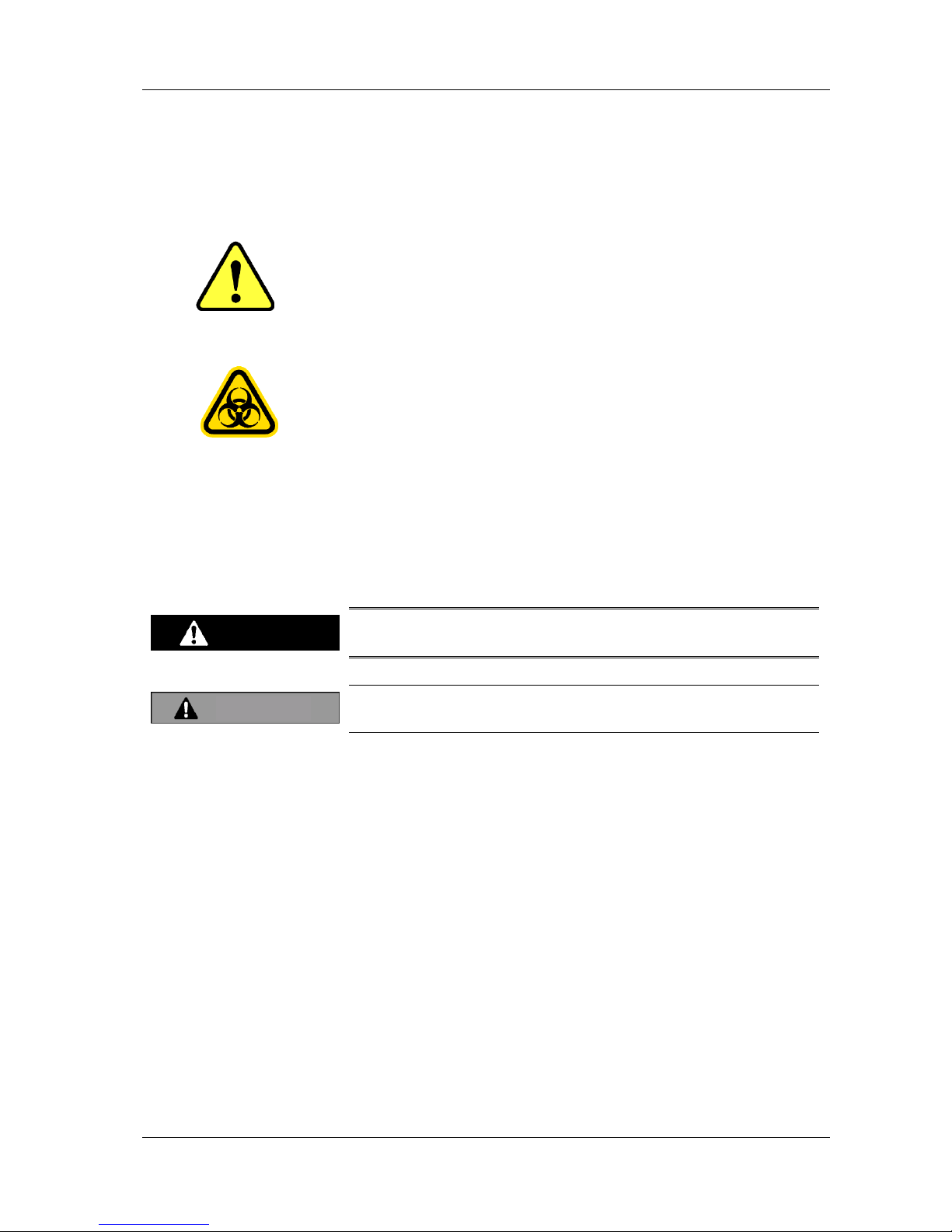
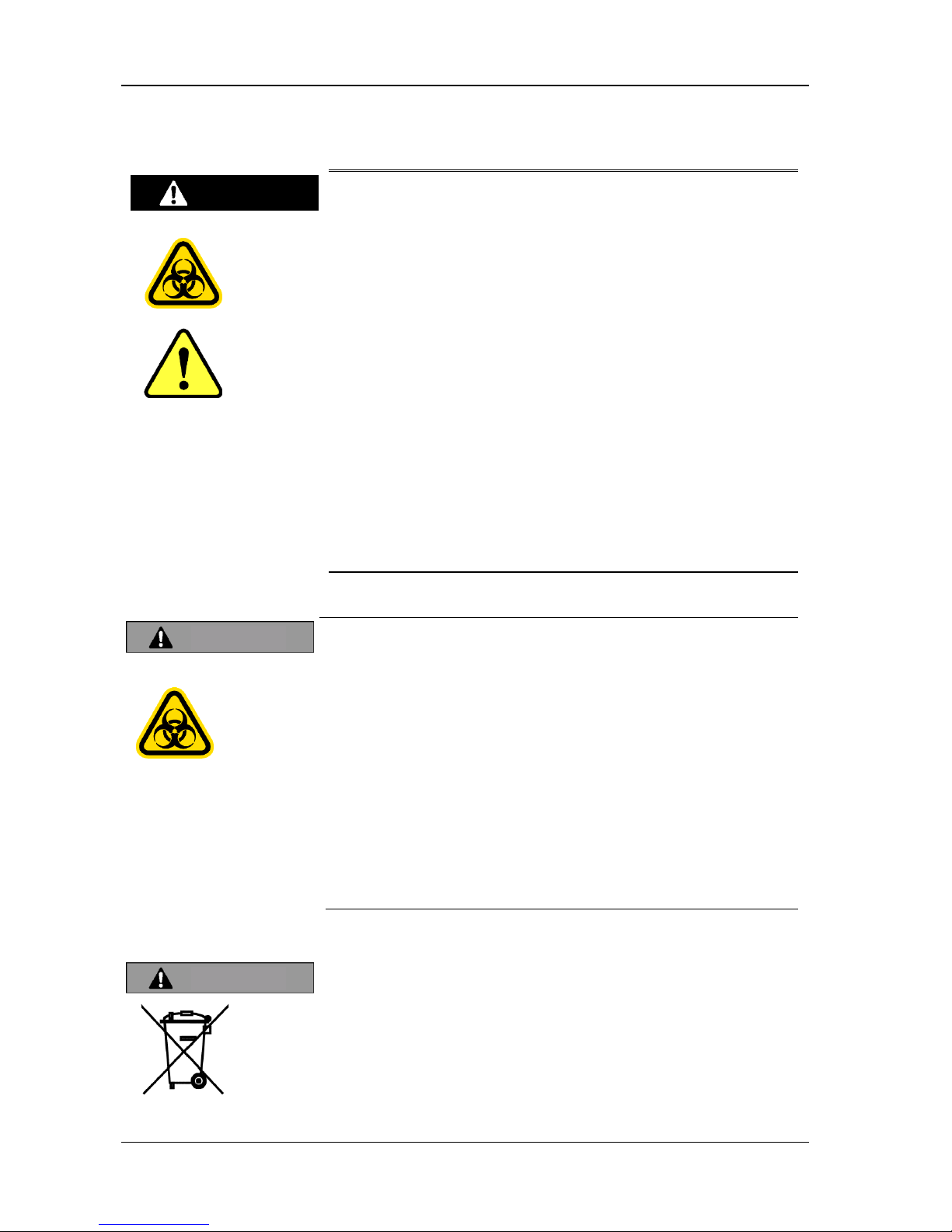
2.1 Explanation about Alert Symbols
The alert symbol on the left is used on this Instrument and in this
Manual to indicate potential dangers. This symbol represents
unspecified general risks and provides warnings and cautions. The
precautions stated after this symbol should be notified for safety
reasons.
The alert symbol on the left used on the Instrument and in this Manual
indicates potential dangers. This symbol represents infectious risk and
provides warnings and cautions. The precautions stated after this
symbol should be notified for safety reasons.
2.2 Explanation of Warnings
Two types of warning legends are used on the Instrument and in this
Manual. These warnings are used separately as described below to
indicate the degree (magnitude) of personal injury and property damage
which could occur.
This signal and the legend is used in situations in which
incorrect handling could result in serious injury to the user.
This signal and the legend is used in situations in which incorrect
handling could result in minor injury to the user.
Classifications and categories of damage and injury severity
The degrees of damage and injury used above are classified as follows:
Severe Injury: Loss of vision, wounds, burns (high or low
temperature), electric shock, bone fracture, poisoning,
infection etc. resulting in permanent after effects, or
requiring medical care involving hospitalization or
prolonged outpatient treatment.
Light injury: Injury other than the above, not requiring medical care
involving hospitalization or prolonged outpatient
treatment.
Warning
Caution
HM-JACKarc Operation Manual
Safety Precautions
2 - 2 Rev.4
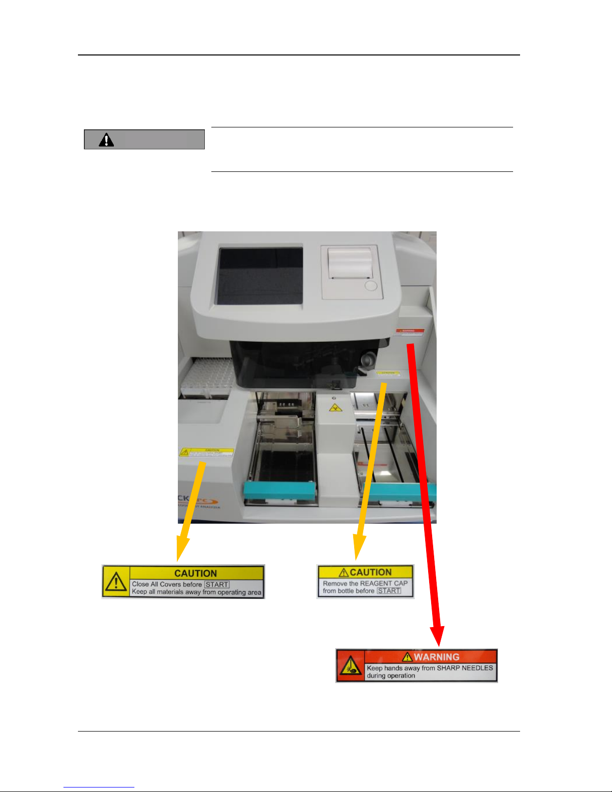
2.3 Explanation of Warning Labels Affixed to
the Analyzer
Make sure that warning labels are legible at all times. If a label peels
off, contact local distributor immediately.
Never peel warning labels off or modify them.
The warning labels shown below are affixed to warn operators of
potential hazards.
Caution

HM-JACKarc Operation Manual
Safety Precautions
2 - 3 Rev.4
2.4 Safety Precautions for Operators
Before using this Instrument, make sure that the Instrument
was installed by authorized personnel.
If the Instrument is not installed correctly, it could break down
or cause fire, electric shock or injury.
Check the following points before starting operation. These
checks are necessary in order to prevent accidents and injuries.
the warning labels are legible
the ground connection is fully secured
A broken power cable could result in electric shock, fire, and
short circuit. Observe the following points.
the cable is not twisted
the cable is not caught by pressure between the Instrument
and the wall.
the cable is not bent too tight
nothing is put on the cable
the cable is not tied in a bundle
the cable is not modified
the cable is kept away from any heater.
the plug itself, not the cable, is gripped when unplugging the
cable
Dust accumulated on the power plug can start a fire. Check the
plug regularly and remove dust.
Insert the power plug firmly into the socket. Poor contact could
cause overheating, burn injuries and fires.
Do not get the power cable or plug wet, or electrical shock and
short circuit may result.
Never touch the power plug with wet hands, or electric shock
may result.
Using the power cable plug (plugging it in and unplugging it) to
turn the power on and off may cause the plug to overheat.
Always use the power switch (or the Main Breaker).
Warning
HM-JACKarc Operation Manual
Safety Precautions
2 - 4 Rev.4
Only use consumables and replacement parts (including
screws) that are specified by Kyowa Medex Co., Ltd.
Before cleaning the Instrument, turn the power off and be
sure to remove the power plug from the socket.
In the event of any malfunction of the Instrument, turn the
power switch off immediately and remove the power plug
from the socket. Leaving faults unattended can cause
accidents and fires.
Do not turn the power switch off and on repeatedly.
The Mixing Spatula, Sample Pipette and Reagent Pipette
attached to the injection assembly are sharp and could
cause injury.
The ends of the Mixing Spatula, Sample Pipette and Reagent
Pipette attached to the injection assembly come into direct
contact with Samples (stool samples) and Reagent. Incorrect
handling of those parts could cause infection with
pathogens or poisoning with Reagent. Wear medical rubber
gloves while working, and take extra care to avoid infection.
Warning
HM-JACKarc Operation Manual
Safety Precautions
2 - 5 Rev.4
2.5 Safety Precautions for Maintenance
Do not modify the Instrument without permission. Modification
could cause unexpected hazards.
Use consumables and replacement parts (including screws)
only specified by Kyowa Medex Co., Ltd.
Before servicing the Instrument or removing any of its parts
(fixing faults, replacing parts, inspecting, repairing, etc.), turn
the power switch off and be sure to disconnect the power plug
from the socket to avoid getting electric shock.
When disconnecting the power plug from the socket, always
grip and pull on the plug itself, not on the cable.
Use fuses of the only specified type. Use of non-specified fuses
could cause the Instrument to malfunction or, in some cases,
start a fire.
Using the power cable plug (plugging it in and unplugging it) to
turn the power on and off may cause the plug to overheat.
Always use the power switch (or the Main Breaker).
This Instrument weighs approximately 56 kg. Handle it with
extra care when moving. Note that moving the Instrument
should be done by two or more people.
The ends of the Mixing Spatula, Sample Pipette and Reagent
Pipette attached to the injection assembly are sharp and could
cause injury.
The ends of the Mixing Spatula, Sample Pipette and Reagent
Pipette attached to the injection assembly come into direct
contact with Samples (stool samples) and Reagents, so
incorrect handling of those parts could cause infection with
pathogens or poisoning with reagents. Wear medical rubber
gloves while working, and take extra care to avoid infection.
Warning
HM-JACKarc Operation Manual
Safety Precautions
2 - 6 Rev.4
2.6 Waste Materials Precautions
Samples could be contaminated with pathogens etc., so take
extra care to avoid infection when handling them, by wearing
medical rubber gloves etc.
Before handling sample containers, reagents and buffer, read
and understand the Instructions for Use. Handle them with care
to avoid accidents.
Any Mixing Spatula, Sample Pipette and Reagent Pipette which
has been detached or removed is sharp and dangerous. Handle
them with extra care.
The ends of the Mixing Spatula, Sample Pipette and Reagent
Pipette attached to the injection assembly come into direct
contact with samples (stool samples) and reagents. Incorrect
handling of those parts could cause infection with pathogens or
poisoning with reagents. Wear medical rubber gloves at all
times while working, and take extra care to avoid infection.
Here below is a list of Waste materials generated by regular analysis.
They should be handled as medical waste and disposed of by a
specialist contractor.
Liquid waste
Used cells
Reagents and reagent bottles
Buffer and buffer fluid bottles
Used stool sample containers
Hemoglobin standards before and after preparation
Hemoglobin standard containers
Used sample cups
Control samples before and after preparation
Control sample containers
The Instrument contains lithium battery. The local restriction or WEEE
should be applied when battery is wasted. Ask for local distributor for
more information.
Warning
Caution
Caution

HM-JACKarc Operation Manual
Safety Precautions
2 - 7 Rev.4
2.7 Instrument Safety Device
Overcurrent Protection
2 or more ampere of current (input voltage 220v) will be interrupted
immediately by internal breaker and the power will be shut down.
Transformer Secondary Fuses
A fuse is installed to protect Control PCBs (Main PCB, Power PCB) from
overcurrent.
Thetransformer is protected from overheating by a thermal fuse.
A fuse is installed to protect the lamp from overcurrent.
Outer Cover Opening Check Sensor
If the outer cover is open, the Analyzer does not start motion. If the outer
cover is opened while the Analyzer is in motion, an error occurs and the
Analyzer will stop sampling. There are 2 switches to secure the function.
2.8 Noise Level of the Analyzer
The maximum noise level is 70db.
2.9 Note for Supplied Water and Detergent
Temperature of supplied water
The temperature of supplied water for this Instrument should be in
20-30 ℃ . Lower temperature of water may cause malfunction of
instrument wash, and higher one may damage the tubing and lead to
leakage of water.
Amount of use of Detergent
The amount of use of Detergent (water include 0.1% of detergent) is
approximately 4.5mL per a test. It is also used in priming and wash. It is
necessary to keep enough amount of prepared Detergent during the run.

HM-JACKarc Operation Manual
Outline of Instrument
3 - 1 Rev.4
3 Outline of Analyzer
3.1 Characteristics of the Analyzer
3.1.1 Outline
This Analyzer measures the amount of human hemoglobin present in
a stool sample.
Compact and light analyzer designed for installation in a small space.
Barcode reading input is applied to register Sample ID, Calibration
Master Curve and Calibrator Information to make the operation easier
for operators.
A two-point calibration method is adopted to simplify the measurement
operation.
The measurement method is Latex Agglutination, which is quick and
achieves superior sensitivity.
Superior detection sensitivity realizes smaller volume of stool sample
and less smell.
The sample loading capacity of the Analyzer is 80.
Reaction Cells are replaced after use automatically.
The Sample Collection Picker achieves superior stability for human
hemoglobin, reduces the decline in the amount of human hemoglobin
and enables more accurate measurement.
Analysis results can be checked on the screen and printout. Also,
connection to a host computer enables data to be exported.

HM-JACKarc Operation Manual
Outline of Instrument
3 - 2 Rev.4
3.1.2 Principles of Operation
The Reagent Pipette aspirates the Latex Reagent, which then move to a
Cell on the Reaction Table, where it is dispensed together with the Buffer.
Next, the Reaction Table Rotates and the Cell containing the Reagent
moves to the sampling position. The Sample Pipette aspirates a Sample,
which is then dispensed to the Cell. The Mixing Spatula then turns
counterclockwise to mix the Reagent and the Sample together.
The Cell containing the Reagent and the Sample moves to the detection
position after a period of time set under the measurement conditions, and
the first photometric measurement (ISTT1) is performed. After another set
period of time, the second photometric measurement (ISTT2) is
performed.
The amount of change in the Integrating Sphere Turbidity of the two
photometric measurements (ΔIST=IST
T2
-ISTT1) is calculated by the
computer according to the calibration curve to output the measurement
result.
This series of actions is repeated to measure all samples placed in the
sample rack.
IST: Integrating Sphere Turbidity
HM-JACKarc Operation Manual
Outline of Instrument
3 - 3 Rev.4
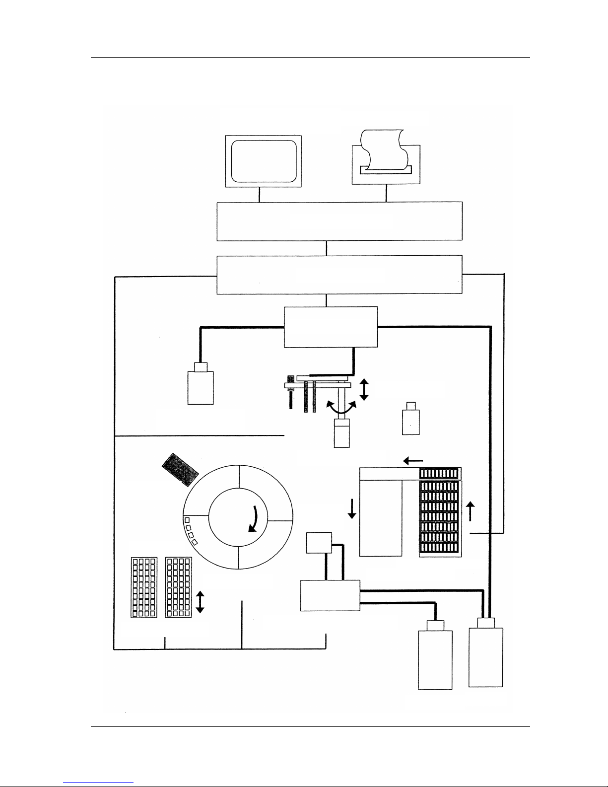
Operating Principle Diagram (Block Diagram)
Operation and Display Panel
(backlight color LCD panel)
Printer Paper
Microcomputer
Interface
Injector
Buffer Fluid
Latex Reagent
Injection Arm
Wash
Station
Turbidity Meter
Cell Cassette
Reaction Table
Cell Transportation
Supply and Waste Water Pump
Waste Liquid
Detergent
Sample Transportation
Sample Rack
HM-JACKarc Operation Manual
Outline of Instrument
3 - 4 Rev.4
3.1.3 Stool Samplers and Reagents
This Analyzer uses EXTEL HEMO・ AUTO HS as the measurement
reagent, together with the HEMO・ AUTO MC Collection Picker and
achieves:
Major improvement in reproducibility in range close to the cut-off
Large improvement in low-value reproducibility
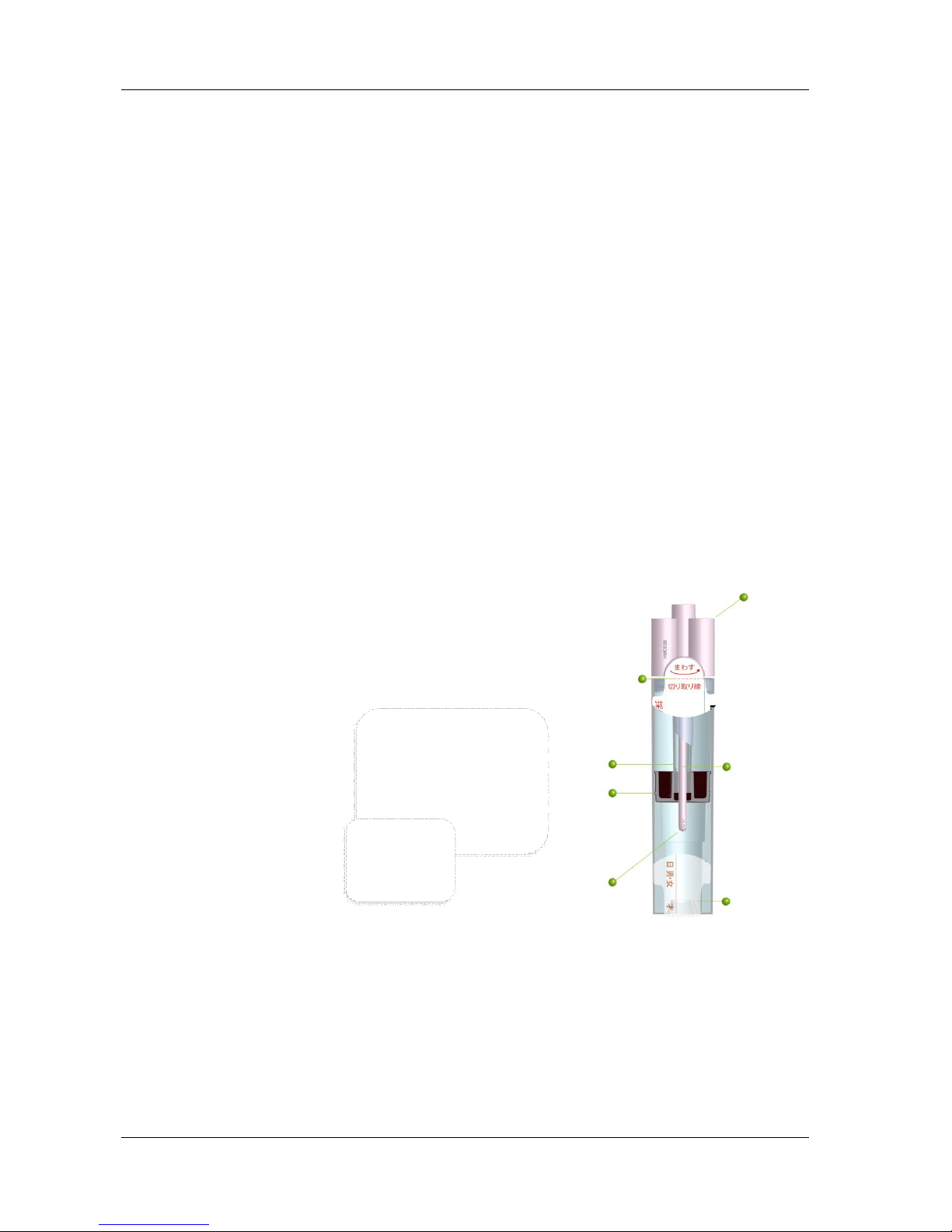
By developing the HEMO・AUTO MC Collection Picker (patent applied
for), with the optimum reagent concentration to make the most of the
characteristics of the integrating sphere photometer, we have
achieved:
Optimization of the volume of stool sample by the two-step rotary
scraping method
Adoption of hexagonal stool sampling holes that improves both stool
holding and solubility
One-way collection of excess stool and easy check of whether stool
has been sampled
Time-saving by adopting integrated multifunction seals.
The features mentioned above enhance operability, accelerate
processing speed, and improves reproducibility of this Instrument.
Piercer
Blending
Section
Stool
Collection
Rod
Tip of stool
collection rod
Separator
Stool
Collector
HEMO・AUTO
MC
Collection Picker
HM-JACKarc Operation Manual
Outline of Instrument
3 - 5 Rev.4
3.2 Part Names
The names of the parts of this Instrument are as follows:
Top
Right side
Display
Cell Cassette
(40 Reaction Cellsx2 (L, R))
Outer Cover
Sample Tray (eject)
Sample Tray (load)
Printer
Injection Arm
Handheld Scanner
Reaction Table
(Reaction Cell)
Integrating Sphere
Turbidity Meter
Buffer Reagent Cover
Latex
Buffer bottle
Inside the Cover
USB Slot
HM-JACKarc Operation Manual
Outline of Instrument
3 - 6 Rev.4
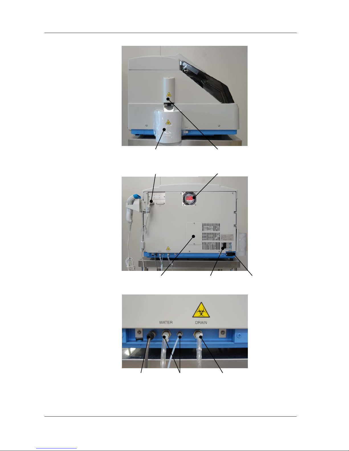
Left side
Back
Cell Waste Box
Cell Hand Cover
Handheld Scanner Connector
Cooling Fan
Lamp Replacement Panel
Breaker Switch
Power Cable Plug
Detergent sensor
Detergent tube
Waste tube
Connectors

HM-JACKarc Operation Manual
Outline of Instrument
3 - 7 Rev.4
3.3 Materials Required
Here below is the list of required materials other than parts provided with
the Analyzer.
EXTEL HEMO・AUTO HS Latex
EXTEL HEMO・AUTO Buffer
EXTEL HEMO・AUTO HS Calibrator
EXTEL HEMO・AUTO HS Control
EXTEL HEMO・AUTO MC Collection Picker
EXTEL HEMO・AUTO Reaction Cell
Please contact your local supplier to order the products.
HM-JACKarc Operation Manual
Functions of Each Screen
4 - 1 Rev.4
4 Functions of Each Screen
4.1 Display and Operation Screens
The names and functions of the various icons on the operation screen
are as follows:
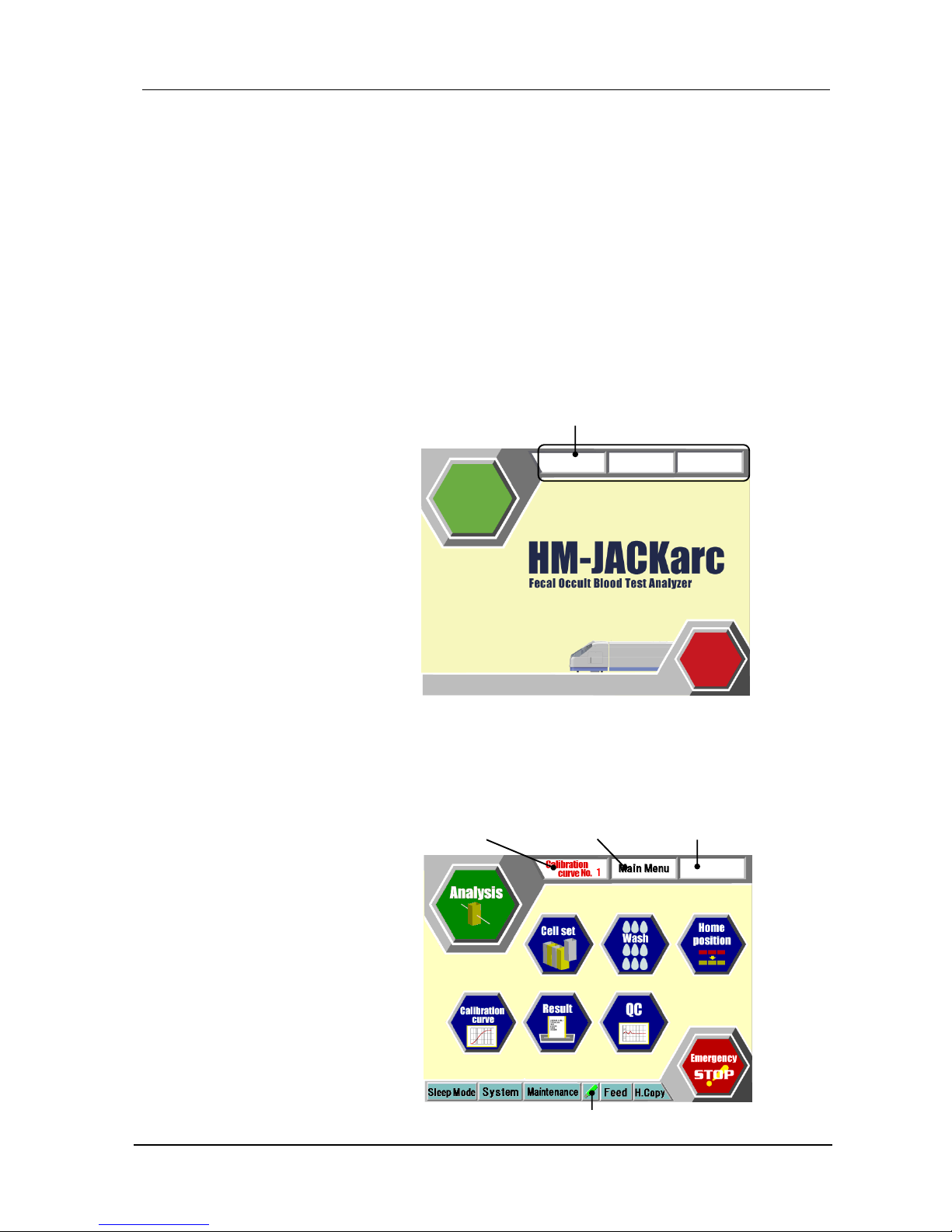
4.1.1 Startup screen (Initial Screen)
This screen is displayed after the power is turned on.
Touch the screen to move to the Main Menu screen.
4.1.2 Main Menu screen
This screen is main screen to start operations. Touching any RETURN
key on each screen several times finally returns to this screen.
Applied Calibration
curve Number
Name of current
screen
Supplementary name of
current screen
Current versions of programs
(Main, Control and Detect)
USB Mark (if connected)

HM-JACKarc Operation Manual
Functions of Each Screen
4 - 2 Rev.4
Analysis icon
Touch this icon to go to Order screen to start preparations for
measurement. See 4.1.3 Order for details.
Cell Set icon
Touch this icon to move to the Cell Set screen to display the status for
Cells on the Reaction Table. See 4.1.5 “Cell Set” for details.
Wash icon
Touch this icon to run a wash or prime the system.
After the initialization of the Injection Arm, the system performs priming to
fill the tube between the Sample Pipette and the Sample Syringe with
Detergent, and the tube between the Reagent Pipette and the Reagent
Syringe with the Buffer. Then the Analyzer stops.
When the Buffer or Detergent have been replaced or replenished, touch
this Wash icon to run a wash/prime cycle.
Home position icon
Touch this icon to return all moving parts to their home positions.
Calibration curve icon
Touch this icon to go to Calibration screen. Master Curve/Calibrator
registration are available from the screen.
See 4.1.5 “Calibration” for details.
Results icon
Touch this icon to display analysis results. The Results screen can be
used to display or print results, or send them to the host computer. To
display real time results, touch this icon during operation.
See 4.1.7 “Result” for details.
QC icon
Touch this icon to display analysis results for quality control.
X-R control diagrams and histograms are available from the menu.
See 4.1.8 QC for details.
Emergency STOP icon
Touch this icon to stop all movement immediately. Using this function
wastes all the processing measurement.
For actions after an emergency stop, refer to page 5-28 “Actions for
Recovery from Emergency STOP”.
Applied Calibration curve Number
The currently applied Calibration curve Number (No. 1 in this case) is
displayed.

HM-JACKarc Operation Manual
Functions of Each Screen
4 - 3 Rev.4
Name of current screen
The name of the current screen is displayed.
Supplementary name of current screen
The current operation status is displayed.
Sleep Mode button
Touch this button to go to screen to set up the date and time of the next
startup. See “Set Sleep Mode” on page 5-24 for details.
System button
From the menu various system parameters can be modified, but it is not
allowed to modify the parameters without permission.
Maintenance button
Touch this button to go to the Maintenance Menu screen.
Refer to the Service Manual for details.
USB Mark(if connected)
When a USB is inserted to the USB slot and recognized by the system,
the mark on the left appears. Touching this icon allows the USB stick to
be removed safely.
Feed button
Touch this icon to feed the printer paper.
H.Copy button
Touch this icon to print out the hardcopy of the screen.

HM-JACKarc Operation Manual
Functions of Each Screen
4 - 4 Rev.4
4.1.3 Order
When the Analysis icon is touched, Order screen appears. Analysis and
calibration can be started only from this screen.
Start Icon
Touch this icon to start measurement. See 4.1.4 “Analysis” for details.
Main Menu icon
Touch this icon to go back to the Main Menu screen.
Sample Stop icon
Touch this icon to stop sampling. Ongoing measurement still goes on
after sampling stop and will complete.
Home Position icon
Touch this icon to return all moving parts to their home positions.
Sample Status field
After starting measurement Sample Status will be displayed in this field.
See “Sample Status field” on page 4-7
ID column
(Not in Use)
Attribute field
(Not in Use)
Applied Calibration
curve Number
Name of current
screen
Sample Status field
Attribute field
USB Mark (if connected)
Supplementary name of
current screen

HM-JACKarc Operation Manual
Functions of Each Screen
4 - 5 Rev.4
Barcode ID column
During the measurement, currently read sample barcode ID is displayed
in this column.
Latex column
Touch this column to input the volume of Latex Reagent. Available test
with the Latex Vial set to the Instrument is displayed and counted down
accordingly during measurement. See “Setting Reagent volume” on page
5 - 6 for details.
■Time Remained column
Estimated finish time is displayed.
Emergency Stop icon
Touch this icon to stop all movement immediately. Using this function
wastes all the processing measurement.
For actions after an emergency stop, refer to page 5-28 “Actions for
Recovery from Emergency STOP”.
Applied Calibration curve Number
The currently applied Calibration curve Number (No. 1 in this case) is
displayed.
Name of current screen
The name of the current screen is displayed.
Supplementary name of current screen
The current operation status is displayed.
System button
From the menu various system parameters can be modified, but it is not
allowed to modify the parameters without permission.
All Clear button
Touch this button to clear all the information displayed in Sample Status
field.
USB Mark (if connected)
When a USB is inserted to the USB slot and recognized by the system,
the mark on the left appears. Touching this icon allows the USB stick to
be removed safely.

HM-JACKarc Operation Manual
Functions of Each Screen
4 - 6 Rev.4
Feed button
Touch this icon to feed the printer paper.
H.Copy
Touch this icon to print out the hardcopy of the screen.

HM-JACKarc Operation Manual
Functions of Each Screen
4 - 7 Rev.4
4.1.4 Analysis
During the measurement, the screen below is displayed.
Sample stop icon
Touch this icon to stop further sampling. Ongoing measurement still goes
on after sampling stop and will complete. Touch Start icon to restart the
measurement again.
Main Menu icon
Touch this icon to go back the Main Menu screen.
■Rack Monitor
・Sampling
The sample rack Number and position Number being sampled at the
moment is displayed.
R: ID of the Rack is displayed
The position being sampled now is colored green.
・Sampling End
R: ID of ejected Rack is displayed.
Status and
operation
message
Applied calibration
curve number
Name of current
screen
Supplementary name of
current screen
Sample Status
field
Rack monitor
USB Mark (if connected)

HM-JACKarc Operation Manual
Functions of Each Screen
4 - 8 Rev.4
Sample Status field
The status of each sample is displayed.
・Sel.:(Not in use)
・No.:Sample No.: 1-320
・Pos.:Attribute or Position Number
STD1 : Calibrator 1
STD2 : Calibrator 2
CTLL : Control L
CTLH : Control H
Cup : Sample Cup(as optional)
Samples : rrr-pp
rrr: Rack No. 001-999 (rack barcode)
pp: Position No. within rack No. 1-10
・ID CODE
When Sample barcode is enabled, Sample barcode for each
sample is displayed. When Sample barcode is disabled, User
ID is displayed.
・Av.:Attribute or repetition number is displayed.
Calibrator 1 and 2 = Average number of Calibration
(Set as an item parameter: 1-3)
Control L = Repetition number of Control L
(Set as an item parameter: 1-3)
Control H = Repetition number of Control H
(Set as an item parameter: 1-3)
Cup = Repetition number of Sample Cup(as optional)
(Set as an item parameter: 1-3)
Patient Samples (one-day method) = 1
Patient Samples (two-day method) = 1 (1st day), 2 (2nd day)
・Data:Results of the Sample is displayed.
・Alarm:If an event occurred for the Sample, a flag is displayed in this
column. Refer to Error List for details of the code.
■Status and Operation Message
The status of the analyzer and supplementary message is displayed
timely in this area during operation.
Latex column
Touch this column to input the volume of Latex Reagent. Available test
with the Latex Vial set to the Instrument is displayed and counted down
accordingly. See “Setting Reagent volume” on page 5 - 6 for details.
■Analysis end time
Estimated remaining time of the run is displayed in this column. This
column is not in use after finishing the run.

HM-JACKarc Operation Manual
Functions of Each Screen
4 - 9 Rev.4
Emergency Stop icon
Touch this icon to stop all movement immediately. Using this function
wastes all the processing measurement.
For actions after an emergency stop, refer to 5.1 “Actions for Recovery
from Emergency STOP”.
Applied calibration curve Number
The currently applied calibration curve (No. 1 in this case) is displayed
Name of current screen
The name of the current screen is displayed.
Supplementary name of current screen
The current operation status is displayed.
System button
Various parameters can be modified from this menu, but it is allowed to
enter this menu only when it is necessary to change input data for
Calibrator manually. Refer to ****** for details.
To Order button
Touch this button to start measurement after finishing previous one. Start
icon will appear.
USB Mark (if connected)
When a USB is inserted to the USB slot and recognized by the system,
mark on the left appears. Touching this icon allows the USB stick
removed safely.
Feed button
Touch this icon to feed the printer paper.
H.Copy button
Touch this icon to print out the hardcopy.

HM-JACKarc Operation Manual
Functions of Each Screen
4 - 10 Rev.4
4.1.5 Cell Set
This is the screen to control the Cells. It is not required to take care of
Cells as long as the Cassettes replaced as required. If required, touch
Cell Set icon on the Main Menu to go to Cell Set screen.
Main Menu icon
Touch this icon to go back the Main Menu screen.
Home position icon
Touch this icon to return all moving parts to their home positions.
■Position Status field
The status of each position of the Reaction Table is displayed in five
abbreviations as below.
・OK : A Cell is set and available
・MS : Measurement is ongoing
・NG : The position is checked but not available
・?? : The position is not checked yet
・( Blanc): No Cell is present
■All Changes icon
Touch this icon to replace all cells on the Reaction Table.
■Selective Change icon
Touch this icon to replace unavailable cells on the Reaction Table
recognized by the Analyzer.
Applied calibration
curve number
Name of current
screen
Supplementary name of
current screen
USB Mark (if connected)
Position Status field

HM-JACKarc Operation Manual
Functions of Each Screen
4 - 11 Rev.4
■All OK icon
Touch this icon to change the status of all Reaction Table positions to OK.
■Cell Cassette icon
Touch this icon to go to the Cell Cassette screen.
Cell Cassette screen
・Cell Cassette Map
This map indicates presence of cells (1-40) on the cassettes (R and L) on
the Analyzer.
・White blocks : A Cell is present.
・Dark gray blocks : No Cell is present.
・Blue Block : The position will be picked up first. It can be
changed with touching another one.
・Start Position
The position picked up first is displayed.
・Cell Set icon
Touch this icon to go back to Cell Set screen.
Cell Cassette Map

HM-JACKarc Operation Manual
Functions of Each Screen
4 - 12 Rev.4
4.1.6 Calibration
■No1./No2. Tub
The Analyzer can hold two Calibration data. Touch one of them to choose
Calibration data to view.
■Date of Master Curve registration
The date of Master Curve registration is displayed.
■Master Curve data field
Each I.S.T of registered Master Curve is displayed in I.S.T column. Backfit
will be displayed after calibration completed.
■Lot information field
Lot information of Master Curve and Calibrator is displayed.
■Master button
Touch this button to refer to the data input with registration of Barcodes or
to input data manually. Refer to ****** for procedure for manual input of the
data.
■Curve button
Touch this button to view the calibrated Master Curve.
■Barcode button
Touch this button to move to Barcode Registration mode. See 5.2.8
“Registration of Master Curve” for details.
Applied calibration
curve number
USB Mark (if connected)
Name of current
screen
No1/No2 Tub
Date of Master Curve
registration
Master Curve data
field
Lot information
field

HM-JACKarc Operation Manual
Functions of Each Screen
4 - 13 Rev.4
■Curve 1⇔2 button
Touch this button to change Calibration data to apply. Confirmation window
will appear after touching this button. This is the only way to change
Applied Calibration between 1 and 2.
■RETURN button
Touch this button to go back to Main Menu.

HM-JACKarc Operation Manual
Functions of Each Screen
4 - 14 Rev.4
4.1.7 Result
■File name and Number of Data
The name of the file and number of Data inside the file is displayed.
■Results field
Below information is shown
・Avail : When this column is touched, X mark will be displayed and the
data of the row will be excluded from the target of Execution.
・Sel. : First, touch one of the commands at the bottom of the screen
to execute. Then touch this column to select as the target. ✔
mark will be displayed.
・No. : Sample number
・Pos : Rack ID and position number
・User ID : The number that the system applies to every sample following
a configuration in User Parameter.
・Barcode : Barcode of the Sample. Touch this area to view Reaction
Data. See 4.1.6 Reaction Data for reference.
・Av. : Number of repetition of Calibrator and Control
・Data : Result of the Sample(ng/mL)
・+/- : Qualitative Result
・Mark : Flag or Error Code
■File
Touch this button to display File List. Touch one of the files in the list to
display the detailed data.
Applied calibration
curve number
Name of current
screen
USB Mark (if connected)
Results field
File name and
Number of data

HM-JACKarc Operation Manual
Functions of Each Screen
4 - 15 Rev.4
■Output button
Touch this button to output data. When this button is touched, Host and
Print button will appear. Touch one of them, select target result(s) with
touching Sel column and then touch Execute button.
・Host : Send the selected Result(s) to the Host Computer
・Print : Print out the selected Result(s)
■Calc button
Touch this button to calculate results again. When this button is touched,
two buttons will appear.
・Recalc :This button is effective only when the calibration data is revised.
The data can be calculated based on the new calibration data.
・CV : CV can be calculated from selected results. Touch sel column of
target data to select and touch Execute button. The Calculated
CV can be printed out afterwards. (CV: Coefficient of Variation)
■Avail button
(Not for Use)
■RETURN button
Touch this button to go back to the Main Menu.

HM-JACKarc Operation Manual
Functions of Each Screen
4 - 16 Rev.4
4.1.8 Reaction Data
■Measurement Information field
Information about Sample and Reagent is displayed.
■Reaction Data field
Reaction Data (I.S.T of each point) is displayed.
■Reaction Curve field
Reaction Curve of is displayed.
■Lot Info. button
Reaction Data field will be changed
to the information on the right.
■PREV. /NEXT button
Touch these buttons to view previous/next result.
Measurement
Information field
Reaction Data
field
Reaction Curve
field

HM-JACKarc Operation Manual
Functions of Each Screen
4 - 17 Rev.4
4.1.9 QC
QC check functions are available from this screen. Touch one of menus
to enter the function.
CQ Menu screen
■Control X-bar Chart
X-bar chart is calculated from the control data and displayed. The
maximum number of calculated data is 31 from the start date. The data
plotted on the chart are average of each control result of a run.
・Date button : To direct the start date of the chart, touch these
buttons to display Numeric keys. Enter the start
date(yyyy/mm/dd) and touch Enter key.
・Information field : Statistic data are displayed.
・Chart : The Chart of each (Low/High) control
Date button
Information
field
Chart

HM-JACKarc Operation Manual
Functions of Each Screen
4 - 18 Rev.4
・Low List button : Touch this button to exclude certain data from
the chart. List of the data will be shown, then
touch Avail and mark with X to exclude from the
Low chart.
・High List button : Touch this button to exclude certain data from
the chart. List of the data will be shown, then
touch Avail and mark with X to exclude from the
High chart.
■Histogram Result List
When the Histogram button is touched, the screen below is displayed.
Choose All, Today or touch Sel to target for execution.
・Sel column : Target Data with ✔ mark
・All button : Target All the data
・Today button : Target Data of current date
・Graph button : Tabulate the Graph including selected data
■Histogram
・Qualitative button : Show the Qualitative(+/-) tabulation

HM-JACKarc Operation Manual
Functions of Each Screen
4 - 19 Rev.4
4.2 System Menu Screen
The System Menu is displayed when System button is touched. These
menus are for service personnel.

HM-JACKarc Operation Manual
Functions of Each Screen
4 - 20 Rev.4
4.3 Maintenance Menu Screen
The Maintenance Menu screen is displayed when the Maintenance button
is touched.
■Unit Control
Each moving unit can be operated separately from this menu. Also, some
configuration can be adjusted and the status of sensors can be checked.
This function is for service use.
■DETECT TEST
When this button is touched, DETECT screen is displayed. The scattering
light and transmitted light can be observed on the screen. This function is
for service use.
■Error History
Error History display can be seen from this menu.
■Maintenance
Touch this button to go to the Maintenance menu. This function is for
service use.

HM-JACKarc Operation Manual
Analysis Operations
5 - 1 Rev.4
5 Analysis Operation
5.1 Flow of Analysis Operation
Routine analysis operation follows the process described below.
1. Turn on the Analyzer (and Log in optional)
Turn the Analyzer on about an hour before the start of analysis, to allow
it to warm up.
Use of Sleep Mode can avoid the need for this warming-up period.
2. Prepare Detergent in the Wash Tank
3. Prepare the Waste Tank and Cell Dust Box
Empty the Waste Tank / Cell Dust Box if necessary.
4. Prepare the Reagent
Let the Latex Reagent warm to room temperature before use.
Set the reagent volume on the Sample Order screen, if necessary.
5. Prepare the Buffer
Let the Buffer warm to room temperature before use.
6. Prepare the Reaction Cells
If required, use the Cell Set screen to set the starting position for
picking up the cells and replacing used cells.
7. Prepare for calibration
When Latex lot is changed, register Master Curve. When the Calibrator
lot is changed, register barcodes of Calibrator Card.
8. Prepare the Calibrators (S1, S2)
If calibration is necessary, prepare the Calibrators.
9. Prepare the Controls (CL, CH)
10. Prepare the Patient Samples
Set the Patient Samples in Collection Picker or Sample Cup in the
Sample Racks.
10. Load Racks
Load Racks equipped with required materials.
11. Analysis
12. Completing Analysis

HM-JACKarc Operation Manual
Analysis Operations
5 - 2 Rev.4
5.2 Preparations for Starting Analysis
5.2.1 Turning on the Analyzer
There are two different ways to turn on the Analyzer.
Turning on manually
Before turning the power on, check that the power plug is
correctly inserted into the socket.
If the power plug is not connected correctly and securely, there
is the risk of overheating leading to fire and or electric shock.
It takes approximately one hour for the instrument to warm up and to be
ready for analysis after power is turned on. Turn it on in advance of
starting analysis.
Switch on the POWER on the left side of the Main Unit. The Start Up
screen will be displayed and touch anywhere of screen to go to Main
Menu.
Power switch (On)
Turning on automatically (from Sleep Mode)
When Sleep Mode is set after previous operation, the Analyzer starts up
automatically and the Start Up screen is displayed. Touch anywhere of
screen to return to Main Menu.
Warning

HM-JACKarc Operation Manual
Analysis Operations
5 - 3 Rev.4
Logging in to the Analyzer (as option)
Log in function is an option. For the configuration, contact local
distributor.
When Log in function is enabled, below screen will appear instead of
the Start Up screen after turning on.
To log in, touch each USER and PASS column. Then input User ID and
Password corresponding to the configuration from displayed key board.
Note that the input is case sensitive.
Current versions of programs
(Main, Control and Detect)
USER column
PASS column

HM-JACKarc Operation Manual
Analysis Operations
5 - 4 Rev.4
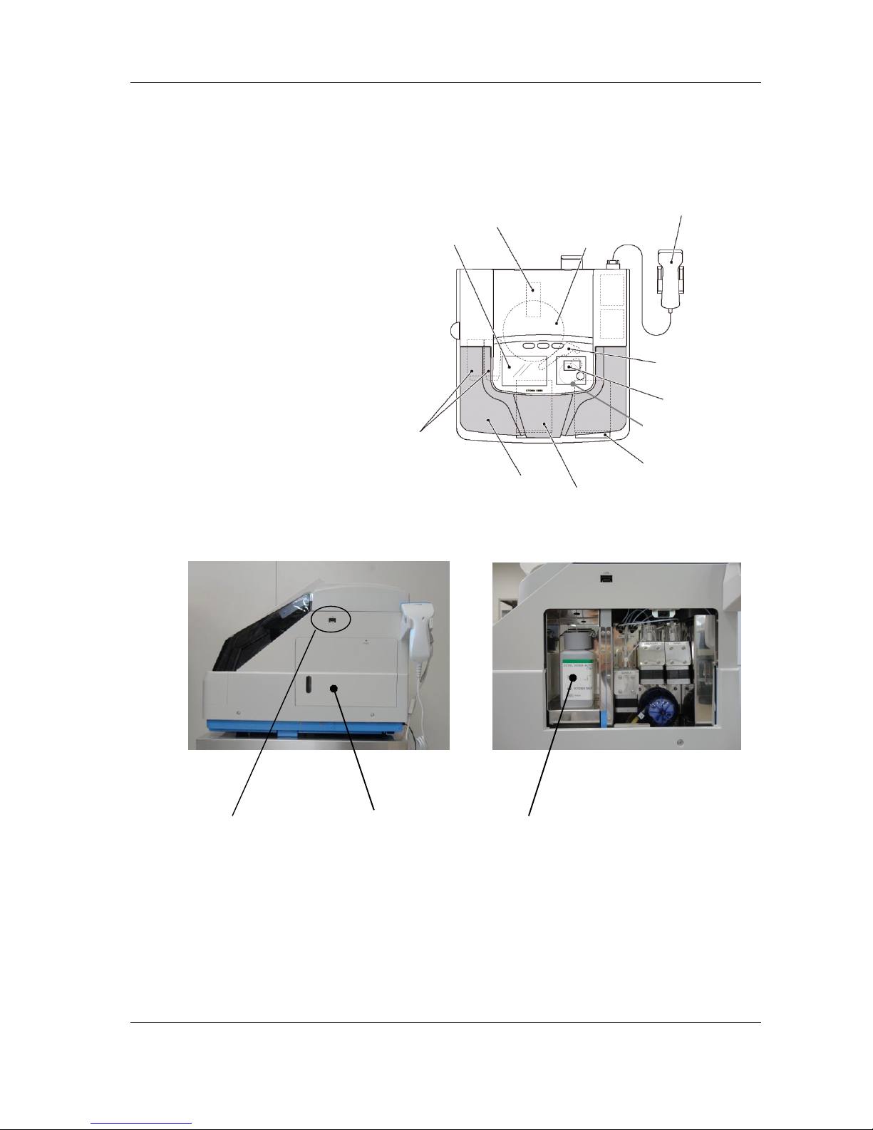
5.2.2 Preparing Detergent in the Wash Tank
The Detergent should be a 1:1000 dilution of Auto Detergent H.
When preparing the Wash solution, use purified water or deionized
water. Do not use water mixed with foreign substances or
contaminated with chemicals or tap water. Accurate analysis results
may not be obtained if the detergent is not prepared correctly.
When pouring detergent into the Wash Tank, take care to avoid
touching the tubes that enter the Wash Tank with your bare hands.
This Analyzer will stop sampling when the level of the Wash solution
becomes lower than a certain level. In that case, refill Wash solution
and touch Start on the screen to start sampling.
Caution
Medical rubber gloves
Wash solution (5L)
Wash Tank
Wash Tank

HM-JACKarc Operation Manual
Analysis Operations
5 - 5 Rev.4
5.2.3 Preparing the Waste Tank
This Analyzer will not stop when the Waste Tank becomes full. Be
sure to empty the Tank before starting analysis.
Waste should be handled as medical waste and disposed of by
recognized laboratory practices.
Waste in the Waste tank should be discarded.
Caution

HM-JACKarc Operation Manual
Analysis Operations
5 - 6 Rev.4
Reagent bottle
5.2.4 Preparing the Reagent
Set the bottle of EXTEL HEMOAUTO・HS Latex (referred to below as
"Reagent") in the Main Unit.
See "3.2 Part Names" for the names of the parts.
Read the Instructions for Use provided with the Reagent before
handling it.
Do not use Reagent that has expired, or under improper storage
condition or that is mixed with foreign substances or contaminated
with other chemicals. Accurate analysis results may not be obtained
if the Reagent is not prepared correctly.
Do not mix the Reagent from bottle to bottle in any case.
Setting the Reagent in place
Handling Precautions: Prepare sufficient volume of Reagent for the analysis to be performed.
1. Let the Reagent warm to room temperature, and then mix it well and
gently by repeated inversion.
Handling Precautions: Mix the Reagent by repeatedly inverting the bottle gently. If air bubbles
mix into the Reagent, accurate measurement results may not be
obtained.
2. Uncap the Reagent bottle and set the bottle in the Reagent Bottle
Holder next to the injection assembly.
Caution
Bottle Holder
Reagent Bottle
Reagent Bottle

HM-JACKarc Operation Manual
Analysis Operations
5 - 7 Rev.4
Handling Precautions: If measurement is not going to start immediately after the Reagent bottle
is set in the Reagent Bottle Holder, put the Reagent Bottle Lid on to
prevent evaporation (condensation) or contamination.
Open the Lid before starting measurement.
Setting Reagent volume
The Reagent volume must be revised when the Reagent Bottle is
replaced. To revise the volume, touch the Latex column and input the
volume of the Reagent from the numeric keypad.
1. Touch the Latex column. A numeric keypad will appear.
Reagent Bottle Lid
Latex column
Numeric keypad

HM-JACKarc Operation Manual
Analysis Operations
5 - 8 Rev.4
2. Using the numeric keypad input the Reagent volume (mL).
3. Press ENTER key to register. The number of available test count will be
calculated from the registered volume and displayed in the Latex
column.
:・The initial volume of each Reagent Vials is 18 (mL).
Note

HM-JACKarc Operation Manual
Analysis Operations
5 - 9 Rev.4
5.2.5 Preparing the Buffer
Set the bottle of EXTEL HEMO・AUTO Buffer (referred to below as
“Buffer”) in the Main Unit.
See "3.2 Part Names" for the names of the parts.
Be sure to read the Instructions for Use provided with the Buffer
before handling it.
Do not use Buffer that has passed its expiration date, kept under
improper storage condition or that is mixed with foreign substances or
contaminated with other chemicals. Accurate analysis results may not
be obtained if the Buffer is not prepared correctly.
Handling Precautions: Prepare a sufficient volume of Buffer for the measurement to be
performed. This Analyzer requires approximately 190ul of Buffer per
measurement.
1. Let the Buffer warm to room temperature, and then mix it gently by
repeated inversion.
Handling Precautions: Mixing of the Buffer should be done gently. If air bubbles mix into the
Buffer, accurate measurement results may not be obtained.
2. Open the Buffer Cover on the right side of the Main Unit.
Press and release the mark to open the cover, then lift it off.
Handling Precautions: The Buffer Cover is not hinged to the Main Unit. Handle the cover
carefully to avoid dropping it.
Caution
Buffer Bottle
Buffer Cover
Mark

HM-JACKarc Operation Manual
Analysis Operations
5 - 10 Rev.4
3. Uncap the Buffer Bottle and insert the Buffer Tube, which comes out of
the Bottle Head, inside the Main Unit into the bottle.
4. Insert the neck of the Buffer Bottle into the hole of the Bottle Head, then
lifting the Buffer Bottle together with the Bottle Head into the Main Unit,
set the bottle gently into its place.
5. Align the bottom of the Buffer Cover with the guide to attach it, and then
press on the mark to lock the cover to close it.
Right side of the Main Unit
Bottle Head
Buffer Tube
Buffer
Bottle
Right side of the Main Unit
Bottle Head
Buffer bottle
Right side of the Main Unit

HM-JACKarc Operation Manual
Analysis Operations
5 - 11 Rev.4
Handling Precautions: After setting or replacing a Buffer Bottle, touch the Wash icon on the
Main Menu screen to run a wash.
The Wash action removes air bubbles from inside the tube.
Do not touch the Buffer Tube by hand or Latex Glove to prevent
contamination of Reagent.

HM-JACKarc Operation Manual
Analysis Operations
5 - 12 Rev.4
5.2.6 Preparing the Reaction Cell
There are 40 Cells set in each Cell Cassette. Take a Cell Cassette out
of the package, and place it on the Cell Cassette Table. These
procedures are required every time when the Cells on the Cell Cassette
run out.
: Avoid touching the side-walls of Cells with bare hands or bringing
foreign object inside of Cell.
Use clean, new Cells. Accurate analysis results may not be obtained
if the Cells are soiled, scratched, or contaminated with other
chemicals.
1. Hold each Cell Cassette by its handle and align its groove on the
bottom to the rail on the center of the Cell Cassette Table. Then slide
the Cassette into place. The Cell Cassette Table has R and L sides, so
place a Cell Cassette onto the rail of each side.
2. Slide the Cell Cassette gently to the back of the Cell Cassette Table so
that their guide groove fit in the projections at the rear.
Pushing a Cell Cassette strongly could push it off position. Set the Cell
Cassettes gently.
3. Push the handle of each Cell Cassette down.
Push the handle of each Cell Cassette down gently until it stops. When
doing this, make sure that the Cell Cassette is fixed and not raised up.
Note
Handle
Groove
Cell Cassette
Guide
Groove
Projection
Rail
Cell Cassette Table

HM-JACKarc Operation Manual
Analysis Operations
5 - 13 Rev.4
In case the first picking up position is different, refer to 4.1.5 Cell Set for
setting the first position of picking up the Cell.
Correct positioning of Cell Cassette

HM-JACKarc Operation Manual
Analysis Operations
5 - 14 Rev.4
5.2.7 Registration of Master Curve and Calibration Card
Registration of Master Curve and Calibrator Card are required when
their lots are changed.
1. Touch the Calibration Curve icon to display the Calibration Curve
screen. (See 4.1.6 Calibration for reference)
2. Touch the Barcode button to display the Master Curve/Calibrator
Registration screen.
3. With above screen displayed, scan the barcodes.
When the Reagent lot is changed, register the barcodes on the Master
Curve card provided with the EXTEL HEMO・AUTO HS Latex in order
from the top. The Reagent lot number, the expiration date, and the Master
Curve parameters from 1 to 7 are input sequentially.
When the Calibrator lot is changed, register the barcodes on the Calibrator
Card provided with the EXTEL HEMO・AUTO HS Calibrator in order from
the top. The Master Curve, input data for Calibrators, lot number and
expiration date are input. (Refer to 5.5.1 Reading Barcodes with Handheld
Scanner)
Master Curve Card
Calibrator Card

HM-JACKarc Operation Manual
Analysis Operations
5 - 15 Rev.4
5.2.8 Preparation of Samples
○
It is mandatory to ensure results of Con
trol L and H are within
specified range provided by Instructions for Use of EXTEL HEMO
・
AUTO HS Control before proceeding with patient sample analysis.
Do not use the Calibrator that has expired, left uncapped, mixed with
foreign substances or contaminated with other chemicals. Accurate
calibration result may not be obtained if the Calibrator is not
prepared correctly.
Use new and clean Sample Cup. Using Sample Cup which is not
clean may cause incorrect result of calibration and control.
Definition of Racks
Racks are assigned exclusively to Calibrator, Control and Sample
Collection Picker. They can be identified with the colors and labels.
・White Rack with Red labels (STD) :for Calibrator
・White Rack with Yellow labels (CONT) :for Control
・Blue Rack :for Sample Collection Picker
・Green Rack(option) :for Adaptors with Cups
For Calibrator
For Sample Collection Picker
For Control
For Adaptors with Cups

HM-JACKarc Operation Manual
Analysis Operations
5 - 16 Rev.4
Preparation of Calibrator
1. Prepare the two concentrations of Calibrators and dispense the
necessary volume (200μ L as minimum) from the each vial into a
sample cup, using a pipette. Refer to Instructions for Use for how to
prepare Calibrators. Take care not to leave air bubbles inside the cup.
Handling Precautions: In case of using same pipette to dispense different concentrations of
Calibrators, take extra care to avoid cross mixing.
2. Set the cups containing the Calibrators into positions with red S1 and
S2 labels of the rack for measuring Calibrators. S1 is for Calibrator L
and S2 is for Calibrator H.
Handling Precautions: The cups with Calibrators cannot be identified visually. If they are placed
to wrong positions, correct calibration result cannot be obtained.
Preparation of Control
1. Prepare the two concentrations of Control and dispense the necessary
volume from the each vial into a sample cup, using a pipette. Refer to
The Instructions for Use for how to prepare Controls. Take care not to
leave air bubbles inside the cup.
2. Dispense the necessary volume (200μ L as minimum) of each, at
different concentration, of prepared Control solution from the vial into a
sample cup, using a pipette. When doing this, take care to leave no air
bubbles inside the cup.
Handling Precautions: When using the same pipette to handle Controls at different
concentrations, take extra care to avoid any cross mixing.
Rack with cups

HM-JACKarc Operation Manual
Analysis Operations
5 - 17 Rev.4
3. Place the cups with the dispensed Controls into positions with CL and
CH labels of the rack. CL is for Control L and CH is for Control H.
Preparation of Patient Sample
This Analyzer applies EXTEL HEMO・AUTO MC Collection Picker (or
Sample Cup as optional) as patient sample. Handle the Picker with
patient sample collected following the procedure below.
1. Check the sealing and orientation of the cap of the Sample Collection
Picker. Then mix thoroughly the buffer inside by repeated inversion.
After mixing, leave it with the cap at the bottom, so that any unexpected
bubbles rise to the top (the side opposite to the cap).
Handling Precautions: If bubbles remain at the bottom (the cap side) or midway in the Sample
Collection Picker, accurate measurement values might not be obtained.
If the seal covering the top of the Picker is exposed to possible
contaminant, accurate measurement values might not be obtained. In
this case peel the seal off before measuring.
2. Set each Sample Collection Picker to the Sample Rack with the cap at
the bottom and the sample barcodes of the Sample Collection Picker
face the side of the rack with rack ID.
Set all target Samples to the Rack in a correct way.
Handling Precautions: Set the Sample Collection Pickers securely in the Sample Rack and
push all the way down, taking care to avoid the barcode labels to be
turned up. Any damage, scratch or improper printing of barcode will
generate the barcode reading error.
Rack with cups

HM-JACKarc Operation Manual
Analysis Operations
5 - 18 Rev.4
Preparation of Cup Measurement Rack (option)
This rack is used to measure samples from Sample Cups. Set the
Adaptors (white blocks) on the Rack and place Sample Cups with
samples onto the Adaptors.
Replicate of individual Cup can be configured from 1 to 3 in Item
Parameter.
For manual mode, CUP needs to be chosen in attribution and the
position has to be selected to set the orders.
There is no special instruction required to Auto measurement mode but
Analyzer recognizes the Adaptor for presence of Cups. Remove the
unnecessary Adaptors prior to measurement.
Handling Precautions: If bubbles remain at the bottom (the cap side) or midway in the Sample
Collection Picker, accurate measurement values might not be obtained.
:The Adaptors should be placed with Cups with samples.
Rack barcode
Orientation of
sample barcode
Sample rack
Samples set on the Rack
Note
NG
(measured without
samples)
OK
(cups
measured)
OK
(not
measured)
Rack with Adaptors and Cups

HM-JACKarc Operation Manual
Analysis Operations
5 - 19 Rev.4
5.2.9 Loading the Racks to the Analyzer
After preparation of Calibrator and Control or Samples is complete,
Load the Racks to the Sample Tray.
■Rack Orientation
Racks must be loaded so that their Rack IDs can be seen from the front.
The notches fit into the Guide Plate of the Trays while they are
transferred towards.
■Loading Racks to the Analyzer
1. Loading Racks.
Place a Rack to the Handle side and slide so that the Notch fits into the
Guide Plate.
2. Setting the Sample Tray onto the Main Unit.
Place the front tip of the Tray on the Tray position, slide forward so that
bottom of the Handle side comes to the top of White Stopper. Then
push it down so that the bottom surface completely fits to the Tray
position and the Tray is held by White Stopper. Ensure the same level
between the surface of Transport and Tray is achieved. Set the Export
Tray as well.
Notch
Guide Plate
Loading Racks
Notch on the Rack

HM-JACKarc Operation Manual
Analysis Operations
5 - 20 Rev.4
Tray Position
White Stopper
Bottom surface is completely fitting
to the Tray position and held by
White Stopper
The same level between the Tray and transport is achieved.
Tray Presence
Sensor
Bottom of Handle side is placed on
the top of White Stopper. Push it
down.
Lower angle
Lower Angle

HM-JACKarc Operation Manual
Analysis Operations
5 - 21 Rev.4
5.3 Analysis
It is mandatory to ensure results of Control L and H are within specified
range provided by Instructions for Use of EXTEL HEMO・AUTO HS
Control before proceeding with patient sample analysis.
Before starting Analysis, check the following.
Consumables, Reagent and Buffer are sufficient for the analysis.
Racks are loaded correctly.
The Main Cover is closed.
1. Starting analysis
Touch the Start icon on the Order screen to start analysis. Analysis
screen will be displayed on the screen.
2. Reporting results
During analysis, the results will be printed out real time.
■Adding samples during analysis
When all the sampling finished, chimes ring and the message “Remove
I-Tray for Sample addition” appears. Racks can be added (or replacing
Tray) followed by this message, and then press Start icon to resume the
analysis.
■Next batch analysis
The screen below is an example after finishing a batch of measurement.
To start the next batch, set samples, touch To Order button to go back
to Order screen, and then touch Start.
Caution

HM-JACKarc Operation Manual
Analysis Operations
5 - 22 Rev.4
■Handling Results
Results can be displayed, printed and/or sent via RS-232C to the Host
when the Analyzer is enabled. Check if the results have flags or not. If
they have flags, refer to the instructions below.
P : Possibility of Prozone phenomenon (Hook effect)
When the agglutination in the measurement grew faster than the
certain criteria, the flag will be given. The result with the flag is
usually positive, but it is necessary to check the Sample Collection
Picker if feces is too much inside or not. If so, it might cause the
phenomena and the result is considered invalid. Recollection of
sample should be preferred.
B : Reagent Blank error
The Analyzer checks the IST before adding sample. The flag
appears when the value does not fall in the range set as normal
Reagent Blank. Check all reagents for remaining volume and
proceed to retest.
C : Barcode Reading error
The flag appears when the barcode is not read correctly or not
present. This is not necessarily problematic.

HM-JACKarc Operation Manual
Analysis Operations
5 - 23 Rev.4
5.4 Shut Down Procedure
Finishing each measurement, the Analyzer removes the used cell from
the Reaction Table to the Cell Waste Box, picks up a new cell from the
Cell Cassette and set to the empty position. Chimes can be heard for
ten seconds when all the measurement is completed.
5.4.1 Clearing up after finishing analysis
1. Performing Wash.
In case the next start-up is planned more than one week later, replace
the Buffer bottle with a bottle filled with distilled water or equivalent
solution before performing this process. Touch Main Menu icon, then
touch Wash on the Main Menu.
2. Putting away the Reagent and Samples.
Once analysis is complete, discard all the used Cells in the Cell Waste
Box and Samples on the Sample Rack Tray.
Remove the Reagent from the Main Unit, put the cap back and store
them in a chemical storage refrigerator.
Waste materials should be handled as medical waste and disposed
of by recognized laboratory procedures.
For the storage of the Reagent and Buffer, please comply with
instructions of the Instructions for Use provided with the products.
Caution

HM-JACKarc Operation Manual
Analysis Operations
5 - 24 Rev.4
5.4.2 Sleep Mode/Switch off
There are two ways to turn off the Analyzer. Choose one of them and
proceed with the operation.
Sleep Mode : Entering this mode, the Analyzer suspends its function
for a time and will start up automatically as set up.
Switch off : Switching the main power off.
In case the next start-up is planned more than one week later, it is
recommended to switch off the Analyzer and cover it to prevent dust
come in.
■ Sleep Mode
Touch Sleep Mode button at the bottom of the Main Menu. Touch the
column for date to move the date forward, and the time columns to
input the time from the numeric keypad for the Analyzer to restart
automatically. Then touch Sleep Mode NOW button to enter Sleep
Mode. The time should be at least one hour before starting the next
measurement.
■ Switch off
Switch off the POWER on the left side of the Main Unit.

HM-JACKarc Operation Manual
Analysis Operations
5 - 25 Rev.4
5.5 Supplemental Operations
5.5.1 Reading Barcodes with Handheld Scanner
1. Press the switch on the Scanner.
2. Place the red light of the Scanner on the Barcode with a right angle.
3. A beep can be heard and the lamp on the scanner flashes once each time
when the barcode is read successfully.
4. When all the required reading is complete, a confirmation window will
appear. Touch OK.
5. Check that the registered information is displayed on the screen.
6. Touch the RETURN button to exit from barcode input mode.
Before registration
After registration
Placing the Reader with a right angle

HM-JACKarc Operation Manual
Analysis Operations
5 - 26 Rev.4
5.5.2 Inputting information and data manually
If the Handheld Scanner is not available, the information and data listed
below can be input manually after clearing input protection.
・Input data for Calibrator
・Input data for Master Curve
・Expiration and Lot information for Master Curve
Changing parameters other than mentioned below (especially Cut-off,
T0 Min IST, and T7 Max IST) may lead to unexpected diagnostic
errors.
Never change parameters other than the ones mentioned below.
■ Clearing input protect
In order to input data and information manually, it is required to clear input
protection following the process starting from the System menu.
1. Touch System button on the Main Menu screen to go to the System Menu
screen below.
2. Then touch User Parameter button to display below screen.
Caution

HM-JACKarc Operation Manual
Analysis Operations
5 - 27 Rev.4
3. Touch the column of Protect. A numeric keypad will appear. Then input
“9466” and touch ENTER. Then the column will change into Clear.
■ Inputting data for Calibrator
1. After clearing input protection, go to the System Menu.
2. Touch Item Parameter, and then Next Page at the bottom of the Item
Parameter screens twice to display Item Parameter (3/3).
3. On the screen, from No.1 STD Revise Conc1 as the top to No.2 STD
Revise Conc2 as the bottom, they are the parameters for the data for
Calibrators to be input.
・No.1 STD Revise Conc1 : Conc1 for Calibration Curve No.1
・No.1 STD Revise Conc2 : Conc2 for Calibration Curve No.1
・No.2 STD Revise Conc1 : Conc1 for Calibration Curve No.2
・No.2 STD Revise Conc2 : Conc2 for Calibration Curve No.2
Touch the corresponding column. Then input the value with the displayed
numeric keypad in accordance with the Calibrator Card.
4. Go to Calibration screen and confirm that the displayed data are the same
as the ones in the Calibrator Card.
5. After confirmation, touch Clear column in the User Parameter screen to
change it back to Protect to avoid any unexpected change.
■ Inputting I.S.T of Master Curve
1. After clearing protection, touch Calibration curve icon on the Main Menu.

HM-JACKarc Operation Manual
Analysis Operations
5 - 28 Rev.4
2. Touch Master button at the bottom of the Calibration screen.
3. Touch a column of I.S.T for one of the Points from 1 to 7 and touch
ENTER.
4. A numeric keypad appears. Input corresponding value referring to the
Master Curve Card. Repeat process 3 and 4 until all the Points are input.
5. After input, confirm that the input data are correct according to the Master
Curve Card.
6. After confirmation, touch Clear column in the User Parameter screen to
change it back to Protect to avoid any unexpected change.
■ Inputting Expiration information of Master Curve
1. After clearing input protection, touch Calibration on the Main Menu.
2. Touch Master button at the bottom of the Calibration screen.
3. Touch Exp.Edit button at the bottom of the Calibration Master Edit screen.
4. A numeric keypad appears. Input Expiration information (MM.YY) referring
to the Master Curve Card and touch ENTER.
5. After input, confirm that the input data are correct according to the Master
Curve Card.
6. After confirmation, touch Clear column in the User Parameter screen to
change it back to Protect to avoid any unexpected change.
■ Inputting Lot information of Master Curve
1. After clearing input protection, touch Calibration on the Main Menu.
2. Touch Master button at the bottom of the Calibration screen.
3. Touch Lot button at the bottom of the Calibration Master Edit screen.
Column of I.S.T for Point 1
Column of I.S.T for Point 7

HM-JACKarc Operation Manual
Analysis Operations
5 - 29 Rev.4
4. A keypad appears. Input Lot number referring to the Master Curve Card
and touch ENTER.
5. After input, confirm that the input data are correct according to the Master
Curve Card.
6. After confirmation, touch Clear column in the User Parameter screen to
change it back to Protect to avoid any unexpected change.

HM-JACKarc Operation Manual
Analysis Operations
5 - 30 Rev.4
5.5.3 Setting the first position of picking up the Cell
The Analyzer memorizes which Cell on the Cassettes to pick up first, even
when the main power is switched off. Therefore it is not required to take
care of Cells as long as the Cassettes replaced timely. If required, refer to
4.1.5 Cell Set.

HM-JACKarc Operation Manual
Analysis Operations
5 - 31 Rev.4
5.5.4 Setting Printer Paper
Follow the procedure below to set the printer paper in the printer.
1. Press the button on the printer, and then lift up the front edge of the
paper cover to open it.
2. Insert the printer paper as seen in the picture/drawing below.
3. Set the printer paper with the end slightly protruding from the paper
cover.
Handling Precautions: Note that the upper and under side of the printer paper should be
distinguished.
Set the paper so that the rounded side of the roll faces to the surface.
4. Pull out around 3cm of the printer paper.
5. Close the paper cover to its original position.
Paper
Button
Paper cover
Paper

HM-JACKarc Operation Manual
Analysis Operations
5 - 32 Rev.4
6. Insert the printer paper that is pulled out into the printer paper guide
(take the paper out of the guide first before cutting it).
Printer paper
Printer paper guide

HM-JACKarc Operation Manual
Analysis Operations
5 - 33 Rev.4
5.5.5 Actions for Recovery from Emergency STOP
All the movement of the Analyzer stops immediately by touching
Emergency STOP icon. To return to the normal operation, take actions
below.
1. Check that the Analyzer has completely stopped.
2. Turn the power switch OFF to switch the Analyzer off.
3. Wait for at least 10 seconds, then switch the Analyzer on again.
4. Touch the Home Position icon to start initialization.
If the above steps do not fix the error, contact local distributor.

HM-JACKarc Operation Manual
Error Messages
6 - 1 Rev.4
6 Error Messages
If the Analyzer has an error, an error code with a message will be shown in a window.
Before touching OK, notify local distributor of the code.
In case of leakage of water, fire or any danger, switch off the
Analyzer to assure the safety first.
Implementing troubleshooting activity may include exposure to
danger of biohazard and sharp edge. Wear rubber globe and take
extra care to avoid infection and injury.
6.1 Structure of the Codes
The error codes consist of five digits of numbers. The first two digits
represent the status of the Analyzer at the time of the error. The last
three digits represent the description of the error. If necessary, refer to
the lists from the next page.
9 9 9 9 9
Description of the Error
Main Status of the Analyzer
Caution

HM-JACKarc Operation Manual
Error Messages
6 - 2 Rev.4
6.2 List of the First Two Digits
First
2 Digits
Description
00
Idling
01
Initialization of pulse motors
02
Home Position
03
Stand-by motion or preparation before starting
measurement
04
Movement of Reaction Table to the start Cell position
05
Importing Racks to start measurement
06
Measurement motion of unit
07
Wash
08
Recovery motion from Sleep Mode
09
Cell Set
10
Unit Control operation
11
Adjustment Test
12
Analysis for Calibration Curve Creation
13
Transfer of PPMC configuration data
14
Transfer of temperature control parameter
15
Switching Temperature control mode between Stand-by
and Ready
16
Reception of temperature control parameter
17
Detect Test
18
Temperature Control CPU version check
19
User Maintenance
20
Moving Cell Cassette to the original position after finishing
measurement
From 21
to 26
[Not in Use]
27
Initialization of Handheld Scanner
28
Input of Calibration Master Curve
29
Measurement condition check
30
Access to the Control CPU
31
Access to the Detect CPU

HM-JACKarc Operation Manual
Error Messages
6 - 3 Rev.4
6.3 List of the Last three Digits of Error Codes
Last
3 Digits
Message
Last
3 Digits
Message
001
Pipette rotation error
037
Cell Hand error
002
Pipette Up/Down error
038
Export rack solenoid error
003
Wash Syringe error
039
Import rack stopper error
004
Export rack movement error
040
Export rack stopper error
005
Transportation rack movement error
061
Pipette sample position sensor error
006
Import rack movement error
062
Pipette washer position sensor error
007
Cell Hand horizontal error
063
Pipette reaction cell position sensor
error
008
Cell Hand Up/Down error
064
Reaction table index sensor error
009
Right cell cassette error
065
Error: Reaction table is empty.
010
Left cell cassette error
066
Error: Waste Tank is full.
011
Sample syringe error
067
Error: Wash Tank is empty
012
Reagent syringe error
069
Error: Device cover is open.
013
Reaction table error
070
Error: Latex cover is closed.
021
Reagent switching valve error(SV1)
077
Cell Hand index sensor error
022
Washing solution switching valve
error(SV2)
078
Left cell cassette index sensor error
023
Mixing motor error
079
Right cell cassette index sensor error
024
R Wash station valve error(SV4)
080
Import rack sensor error
025
S Wash station valve error(SV3)
081
Error: Import tray has been removed.
026
Wash station pump error(P1)
082
Transport rack presence sensor error
027
Waste fluid pump error(P2)
083
Transport rack stop position sensor
error

HM-JACKarc Operation Manual
Error Messages
6 - 4 Rev.4
Last
3 Digits
Message
Last
3 Digits
Message
085
Error: Export tray is full.
124
Rack barcode reading error
086
Export rack presence sensor error
125
Sample-1 barcode reading error
087
Error: Export tray has been removed.
126
Sample-2 barcode reading error
088
Export rack index sensor error
127
Control CPU finish code error
099
No transportation rack movement.
200
Memory has been initialized. Please
set date & time.
100
Pipette reagent position sensor error
201
Error: Control CPU is unconnected
101
Pipette origin sensor error
202
No measurement is ordered.
102
Wash syringe origin sensor error
203
No order for the first rack.
103
Export rack origin sensor error
204
Reaching maximum racks. Please wait
until end of current run.
104
Transportation rack origin sensor error
205
Reaching maximum racks. Please wait
until end of current run.
105
Import rack origin sensor error
206
LIS communication error
106
Cell Hand horizontal origin sensor error
208
Error: Movement time-out
107
Cell Hand Up/Down origin sensor error
209
Error: CONTROL CPU. Not receive
the command.
108
Right cell cassette origin sensor error
210
Error: Reaction table is empty.
109
Left cell cassette origin sensor error
215
Finished during the stop of the
sampling
110
Sample syringe origin sensor error
216
Emergency Stop
111
Reagent syringe origin sensor error
221
Reagent Blank Error (T0). Sampling
Stop.
112
Reaction table origin sensor error
222
Error: Detect CPU unconnected.
121
Detection unit error
223
CUnet mail error
122
Temp. controler error
225
CUnet start error
123
Hand-held barcode reader error
227
Latex Temp. control error

HM-JACKarc Operation Manual
Error Messages
6 - 5 Rev.4
Last
3 Digits
Message
Last
3 Digits
Message
229
Enter Calibrator Low first.
301
Barcode command format error
230
Too many order for Calibrator Low
302
Barcode command error
231
Too many order for Calibrator High
303
Barcode [m] error
232
Choosing finished rack
304
Barcode command error
234
Order attribution conflict
305
Barcode long command
235
Order attribution conflict
306
Barcode short command
236
Order attribution conflict
307
Barcode [n] !=0,1
237
Order attribution conflict
308
Barcode [n] error
238
Order attribution conflict
309
Barcode [nnn] error
239
Control order conflict
310
Barcode [hhh] not Hex.
240
Latex is empty.
311
Barcode [hh] = FF
241
Latex level is low.
312
Barcode [hhh],[aaa] Over
242
Buffer is empty.
313
Barcode [aaa] error
243
Buffer level is low.
314
Barcode EEP_ROM broken
244
Latex/Buffer is empty.
315
Barcode initialize memory error
245
Latex/Buffer level is low.
317
Barcode [¥¥] next not [!] and [?]
251
Choosing finished rack
318
Barcode [!] is Over
253
Choosing finished rack
322
ID Code is wrong
254
Order attribution conflict
331
Barcode read time out
255
Cup order conflict
332
No sample barcode reading
300
Barcode command is not defined.
333
Sample barcode information error

HM-JACKarc Operation Manual
Error Messages
6 - 6 Rev.4
Last
3 Digits
Message
Last
3 Digits
Message
335
No rack barcode reading
380
USB memory error (directory)
336
Rack barcode information error
381
USB memory error
(open file)
340
Please set Import tray.
382
USB memory error
(save file)
341
Please set Export tray.
383
USB memory error
(open file)
343
Export tray is full. Please remove racks.
384
System Parameter in the USB memory
is not compatible.
344
Error: Import tray was removed.
Sampling Stop.
385
The number of folders exceeded the limit
(USB)
347
Cover is open. Sampling Stop.
386
The number of files exceeded the limit
(USB)
350
Master Curve registration has been
already finished.
387
The attribution of the file cannot be
found in the USB memory
351
Master Curve Lot/Exp. Data error
388
No date can be found in the result file in
the USB memory
352
Master Curve Conc./IST data error
396
System is in process.
353
Calibrator registration has been already
finished.
397
System is in process
354
Calibrator Lot/Exp data error
355
Calibrator Conc./IST error
356
Master Curve/Calibrator data error.
358
Calibration Data Edit is not completed.
359
Master/Calib parameter error
360
Calibration Curve calculation error
(No correvtion IST)
361
Calibration Curve calculation error
(Insuffcient number of IST)
362
Calibration Curve calculation error
(wrong IST-1)
363
Calibration Curve calculation error
(wrong IST-2)
370
Printer error

HM-JACKarc Operation Manual
Error Messages
6 - 7 Rev.4
6.4 Troubleshooting Actions (for trained personnel only)
Many of the Errors and Troubleshooting Actions which can be performed by users are
categorized into several patterns as listed below.
Common Unit Movement Error
An Object might block the movement of the corresponding unit. Visually check
if anything is in the range of its motion. If found, remove it. If not found or after
removing the obstruction, perform Home Position and then restart routine. If
the error reoccurs, contact local service.
Errors related to Rack Transport
The movement of the Rack could not complete or the position sensors could
not detect the position of the unit related to rack transportation. If this error
occurred, check the conditions below.
・The Trays are clean with its surface and placed correctly.
・The Racks are clean and placed correctly.
・The Line where the Racks slide to the left is clean.
・The bottom side of Sample Holder is clean and not sticky.
If the conditions are clear, perform Home Position.
Errors related to Cell Transport
This is the error related to Cell transportation. If this error occurred, check the
conditions below.
・The Cell Cassettes are set properly.
・The Cell Waste Box is placed correctly and capable.
・No cell is dropped in the range of cell transportation.
Switch off the Analyzer and Remove Cell Hand Cover. Then visually check
inside the window, where Cell Hand comes out from, whether any Cell is
present on the slotted lanes for Cell Cassette Tray or not. If present and
possible, remove it.
・Cell Cassette Tray can move properly.
With the switch and the Cell Hand Cover off, try to push the Cassettes or
the Trays to the back to the end. If they can reach to the end, their handles
can be completely seen from the window. If one or both of them cannot be
pushed to the end, something (probably the Cell) must have obstructed the
movement. If it is possible, remove it.
Command Execution, Program Processing or Communication Error
An error occurred while the Analyzer is processing the program or command.
Switch off the Analyzer, wait 10 seconds and switch on. Then perform Home
Position to check the performance.

HM-JACKarc Operation Manual
Error Messages
6 - 8 Rev.4
Errors related to Barcode reading
An error occurred during reading or registering Barcode. If this error occurred,
check the conditions below.
・The Barcode is placed correctly.
If the error occurred during measurement, the Barcode Label may not be
placed on the Sample Collection Picker correctly. Barcodes for Sample
should be as vertical as possible, and the Scanner requires approximately
4mm of blank space on the upper and lower side of Barcodes.
・The quality of the Barcode is fine.
The shape of the Barcode is clear, not scratched and not blurred.
・Format of Barcode is acceptable.
Acceptable format is defined in the Communication Parameter. If they do
not match, the Barcode information cannot be registered. Check the format
of the Barcode.
After ensuring conditions above are clear, perform Home Position and restart
operation.

HM-JACKarc Operation Manual
Miscellanea
7 - 1 Rev.4
7 Miscellanea
7.1 Specifications of the Analyzer
Items
Specifications
Applicable laws and standards
Electrical safety test
Analysis parameters
Analysis method
Principles of detection
Processing speed
Number of simultaneous
measurement items
Measurement range
Sample volume
Reagent volume
Total volume for reaction
Sample table
Sample containers
Sample pipette
Reagent container (reagent bottle)
Reaction container (Cell)
Reaction table
Reaction time
Feed of reaction containers
Number of reaction containers
used
Reaction temperature
Source of light
Detector
Concentration calculation method
Calibration curve
Measurement results
Repetition reproducibility
Display device
Printer
Interface (external output)
Wash pump
Dimensions (mm)
Weight
Power supply
Power consumption
Operating temperature range
Operating humidity range
Medical instrument as specified by the Pharmaceutical Affairs Act of
Japan
(Medical instrument manufacturing license number: 22B3X00004)
Class I device of Type B as specified by JIS T1001
Hemoglobin
Latex agglutination reaction method
Integrating Sphere Turbidity
200 samples/hour
1 item
7-400ng/mL
10-60L (sample metering pump)
Latex: 20-300L
Buffer: 20-300L
300L (maximum)
Number of samples able to be set at one time: 80
(10 samples/rack, 8 racks)
Stool sample containers intended for the purpose
Method of direct insertion of stool sample container
(with mixing function)
20mL containers
Acrylic; disposable; optical length: 4mm
Number of reaction containers able to be set at one time: 40
Up to 5.6 minutes
Automatic feed and discharge
80 (Cassette with 40 reaction containers x 2 cassettes)
Room temperature
Halogen lamp with 5V and 9W
Silicon photodiode
7-point calibration curve, Cubic equation
Master curve method, 2-point calibration curve correction
Concentration (ng/mL), +/CV 5% or less when a standard sample (20-50ng/mL) is repeatedly
measured 40 times
Backlit color LCD (touch panel)
32-column thermal printer
RS-232C, 1 port
Diaphragm type
H 500 x W 600 x D 610 (See "8.2 Outline Dimensional Drawing")
56kg
AC100V+/-10V or AC220V+/-10V or AC220-240V; 50Hz or 60Hz
300VA
20-30°C
Lower than 85%RH
* The specifications and appearance of this product are subject to change, due to improvements,
without notice.

HM-JACKarc Operation Manual
Miscellanea
7 - 2 Rev.4
7.2 Outline Dimensional Drawing
Front
Left side
Right side
Back
Top

HM-JACKarc Operation Manual
Miscellanea
7 - 3 Rev.4
7.3 Communication Specification
This Analyzer is equipped with communication functions to enable
output of analysis results to a host computer.
If Communication Specification is required, refer to HM-JACKarc
Communication Specification.

7
.
4
Tube Connection Diagram
HM
-
JACKarc
Operation Manual
Miscellanea
7
4
Rev.
4
Water supply
pump
Wash tank
S (sample)
nozzle
R (reagent) nozzle
Symbol
Diagram number/
Part name
Quantity
E851405-1
coupling
4
E855707-1
joint
5
HSL369025
synapse SM5-1020L
6
HSL369112
mini fitting VFI346
2
HSL312703
mini fitting VFT306
1
HSF275003
Teflon tube φ1×φ2
–
HSG153006
Tygon tube R3606
1/8×1/4
–
Unitube #6 (φ6×φ8. 5)
–
SAMPLE
sample syringe
Injection arm
REAGENT
reagent syringe
WASH
wash syringe
Buffer fluid
bottle
Waste
water pump
R wash tank S wash tank
Water supply
tank
Waste water
tank

HM-JACKarc Operation Manual
Miscellanea
7 - 5 Rev.4
7.5 Wiring Connection Diagram
Circuit
Breaker
Noise filter
SW power
SW power
supply
SW power
supply
Terminal board
Terminal board
Transformer
Inverter
Touch panel
Printer
relay board
Temperature
adjustment
board
Power
supply
control
Photo
sensor
Barcode
reader
Pre-amplifier
Temperature sensor
Control area fan
Heating/
cooling
(Peltier)
Reaction area fan
Integrating sphere
SW power
supply
Lamp
board
Sample transportation
Sample rack IN stepping motor
Sample rack feed stepping motor
Sample rack OUT stepping motor
Origin position photo-interrupter
Position sensor photo-interrupter
Sample rack presence sensor.
Sample container presence sensor
Cell transportation
Hand vertical stepping motor
Hand horizontal stepping motor
Cassette feed stepping motor
Origin position photo-interrupter
Position sensor photo-interrupter
Reaction table
Table rotation stepping motor
Origin position photo-interrupter
Position sensor photo-interrupter
Cell detection sensor
Drive I/F2
Drive I/F1
Injection arm
Arm rotation stepping motor
Arm vertical stepping motor
Origin position photo-interrupter
Position sensor photo-interrupter
Stirrer DC motor
Injector
Plunger drive stepping motor
Magnetic valve
Origin position photo-interrupter
Supply and waste water pump
Pump drive DC motor
Magnetic valve
Power
Supply
 Loading...