

KYOWA UCAM-65A Instruction Manual

IM-A-544 December 2003
DATA LOGGER
UCAM-65A
INSTRUCTION MANUAL
Thank you for purchasing KYOWA’s product UCAM-65A Data Logger.
Read this Instruction Manual carefully in order to make full use of the high performance
capabilities of the product.
Do not use the product in methods other than described in this Manual.
Copyright © 2003 by KYOWA ELECTRONIC INSTRUMENTS CO., LTD. All rights reserved.
This Instruction Manual may not be copied or reproduced, in whole or part, without consent of KYOWA.
Windows 98/NT4/2000,XP are trademarks of Microsoft Corporation, USA.
Generally, company names and trade names described in this Instruction Manual are trademarks or registered
trademarks of the companies.
The contents of the Instruction Manual are subjected to change without prior notice.

CONTENTS
TYPES...............................................................................................................................................................................i
ST ANDARD ACCESSORIES........................................................................................................................................i
OPTIONAL GOODS.......................................................................................................................................................i
SAFETY PREC AUTIONS............................................................................................................................................ii
PRIOR TO USE......................................................................................................................................................................................................... ii
SAFETY SYMBOLS................................................................................................................................................................................................ ii
NOT ATIONS USED IN THE INSTRUCTION MANUAL.....................................................................................v
1. PRODUCT OUTLIN E...................................................................................................................................1-1
1-1 PRODUCT OUTLINE..........................................................................................................................................................................1-1
1-2 SYSTEM CONFIGURATION............................................................................................................................................................1-1
2. CONTROLS AND INDICA T OR S...............................................................................................................2-1
2-1 FRONT ..................................................................................................................................................................................................2-1
2-2 REAR.....................................................................................................................................................................................................2-2
2-3 TOP........................................................................................................................................................................................................2-4
3. CONNECTING DEVI CES & PR EPARING FOR ME ASURE MENT.................................................3-1
3-1 SYSTEM INSTALLATION ............................................................................................................................................................................................3-1
3-1-1 Grounding.........................................................................................................................................................................................3-1
3-1-2 Connecting Grounding Conductor for Lightning Surge Protection................................................................................................3-4
3-1-3 Connecting Power Cable.................................................................................................................................................................. 3-5
3-1-4 Connecting DC Power Supply......................................................................................................................................................... 3-6
3-2
CONNECTING EXTERNAL DEVICES.................................................................................................................................................................... 3-7
3-2-1 Connecting USB-50/50 Series Scanners .........................................................................................................................................3-7
3-2-2 Connecting USB-70 Series Scanners...............................................................................................................................................3-8
3-2-3 Connecting RS-23C Interface..........................................................................................................................................................3-9
3-2-4 Connecting LAN ..............................................................................................................................................................................3-9
3-3
CONNECTING SENSORS ............................................................................................................................................................................................ 3-11
3-3-1 Connecting Strain Gage and Strain Gage Transducer...................................................................................................................3-11
3-3-2 Connecting Potentiometer Sensor.................................................................................................................................................. 3-13
3-3-3 Connecting Voltage and Current Output Type Transducer............................................................................................................3-13
3-3-4 Connecting Thermocouple.............................................................................................................................................................3-14
3-3-5 Connecting Resistance Thermometer Sensor................................................................................................................................3-14
3-3-6 Connecting Linear Variable Differential Transformer Transducer & Sliding Resistance Transducer......................................... 3-15
3-4 INSERTING & EJECTING PC CARD............................................................................................................................................................................... 3-16
4. OPERA TIN G INS TRUCTIO NS..................................................................................................................4-1
4-1 OPERATIONAL FLOW................................................................................................................................................................................................... 4-1
4-2 SETTING VARIOUS CONDITIONS FOR MEASUREMENT......................................................................................................................... 4-2
4-3 HOW TO SET VARIOUS FUNCTIONS....................................................................................................................................................................4-3
4-3-1 Selecting Function Switch................................................................................................................................................................4-3
4-3-2 Boot Up Sequence............................................................................................................................................................................ 4-4
4-3-3 Operation of “ENABLE/DISABLE” Switch..................................................................................................................................4-5
5. SETTING ETHE RNET.................................................................................................................................5-1
6. SPECIFICATIONS.........................................................................................................................................6-1

TYPES
UCAM-65A Data Logger (hereinafter referred to as the UCAM-65A) has the following 2 types according to the
power supply specifications.
UCAM-65A-AC AC power supply version 85 to 264 VAC, 50/60 Hz
UCAM-65A-DC DC power supply version 10 to 16 VDC
STANDARD ACCESSORIES
The following accessories should be enclosed in the package of the UCAM-65A. Upon unpacking, check to be sure
all the following items are enclosed.
Instruction Manual (CD-R) 1
UCS-60A Control Software (CD-R) 1
AC Power Cable P-18 (For AC power version) 1
3P-2P Conversion Adaptor CM-32 (For AC power version) 1
AC Power Fuse (For AC power version) 1
DC Power Cable P-57 (For DC power version) 1
DC Power Fuse (For DC power version) 1
Dimple Driver 1
Grounding Conductor 1
Inspection Sheet 1
Warranty 1
OPTIONAL GOODS
The following optional goods are prepared for the UCAM-65A. Select preferable options appropriate for the
measurement.
• USS-61A/21A Internal Scanning Unit for General Measurement
• USS-62A/22A Internal Scanning Unit for General measurement (with NDIS standard connector)
• USS-63A/23A Internal Scanning Unit for Civil Engineering Measurement
• USI-65A Scanner Interface for USB-50/51 Series Scanners
• USI-67A Scanner Interface for USB-70 Series Scanners
• UIO-60A
External Input/Output Unit
The following scanners are applicable for other UCAM series data loggers. Read the scanner attached instruction
manual and use them according to this Instruction Manual.
• Scanner USB-70 series
• Scanners USB-50A, USB-50D, USB-51A, USB-51AT
• Scanner USB-65A (For LVDT Linear Variable Differential Transformer transducer and sliding resistance
transducer : Custom made)
- i -
SAFETY PRECAUTIONS
PRIOR TO USE
For safe use of the UCAM-65A, be sure to read the safety precautions described below.
KYOWA ELECTRONIC INSTRUMENTS CO., LTD. assumes no liability for damages resulting from usage
made against the safety precautions and voids warranty of products handled improperly.
SAFETY SYMBOLS
• The following symbol is used for safety operation of the system.
Indicates “PROTECTIVE GROUND TERMINAL.”
Be sure to connect the GND terminal to the ground.
• In this Instruction Manual, safety precautions are classified into “WARNING” and “CAUTION” as follows.
WARNING
Failure to read instructions under this heading may result in death or severe
injury of the operator.
CAUTION
Failure to read instructions under this heading may result in injury of the
operator and damage of the instrument.
- ii -

WARNING
Protective Ground
To prevent an electric shock hazard, be sure to ensure protective ground before connecting the AC power cable to
a 3-prong wall outlet. If no 3-prong wall outlet is available, be sure to ground the UCAM-65A via the “GND”
terminal before connecting the AC power cable.
For Electrical Operator Safety
To prevent an electric shock hazard, operators must be cautioned not to cut the protective grounding conductor or
disconnect it from the GND terminal.
Confirmation of Protective Ground
To prevent an electric shock hazard, be sure to confirm safe protective ground before operating the UCAM-65A.
If anything seems abnormal in the protective ground, fuse holders, etc., do not operate the UCAM-65A.
Power Supply
To prevent a fire hazard, before connecting the AC power cable, be sure to confirm the local line voltage is
matched with the operating voltage specified for the UCAM-65A.
Power Cable and Power Outlet
To prevent electric shock or fire hazards, connect the accessory power cable to a 3-prong wall outlet .
If no 3-prong wall outlet is available, ground the UCAM-65A through the GND terminal and then, connect the
power cable to a 2-prong wall outlet via the accessory 3P-2P conversion adapter.
Do not disconnect the grounding conductor during measurement and before disconnecting the power cable.
Operators must also be cautioned that use of an extension power cable with no grounding conductor voids the
protective function.
Fuse
To prevent a fire hazard, be sure to use a fuse providing the same rating (current, voltage, type) as specified for the
UCAM-65A.
Do not use any fuse other than specified. Do not short-circuit the fuse holder.
When replacing the fuse, disconnect the AC power cable from the wall outlet in advance.
External Connection
To prevent an electric shock hazard, ensure the safe protective ground of all concerned instrument and then,
connect the UCAM-65A to the measuring objects and external devices, PC, etc.
Inflammable Gaseous Environment
To prevent fire and explosion hazards, do not operate the UCAM-65A where it is exposed to inflammable gases,
inflammable vapors or inflammable dust.
- iii -

• To prevent troubles and accidents due to erroneous handling and installation and to let the UCAM-65A safely
perform to the specifications, be sure to read the following instructions.
CAUTION
After the power Off, wait more than 5 seconds to power ON again.
• If the power switch is repeatedly turned ON and OFF within 5 seconds, fuse may be blown out due to rush
current generated by switching the power ON and the UCAM-65A reliable function may not be guaranteed.
Use the UCAM-65A in the specified operating temperature range of 0 to 50 °C.
• Use at temperatures exceeding the specified range may lower the performance and cause troubles.
• If use under direct sunlight or in a cold place is inevitable, prepare a sunscreen or take proper measures to keep
it warm.
Use the UCAM-65A in the specified operating humidity range of 20 to 85%RH.
• Use in a humid place exceeding the specified range or where it is exposed to splashing water may lower the
performance and cause troubles.
Do not seal ventilator hole.
• If there is not enough space to radiate heat, temperature in the UCAM-65A may increase to lower the
performance and cause troubles.
Immediately stop the UCAM-65A from operating if the environment changes abruptly.
•Leave the UCAM-65A as it is to make it accustomed with the environment
• Abrupt change in ambient temperature due to transportation, etc. may cause dew condensation, which may
result in lowered performance and troubles.
Do not use the UCAM-65A under dusty environment.
• Use the UCAM-65A under environment where a PC may be used.
Do not use the UCAM-65A where it is subjected to vibration or impact.
• Use the UCAM-65A where it does not receive any vibration or impact.
• A continuous vibration or severe impact may lower the performance and cause troubles.
Do not use the UCAM-65A in strong electromagnetic field.
• Use the UCAM-65A in a magnetic field environment where a PC may be used.
• Performance may be lowered and erroneous operation and troubles may result if it is used near a telemetry
system, microwave oven, electric furnace or any other equipment generating a strong magnetic field
Do not use the UCAM-65A under poor power condition.
• Operate the UCAM-65A on the specified 85 to 264 VAC, 50/60 Hz, with no instantaneous power failure and
noise.
Do not pull cord and cables.
• Lay cords and cables with a certain allowance so that any unreasonable force may not be applied to the
connections.
• Pulling or unreasonable force may cause troubles or interrupt measurement.
Preheat the UCAM-65A before use.
• Preheat the UCAM-65A for 30 to 60 minutes after power ON.
- iv -

NOTATIONS USED IN THE INSTRUCTION MANUAL
For convenience, the following notations are used in this Instruction Manual for convenience.
• Operating switches and LEDs on the display panel, menu and selected items are expressed as follows:
Operating switches and LEDs on the display panel are expressed in double quotation marks “ .”
Ex.) “POWER” LED, etc.
Menu items are expressed in brackets [ ].
Ex.) [IP Address], etc.
Selected items are expressed in single quotation marks ‘ .’
Ex.) ‘192.168.71.65,’ etc.
• Precautions
Precautions for safe operation and reference information for correct handling are expressed as follows.
Example :
Note
Describes essential instructions for handling the UCAM-65A.
Describes reference information for handling the UCAM-65A.
MEMO
- v -
1. PRODUCT OUTLINE
1-1 PRODUCT OUTLINE
UCAM-65A Data Logger is a measuring instrument that is designed for precise measurement using the attached
Control Software (UCS-60A) by connecting to the PC.
Ethernet and RS-232C are provided in the standard UCAM-65A as interface to the PC.
As objects of measurement, various measuring instruments are connected to the UCAM-65A such as strain gage,
strain gage transducer, civil engineering transducer with temperature measuring function, potentiometer sensor, DC
voltage, thermocouple and platinum resistance thermometer sensor.
The UCAM-65A is capable of measurement of up to 30 channels solely by itself by installing scanning units. For
large-scale multipoint measurement, the UCAM-65A can measure up to 1000 channels by connecting scanners in
USB-50/51 or USB-70 series.
In addition, since the Control Command Software as been opened to the public, customers can create you own
software to control the UCAM-65A.
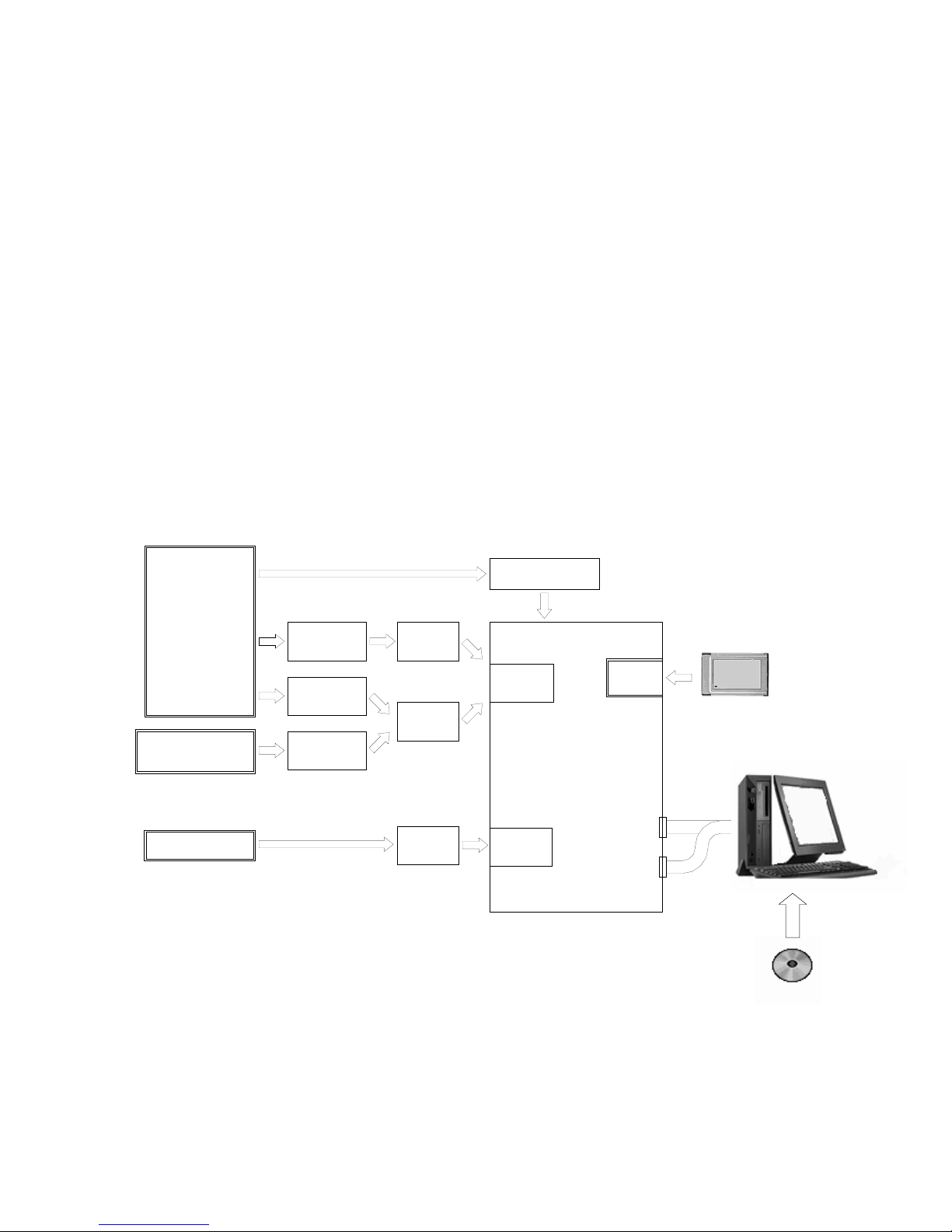
1-2 SYSTEM CONFIGURATION
Objectofmeasurement
Straingage
Straingagetansducer
Civilengineering
transducerwith
temperaturemeasuring
function
DCvoltage
Thermocouple
Resistancethermometer
sensor
Potentiometersensor
USB-50/51
series
USB-70
series
USB-65A
USI-67A
USI-65A
Differentialtransformer
transducer
Slidingresistance
transducer
Contact
Rainfall
UIO-60A
or
Option
slot1
Option
slot2
USS-61/62/63
Maximum3units
(30points)
PCcardslot
RS-232C
ETHERNET
UCS 60A Control Software
Personal Computer
PC Card (Flash ATA)
- 1-1 -
2. CONTROLS AND INDICATORS
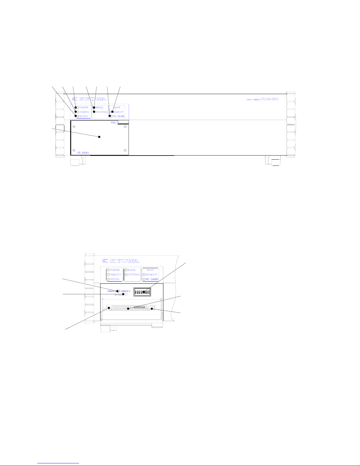
2-1 FRONT
4) 3) 2) 6) 5) 8) 7)
1)
1) PC card slot cover
2) “POWER” LED Lights up with power ON.
3) “REMOTE” LED Lights up in remote measurement.
4) “ERROR” LED Lights up when error occurred.
5) “MEAS” LED Lights up during the measurement.
6) “INTERVAL” LED Lights up in interval measurement.
7) “MEMORY” LED Lights up when saving measured data into internal memory.
12345678
8) “PC CARD” LED Lights up when saving measured data into the PC card.
C)
ON
A)
B) D)
F)
E)
A) “ENABLE/DISABLE” Switch Enables/disables the interval measurement.
B) “DISABLE” LED Lights up when the “ENABLE/DISABLE” is in “Disable” state.
C) Function Selecting Switch Switchovers various functions. (For details, see section “4-3.”)
D) PC Card Slot When saving data into the PC card, insert the PC card (ATA flush
memory card) into this PC card slot .
E) PC Card Access LED Lights up when writing data into the PC card.
Do not eject the PC card while this LED is ON.
F) Eject Button Press for ejecting the PC card.
- 2-1 -
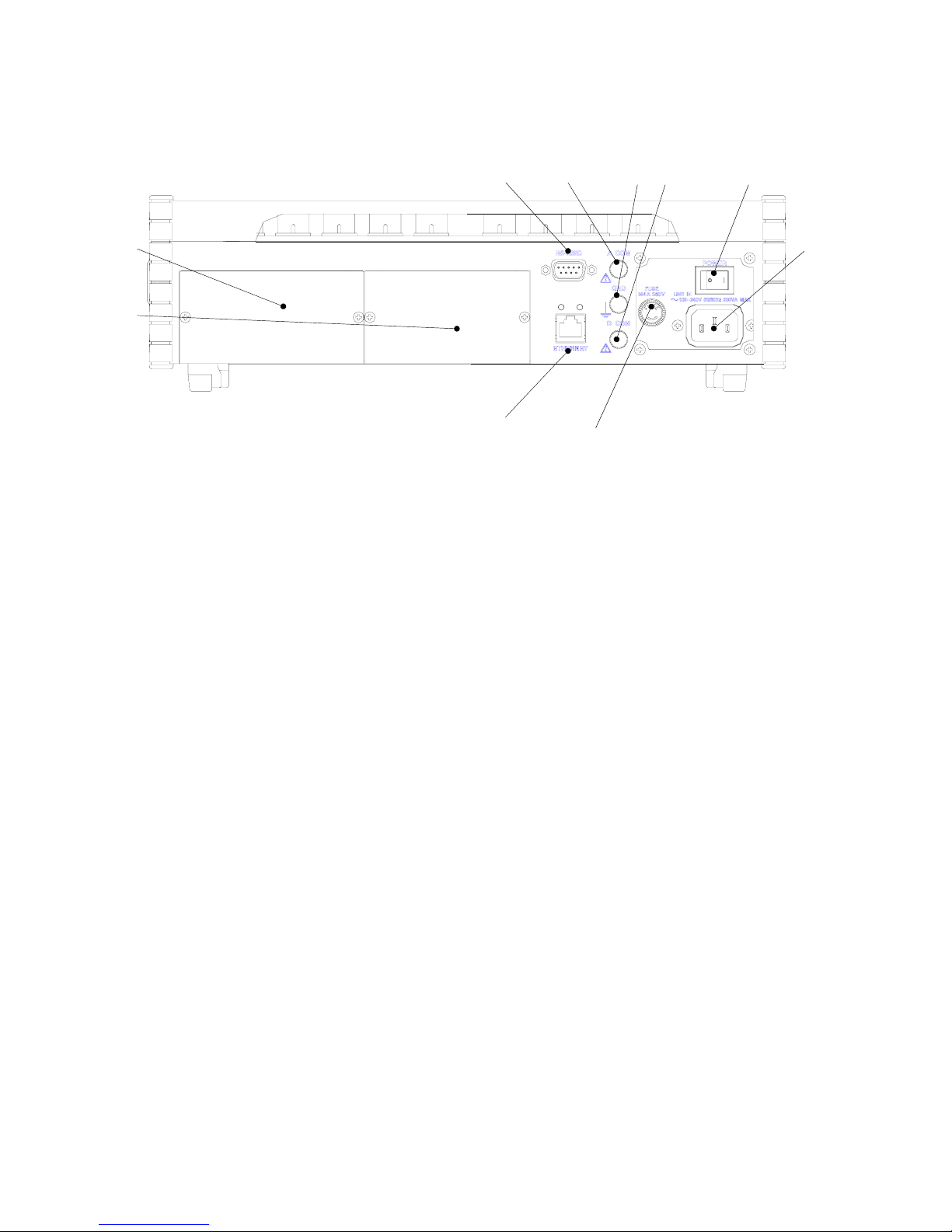
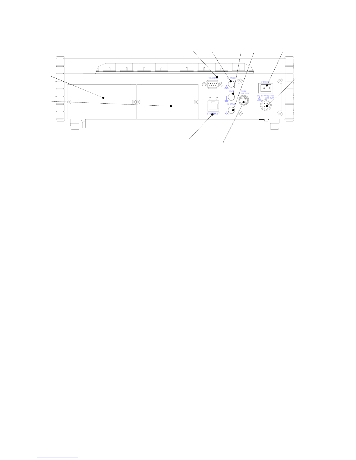
2-2 REAR
(1) AC Power Supply Version
3) 5) 6) 7) 8)
1) 9)
2)
4) 10)
1) Option slot 1 Scanner interface USI-65A or USI-67A is inserted into this slot.
2) Option slot 2 External input/output unit UIO-60A is inserted into this slot.
3) “RS-232C” connector RS-232C interface connector
4) “ETHERNET” connector Ethernet interface connector
5) “A COM” terminal Common terminal of analog signals
6) “GND” terminal UCAM-65A ground terminal
7) “D COM” terminal Common terminal of digital signals
8) “POWER” switch Power switch
9) “LINE IN” connector Power input connector
10) “FUSE” holder Fuse holder
- 2-2 -
(2) DC Power Supply Version
3) 5) 6) 7) 8)
1) 9)
2)
4) 10)
1) Option slot 1 Scanner interface USI-65A or USI-67A is inserted into this slot.
2) Option slot 2 External input/output unit UIO-60A is inserted into this slot.
3) “RS-232C” connector RS-232C interface connector
4) “ETHERNET” connector Ethernet interface connector
5) “A COM” terminal Common terminal of analog signals
6) “GND” terminal UCAM-65A ground terminal
7) “D COM” terminal Common terminal of digital signals
8) “POWER” switch Power supply switch
9) “DC IN” connector DC power input connector
10) “FUSE” holder Fuse holder
- 2-3 -
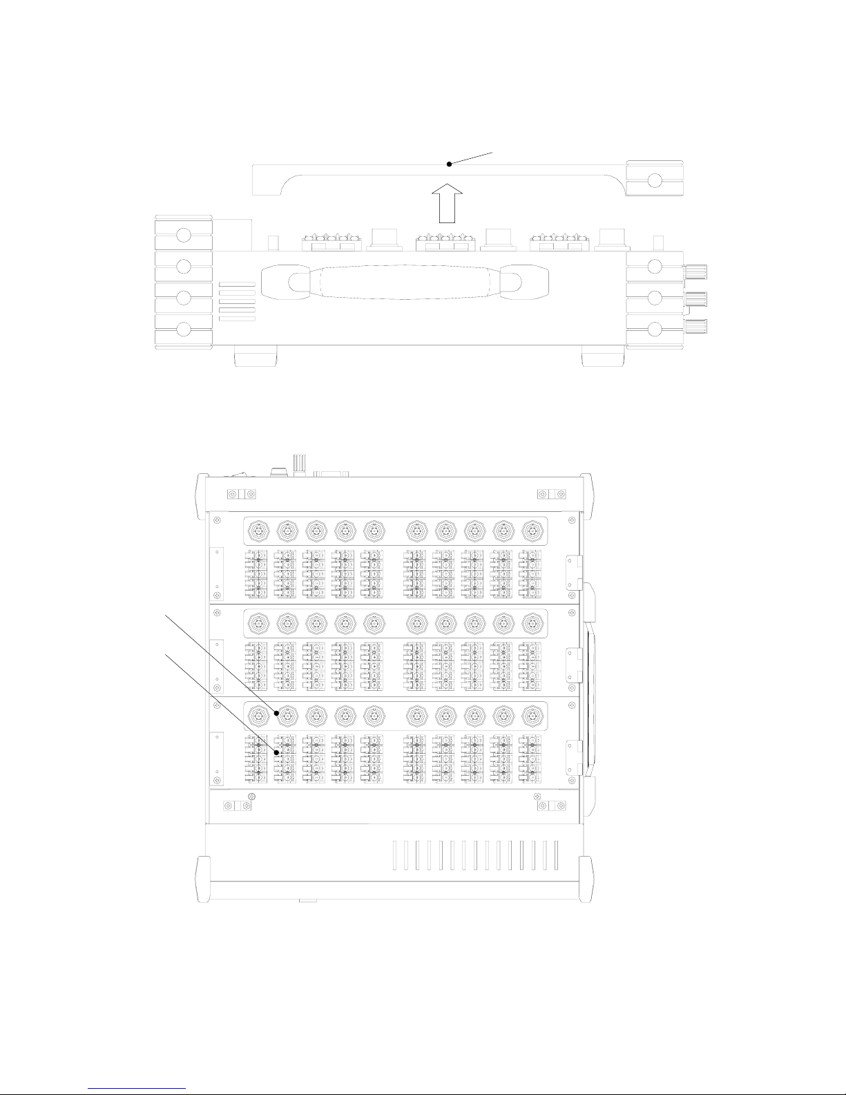
2-3 TOP
1)
* Remove the top cover to the arrow direction.
←CH20 to 29
3)
2) ←CH10 to 19
←CH00 to 09
1) Top cover
2) Input terminal board
3) NDIS standard connector (Provideded only for USS-62A scanning unit)
* The above figure is an example mounted with three USS-62As.
- 2-4 -
3. CONNECTING DEVICES & PREPARING FOR MEASUREMENT
3-1 SYSTEM INSTALLATION
3-1-1 Grounding
Always ground the GND terminal to prevent the UCAM-65A from being affected by noise as well as receiving
electric shock due to leaks in the electric current. For wire rods, it is recommended to use green color vinyl coated
wire having a diameter of more than 0.75 mm
2
.
Grounding standard is not in the same way according to the operating environment. See the following grounding
examples and consider the appropriate grounding method so as to reduce adverse effect from noise and to enable a
stable measurement.
Basis of the grounding is one-point grounding. If the grounding is made at more than 2 points, it should be noted that
a loop may be formed resulting to cause the UCAM-65A easily affected by noise.
In addition, grounding should be independently made from the power system.
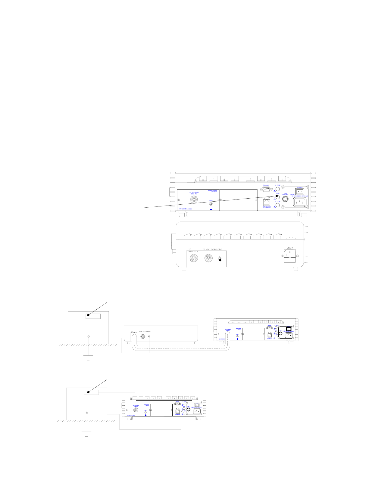
•UCAM-65A Rear
“GND” Terminal
•Scanner Rear
“GND” Terminal
3-1-1-1 When Measuring Target is Grounded
(1) Connect the measuring target to a “GND” terminal of a scanner in USB-70 series, etc.
(2) If no scanner is used, connect the measuring target to a UCAM-65A “GND” terminal.
Measuring target Sensor
To input terminal UCAM-65A
Scanner
Grounding is made by
Ground connection cable
Measuring target Sensor
To input terminal
UCAM-65A
Ground
- 3-1 -

3-1-1-2 When Measuring Target is Insulated From Ground
(1) Connect the measuring target to a “GND” terminal of a scanner in USB-70 series, etc.
(2) If no scanner is used, connect the measuring target to a “GND” terminal of the scanner in the USB-70 series, etc.
(3) Ground either one of the “GND” terminal of the scanner in the USB-70 series, etc., or a UCAM-65A “D COM”
terminal.
Measuring Target Sensor
To input terminal UCAM-65A
Scanner
Insulator Grounding is made by
Ground Connection cable.
Measuring target Sensor
To input terminal
UCAM-65A
Insulator
Ground
3-1-1-3 When Measuring Target has Potential to the Ground
(1) Ground either one of the “GND” terminal of the scanner in the USB-70 series, etc., or a UCAM-65A “D COM”
terminal.
Sensor
To input terminal UCAM-65A
Scanner
DC
Within±50V
Grounding is made
by connection cable. Ground
(2) Do not ground the “A COM” terminal. Or, it may lower the performance and cause trouble.
- 3-2 -

3-1-1-4 When Connecting to External Device with Digital Common Not Connected to GND
Terminal
(1) Connect a UCAM-65A “GND” terminal to a GND terminal of the external device.
(2) Ground either the UCAM-65A “GND” terminal or GND terminal of the external device.
Interface connecter of the UCAM-65A
external device
External
device
Grounding is made by interface cable.
3-1-1-5 When Connecting to External Device with Digital Common Connected to GND terminal
(or Chassis)
(1) Connect a “GND” terminal of the UCAM-65A to a GND terminal of the external device.
(2) Ground the GND terminal of the external device.
Interface connector of UCAM-65A
external device
External
device
Grounding is made by interface cable.
- 3-3 -
 Loading...