

Page 1
※ご使用前にこの説明書を良くお読みになり十分に理解してください。
Before beginning assembly, please read these instructions thoroughly!
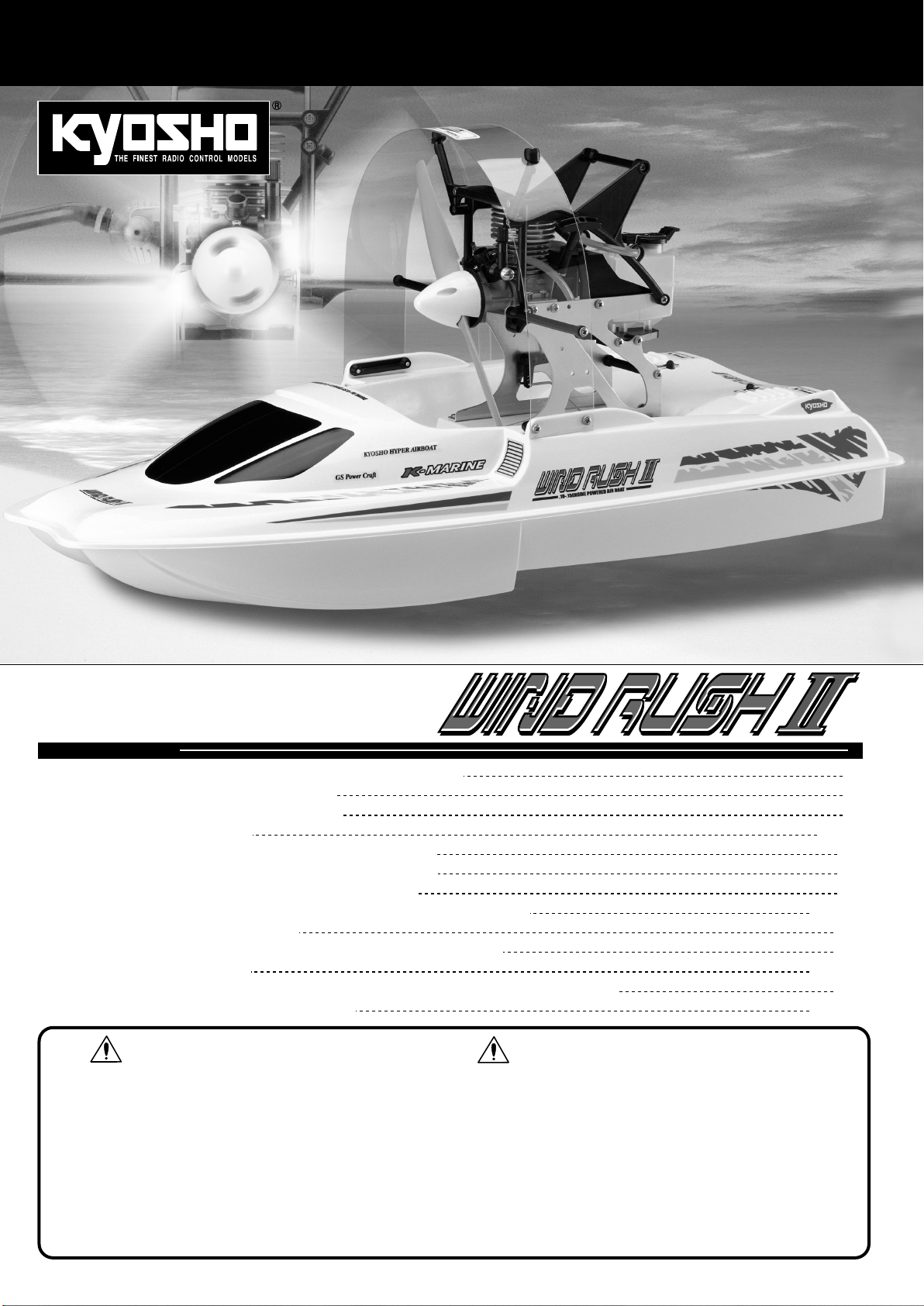
LENGTH: 620mm (24.4")
1:12 SCALE RADIO CONTROLLED
.10~.15 ENGINE POWERED AIR BOAT
目 次
●キットの他にそろえる物/
●プロポの準備/
●組立て前の注意/
●本体の組立て/
●取扱いの注意/
●走航前のチェック/
●エンジン各部名称と働き/
●エンジンの始動・ブレークイン/
●走航後の手入れ/
●故障?と思う前に/
●分解図/
●スペアパーツ・オプションパーツリスト/
●スペアパーツ・オプションパーツ購入方法
INDEX
REQUIRED FOR OPERATION 2
RADIO PREPARATION
BEFORE YOU BEGIN
ASSEMBLY
OPERATING YOUR MODEL SAFELY
CHECKLIST BEFORE RUNNING
ENGINE DESCRIPTION
ENGINE STARTING & BREAK IN
MAINTENANCE
IN CASE THE ENGINE DOES NOT START
EXPLODED VIEW
SPARE PARTS & OPTIONAL PARTS
安全のための注意事項
この無線操縦模型は玩具ではありません!
●この商品は高い性能を発揮するように設計されています
ので組立てに不慣れな方は、模型を良く知っている人に
アドバイスを受け確実に組立ててください。
●
組立て作業は、幼児の手のとどかない所で行ってください
●動かして楽しむ場所は万一の事故を考えて、安全を確認
してから責任をもってお楽しみください。
●組立てた後も説明書がいつでも見られるように大切に保
管してください。
※製品改良のため、予告なく仕様を変更する場合があります。
*SPECIFICATIONS ARE SUBJECT TO BE CHANGED WITHOUT NOTICE.
© 2004 KYOSHO CORPORATION
/禁無断転載複製
。
INSTRUCTION MANUAL
組立/取扱説明書
SAFETY PRECAUTIONS
This radio control model is not a toy.
●
First-time builders should seek the advice of experienced
modellers before beginning assembly and if they do not fully
understand any part of the construction.
●
Assemble this kit only in places out of children's reach!
●
Take enough safety precautions prior to operating this model.
You are responsible for this model's assembly and safe
operation!
●
Always keep this instruction manual ready at hand for quick
reference, even after completing the assembly.
No. 41424(GS15PR付)
No. 41425(GS15PRタッチスターター付)
No. 41426(OS10FP‑B(K)付)
3
3
4~16
17
18
18
18~22
23
23
24~25
26
27~28
Page 2
キットの他にそろえる物
REQUIRED FOR OPERATION
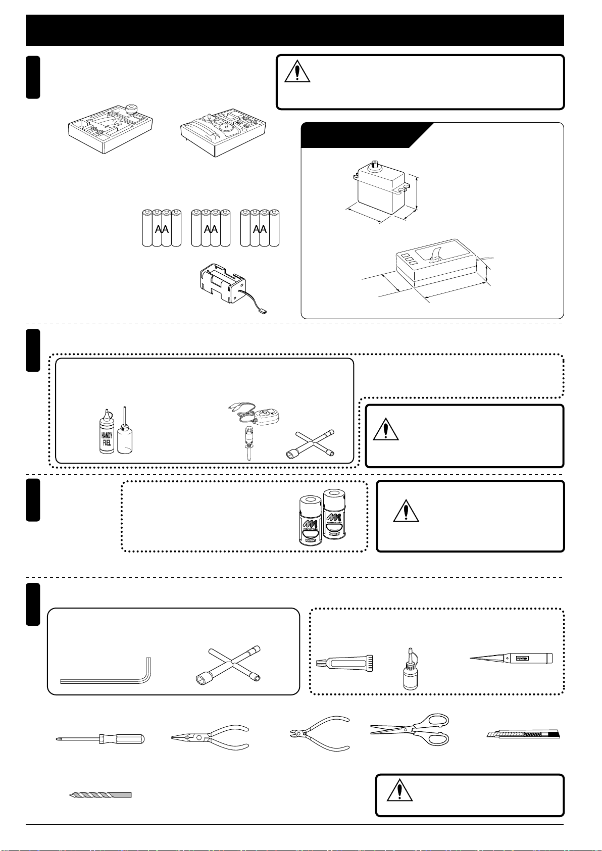
BEC仕様2チャンネル2サーボ仕様無線操縦機(プロポ)
2-channel radio with 2 servos.
1
■ハンドルタイプ
Wheel-type
■スティックタイプ
Stick-type
●プロポの取扱いは、プロポに付属の説明書を参考に
してください。
For more information on the radio, refer to its instruction manual.
■単3乾電池
AA-size Batteries
AA AA AA
■電池ボックス
Battery Box
●プロポセットに付いているときは
必要ありません。
If already supplied with the radio,
there is no need to purchase a battery
box separately.
燃料と始動用具
2
Required for engine starting:
●エンジン始動に必要な用具をセットにしました。
No.73201
■グロー燃料、燃料ポンプ ■プラグレンチ
Glow Fuel & Fuel Pump Plug Heater / Charger
スーパースターターパック
■プラグヒーター/充電器
No.695142
DC急速充電器
DC Quick Charger
No.695145
スパークブースター
Spark Booster
Super Starter Pack
水上用(ボート用)のプロポ(2チャンネル2サーボ仕様)セット
を必ず使用してください。(水上用以外使用禁止)
注意
CAUTION: Only use a surface radio with 2 channels and
2 servos !
使用できるサーボ、受信機サイズ
Servo and Receiver sizes
約40mm
Approx. 40mm
約33mm
Approx. 33mm
41425タッチスターター付キットの場合、プラグヒー
ター/充電器は不要です。
ForNo.41425versionwithTouchStarter,theplug
Plug Wrench
heaterandchargerarenotrequired.
No.80312
ロッキングジグ/レンチ
Lockingjig/wrench
警告
※
このサーボでも一部使用できない
場合があります。
Install suitably sized servos &
receiver as indicated below.
約36mm
Approx. 36mm
約20mm
Approx. 20mm
約20mm
Approx. 20mm
約47mm
Approx. 47mm
ガソリンや灯油は使用禁止
WARNING:
Gasoline or kerosene
cannot be used.
耐燃料塗料
3
Fuel-proof paint
組立てに必要な工具
4
Tools required
キットに入っている工具
TOOLS INCLUDED
■六角レンチ(1.5mm)
Hex Wrench (1.5 mm)
■+ドライバー(大、中、小)
Phillips Screwdriver (L, M, S)
■ドリル(2.5,3mm)
Drill(2.5, 3mm)
No.76301 〜 76403
京商スプレーカラー
KYOSHO SPRAY COLOR
K
O
Y
H
S
O
S
P
より強力な耐燃料性を必要とする場合はウレタン系塗料を使用する。
If greater fuel resistance is required, use a urethane paint.
R
O
R
L
A
O
Y
C
R
組立工程の中で塗料が必要です。
Paintisrequiredduringtheassemblyprocess.
■シリコンシール ■KYOSHO
■プラグレンチ
Plug Wrench
■ラジオペンチ ■ニッパー
Needle Nose Pliers
Wire Cutters Scissors
K
O
Y
H
S
O
S
P
R
O
R
L
A
O
Y
C
R
Silicone Sealant
No.96152
SILICONE SEAL
注意
スペシャルグルー
KYOSHO Special Glue
No.96154
■ハサミ
スプレーカラーを使用する場合、
缶の説明を良く読んでください。
CAUTION: Before using
Kyosho Spray Colors,
always read the instructions.
■ナイフエッジリーマー
KNIFE EDGE REAMER
No.695101
瞬間接着剤
Instant Glue
KYOSHO
Special Glue
■カッターナイフ
Sharp Hobby Knife
使用する工具の取扱いには、
十分注意してください。
注意
CAUTION: Handle tools carefully!
2
Page 3
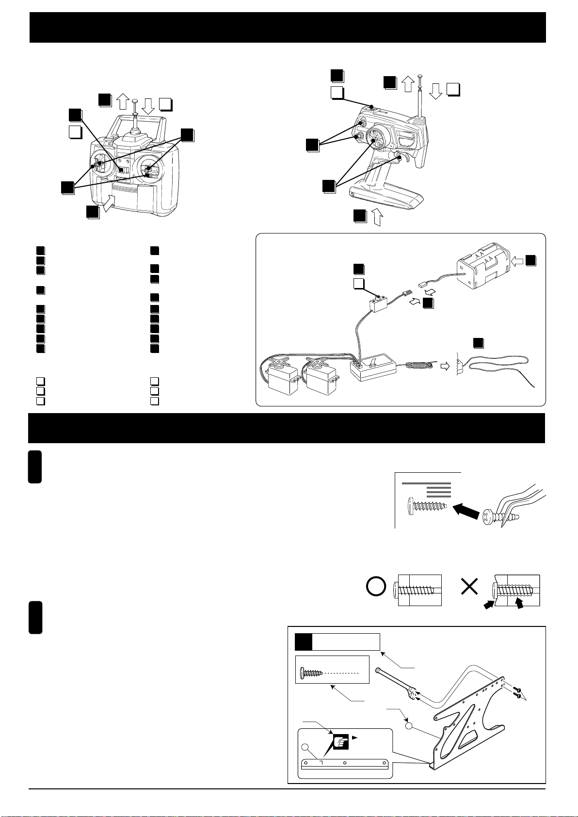
プロポの準備
RADIO PREPARATION
●プロポを下の順番にしたがってセットします。
Set up the radio as explained below.
■スティックタイプ ■ハンドルタイプ
Stick-type
ON
7
11
OFF
2
12
9
送信機
▲
Transmitter
Wheel-type
6
ON
7
11
OFF
2
12
6
送信機
▲
Transmitter
9
1
●始める時
1
送信機に単3乾電池をセットする。
2
送信 機の アン テナ をの ばす。
3
電池ボックスに単3乾電池を
セットする。
電池 ボッ クス のコ ネク ター
4
をつなぐ。
受信 機の アン テナ をの ばす。
5
トリ ムを 中央 にセ ット する。
6
送信 機の スイ ッチ を入 れる。
7
8
受信 機の スイ ッチ を入 れる。
9
ハンドル/ト リガーを動かし
てサーボが動いているか確認。
●終わる時
10
受信機のスイッチを切る。
11
送信機のスイッチを切る。
12
送信 機の アン テナ を縮 める。
●START
1
Insert AA-size batteries into
the Transmitter.
2
Extend the Transmitter antenna.
3
Insert the AA-size batteries
into the battery box.
4
Plug in the battery box.
Unwind the Receiver
5
Center the Transmitter trims.
6
Switch "ON" the Transmitter.
7
8
Switch "ON" the Receiver.
9
Make sure the servos move according to your transmitter inputs.
●FINISH
10
Switch "OFF" the Receiver.
11
Switch "OFF" the Transmitter.
12
Retract the Transmitter antenna.
antenna.
▲
サーボ
Servo
組立て前の注意
BEFORE YOU BEGIN
組立ての前に下記のことに注意してください。
1
Before assembling, please read the following carefully:
●この説明書を良く読み、構造を理解する。
First, read through this instruction manual and understand the modelÕs con-struction.
●小さな部品の形やサイズを間違えないようにする。図を参考にして確認しながら組立てる。
Do not use the wrong size or shaped small parts. Check the illustrations & use the correct
part for each step of assembly.
●キットの内容を確かめる。
※万一不良、不足がありましたら、お買い求めの販売店か、当社「ユーザー相談室」までご連絡ください。
Check the contents of this kit. Should parts be missing, immediately contact the retail shop or your nearest Kyosho distributor.
●TPビス締をめるときは・・・
締めこみが固くても部品が固定されるまで締めてください。ただし、部品が変形するまで締めるとビスがきかなくなります。
When tightening a self-tapping (TP) screw: continue tightening until fastened correctly,
even if screw is hard to turn.
However, do not overtighten it as the plastic thread inside the part may strip!
説明書の見かた
2
How to read the instruction manual:
A:
この項目で組立てるおおよその場所。
B:
小物部品の名前、原寸図、使用数。
C:
キット内の部品は、ビス類を除いてキーNo.が付けられています。
スペアパーツを
D:
説明書内では多くのマークが使用されています。
マークに注意して組立てを進めてください。マークの説明は、
各ページの下にあります。
A: Indicates the assembly step number and the section that will
be assembled.
B: Key Number, Part Name, True-to-scale Diagram, Quantity Used.
C: All parts except screws are identified by key numbers.
For purchasing spare parts, find the key number of the part
needed in the spare parts list and refer to the left column for the
corresponding order number.
D: This instruction manual uses several symbols.
Please note them during the entire assembly at the bottom of
each page.
購入する時はキーNo.を参照してください。
説明例
〔Example〕
フレーム
Frame
6
3 x 10mm
TP Screw
D
12
TPビス
1
8
ON
10
OFF
▲受信機
Correct
2
B
Lの刻印
"Left" side mark.
▲スイッチ
Switch
Receiver
A
C
3
4
▲電池ボックス
Battery Box
5
Wrong
3 x 10mm
12
3
Page 4
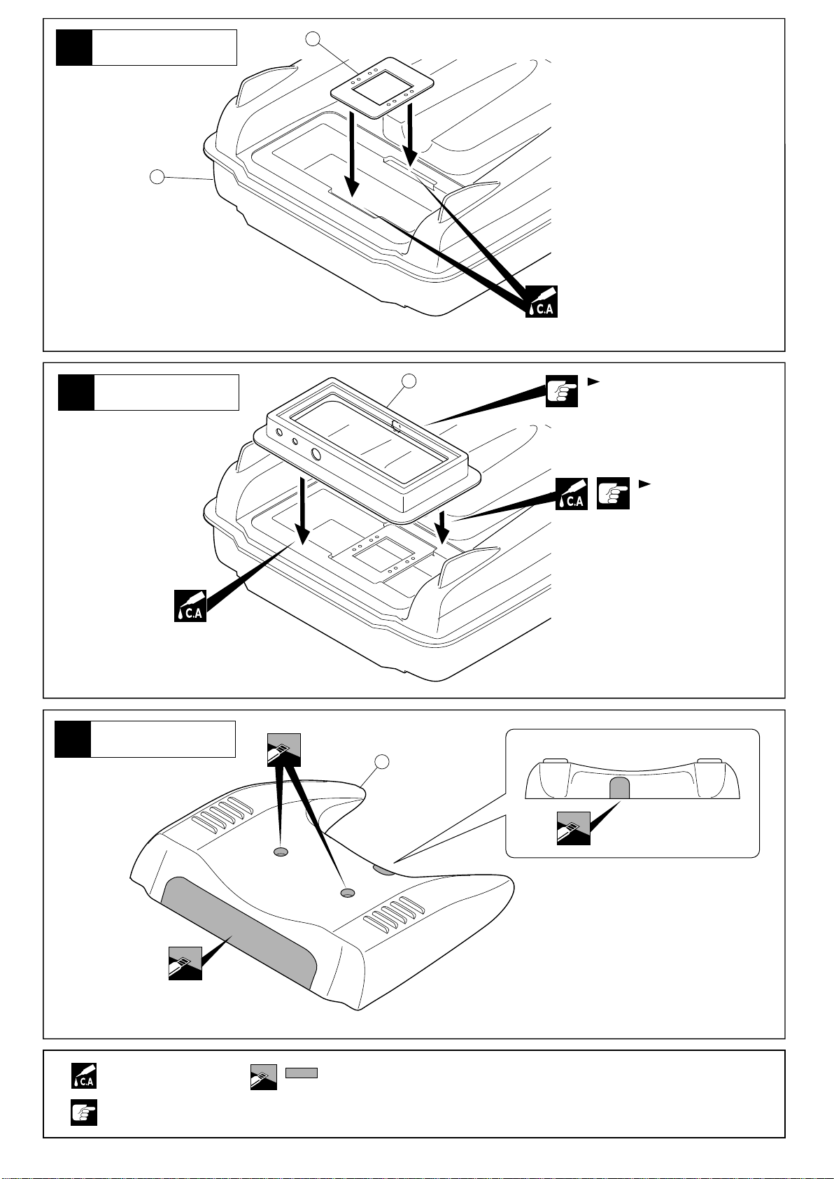
1
メカボックス
Radio Box
1
2
2
3
メカボックス
Radio Box
カウリング
Cowling
3
4
向きに注意。
Note the direction.
防水のためすき間を
なくす。
Leave not gaps so
it will be waterproof.
瞬間接着剤で接着する。
Apply instant glue
(CA glue, super glue).
注意して組立てる所。
Pay close attention here!
をカットする。
Cut off shaded portion.
4
Page 5
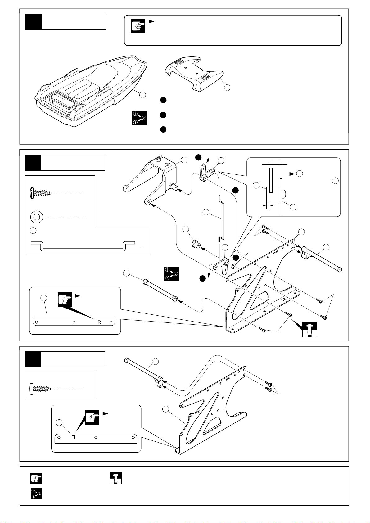
4
塗装
Painting
ABS樹脂製品はグロー燃料に侵され
内側、外側を必ず耐グロー燃料塗料を厚めに塗装する。
Coat the hull's interior and exterior surfaces with glow fuel-resistant coating
as the shape of the ABS resin material may change if soaked in glow fuel.
1
1
塗装前に、中性洗剤で油やよごれを洗う。
Before painting, remove any dirt or oil by washing with mild detergent.
水分を完全に乾かす。
2
Completely dry the surfaces to be painted.
3
耐燃料用塗料で塗装する。
Coat in fuel-resistant paint.
ると変質やひび割れするので、船体の
4
フレーム
5
Frame
3 x 10mm
TP Screw
3mm
Washer
11
TPビス
ワッシャー
スロットルロッド(C)
Throttle Rod (C)
5
6
1
Rの刻印
Right side mark
1
8
7
長
Long
7
7
の向きに注意。
Note direction of
7
4
短
11
9
1
7
Short
3 x 10mm
3mm
5
5
6
3
10
2
3 x 10mm
3 x 10mm
フレーム
6
Frame
3 x 10mm
TP Screw
TPビス
12
注意して組立てる所。
Pay close attention here!
番号の順に組立てる。
Assemble in the
specified order.
6
2
3 x 10mm
Lの刻印
Left side mark
仮止め。
Tentatively tighten.
12
5
Page 6
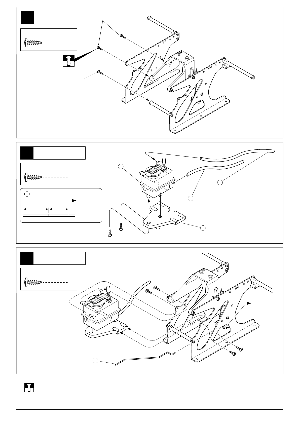
7
フレーム
Frame
3 x 10mm
3 x 10mm
TP Screw
8
3 x 10mm
TP Screw
15
160mm 120mm
TPビス
燃料タンク
Fuel Tank
TPビス
シリコンチューブ
Silicone Tube
3
3 x 10mm
2
カットする。
Cut off.
13
15
シリコンチューブ(160mm)
Silicone Tube(160mm)
15
シリコンチューブ(120mm)
Silicone Tube(120mm)
燃料タンク
9
Fuel Tank
3 x 10mm
TP Screw
TPビス
14
4
外側の穴
Outside holes.
16
仮止め。
Tentatively tighten.
6
Page 7
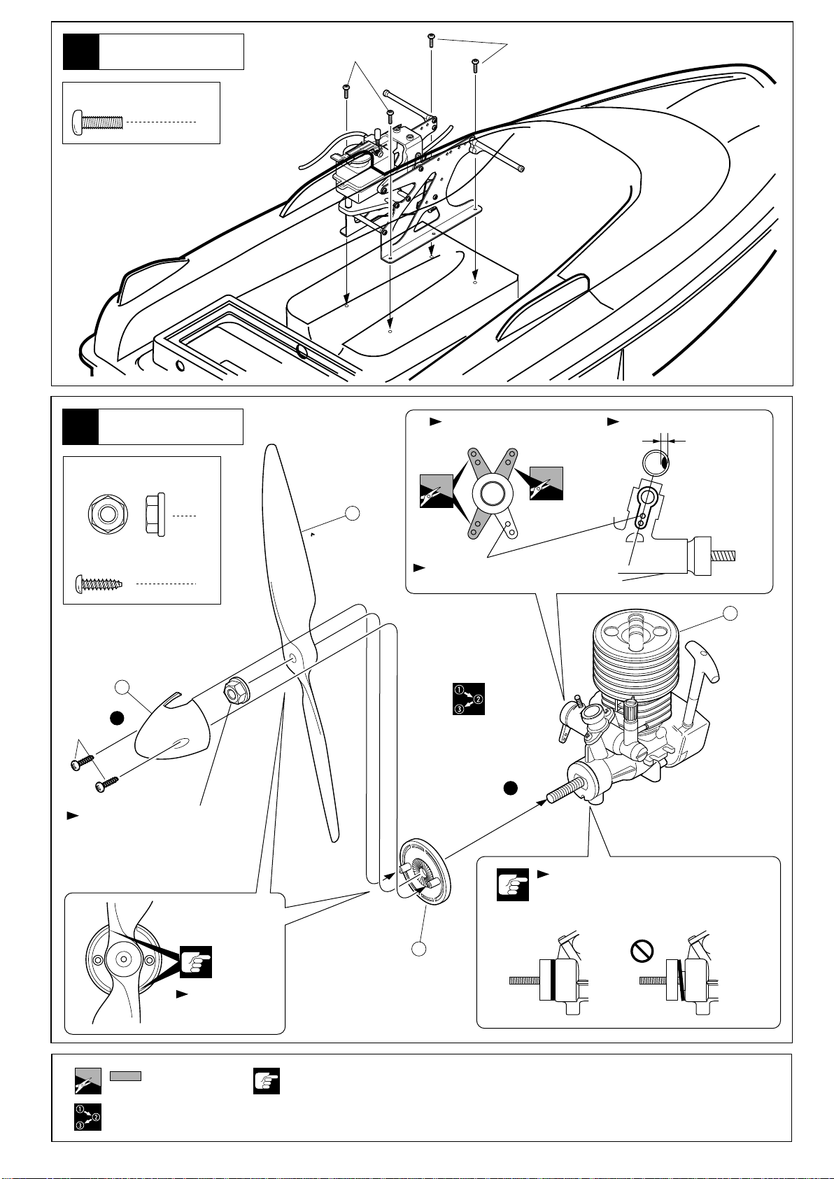
10
船体
Hull
3 x 10mm
3 x 10mm
3 x 10mm
Screw
ビス
エンジン
11
Engine
5mm
フランジナット
Flanged Nut
4
GS15PR OS10FP
約1mm
Approx. 1mm
2.6 x 10mm
TP Screw
TPビス
18
2
2.6 x 10mm
5mmフランジナットをエンジン
から一度外して、プロペラを
おさえながらしめる。
Remove 5mm Flanged Nut from
engine and hold the propeller in
place while re-tightening the nut.
1
2
19
この穴を使用。
Use this hole.
17
1
シムがエンジンのシャフトにひっかから
ないように注意する。(GS15PR)
Make sure the shim is held flat between
the engine and drive washer (GS15PR).
をカットする。
Cut off shaded portion.
番号の順に組立てる。
Assemble in the
specified order.
溝に合わせる。
Alignwithgrooves.
注意して組立てる所。
Pay close attention here!
20
7
Page 8
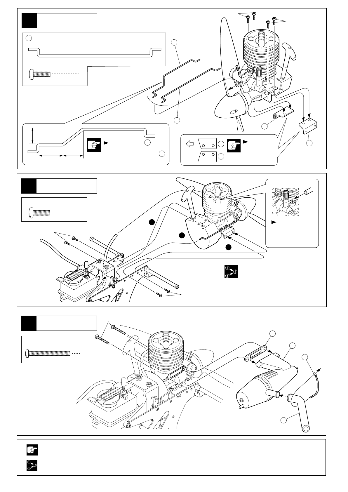
船体
12
Hull
24
スロットルロッド(D)
Throttle Rod (D)
24
OS10FP
3 x 10mm
3 x 10mm
3 x 10mm
Screw
ビス
9mm
14mm 13mm
エンジン
13
Engine
3 x 10mm
Screw
ビス
3 x 10mm
1
4
24
GS15PR
22
OS10FPの場合、を図の
寸法に曲げる。
If using OS10FP, bend
as shown.
4
24
24
前
Front
22
23
2
1
向きに注意。
Note the
direction.
23
キャブレターに
差し込む。
Connect to
carburettor.
2
マフラー
14
Muffler
2.6 x 25mm
Screw
ビス
注意して組立てる所。
Pay close attention here!
番号の順に組立てる。
Assemble in the
specified order.
3 x 10mm
2.6 x 25mm
25
26
2
27
28
8
Page 9

15
フレーム
Frame
3 x 10mm
3 x 10mm
TP Screw
TPビス
10
31
30
6
30 31
と の
向きに注意。
Note direction
of & .
31
30
3 x 10mm
29
10
31
30
向きに注意。
3 x 10mm
Note the direction.
29
フレーム
16
Frame
3 x 10mm
Screw
ビス
2
マフラーヘ
Connect to muffler
で仮組したビス。
7
Screw from Step 7.
3 x 10mm
3 x 10mm
で仮組したビス。
5
Screw from Step 5.
注意して組立てる所。
Pay close attention here!
9
Page 10

17
船体
Hull
32
3 x 10mm
3 x 10mm
TP Screw
TPビス
3mm
ラダー
18
Rudder
3 x 10mm
TP Screw
TPビス
3 x 10mm
8
33
34
35
1
33
33
前
Front
向きに注意。
Note the
direction.
3 x 10mm
37
ラダー
19
Rudder
3 x 10mm
TP Screw
3 x 16mm
TP Screw
2mm
Nut
TPビス
TPビス
ナイロンナット
37
Oリング
O-ring
36
1
2
40
2
1
1
3
3 x 10mm
10
左右同じように組立てる。
Assemble left and right
sides the same way.
注意して組立てる所。
Pay close attention here!
39
キリで穴をあける
(例1.5㎜)
Make hole with Awl.
1.5mm
(example: 1.5mm).
可動するように組立てる。
Ensure smooth non-binding
movement while assembling.
3 x 16mm
番号の順に組立てる。
Assemble in the
specified order.
38
Page 11

メカボックス
20
Radio Box
3 x 10mm
TP Screw
TPビス
スロットルサーボ
ラダーサーボ
Rudder Servo
8
Throttle Servo
21
22
44
Oリング P2
O-ring P2
46
Oリング P5
O-ring P5
メカボックス
Radio Box
41
アンテナ
Anntena
メカボックス
Radio Box
アンテナ
Anntena
1
1
プロポの説明書を参考にしてコネクター
を接続する。
Connect as per radio instruction manual.
41
OFF
ON
47
3
1
スイッチ
Switch
受信機
Receiver
48
防水テープ
42
Tape
電池ボックス
Battery Box
スイッチ付属
Supplied with the switch
44
46
45
別購入品。
Must be purchased
separately!
瞬間接着剤で接着する。
Apply instant glue
(CA glue, super glue).
2
46
45
44
43
番号の順に組立てる。
Assemble in the
specified order.
<ON>
<OFF>
11
Page 12

23
メカボックス
Radio Box
スロットルロッド(A)
49
Throttle Rod (A)
3 x 3mm
Set Screw
セットビス
サーボ付属
Supplied
with the servo.
六角レンチ(1.5mm)
Hex Wrench
1
2
3 x 3mm
49
2
3
1
5151
50
50
この穴を使用。
Use this hole.
16mm
3×3mmセットビスで
調整する。
Position as per diagram
and tighten the 3x3mm
Set Screws.
ニュートラル
Neutral
A B
スロットルハイ エンジンストップ
Full Throttle
A=B
Stopping Engine
スロットルトリムを
バック側に動かす。
Move throttle trim to
the reverse side.
12
別購入品。
Must be purchased
separately!
をカットする。
Cut off shaded portion.
1mm
番号の順に組立てる。
Assemble in the
specified order.
注意して組立てる所。
Pay close attention here!
瞬間接着剤で接着する。
Apply instant glue
(CA glue, super glue).
Page 13

メカボックス
24
Radio Box
52
ラダーロッド
Rudder Rod
3 x 3mm
Set Screw
六角レンチ(1.5mm)
Hex Wrench
セットビス
この穴を使用。
Use this hole.
1
1
サーボ付属
Supplied
with the servo.
13mm
1
52
2
3
50
メカボックス
25
Radio Box
3 x 10mm
TP Screw
TPビス
角度を合わせセットビスを締め込む。
Adjust the angle as shown, and then
tighten the set screws.
90°
90°
53
2
をカットする。
Cut off shaded portion.
番号の順に組立てる。
Assemble in the
specified order.
3 x 10mm
別購入品。
Must be purchased
separately!
瞬間接着剤で接着する。
Apply instant glue
(CA glue, super glue).
注意して組立てる所。
Pay close attention here!
54
13
Page 14

26
メカボックス
Radio Box
防水テープ
Waterproofing
Tape
42
すき間のないように貼る。
Attach tape without gaps.
船体
27
Hull
3 x 10mm
TP Screw
TPビス
3 x 10mm
部分に 防水
テープを貼る。
Attach tape to
the area.
55
1
80mm
42
28
カウリング
Cowling
2.5mm
56
57
5mm
4
14
キリで穴をあける
(例1.5㎜)
Make hole with Awl.
1.5mm
(example: 1.5mm).
注意して組立てる所。
Pay close attention here!
Page 15

デカール
Decal
29
図の位置にデカールをはる。
Apply the decals to the spots indicated.
ナンバーのついていないデカールは好きな位置に貼る。
Decals with no number apply any place.
カッコの中は反対側用のデカールナンバーです。
The decal numbers between brackets are only for the opposite side.
17
1 3
42 687 5
15
16
( )
13
14
( )
11
12
( )
10
9 1 2
( ) ( )
15
Page 16

スターター
30
Starter
3 x 16mm
TP Screw
TPビス
3 x 10mm
3 x 16mm
2
59
一度外して取り付ける。
Remove screws to attach.
No.41425
タッチスターター付キット
Kit with Touch Starter
コネクターユニット
Connector Unit
31
同じ色のコードを接続する。
Connect to the same color.
No.41425
タッチスターター付キット
Kit with Touch Starter
61
7.2Vバッテリー
7.2V Battery
60
16
注意して組立てる所。
Pay close attention here!
42
Page 17

取扱いの注意
OPERATING YOUR MODEL SAFELY
事故やケガ等の危険防止のため、次のことを必ずお守りください。
In order to avoid accidents and personal injury, be sure to observe the following:
●R/Cボートは、湖や河川などの水辺で楽しむものです。
操縦する方や同行の方が思わぬ事故に合わないように
注意し、必ず安全な場所で走航させてください。
Discover a new world of pleasure with R/C boats.
Wheth-er you run your boat on lakes, rivers or elsewhere, take precautionary measures to avoid accidents.
●ケガの恐れがあるので回転
部分に手や物を入れないよ
うにしてください。
Do not put your hands or
any objects into rotating
parts, as this could result in
serious accidents!
●燃料の取扱いは、必ず屋外で。
燃料の蒸気、排気ガスは有
害です。
Handle fuel ONLY outdoors!
Vapors and exhausts are
very noxious and dangerous
to your health!
●走航直後は、エンジン、マ
フラー周辺は高温になって
いるので、すぐにはさわら
ない。ヤケドの原因になり
ます。
Right after use, do NOT
touch equipment on the
model such as the engine
and muffler, because they
generate high temperatures!
You may burn yourself
seriously by touching them!
●燃料は、模型用グロー燃料
を必ず使用する。ガソリン
や灯油の使用は、火災等の
事故の原因になります。
ONLY use glow fuel for radio
control models! NEVER use
gasoline and kerosene in
R/C models as they cause
fire.
禁止
PROHIBITED
禁止
PROHIBITED
●燃料は、引火性があります。
Fuel is highly inflammable and highly explosive!
火気のあるところや室内では絶対に使用しない。
NEVER use fuel indoors or in places with open fires and
sources of heat!
保管は、キャップをしっかりしめ、幼児の手の届かない
冷暗所に置くこと。
Store fuel ONLY in cool, dry and dark places out of
childrenÕs reach! Tightly shut the cap!
使用後の空缶は、火中には投げ入れない。爆発の原因に
なります。
Do NOT dispose of empty fuel
cans into a fire! There is danger
of explosion!
●次のような時や、次のような場所では絶対に走航させ
ないでください。思わぬ事故やケガの原因となります。
For accident prevention, do not run your model under
the following circumstances:
海または海水面など。
In the sea or in other salt water.
人が多い場所。
In areas where there are lots of people.
河川が増水しているとき、また流れが速いとき。
When rivers are swollen or their current is strong!
風が強いとき。
In strong winds.
同じバンドの無線操縦模型がそばにいるとき。
Also make sure that nobody is using the same
frequency as you are at the same time!
01
01
●燃料は、飲んだり、目に入
れたりしない。万一、事故
が起きた場合は、吐かせる、
洗眼する等をした後、すぐ
に医師の診察を受けてくだ
さい。
DO NOT swallow fuel and
avoid contact with eyes! Do
the following immediately: if
fuel is swallowed, in-duce
vomit-ing. If fuel gets into
eyes, rinse them and consult
an orphamologist!
プロポの電池残量が少ないとき。
When radio batteries are low on power!
船の動きがおかしい???とき。
When the boat behaves or operates strangely!
?
?
?
?
?
17
Page 18

走航前のチェック
CHECKLIST BEFORE RUNNING
□ビスなどのゆるみはありませんか?
□可動部分はスムーズに動きますか?また、グリス等適切に塗
ってありますか?
□
燃料パイプの詰まりやひび割れ、接続の不良はありませんか?
□マフラーや、エキゾーストパイプ等の接続に不良はありませ
んか?
□送・受信機の電池はありますか?また、確実に固定されてい
ますか?
□サーボ、リンケージはスムーズで正確に動作しますか?
□走航場所は安全ですか?
□
近くで同じバンドで無線操縦模型をしている人はいませんか?
エンジン各部名称と働き
ENGINE DESCRIPTION
ニードル
混合気の燃料の量を調整する。
Needle Valve:
Adjusts the amount of fuel
inflow for the air/fuel mixture.
スロットルストップスクリュー
アイドリング時のスロットル
レバーの開き具合を調整する。
Idle Adjustment Screw:
Adjusts the carburetor opening
at idle and low speeds.
スロットルレバー
混合気の量を調整しエンジンの
回転数を制御する。
Throttle Lever:
Adjusts the amount of air/fuel mixture
inflow and controls engine rpm.
□ Are all screws securely tightened?
□ Do moving/rotating parts move smoothly? Are they greased
to ensure non-binding movement?
□ Is fuel line clear and free of cracks? Is it connected properly.
□
Are the muffler and exhaust damage-free and well connected?
□ Are the transmitter and receiver batteries fresh? Is the
battery box securely installed?
□ Do the servo horns and linkages move without binding?
□ Is the running area safe?
□ Is anybody using the same frequency as you?
グロープラグ
圧縮された混合気に点火する。
Glow Plug:
Ignites the compressed air/fuel mixture.
リコイルスターター
エンジンを始動させる。
Recoil Starter:
To crank the engine.
キャブレター
燃料と空気を混ぜ混合気を作り、
その量でエンジンの回転数
をコントロールする。
Carburetor:
Mixes air and fuel and controls
engine rpm.
1
給油
Fill the tank.
燃料の蒸気、排気ガスは有害ですので、必ず
屋外で取扱ってください。
WARNING: As exhausts and fuel vapors
警告
are noxious to health, use fuel only outdoors!
エンジンは精密部品で構成されています。
不用意に分解等をすると、エンジン本来の
性能を発揮できなくなることがあります。
リコイルスターター付エンジンの始動(1)
STARTING AN ENGINE WITH RECOIL STARTER (1)
プロポのスイッチを入れる。
2
Switch on the radio.
ON
スロットルレバー
Throttle Lever
Engines include many high-precision parts.
If disassembling engines carelessly, their
original performance may be lost!
ニードル調整。
3
Adjust the needle valve.
1
ニードルが止まるまで軽くしめる。
Gently tighten the needle valve all
the way.
エンジンの説明書を参考に指定回転
2
ゆるめる。
Refer to the engine instruction manual
and unscrew the needle valve as far
as specified.
ON
▲
確認。
Check!
スロー
Idle
1
2
18
Page 19

4
チョーク。
Choke the
engine.
プラグヒート。
ここに燃料が来たら、さらに1回
チョークボタンを押す。
When fuel reaches this point, push
the choke button one more time.
5
Heat the glow plug.
リコイルスターター付エンジンの始動(2)
STARTING AN ENGINE WITH RECOIL STARTER (2)
6
エンジン始動。
Start the engine.
1
送信機のスロットルトリムを上げ
始動しやすくする。
Engine starting becomes easier
when the throttle trim is raised.
2
エンジンを始動する。
Start the engine.
8
エンジンを止めるときは、スロットルトリムを下げるか、スロットル
スロットルトリム
Throttle Trim
リコイルスターターを50cm以上
引くとロープが切れる恐れがあ
りますのでおやめください。
Do not pull the recoil starter rope
past its 50cm limit for you may
break it.
7
暖気運転。
Run up the engine.
エンジンの回転が安定したら、スロットルトリムを通常の位置に
戻して、プラグヒートをはずす。
When rpm become stable, lower the throttle trim, and disconnect
the glow plug heater.
スティックを少し下げる。
To stop the engine, lower the Throttle Trim, or slightly lower the
Throttle Stick.
スロットル
スティック
Throttle Stick
始動後のエンジン本体、マフラーなどは、
高温になっていますので、やけどをしない
よう十分注意してください。
注意
CAUTION: Beware of burning yourself!
After starting or running, engines and
mufflers become very hot!
9
エンジン停止後、受信機、送信機の順
にスイッチを切る。
After stopping the engine,first switch
off the receiver, then the transmitter.
OFF
OFF
ブレークイン
BREAK IN
●ブレークインとは、新しいエンジンの慣らし運転のことです。
ブレークインをおこなわないとエンジンに潤滑オイルがまわら
ないために、すぐにエンジンが焼き付いてしまいます。エンジ
ンを長持ちさせるためにブレークインは必ずおこなってください。
The break-in is necessary to ÒprepareÓ brand new engines for regular
and smooth running! If you fail to break-in an engine, the lubricating
oil inside does not spread and, as a result, the engine will be caked
with burns; running becomes difficult and engine life is dramatically
shortened.
●ブレークイン中は、エンジンの回転を上げすぎると焼き付きの
原因になりますので注意してください。
Duringthebreak‑inperiod,donotoperateengineathighRPM.
Thismaydamagetheengine.
●ブレークイン中は、エンジンの回転が安定しないので、波や風の少な
いときにおこなってください。またエンストしたときの回収方法など
も考慮しておきます。
Because RPM are not stable when performing break-ins, avoid windy
days and rough seas! Also, take precautionary measures for retrieving
your boat if the engine stalls while your model is off-shore.
19
Page 20

エンジン調整
ENGINE ADJUSTMENT
●ブレークインが終了してから の順で調整してください。
Adjust in the order and once the break-in is completed.
ニードル調整(最高回転数の調整)
1
Needle Valve Adjustment (Maximum Rpm Adjustment)
「エンジンの始動」の手順でエンジンを始動し、船を走航させます。
1
Start the engine as explained in the chapter <ENGINE STARTING>
and run your boat.
2
直進でスロットルスティックをハイにしたときの船のスピードを見ます。
ニードルを10°(1コマ)ずつしめこむと、スピードが上がってきます。
最高スピードが得られる所が、ニードルの最良位置です。
Watch the speed of your boat when run-ning straight ahead at full throttle.
Tightening the needle valve 10¡ at a time will increase speed. When
your boat reaches top speed, the needle valve setting is optimal.
そこからさらに閉め込むと、エンジンの排気が見えなくなったり、スピー
3
ドが途中から落ちてきます。そのまま走行を続けると、エンジンが壊れて
しまいます。すぐにニードルをゆるめてください。ニードルの最良位置か
ら10°〜20°ゆるめた位置が、通常走航の位置です。
When tightening the needle valve further, exhausts become in-visible and
rpm decrease. Running the engine with this setting will damage it.
Immediately unscrew the needle valve. Note that for normal running, the
needle valve is unscrewed 10¡~20¡ from the valveÕs optimal setting position!
1 2
1 2
タッチスターター付エンジンの始動方法
HOW TO START THE ENGINE WITH TOUCH STARTER
電動スターター用の7.2Vバッテリーを充電し、満充電になったものを用意します。
1
Prepare a fully charged 7.2V battery.
コネクターユニットのコネクターと7.2Vバッテリーのコネクターを接続します。
2
Join the connector unit and the battery.
送信機、受信機の順で電源を入れます。リンケージが正しく動作するか、確認します。
3
キャブレターが約1mm開いていることを確認します。
Switch the transmitter ON first, then the receiver. Check if the linkages move properly.
Check that the carburetor is open about 1mm.
燃料をタンクに入れる前に、7.2Vバッテリーを、スターター配線ユニットに接続します。
4
(以後、スタートします。)
このときに、スターターがいきおい良く回転すれば正常です。(2〜3秒で中止します。)
Before filling the fuel tank, connect the 7.2V battery to the starter unit. (It will start).
If the starter rotates quickly, the setting is normal. (Turn it off after 2 or 3 seconds).
ニードル
Needle Valve
No.41425
タッチスターター付キット
Kit with Touch Starter
チョークボタン
Choke Button
スターターを5秒以上連続して回転させると、
発熱し、火災の恐れがあります。
警告
WARNING
燃料タンクに燃料を入れ、チョークボタンを押して燃料をキャブレターに送ります。
5
7.2Vバッテリーをスターター配線ユニットに接続してエンジンを始動します。このとき、スターターを5秒以上連続して回さないでく
ださい。スターターがいきおい良く回っていても、エンジンが始動しないときは、チョークボタンをさらに数回押してもう少し燃料
を送ります。エンジンが始動したらすぐにスタートをやめて下さい。
※エンジンの回転数を上げすぎないように注意。また、エンジンスタート時には、自動でプラグヒートされていますので、その他の
プラグヒーターは必要ありません。
Put fuel in fuel tank and push the Choke Button to send fuel into the carburetor. Connect the 7.2V battery to the starter-wiring unit to start
the engine. Do NOT connect the 7.2V battery for more than 5 seconds at a time. If the starter is working properly and the engine
still doesn't start, send a little more fuel to the caburetor by pushing the Choke Button a few more times. Once the engine is running,
quickly cease starting the engine.
※Be careful not to run the engine at too high RPM. Also when the engine is being started, the glow plug is being heated
automatically so please do not try to heat the plug any other way.
If you make it run for over 5 seconds,
the starter will generate heat or even set on fire.
20
Page 21

スターターが回転しない場合
IN CASE THE STARTER DOES NOT WORK
No.41425
スターターが回転しない場合には、すぐにスタートをやめて下さい。
警告
WARNING
スターター配線ユニット、コネクターユニットが正常に接続されているにもかかわらず、スターターが回転しない場合には、
エンジンに燃料が入りすぎていることが考えられます。
If the starter wiring unit and connector units are properly hooked up and the starter still doesn't start the engine properly,
it is possible the engine may be flooded with too much fuel.
次の手順で余分な燃料をエンジンから抜きます。
Remove the excess fuel by doing the following.
If the starter does not rotate, stop the starting process promptly.
タッチスターター付キット
Kit with Touch Starter
プラグを外します。
1 2
Remove the glow plug.
そのままスタートし、余分な燃料を
3
排出します。その後プラグを元通り
に取り付けて、再びスタートします。
Remove the excess fuel by driving
the engine with the starter. Then re-set
the plug and try to start the engine.
布をかぶせます。
Cover the engine head with a cloth.
21
Page 22

エンジンが始動しない場合
IN CASE THE ENGINE DOES NOT START
スターターはいきおいよく回転しますか?
Is the starter running powerfully?
燃料はキャブレターまできていますか?
Has the fuel reached the carburetor?
No
スターター用のバッテリーは充電されていますか?
スターターユニットの配線は正しいですか?
Is the wiring for the starter unit properly hooked up?
燃料がエンジンに入りすぎています。プラグを外し、スタートさせ、余分な燃料を
抜きます。その後再びスタートさせてください。
The engine is flooded with fuel. Remove the glow plug and drive the engine with
the starter to expel the excessive fuel. Try to restart the engine.
No
チョークボタンを押してスタートします。
Push Choke Button and start engine.
Yes
キャブレターは1mm以上開いていますか?
Do you see the carburetor open more
than 1mm?
No
スロットルトリムを調整して、約1mmキャブレターを開きます。
Open the carburetor to 1mm by adjusting the throttle trim.
Yes
プラグを取り外し、図のようにしてプラグが赤熱していますか?
Take off the plug and see if it is red hot.
YesYes
Yes
No
No
燃料が送れない。
Fuel does not flow
No
プラグを交換します。
Replace the glow plug.
バッテリーを充電します。
Charge the battery.Is the battery for the starter fully charged?
正しく配線してください。
Wire the system correctly.
ニードルを正しい位置へセットして
ください。
Set the needle valve at the
.
right point.
この状態でスタートし、
プラグの状態を確認します。
Start the engine and see
the condition of the plug.
エンジンから一度取り外す。
Remove it from the engine.
外気温が5℃以下のとき。
When the ambient temperature is below 5¡C.
エンジンがオーバーヒートしている。
The engine overheats.
青
Blue
Yes
その他エンジンが始動しない場合
WHEN THE ENGINE DOES NOT START
エンジンを温める。
Warm up the engine.
エンジンが冷えてから始動する。
Restart the engine after it cools down.
チョークボタンを押して、1秒間
スタートします。その後、キャブレ
ターを約2mm開き、再びスタートし
てみます。
Push the Choke Button and
start in 1 second. Then, open the
caburetor about 2mm and start again.
注意:使用するプラグについて!
ENYA製のプラグは使用できません。
O.S.製のプラグを使用する場合は、プラグキャップの内側(1)を
ドライバー等で少し広げてください。
CAUTION : GLOW PLUG
Not available with ENYA Glow Plug.
In case of using O.S. Glow Plug, widen inside of Plug Cap (1)
with tools such as a driver.
22
(1)
Page 23

走航後の手入れ
MAINTENANCE
□一日の走航が終わったらタンクから燃料を抜いてください。
□燃料を抜きとった後エンジンを始動し残りの燃料を使いきる。
燃料が残っていると次回エンジンが始動しにくくなります。
□船体やエンジンの汚れを、きれいにとる。
□受信機用バッテリーははずしておきましょう。
□船体に入っている水をぬき、船体を乾燥させる。
□金属部品にオイルを塗る。
□船体内部のオイル汚れをきれいにふきとる。
故障?と思う前に
MAINTENANCE
症 状
エンジンがかからない。
リコイルスターターが引けない。
原 因
キャブレターに燃料が行っていない。
プラグが赤熱していない。
キャブレターの調整不良。
オーバーチョーク。
(エンジン内に燃料が入りすぎている。)
リコイルスターターの故障。
□
After use, draw out fuel from the tank.
□
Next, restart the engine to combust remaining fuel.
Leaving fuel inside the engine makes engine starting difficult.
□
Wipe off dirt and oil.
□
Disconnect the receiver batteries.
□
Wipe up all water inside the hull.
Oil the metal parts.
□
Oil the metal parts.
□
Wipe off dirt and oil inside the hull.
対 策
□チョークボタンを押し、キャブレターに燃料
を送る。
□プラグヒートが正しく接続されているか確認
する。
□プラグヒートの電池を新しい電池と交換す
る、ニカドバッテリーの場合は充電する。
□新しいプラグと交換する。
□説明書を良く読み、もう一度キャブレターを
調整する。
□プラグをはずし、燃料が出なくなるまでリコ
イルスターターを引く。
□リコイルスターターの修理については、ユー
ザー相談室にお問い合わせください。
エンジンはかかるが、すぐ
止まってしまう。
PROBLEM CAUSE
The engine does not start.
The recoil starter is difficult
to pull.
The engine starts but
immediately stalls.
燃料が入っていない。
燃料パイプ、燃料フィルターが
つまっている。
オーバーヒートしている。
プラグの不良。
キャブレターの調整不良。
Fuel does not get into the carburetor.
The glow plug is not heated.
Wrong carburetor setting.
Overchoked.
(The cylinder is flooded with fuel.)
The recoil starter is damaged.
No fuel.
The fuel filter and air cleaner
are clogged.
Overheated.
The glow plug is defective.
Wrong carburetor setting.
□燃料を燃料タンクに入れる。
□燃料パイプ、燃料フィルターを洗浄する。ま
たは、新しい物と交換する。
□エンジンが冷えてから、キャブレターのニー
ドルを約30°ゆるめて(反時計回り)再度エン
ジンをかける。
□新しいプラグと交換する。
□説明書を良く読み、もう一度キャブレターを
調整する。
REMEDY
□Push the choke button on fuel tank to send
fuel into the carburetor.
□Check if the glow plug heater is correctly
connected.
□Replace with fresh batteries or recharge the
Ni-Cd battery.
□Replace with a new glow plug.
□Read the instruction manual again and reset.
□Remove the glow plug and vigorously pull the
recoil starter to expel excess fuel.
□Replace with a new recoil starter.
□Fill the fuel tank.
□Clean the fuel filter and air cleaner, or replace
them.
□Thoroughly cool the engine, unscrew the
needle valve 30¡ and start the engine again.
□Replace with a new glow plug.
□Read the instruction manual again and reset.
23
Page 24

分解図
EXPLODED VIEW
一部パーツ販売していないパーツがあります。
Note that some parts are not sold as spare parts!
WR105
53
54
WR102
WR102
4
57
1889
96210
3 x 10mm
90945
20
96210
3 x 10mm
96202
3 x 10mmTP
96202
3 x 10mmTP
55
1705
50
WR102
2
94852
52
WR106
41
94851
WR102
3
49
WR106
90945
2.6 x 10mmTP
50
94852
18
51
90945
WR106
3 x 3mm
WR106
5mm
1
96210
3 x 10mm
WR106
24
WR101
90407-04
19
90408-05
22
17
WR109
74901PR
74901ES-PR
23
WR109
96210
3 x 10mm
WR105
56
35
WR108
WR108
96202
3 x 10mmTP
WR108
37
ORG18BK
WR108
96202
3 x 10mmTP
WR106
2mm Nut
36
WR108
1
3
4
2
11
17
12
WR106
3 x 3mm
40
WR106
45
94881
WR108
39
WR108
38
WR108
3 x 16mmTP
7
8
WR107
9
15
13
5
6
14
16
10
43
94752
42
94881
94881
44
ORG02R
94881
46
ORG05R
47
94881
48
94881
96202
3 x 10mmTP
© 2004 KYOSHO CORPORATION
24
/禁無断転載複製
Page 25

96425
2.6 x 25mm
15
1790
96202
3 x 10mmTP
96202
3 x 10mmTP
96210
3 x 10mm
96202
3 x 10mmTP
25
6591
14
26
96425
13
92301
WR105
96202
3 x 10mmTP
WR105
6
15
27
1790
3 x 16mmTP
28
FD33
96210
3 x 10mm
96202
3 x 10mmTP
96202
3 x 10mmTP
WR105
8
96202
3 x 10mmTP
96202
3 x 10mmTP
96210
3 x 10mm
10
96202
3 x 10mmTP
32
WR105
WR104
31
WR105
34
34
WR105
WR104
WR104
30
96202
3 x 10mmTP
29
WR104
96210
3 x 10mm
96202
3 x 10mmTP
32
WR104
96202
3 x 10mmTP
33
WR103
3 x 10mmTP
96202
3 x 10mmTP
96202
3 x 10mmTP
96202
96202
3 x 10mmTP
59
74002
No.41425
タッチスターター付キット
Kit with Touch Starter
60
74003
WR109
12
16
61
7.2Vバッテリー
7.2V Battery
96202
3 x 10mmTP
10
WR105
WR106
9
WR105
7
WR105
7
11
WR105
WR106
3mm
96202
3 x 10mmTP
96202
3 x 10mmTP
3 x 10mm
5
WR109
96210
3 x 10mm
6
WR105
96202
3 x 10mmTP
96202
3 x 10mmTP
WINDRUSH II
25
Page 26

スペアパーツ
品番 パーツ名 内容(キーNo.と入数) ★定価
No. Part Names
テールパイプ
FD33
Tail Pipe
シリコンOリング(P2/レッド)
ORG02R
Silicone O-Ring(P2/Red)
シリコンOリング(P5/レッド)
ORG05R
Silicone O-Ring(P5/Red)
Oリング P18
ORG18BK
O-Ring P18
船体
WR101
Hull
カウリング&メカボックス
WR102
Cowling&Radiobox
プロペラカバー
WR103
Propeller Cover
プラパーツA
WR104
Plastic Parts-A
プラパーツB
WR105
Plastic Parts-B
リンケージセット
WR106
Linkage Set
デカール
WR107
Decal
ダンパーラダー
WR108
Damper Rudder
エンジンマウント
WR109
Engine Mount
カラーアンテナ
1705
Color Antenna
カラーシリコンチューブ
1790
Color Silicone Tube
ボディピン
1889
Body Pin
マフラーガスケット
6591
Gasket Muffler
スターター配線ユニット
74002
Starter Wiring Unit
コネクターユニット
74003
Connector Unit
GS15PRエンジン
74901PR
GS15PR Engine
GS15PRエンジン(電動スターター付)
74901ES-PR
GS15PR Engine(EP Unit)
ナイロンプロペラD7xP4(OS10FP用)
90407-04
Nylon Propeller D7xP4(for OS10FP)
Description
(Key No. & Qty.)
27
x1
x10
44
x10
46
x3
37
x1
1
2 3 4
x1
33
29 30 31
32
x2
8 9
6 7
11 16 24 40 49
x1
35 36 37 38 39
5
55
x6
15
x2
57
x5
25
x5
59
x1
60
x1
17
x1
17
x1
19
x1
x1
54
x1
x1
5614
x2
34 5310
51 52
x1
x1
22 2312
(税込)
x1
13650
14700
9450
3465
1050
1050
1260
1260
SPARE PARTS
★:
FOR JAPANESE MARKET ONLY.
★発送
手数料
210 210
137
一律
(税込)
210
420
315
525
525
525
525
525
420
105
210
945
368
品番 パーツ名 内容(キーNo.と入数)
No. Part Names
ナイロンプロペラD8xP5(GS15PR用)
90408-05
Nylon Propeller D8xP5(for GS15PR)
スピンナー(5mmシャフト用)
90945
1.5Spinner(for 5mm shaft)
燃料タンク75cc
92301
Fuel Tank 75cc
防水クリアーテープ
94752
Waterproofing Tape
アンテナグロメット
94851
Antenna Grommet
防水フレキシブルブーツ(L)
94852
Flexible Boots(L)
防水レシーバースイッチホルダー
94881
Waterproofing Switch Holder
ステンレスバインドTPビス(M3x10)
96202
Stainress BH TP Screw(M3x10)
ステンレスバインドビス(M3x10)
96210
Stainress BH Screw(M3x10)
スポーツマフラー
96425
Sports Muffler
Description
(Key No. & Qty.)
19
x1
18 20
x1
13
x1
42
x1
41
x5
50
x2
43 44 45 46 47 48
x10
x10
26
x1
x1
キットの部品の一部にはスペアパーツとして販売してないものがあります。
京商ではオプションパーツを販売していますのでお買い求めください。
Some of the parts included are not available as spare parts.
Purchase optional parts instead.
★定価
(税込)
399
420
1050
473
210
263
683
210
210
840
★発送
手数料
一律
(税込)
品番 パーツ名 内容 ★定価
No. Part Names Description No. Part Names Description
BK5
船台
Stand
発泡スチロール製船台1個入り
Styrene foam stand
オプションパーツ
(税込)
1050
OPTIONAL PARTS
★発送
手数料
品番 パーツ名 内容 ★定価
ナイロンプロペラD8xP6
90408-06
Nylon propeller D8xP6
★:
FOR JAPANESE MARKET ONLY.
19
と交換。
Replaces .
19
(税込) (税込)
蛍光ストラップ(S)
1700
Strap(FP)(S)
KP/KY
ナイフエッジリーマー
695101
Knife Edge Reamer
スーパースターターパック
73201
SUPER STARTER PACK
ナイロンプロペラD7xP5
90407-05
Nylon propeller D7xP5
ナイロンプロペラD8xP4
90408-04
Nylon propeller D8xP4
28
と交換18本入り。
28
Replaces .Includes 18 pcs.
穴加工用テーパーリーマー
Taper reamer for hole processing.
エンジン始動用具のセット
Engine starting equipment set
19
と交換。
Replaces .
19
19
と交換。
Replaces .
19
189
2100
3780
368
399
シリコンシール
96152
Silicone Seal
KYOSHO スペシャルグルー(14g)
96154
KYOSHO Special Glue(14g)
セッティングウエイト(60g)
96161
Setting Weight(60g)
防水用シール剤
Waterproofing silicone sealant.
瞬間接着剤(14g)
Super adhesive glue(14g)
走行姿勢調整用ウエイト60g入り
Weight for adjusting boat's
running posture(60g).
(税込)
399
840
735
504
★発送
手数料
210210
一律一律
26
 Loading...