

Kyosho MAD ARMOUR User Manual

※ご使用前にこの説明書を良くお読みになり十分に理解してください。
*Before beginning assembly, please read these instructions thoroughly.
THE FINEST RADIO CONTROL MODELS
R
INSTRUCTION MANUAL
組立/取扱説明書
RADIO CONTROLLED .21 ENGINE POWERED MONSTER TRUCK
目 次 INDEX
●キットの他にそろえる物REQUIRED FOR OPERATION
●プロポの準備RADIO PREPARATION
●組立て前の注意BEFORE YOU BEGIN
●ランナー付プラパーツ配置図ARRANGEMENT OF PLASTIC PARTS ON RUNNERS
●本体の組立てASSEMBLY
●セッティングガイドADJUSTMENT
●取扱いの注意OPERATING YOUR MODEL SAFELY
●分解図EXPLODED VIEW
●スペアパーツ・オプションパーツリストSPARE PARTS & OPTIONAL PARTS
安全のための注意事項
この無線操縦模型は玩具ではありません!
●
この商品は高い性能を発揮するように設計されています。組立てに不慣れな方は、
模型を良く知っている人にアドバイスを受け確実に組立ててください。
●
小さい部品があるので、組立て作業は幼児の手がとどかない所で必ずおこ
なってください。
●
動かして楽しむ場所は、万一の事故を考えて安全を確認してから、責任をもって
お楽しみください。
●組立てた後も、説明書がいつでも見られるように大切に保管してください。
※製品改良のため、予告なく仕様を変更する場合があります。 *SPECIFICATIONS ARE SUBJECT TO BE CHANGED WITHOUT NOTICE.※製品改良のため、予告なく仕様を変更する場合があります。
© 2002 KYOSHO CORPORATION/禁無断転載複製
●First-time builders should seek the advice of experienced modelers before
beginning assembly and if they do not fully understand any part of the
construction.
●Assemble this kit only in places out of children's reach!
●Take enough safety precautions prior to operating this model.
You are responsible for this model's assembly and safe operation!
●Always keep this instruction manual ready at hand for quick
reference, even after completing the assembly.
UNDER SAFETY PRECAUTIONS
This radio control model is not a toy!
マッドアーマー
2 〜 3
3
4 〜 5
6 〜 7
8 〜 30
31 〜 34
35
36 〜 38
39 〜 41
No. 31224
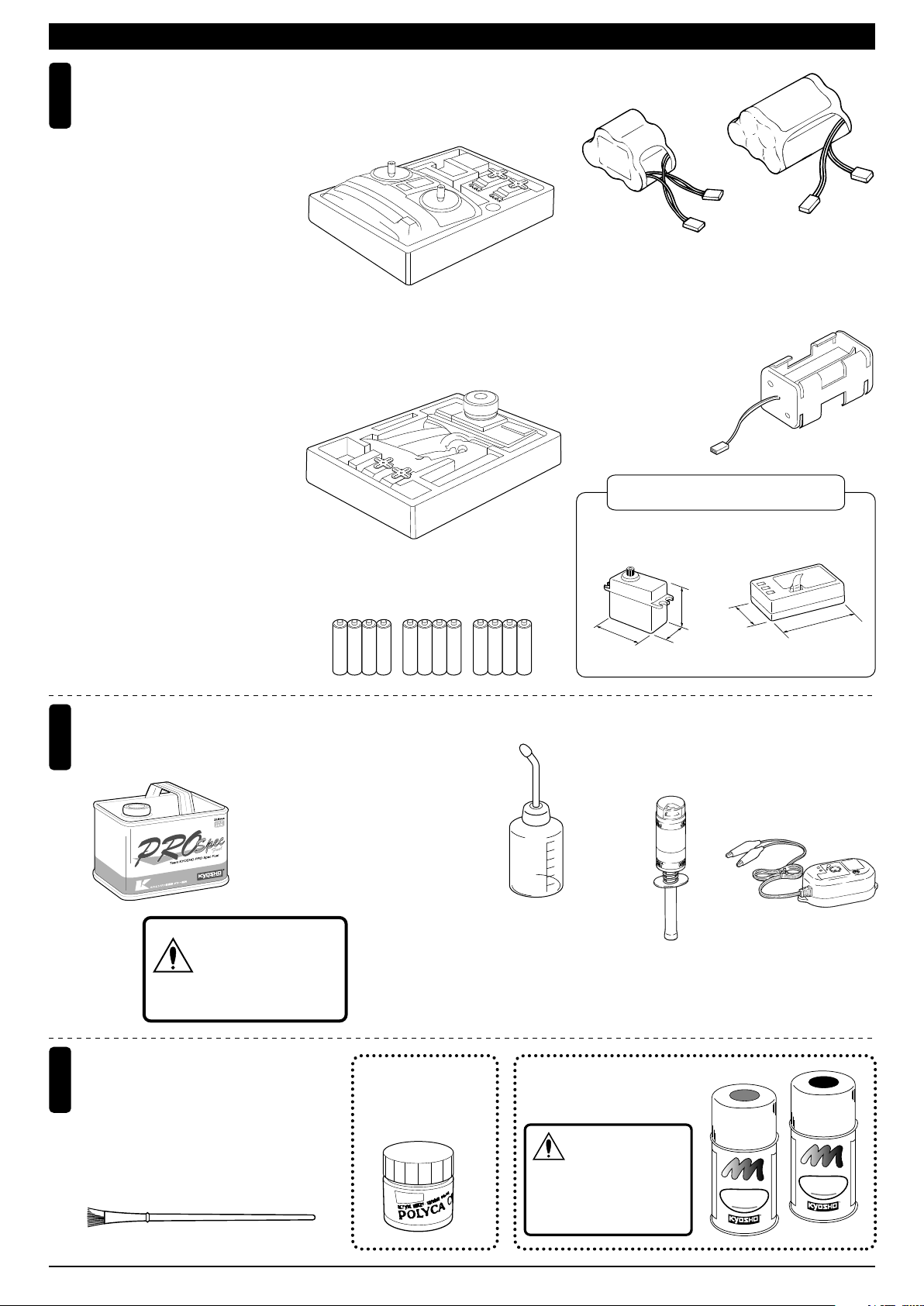
キットの他にそろえる物(1)REQUIRED FOR OPERATION (1)
2チャンネル2サーボ無線操縦機
1
(プロポ)
2ch radio control set with 2 servos.
●このキットには2チャンネル2サー
ボのプロポが必要です。
●送信機にはスティックタイプとハン
ドルタイプがありますが、お好みの
タイプを用意してください。
●リバース付プロポをご使用ください。
●プロポの取扱いは、プロポに付属の
説明書を参考にしてください。
●ステアリングサーボには、ハイトル
クタイプをご使用ください。
●This kit requires a 2 channel radio
con-trol set with 2 servos.
●Because there are stick-type and
wheel-type transmitters, use which
ever fits your convenience best.
●Use radio set with reverse function.
●For more information on the radio
con-trol set, refer to its instruction
manual.
●Use high torque servo for steering.
■スティックタイプ
2チャンネルプロポ
Stick-type
2ch radio set.
■ハンドルタイプ
2チャンネルプロポ
Wheel-type
2ch radio set.
■受信機用ニカドバッテリー
Battery for Receiver
No.71161
6V X-FORCE 600
ニカドバッテリー
Ni-Cd Battery
No.71211
6V X-FORCE 1100
ニカドバッテリー
Ni-Cd Battery
■電池ボックス
Battery Box
プロポセットに付いてい
●
るときは必要ありません。
If already included with
the radio, no battery box
needs to be pur-chased
separately.
使用できるサーボ・受信機サイズ
Suitable servos & receiver
模型用燃料と始動用具
Required for engine starting:
2
■燃料
Glow Fuel
警告
■単3乾電池(送・受信機用)
AA-size Batteries
(For Transmitter and Receiver)
No.73802
RCモデルフュール
プロスペックフュール(バギー用)
RC Model Fuel
PRO Spec Fuel (Buggy)
ガソリンや灯油は
使用禁止
WARNING: Gasoline
or kerosene cannot
be used.
AAAA AAAA AAAA
■燃料ポンプ
Fuel Pump
No.96422
クイックフュールポンプ
Quick Fill Fuel Bottle
■サーボ ■受信機
Servo Receiver
31〜36mm
39〜42mm
18〜20mm
29〜33mm
■プラグヒーター
Plug Heater
No.695142
DC急速充電器
No.695143
DC Quick Charger
スパークブースター
Spark Booster
43〜48mm
塗料/
筆
Paint / Paint
3
Brush
●ボディの塗装には塗料が必要です。
京商では、モデル用塗料、スプレー
を販売していますのでご利用ください。
●For painting the body, use Kyosho
paints for models!
2
ポリカカラー
POLYCA COLOR
No.76301〜76711No.2230
京商スプレーカラー
KYOSHO SPRAY COLOR
スプレーカラーを使用
する場合、缶の説明を
良く読んでください。
注意
CAUTION: Before using
Kyosho Spray Colors,
always read the
explanations!
F
U
E
L
T
P
R
N
O
I
O
A
F
P
K
O
Y
H
S
F
U
E
L
T
P
R
N
O
I
O
A
F
P
K
O
Y
H
S
O
S
P
R
O
R
L
A
O
Y
C
R
O
S
P
R
O
R
L
A
O
Y
C
R
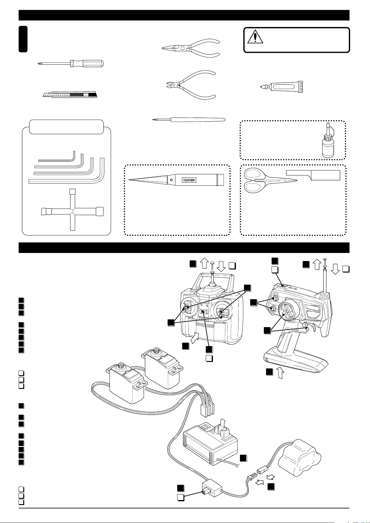
キットの他にそろえる物(2)REQUIRED FOR OPERATION (2)
組立てに必要な工具
Tools required
6
■+ドライバー(大、中、小)
Phillips Screwdriver (L.M.S)
■カッターナイフ
Sharp Hobby Knife
キットに入っている工具
TOOLS INCLUDED
■六角レンチ(1.5mm,2mm,2.5mm,3mm)
Hex Wrench (1.5mm, 2mm, 2.5mm, 3mm)
■十字レンチ(大)
Cross Wrench
■ラジオペンチ
Needle Nose Pliers
■ニッパー
Wire Cutters
■キリ
Awl
No.695101
ナイフエッジリーマー
KNIFE EDGE REAMER
下穴加工が不要で、直接
1mm〜15mmの正確な穴
あけができる工具です。
No need to pre-drill!
Drills neat 1mm to 15mm
holes directly!
使用する工具の取扱いには、
十分注意してください。
CAUTION: Handle tools carefully!
注意
■ネジロック剤
Screw Cement
ネジロック剤
KYOSHOスペシャルグルー
KYOSHO Special Glue
瞬間接着剤
Instant Glue
No.1829
ラウンドカッター&サンダー
ROUND CUTTER & SANDER
ボディのカット、仕上
げ用。曲線部分も楽に
作業ができます。
No.96154
KYOSHO
Special Glue
For trimming bodies!
Cutting along curved lines
never was so easy!
プロポの準備 RADIO PREPARATION
●プロポを下の順番にしたがってセットします。
Set up the radio control system as indicated below.
●始める時
1
送信機に単3乾電池をセットす
る。
2
送信機のアンテナをのばす。
3
電充 電し た受信 機用ニカド バ
ッテリーをつなぐ。
4
受信機のアンテナをのばす。
5
トリムを中央にセットする。
6
送信機のスイッチを入れる。
7
受信機のスイッチを入れる。
8
ハンドル/トリガー を動かして
●終わる時
9
受信機のスイッチを切る。
10
送信機のスイッチを切る。
11
送信機のアンテナを縮める。
●START
1
Insert AA-size batteries into
the Transmitter.
2
Extend the Transmitter aerial.
3
Connect the charged Ni-Cd
battery to the receiver.
4
Unwind the Receiver aerial.
Center the Transmitter trims.
5
Switch "ON" the Transmitter.
6
Switch "ON" the Receiver.
7
Make sure the servos move
8
according to your transmitter
inputs.
●FINISH
9
Switch "OFF" the Receiver.
10
Switch "OFF" the Transmitter.
11
Retract the Transmitter aerial.
サーボ▼
Servo
Transmitter
送信機
▲
5
ON
OFF
ON
2
11
10
6
OFF
2
11
8
5
8
1
10
ON
6
OFF
1
▼受信機
Receiver
4
▼スイッチ
Switch
7
3
▲バッテリー
Battery
9
3
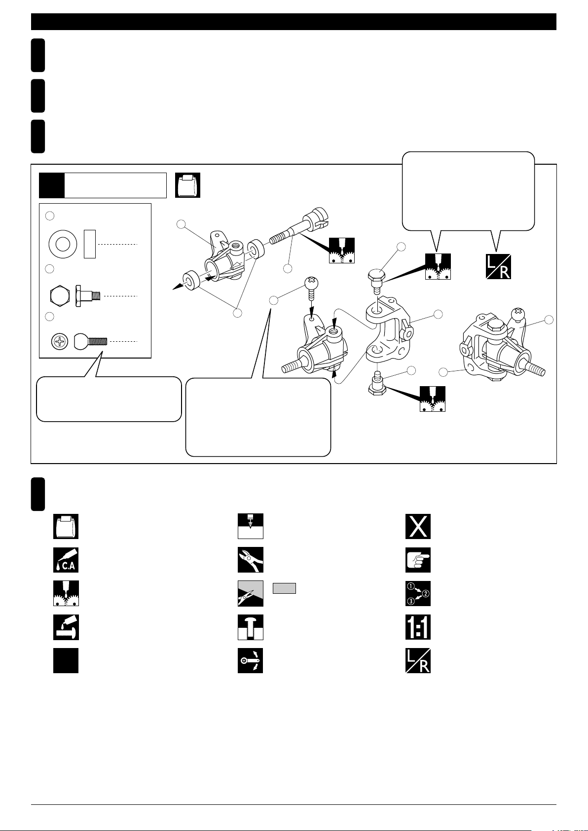
組立て前の注意(1) BEFORE YOU BEGIN (1)
組立てる前に説明書を良く読んで、おおよその構造を理解してから組立てに入ってください。
1
Read through the manual before you begin, so you will have an overall idea of what to do.
キットの内容をお確かめください。万一不良、不足がありましたら、お買い求めの販売店にご相談いただくか、当社「ユーザー相談室」までご連絡ください。
2
Check all parts. If you find any defective or missing parts, contact your local dealer or our Kyosho Distributor.
説明書の見かた
3
How to read the instruction manual:
〔説明例Example〕
説明書内では多くのマークが使用
フロントサスペンション
Front Suspension
1
4
5 x 10mm メタル
Metal Bushing
No.4, No.5, No.6
1
されています。マークに注意して
組立てを進めてください。
This instruction manual uses several symbols. Please note them
during the entire assembly.
4
キングピン
5
King Pin
4
5.8mm ピロボール(黒)
6
Pillow Ball (Black)
2
小物部品の名前、原寸図、使用数。
Key Number, Part Name, True-to-scale
Diagram, Quantity Used
説明書に使われているマーク
4
Symbols used throughout the instruction manual, comprise:
使用する袋詰。
Part bags used.
キット内の部品は、ビス類を除いてキー
No.が付けられています。スペアパーツを
購入する時はキーNo.を参照して下さい。
All parts except screws are identified by
key numbers. For purchasing spare parts,
find the key no. of the part needed in the
spare part list and refer to the left column
to look up the corresponding order no.
4
2mm
3
6
2mmの穴をあける(例)。
Drill holes with the specified
diameter (here: 2mm).
5
7
R
L
5
8
別購入品
Must be purchased separately!
2
x2
瞬間接着剤で接着する。
Apply instant glue (CA glue, super glue).
グリスを塗る。
Apply grease.
ネジロック剤を塗る。
Apply threadlocker (screw cement).
2セット組立てる(例)。
Assemble as many times as
specified (here: twice).
余分をカットする。
Cut off excess.
をカットする。
Cut off shaded portion.
仮止め。
Tentatively tighten.
可動するように組立てる。
Ensure smooth non-binding
movement while assembling.
注意して組立てる所。
Pay close attention here!
番号の順に組立てる。
Assemble in the specified
order.
原寸図
True-to-scale diagram.
左右同じように組立てる。
Assemble left and right sides
the same way.
4
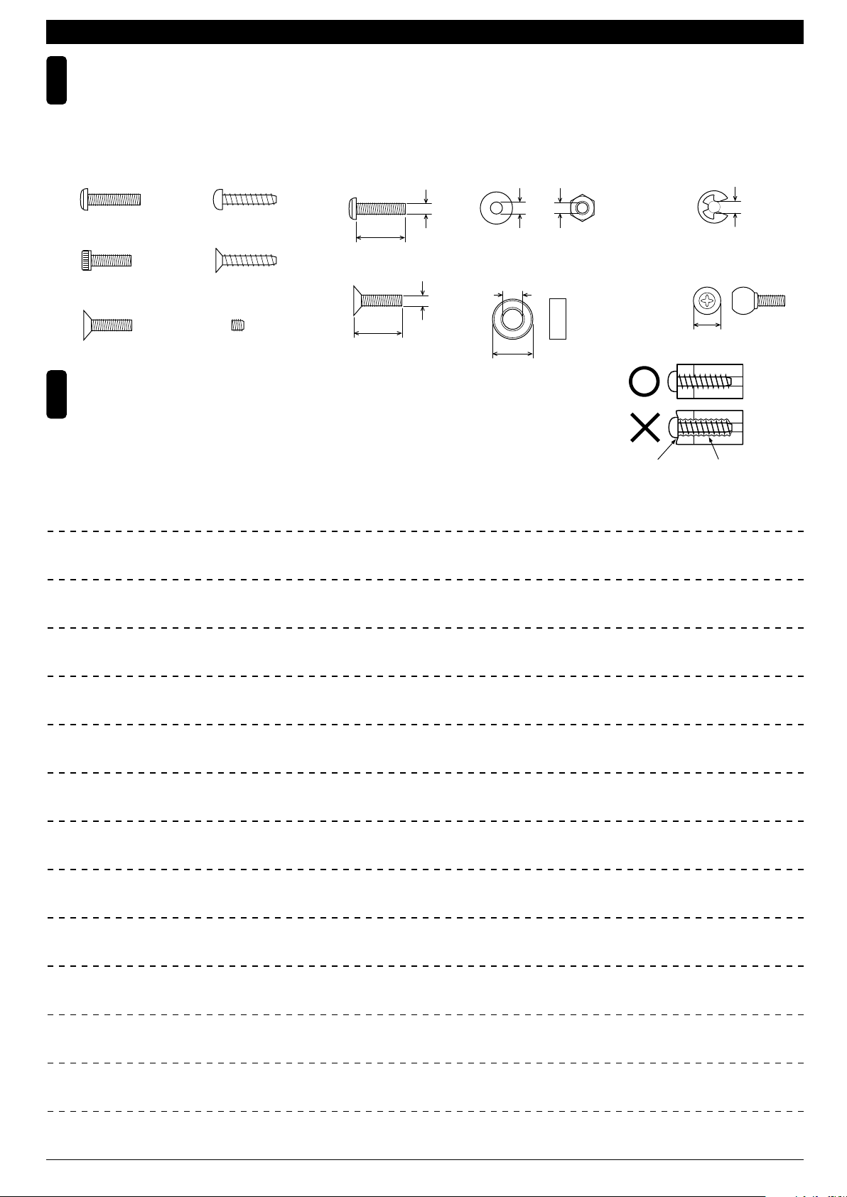
組立て前の注意(2) BEFORE YOU BEGIN (2)
キットには、形や長さが違うビスや小物部品が多く入っています。説明書には原寸図がありますので確認してから組立ててください。
5
また、ビス類は多めに入っているものもありますので、予備としてお使いください。
This kit contains screws and hardware in different metric sizes and shapes.
Before using them, check the screws on the true-to-scale diagrams on the left side in each assembly step. Some screws are extras.
●ビスの種類 SCREWS
ビス Screw
キャップビス
Cap Screw
サラビス
Flat Head (F/H) Screw
TPビスは、部品にネジを切りながらしめつけるビスです。しめこみが固い場合がありますが、
6
部品が確実に固定されるまでしめこんでください。ただし、しめすぎるとネジがきかなくなり
ますので、部品が変形するまでしめないでください。
Self-tapping (TP) screws cut threads into the parts when being tightened. Excessive force may
permanently damage parts when tightening TP screws. It is recommended to stop tightening when
the part is attached or when some resistance is felt after the threaded portion enters the plastic.
TPビス
Self-tapping (TP) Screw
TPサラビス
TP F/H Screw
セットビス
Set Screw
●小物部品のサイズ例 OTHER HARDWARE
3x12mmビス
Screw
12mm
3x12mmサラビス
F/H Screw
3mm
12mm
3mmワッシャー・ナット
Washer・Nut
3mm
5x10mmメタル・ベアリング
Metal Bushing・Bearing
5mm
10mm
MEMO
3mm
Correct
Wrong
しめすぎ
Overtightened.
E3Eリング
E-ring
3mm
6.8mmピロボール
Pillow Ball
6.8mm
ビスがきかない
The threads are stripped.
5
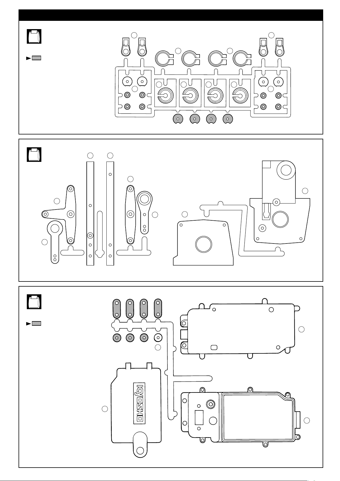
ランナー付プラパーツ配置図(1)/
ARRANGEMENT OF PLASTIC PARTS ON RUNNERS (1)
No.2
部の部品は使用しません。
Shaded parts are not used.
No.3
97 98
54 54
56
55 55
146
57
57 57 57
56
85
147
77
No.5
部の部品は使用しません。
Shaded parts are not used.
78
84
99
102
101
100
6
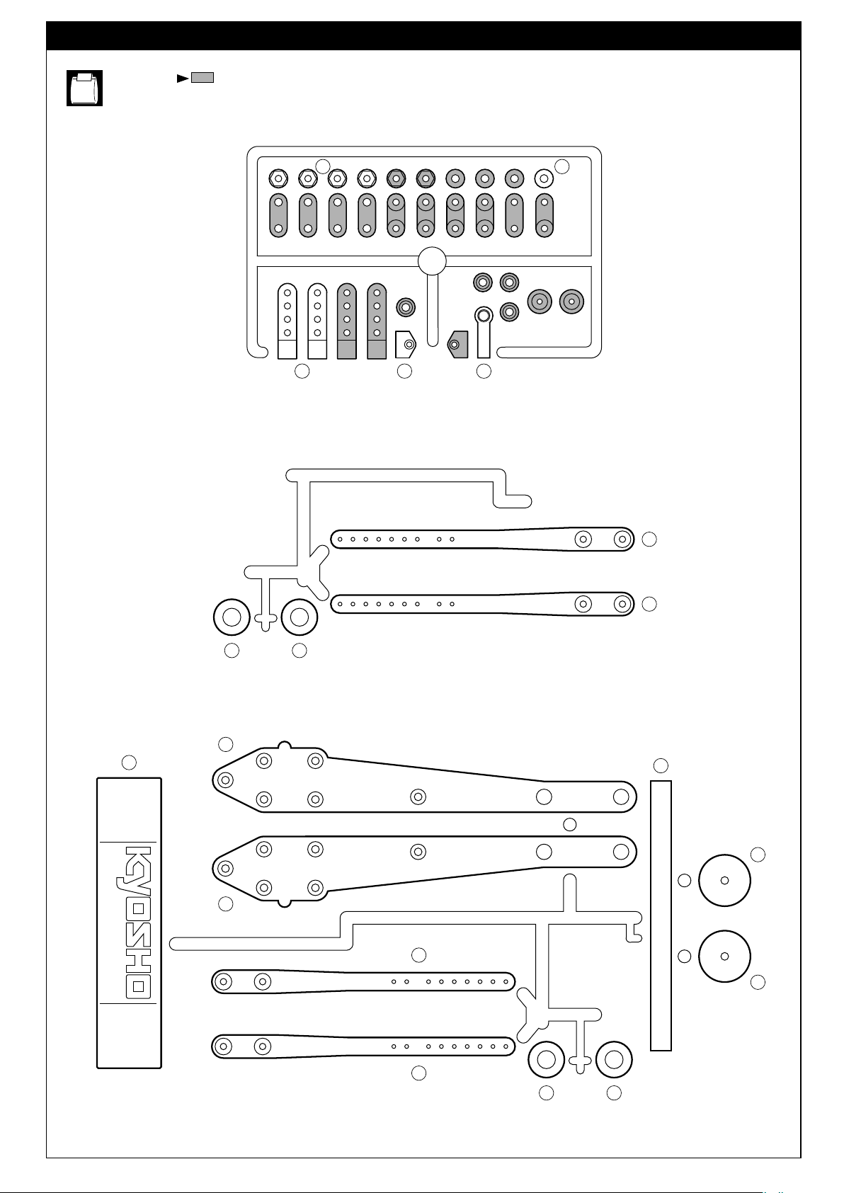
ランナー付プラパーツ配置図(2)/
ARRANGEMENT OF PLASTIC PARTS ON RUNNERS (2)
No.6
部の部品は使用しません。
Shaded parts are not used.
130148
129106
128
110
115
116
112
111
111
112
114
117
111
111
117
112 112
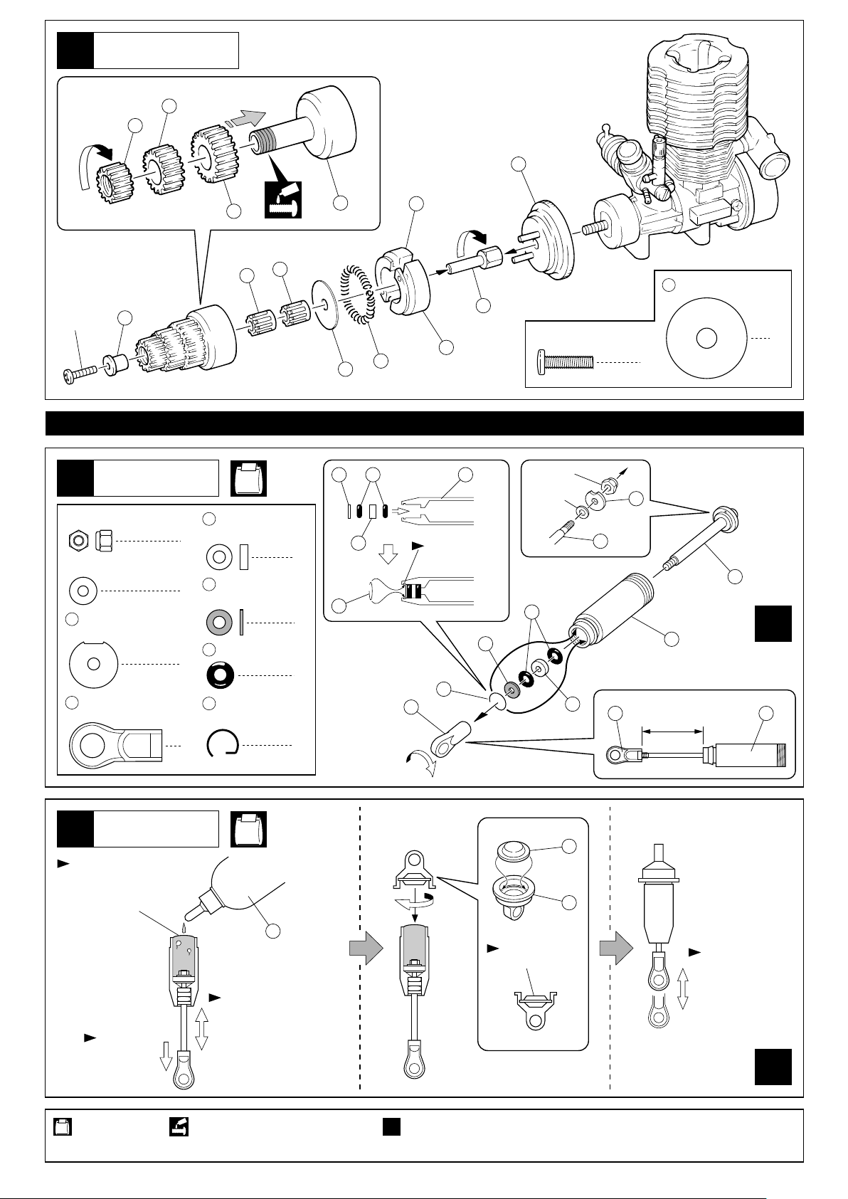
7
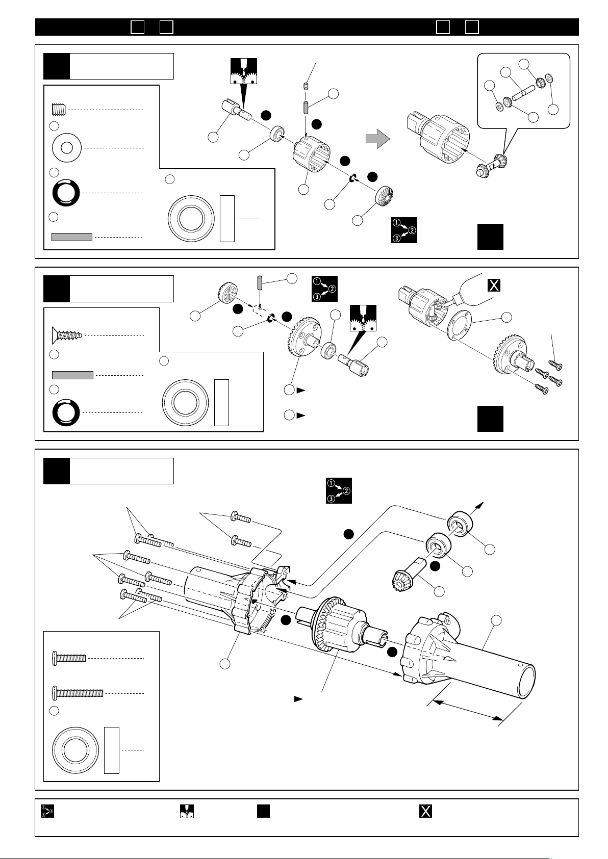
〜は組立済です。
1 8
Parts are pre-assembled in step ~ .
1 8
デフギヤ
Gear Differential
1
4 x 4mm
Set Screw
11
6 6mm
4 2.6 x 14mm
2
3 x 10mm
TP F/H Screw
4 2.6 x 14mm
6 6mm
セットビス
4 x 10mm
Shim
O-ring
Shaft (Black)
Shaft (Black)
O-ring
シム
Oリング
シャフト(黒)
デフギヤ
Gear Differential
TPサラビス
シャフト(黒)
Oリング
2
4
5 8 x 16mm
Ball Bearing
2
2
2
8
5 8 x 16mm
Ball Bearing
2
2
8
5
ベアリング
2
6
ベアリング
4x4mm
10
9
11
4
1
3
10
11
2
4
1
6
2
2
フロント/リヤ用
For front and rear
x2
4
1
5
8
12
フロント用(アルミ製、銀色)
2
For Front (Aluminium, Silver)
リヤ用(スチール製、黒色)
3
For Rear (Steel, Black)
デフオイル
Diff. Oil
15
3x10mm
フロント/リヤ用
For front and rear
x2
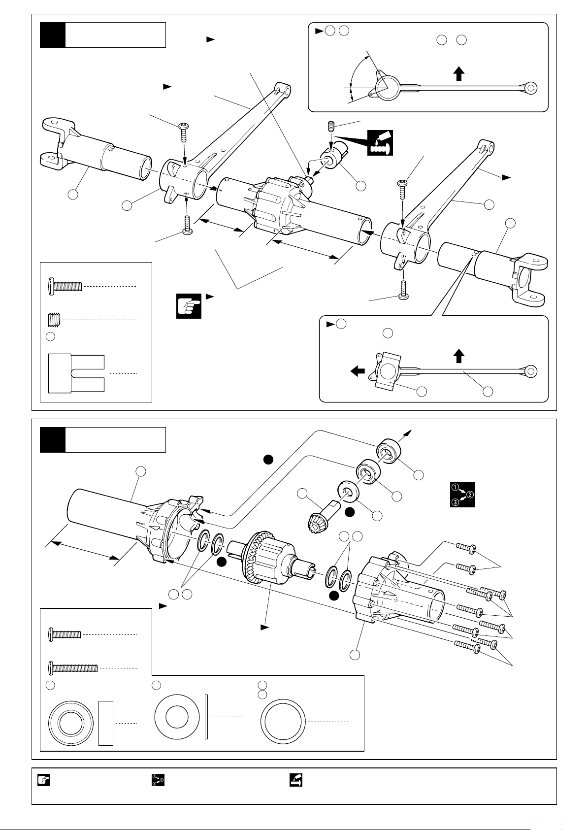
フロントアクスル
Front Axle
3
2.6x16mm
2.6x16mm
2.6x16mm
2.6 x 10mm
Screw
2.6 x 16mm
Screw
5 8 x 16mm
Ball Bearing
ビス
ビス
ベアリング
2.6x10mm
2
7
2
13
短い方
Short
1
フロント用
For Front
3
5
2
5
7
14
4
長い方
Long
x2
2セット組立てる(例)。番号の順に組立てる。 グリスを塗る。
Assemble as many times as specified.Assemble in the specified order. Apply grease.
別購入品。
Must be purchased separately!
8
フロントサスアーム
Front Suspension Arm
4
19
3x10mm
17
Aのマーク
Marked ÒAÓ
平らな面にセットビス
を固定する。
Install a setscrew on
the flat surface.
, は向きに注意。
17 18
Pay attention to the direction of & .
広い
Wide
狭い
Narrow
5x4mm
17 18
3x10mm
157
上
Up
B
Bのマーク
Marked ÒBÓ
18
3 x 10mm
Screw
5 x 4mm
Set Screw
157
ジョイントカップ(L)
Joint Cup (L)
ビス
セットビス
リヤアクスル
Rear Axle
5
3x10mm
4
1
1
14
短い方
Short
長さに注意。
Pay attention to the lengths.
3
長い方
Long
23
3x10mm
が図の角度になるように固定穴に注意する。
19
The angle of must be as shown in the drawing.
Use the correct hole.
前
Front
19
上
Up
1819
5
5
1
20
19
21 22
長い方
Long
21 22
枚数を変えて、バック
2.6 x 10mm
Screw
2.6 x 16mm
Screw
5 8 x 16mm
Ball Bearing
注意して組立てる所。 番号の順に組立てる。
Pay close attention here! Assemble in the specified order. Apply threadlocker (screw cement).
ビス
ビス
ベアリング
ラッシュを調整する。
Adjust the backlash
with the shims.
2
7
8 x 16 x 1mm
20
Washer
2
2
4
リヤ用
For Rear
13
ワッシャー シム(厚 Thick)
212213 x 16mm
Shim
1
シム(薄 Thin)
1
ネジロック剤を塗る。
短い方
Short
2.6x10mm
2.6x16mm
2.6x16mm
2.6x16mm
9

リヤサスアーム
Rear Suspension Arm
6
3x10mm
Aのマーク
Marked ÒAÓ
平らな面にセットビス
を固定する。
Install a setscrew on
the flat surface.
, は向きに注意。
17 18
Pay attention to the direction of & .
広い
Wide
狭い
Narrow
5x4mm
17 18
上
Up
19
3 x 10mm
Screw
5 x 4mm
Set Screw
157
ジョイントカップ(L)
Joint Cup (L)
ビス
セットビス
3スピードミッション
3 Speed Changer
7
3 x 6mm
Screw
4 x 4mm
Set Screw
24
25
6 x 13mm
Washer
ビス
セットビス
4 x 4mm
Lock Set Screw
6 x 12 x 4mm
Ball Bearing
ロックセットビス
ベアリング
ワッシャー
17
3x10mm
4
1
1
28
10 x 15mm
Ball Bearing
4
2
2912 x 9.8mm
Pin
2
1
2
長い方
Long
長さに注意。
Pay attention
to the lengths.
ベアリング
1
ピン
シャフトの溝
Groove of shaft.
28
3x10mm
157
短い方
Short
3x10mm
が図の角度になるように固定穴に注意する。
19
The angle of must be as shown in the drawing.
Use the correct hole.
19
上
Up
1819
24
31
32
32
33
30
4x4mm
25
38
37
27
36
6x13mm
24
34
B
18
19
前
Front
29
35
シャフトの溝にセット
ビスが入るように締める。
Install with a setscrew on
the groove of the shaft.
Bのマーク
Marked ÒBÓ
36
30
37
26
6 x 10 x 3mm
Metal Bushing
27
6 x 12 x 4mm
Metal Bushing
メタル
メタル
1
4x4mm
3
42
ネジロック剤を塗る。 注意して組立てる所。仮止め。
Apply threadlocker (screw cement). Pay close attention here!Tentatively tighten.
10
26
41
40
3x6mm
3x6mm
27
6x13mm
27
39
8
エンジン
Engine
51
52
43
3x12mm
9
2.6mm
Nylon Nut
2.6mm
Washer
55
54
53
ダンパー
Shock
ナイロンナット
ワッシャー
ピストン
Piston
6.8mm
ボールエンド(S)
Ball End (S)
61
4
62
4
60
4
63
50
48
48
No.2
カラー(白)
Collar (White)
カラー(黒)
Collar (Black)
3mm
Oリング
O-ring
Cリング
C-ring
49
47
組み立て開始
60
61
4
46
45
45
START
5962
溝にはめる。
Fit into groove.
44
3 x 12mm
Screw
2.6mm
2.6mm
ビス
58
55
47
5 x 20mm
Shim
1
シム
1
58
63
4
62
8
60
59
x4
63
54
61
約38mm
54 59
approx. 38mm
ダンパー
Shock
10
多少もり上がる
ぐらいまで入れる。
Fill in until shock oil
nearly overflows.
ピストンを
下げる。
Pull down
the piston.
使用する袋詰。
Part bags used.
4
4
No.2
ダンパーオイル
Shock Oil
66
奥まで入れる。
Insert deeply.
上下させ、気泡をとる。
Then, gently move the
piston up and down to
get rid of air bubbles.
ネジロック剤を塗る。 4セット組立てる(例)。
Apply threadlocker (screw cement).
x4
Assemble as many times as specified.
64
65
スムーズに動くか
確認する。
Check if piston
moves smoothly.
x4
11
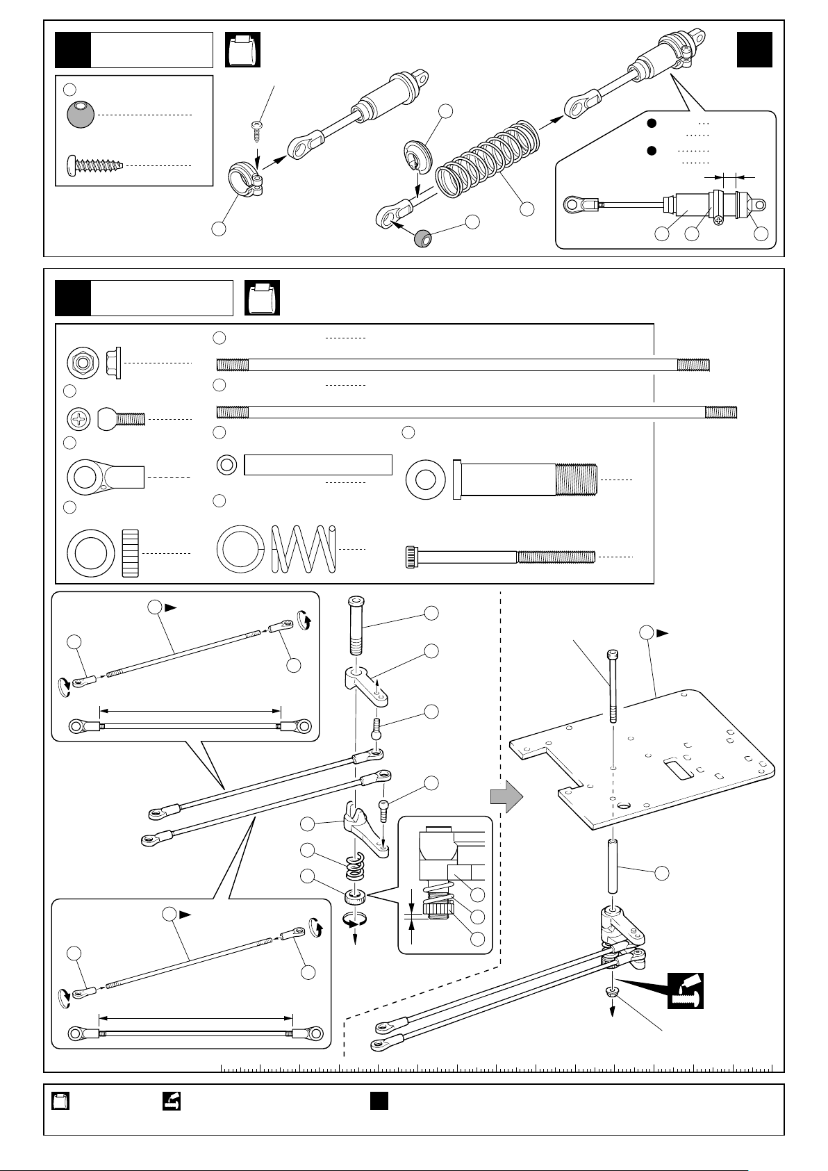
ダンパー
Shock
11
67
6.8mm
ボール(黒)
Ball (Black)
3 x 12mm
TP Screw
TPビス
No.2
3x12mm
4
4
57
x4
約6mmフロント
approx. 6mmFront
約10mmリヤ
approx. 10mmRear
サーボセイバー
Servo Saver
12
3mm
フランジ付ナット
Flanged Nut
5.8mm
69
70
72
ピロボール(銀)
Pillow Ball (silver)
5.8mm
ボールエンド
Ball End
セイバーナット
Saver Nut
75
70
56
75
3 x 125mm
Rod
1
76
3 x 132mm
Rod
2
73
5 x 37.5mm
Shaft
2
71
サーボセイバースプリング
Servo Saver Spring
1
短い方
Short
約115mm
approx. 115mm
67
No.1, No.3
ロッド
ロッド
シャフト セイバーシャフト
1
1
74
Saver Shaft
1
3 x 45mm
Cap Screw
1
キャップビス
74
77
70
69
68
3x45mm
59 56 65
1
1
79
向きに注意。
Note the direction.
70
使用する袋詰。
Part bags used.
12
69
78
71
72
76
長い方
Long
2mm
70
約123mm
approx. 123mm
ネジロック剤を塗る。 4セット組立てる(例)。
Apply threadlocker (screw cement).
x4
Assemble as many times as specified.
73
78
71
72
3mm
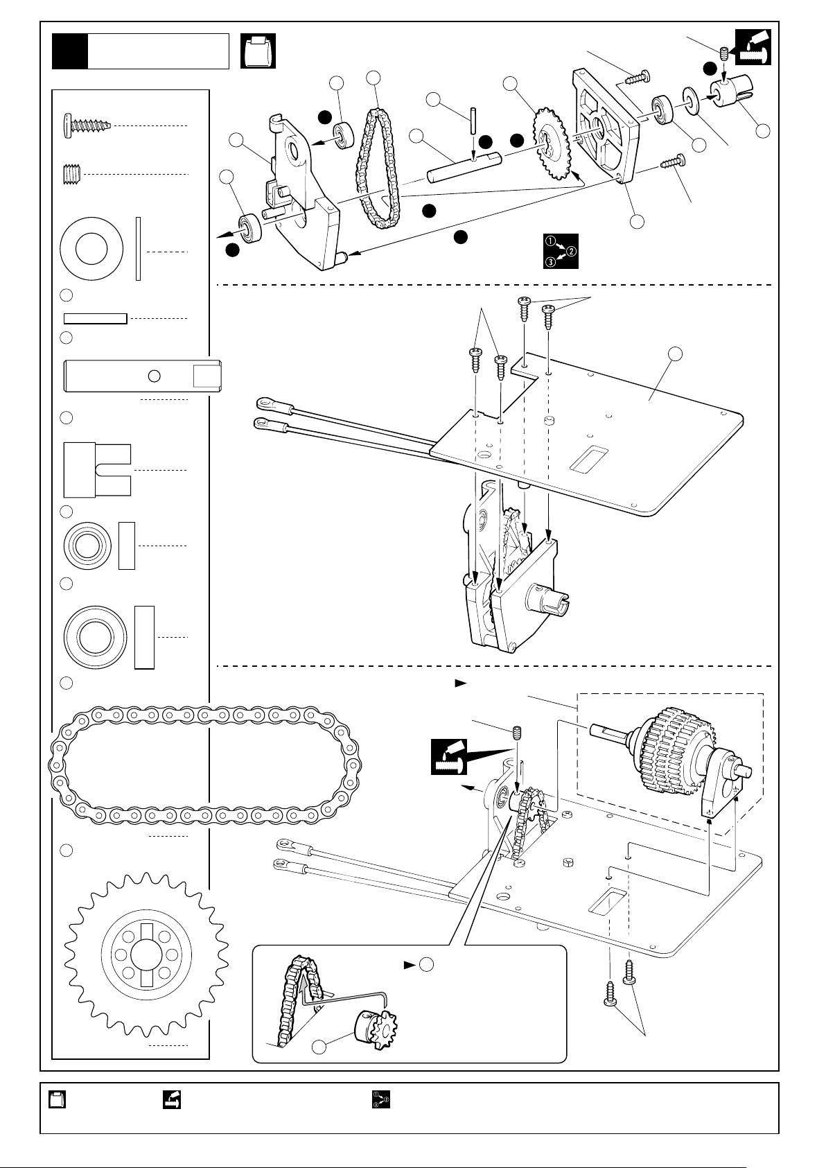
ギヤボックス
Gearbox
13
3 x 10mm
TP Screw
5 x 4mm
Set Screw
8 x 16mm
Washer
80
2.6 x 16mm
Pin
81
センターシャフト
Center Shaft
16
ジョイントカップ
Joint Cup
TPビス
セットビス
ワッシャー
ピン
5x4mm
No.1, No.3
25
82
3x10mm
3
83
80
8
85
1
5
7
81
2
1
4
84
5
ワッシャー
Washer
3x10mm
16
8x16mm
5
1
6
3x10mm
1
3x10mm
79
1
25
6 x 12 x 4mm
Ball Bearing
5
8 x 16mm
Ball Bearing
ドライブチェーン
82
Drive Chain
26T
スプロケット
83
Sprocket
ベアリング
ベアリング
1
1
2
組立済。
Assembled.
4x4mm
1
使用する袋詰。
Part bags used.
1
ネジロック剤を塗る。
Apply threadlocker (screw cement).
42
11Tスプロケットを一度
42
外し、チェーンに引っかけ
てから再度組み立てる。
Remove the 11T sprocket
and hook on the drive chain.
Then, reattach the sprocket.
番号の順に組立てる。
Assemble in the specified order.
3x10mm
13
 Loading...