

Page 1
※ご使用前にこの説明書を良くお読みになり十分に理解してください。
Before beginning assembly, please read these instructions thoroughly.
R
THE FINEST RADIO CONTROL MODELS
ELECTRIC
POWER
組立/取扱説明書
EPVERSION
INSTRUCTION MANUAL
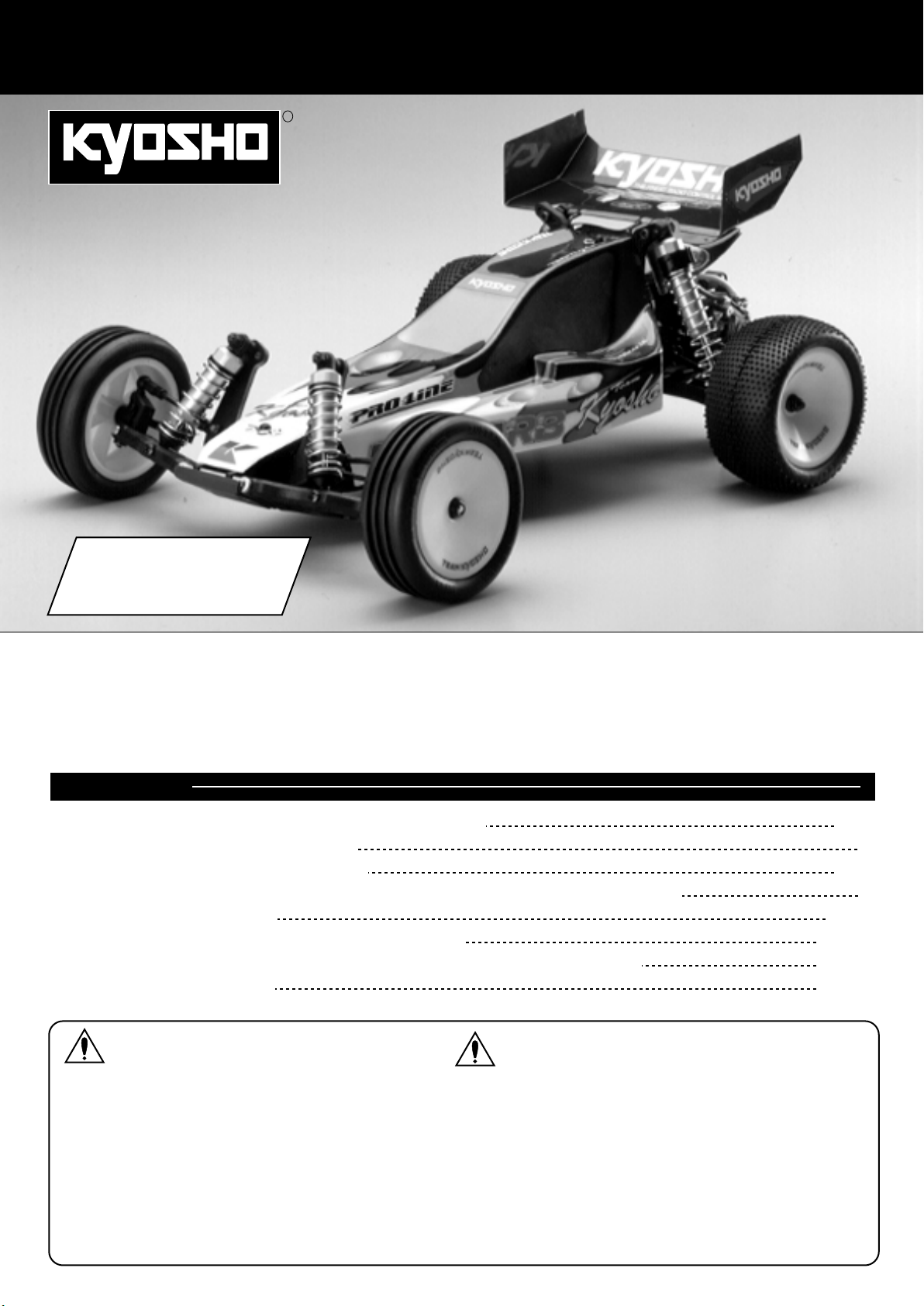
1:10 SCALE RADIO CONTROLLED ELECTRIC POWER 2WD RACING BUGGY
EP ULTIMA RB Type-R EVOLUTION
目 次 INDEX
●キットの他にそろえる物 REQUIRED FOR OPERATION
●プロポの準備 RADIO PREPARATION
●組立て前の注意 BEFORE YOU BEGIN
●ランナー付プラパーツ配置図 ARRANGEMENT OF PLASTIC PARTS ON RUNNERS
●本体の組立て ASSEMBLY
●取扱いの注意 OPERATING YOUR MODEL SAFELY
●スペアパーツ・オプションパーツリスト SPARE PARTS & OPTIONAL PARTS
●分解図 EXPLODED VIEW
2〜3
3
4〜5
5
6〜22
23〜26
27〜29
30〜31
安全のための注意事項
UNDER SAFETY PRECAUTIONS
This radio control model is not a toy.この無線操縦模型は玩具ではありません!
●この商品は高い性能を発揮するように設計されています。
組立てに不慣れな方は、模型を良く知っている人にアド
バイスを受け確実に組立ててください。
●小さい部品があるので、組立て作業は、幼児の手がとど
かない所で必ず行ってください。
●動かして楽しむ場所は万一の事故を考えて、安全を確認
してから責任をもってお楽しみください。
●組立てた後も、説明書がいつでも見られるように大切に
保管してください。
※製品改良のため、予告なく仕様を変更する場合があります。 SPECIFICATIONS ARE SUBJECT TO BE CHANGED WITHOUT NOTICE.
© 2003 KYOSHO CORPORATION/禁無断転載複製
●First-time builders should seek the advice of experienced modellers
before beginning assembly and if they do not fully understand any
part of the construction.
●Assemble this kit only in places out of children's reach!
●Take enough safety precautions prior to operating this model.
You are responsible for this model's assembly and safe operation!
●Always keep this instruction manual ready at hand for quick
reference, even after completing the assembly.
No.30073 / 30073B
Page 2
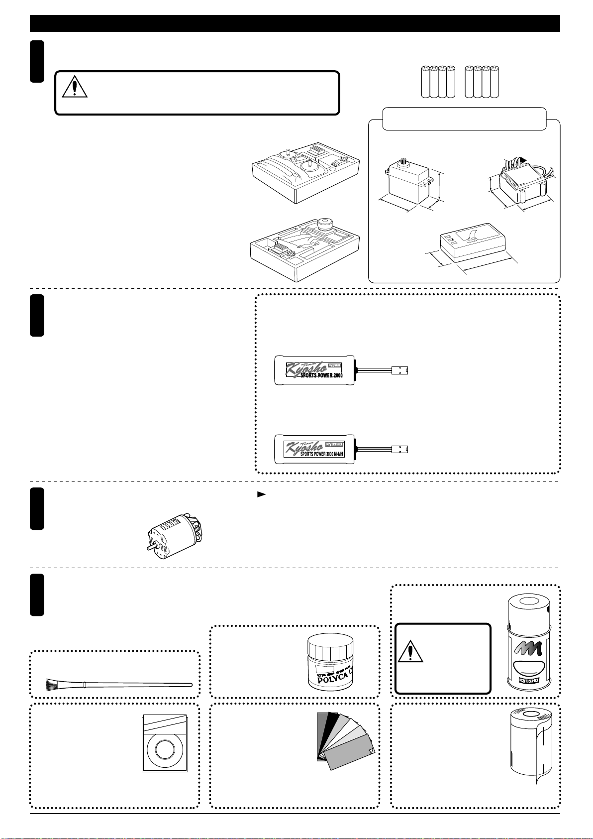
REQUIRED FOR OPERATION (1)キットの他にそろえる物(1)
2チャンネルアンプ仕様無線操縦機(プロポ)と電池
1
2ch with electronic speed controller and 1 servo radio control set
地上用(自動車用)のプロポ(2チャンネルアンプ仕様)セットを
必ず使用してください。(地上用以外使用禁止)
CAUTION: Only use a surface radio with 2 channels and electronic
注意
speed controller! (Any other radio is prohibited!)
●このキットには2チャンネルアンプ仕様
のプロポが必要です。
●送信機にはスティックタイプとハンドル
タイプがありますが、お好みのタイプを
■スティックタイプ
2チャンネルプロポ
Stick-type
2ch radio set
用意してください。
●プロポの取扱いは、プロポに付属の説明
書を参考にしてください。
●This kit requires a 2 channel radio con-
trol set with electronic speed controller.
●Because there are stick-type and wheeltype transmitters, use which ever fits
■ハンドルタイプ
2チャンネルプロポ
Wheel-type
2ch radio set
your convenience best.
●For more information on the radio con-trol
set, refer to its instruction manual.
走行+受信機用バッテリー、バッテリー充電器
2
Operation/Receiver Battery
and Charger for Ni-Cd Battery
●バッテリーは、1個で車の走行と受信機の電源として
使います。右のバッテリーが純正バッテリーです
のでいずれかを使用してください。
●バッテリー用充電器には、12Vカーバッテリーから
おこなう急速充電器と、家庭のコンセント(100V)
からおこなう急速充電器の2タイプがあります。
A single Ni-Cd battery powers operation and receiver. Batteries listed right are suitable.
Two types of chargers are available. One operates
on a 12V car battery. The other operates on a 100V
house outlet.
■単3乾電池(送信機用)
AA-size Batteries (For Transmitter)
AAAA
使用できるサーボ・受信機・アンプサイズ
Suitable servos, receiver & electric speed controller
■サーボ
Servo
31〜36mm
38〜41mm
■受信機
Receiver
No.71901
■7.2Vスポーツパワー2000バッテリー
(入門タイプ)
7.2V Sports Power Battery
(Beginner class)
RECHARGEABLE Ni-Cd BATTERY
KYOSHO CORPORATION NO.71901
No.71221
■7.2Vスポーツパワー3000ニッケル水素バッテリー
7.2V SPORTS POWER 3000 Ni-MH Battery
RECHARGEABLE Ni-MH BATTERY
No.71221
18〜20mm
29〜32mm
No.72021
■XチャージャーAC
No.72101
■エクセルプロチャージャー
AAAA
■アンプ
Electric speed controller
20〜29mm
31〜40mm
36〜43mm
43〜48mm
X-CHARGER AC
EXCEL PRO CHARGER
3
モーター
Motor
●540サイズを用意してください。
540 size motor sold separately.
塗料と筆
4
Paint and Brush
●ボディの塗装には塗料が必要です。
京商では、モデル用塗料、スプレーを
用意していますのでご利用ください。
For painting the body, use Kyosho paints
for models!
■筆
PAINT BRUSH
ミクロンラインテープ
MICRON LINE TAPE
No.1841
マスキング、細部デザイ
ン用伸縮自在テープです。
1842
1843
1859
1860
(1mm x 5m)
(1.5mm x 5m)
(2.5mm x 5m)
(0.4mm x 8m)
(0.7mm x 8m)
Super-flexible tape for
masking and detail designing jobs.
キット標準のギヤ比は、11T(ターン)モーターに対応しています。
Kit gear ratio for use with 11 turn motor.
No.76301〜76711
京商スプレーカラー
KYOSHO SPRAY COLOR
注意
スプレーカラーを
使用する場合、缶
の説明を良く読ん
でください。
CAUTION: Before
using spray colors,
always read their
explanations!
E
N
L
P
R
I
O
A
F
P
F
U
T
F
K
O
Y
H
S
O
S
P
R
O
R
L
A
O
Y
C
R
No.2230
ポリカカラー
POLYCA COLOR
pe
Ta
e
n
Li
cron
i
M
KYOSHO
No.96701
D‑フレックスカラーデカール
D FLEX COLOR DECAL
伸縮自在の特殊素材で3次曲面
にもきれいに貼れる粘着シートです。
Self-adhesive super-flexible sheets that
bond to polycarbonate - even when
applied to curved surfaces.
No.1947
マスキングカバーシート
MASKING SHEET
マスキングテープとビニール
シートが一体になった広範囲
マスク用テープです。
For safe masking jobs, use this plastic masking sheet featuring one self-adhesive edge.
2
Page 3
REQUIRED FOR OPERATION (2)キットの他にそろえる物(2)
組立てに必要な工具
Tools required
5
■+ドライバー(大、中、小)
Phillips Screwdriver ( L. M. S. )
■カッターナイフ
Sharp Hobby Knife
■キリ
Awl
キットに入っている工具
TOOLS INCLUDED
■六角レンチ
Hex Wrench
■十字レンチ
Cross Wrench
■ボールデフグリス
Ball Differential Grease
■ラジオペンチ
Needle Nose Pliers
■ニッパー
Wire Cutters
ナイフエッジリーマー
KNIFE EDGE REAMER
下穴加工が不要で、直接1mm〜15mmの穴あけ
ができる工具です。
No need to pre-drill!
Drills neat 1mm to 15mm holes directly!
■ダンパー用シリコンオイル
Silicone Oil (for Shock)
No.695101
使用する工具の取扱いには、十分
注意してください。
CAUTION: Handle tools carefully!
注意
■モリブデン系グリス
Molybdenum Grease
KYOSHOスペシャルグルー
KYOSHO Special Glue
瞬間接着剤
Instant Glue
No.1829
ラウンドカッター&サンダー
ROUND CUTTER & SANDER
ボディのカット、仕上
げ用。曲線部分も楽に
作業ができます。
Grease
No.96154
KYOSHO
Special Glue
For trimming bodies!
Cutting along curved lines
never was so easy!
プロポの準備 RADIO PREPARATION
●キットの組立てに入る前に、ニカドバッテリーを充電器の説明にしたがって充電しておきます。
A new Ni-Cd battery must be charged before it is used. Refer to the charger instruction manual for charging.
●プロポを下の順番にしたがってセットします。
Set up the radio control system as indicated below.
▲ニカドバッテリー
Ni-Cd Battery
ON
6
10
OFF
2
11
2
5
8
5
3
11
8
送信機
▲
Transmitter
1
ON
1
6
10
OFF
▲充電器
Charger
▲サーボ
Servo
▼アンプ
Electronic Speed Controller
▲受信機
Receiver
▲スイッチ
Switch
4
ON
7
9
OFF
●始める時
●終わる時
1
単3乾電池をセットする。(送信機)
アンテナをのばす。(送信機)
2
ニカドバッテリーをつなぐ。
3
アンテナをのばす。(受信機)
4
トリムレバーを中央にセットする。
5
スイッチを入れる。(送信機)
6
スイッチを入れる。(受信機)
7
スティックを動かしてサーボが動くか確認する。
8
9
スイッチを切る。(受信機)
10
スイッチを切る。(送信機)
11
アンテナを縮める。(送信機)
●START
●FINISH
Install batteries. (Transmitter)
1
Extend the antenna. (Transmitter)
2
Connect the Ni-Cd battery.
3
Extend the antenna. (Receiver)
4
Center the trims.
5
Switch on. (Transmitter)
6
Switch on. (Receiver)
7
Make sure the servos are in command.
8
Switch off. (Receiver)
9
Switch off. (Transmitter)
10
Retract the antenna. (Transmitter)
11
3
Page 4
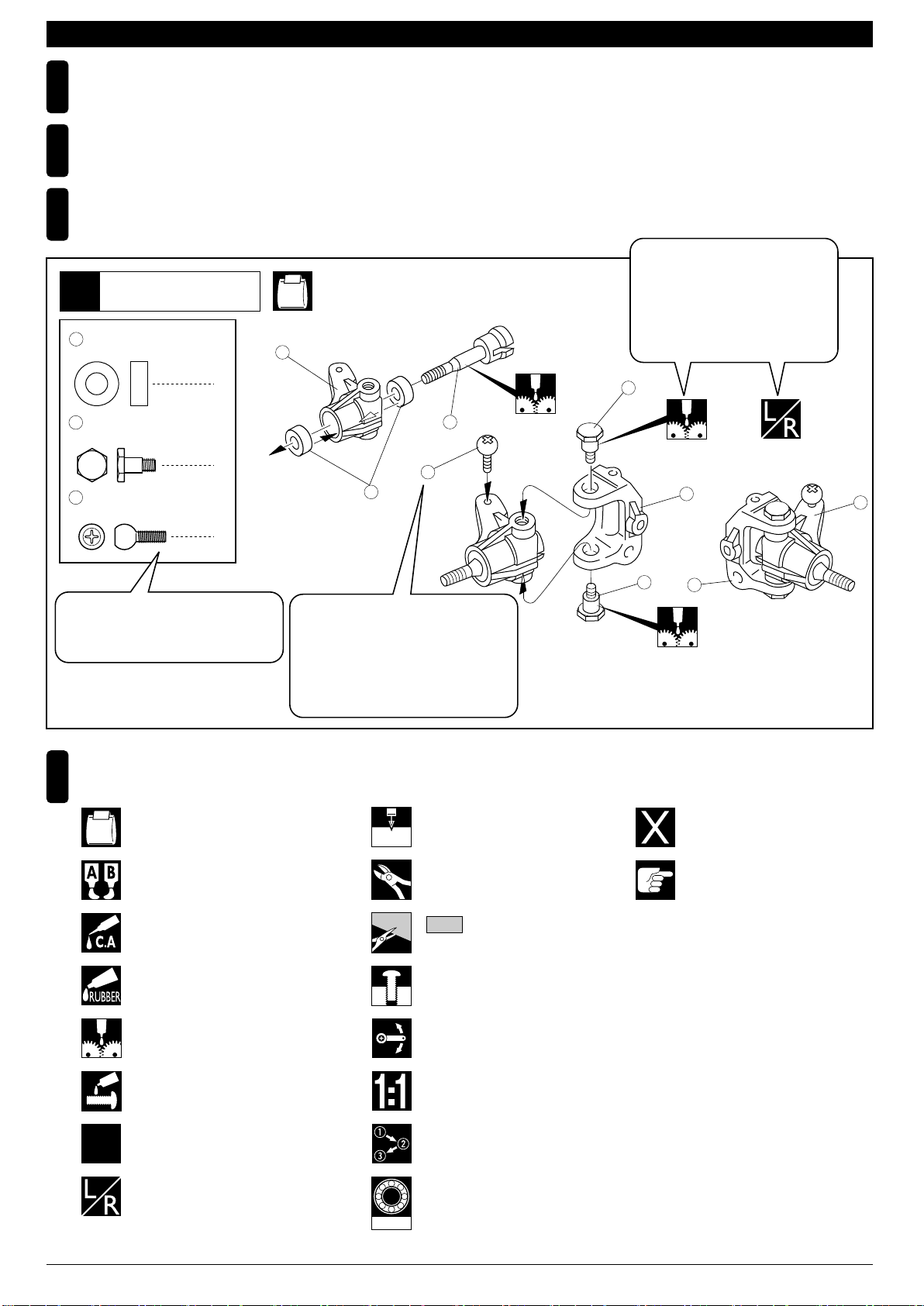
組立て前の注意(1) BEFORE YOU BEGIN (1)
組立てる前に説明書を良く読んで、おおよその構造を理解してから組立てに入ってください。
1
Read through the manual before you begin, so you will have an overall idea of what to do.
キットの内容をお確かめください。万一不良、不足がありましたら、お買い求めの販売店にご相談いただくか、当社「ユーザー相談室」までご連絡ください。
2
Check all parts. If you find any defective or missing parts, contact your local dealer or our Kyosho Distributor.
説明書の見かた
3
How to read the instruction manual:
〔説明例Example〕
説明書内では多くのマークが使用
フロントサスペンション
Front Suspension
1
4
5 x 10mm メタル
Metal Bushing
No.4, No.5, No.6
1
されています。マークに注意して
組立てを進めてください。
This instruction manual uses several symbols. Please note them
during the entire assembly.
4
キングピン
5
King Pin
4
5.8mm ピロボール(黒)
6
Pillow Ball (Black)
2
小物部品の名前、原寸図、使用数。
Key Number, Part Name, True-to-scale
Diagram, Quantity Used
説明書に使われているマーク
4
Symbols used throughout the instruction manual, comprise:
使用する袋詰。
Part bags used.
キット内の部品は、ビス類を除いてキー
No.が付けられています。スペアパーツを
購入する時はキーNo.を参照して下さい。
All parts except screws are identified by
key numbers. For purchasing spare parts,
find the key no. of the part needed in the
spare part list and refer to the left column
to look up the corresponding order no.
4
2mm
3
6
2mmの穴をあける(例)。
Drill holes with the specified
diameter (here: 2mm).
5
7
R
L
5
8
別購入品。
Must be purchased separately!
2
x2
エポキシ接着剤で接着する。
Apply epoxy glue.
瞬間接着剤で接着する。
Apply instant glue (CA glue, super glue).
ゴム系接着剤で接着する。
Apply rubber cement.
グリスを塗る。
Apply grease.
ネジロック剤を塗る。
Apply threadlocker (screw cement).
2セット組立てる(例)。
Assemble as many times as
specified (here: twice).
左右同じように組立てる。
Assemble left and right sides
the same way.
BRG001
余分をカットする。
Cut off excess.
をカットする。
Cut off shaded portion.
仮止め。
Temporarily tighten.
可動するように組立てる。
Ensure smooth non-binding
movement while assembling.
原寸図。
True-to-scale diagram.
番号の順に組立てる。
Assemble in the specified
order.
オプションのベアリングの品番。
例 : No.BRG001
Ball bearings are optional!
(with optional part no.)
注意して組立てる所。
Pay close attention here!
4
Page 5
組立て前の注意(2) BEFORE YOU BEGIN (2)
キットには、形や長さが違うビスや小物部品が多く入っています。説明書には原寸図がありますので確認してから組立ててください。
5
また、ビス類は多めに入っているものもありますので、予備としてお使いください。
This kit contains screws and hardware in different metric sizes and shapes.
Before using them, check the screws on the true-to-scale diagrams on the left side in each assembly step. Some screws are extras.
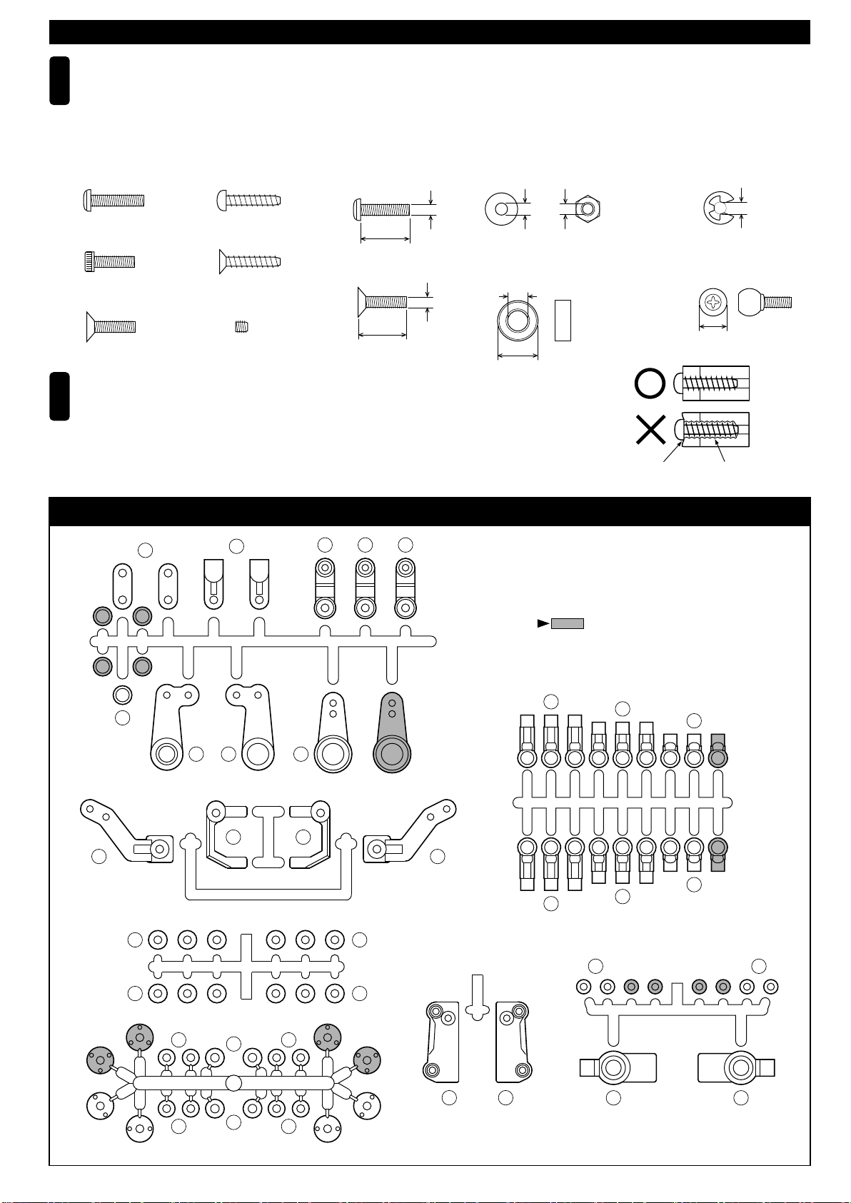
●ビスの種類 SCREWS
ビス Screw
キャップビス
Cap Screw
サラビス
Flat Head (F/H) Screw
TPビスは、部品にネジを切りながらしめつけるビスです。しめこみが固い場合がありますが、
6
部品が確実に固定されるまでしめこんでください。ただし、しめすぎるとネジがきかなくなり
ますので、部品が変形するまでしめないでください。
Self-tapping (TP) screws cut threads into the parts when being tightened. Excessive force may
permanently damage parts when tightening TP screws. It is recommended to stop tightening when
the part is attached or when some resistance is felt after the threaded portion enters the plastic.
TPビス
Self-tapping (TP) Screw
TPサラビス
TP F/H Screw
セットビス
Set Screw
●小物部品のサイズ例 OTHER HARDWARE
3x12mmビス
Screw
12mm
3x12mmサラビス
F/H Screw
3mm
12mm
3mmワッシャー・ナット
Washer・Nut
3mm
5x10mmメタル・ベアリング
Metal Bushing・Bearing
5mm
10mm
ARRANGEMENT OF PLASTIC PARTS ON RUNNERSランナー付プラパーツ配置図 /
26
27
SFH
183181182
3mm
Correct
Wrong
しめすぎ
Overtightened.
E3Eリング
E-ring
3mm
6.8mmピロボール
Pillow Ball
6.8mm
ビスがきかない
The threads are stripped.
29
23
24
R
8 7
6
3 B 3 B
A
3
80
81
80
25
部分の部品は、使用しません。
Shaded Parts are not used.
22
21
20
L
5
20
22
21
3030
10
10
3131
L 3
3
A
R 3
C
2
80 80
2 B
81
C
2
2 B
13 12
9 9
5
Page 6
シャシー
Chassis
1
No.1, No.2, No.4
3mm
15
No.30073
194
No.30073B
3mm
127
No.30073
186
No.30073B
105
3 x 8mm
F/H Cap Screw
3mm
Nylon Nut
サラキャップビス
ナイロンナット
シャシー
Chassis
2
3 x 8mm
F/H Cap Screw
3 x 12mm
Button Cap Screw
59
109
サラキャップビス
ボタンキャップビス
4.8mm
ボールスタッド(S)
Ball Stud (S)
2.6 x 16mm
Shaft
シャフト
8
4
1
2
2
1
3x8mm(F/H)
108
No.30073
188
No.30073B
No.2, No.3
107
No.30073
187
No.30073B
3x8mm(F/H)
109
向きに注意。
Note the direction.
3x8mm(F/H)
3x12mm
110
189
59
3x8mm(F/H)
No.30073
No.30073B
59
リヤダンパーステー
Rear Shock Stay
3
3 x 20mm
Button Cap Screw
3 x 15mm
Button Cap Screw
3 x 10mm
F/H Cap Screw
3mm
Nut
ボタンキャップビス
ボタンキャップビス
サラキャップビス
ナット
3x8mm(F/H)
128
No.30073
No.2
2
2
3x15mm
2
2
111
3x10mm(F/H)
3x20mm
190
No.30073B
向きに注意。
Note the direction.
3mm
使用する袋詰。
Part bags used.
6
左右同じように組立てる。
Assemble left and right sides the same way.
Page 7
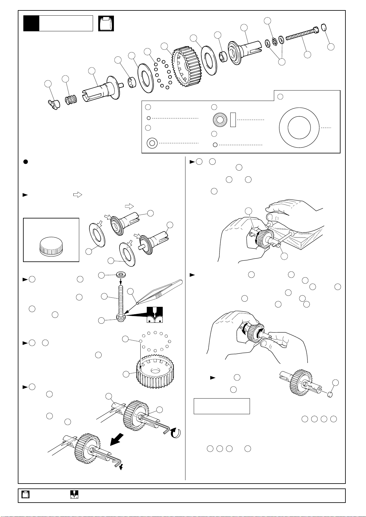
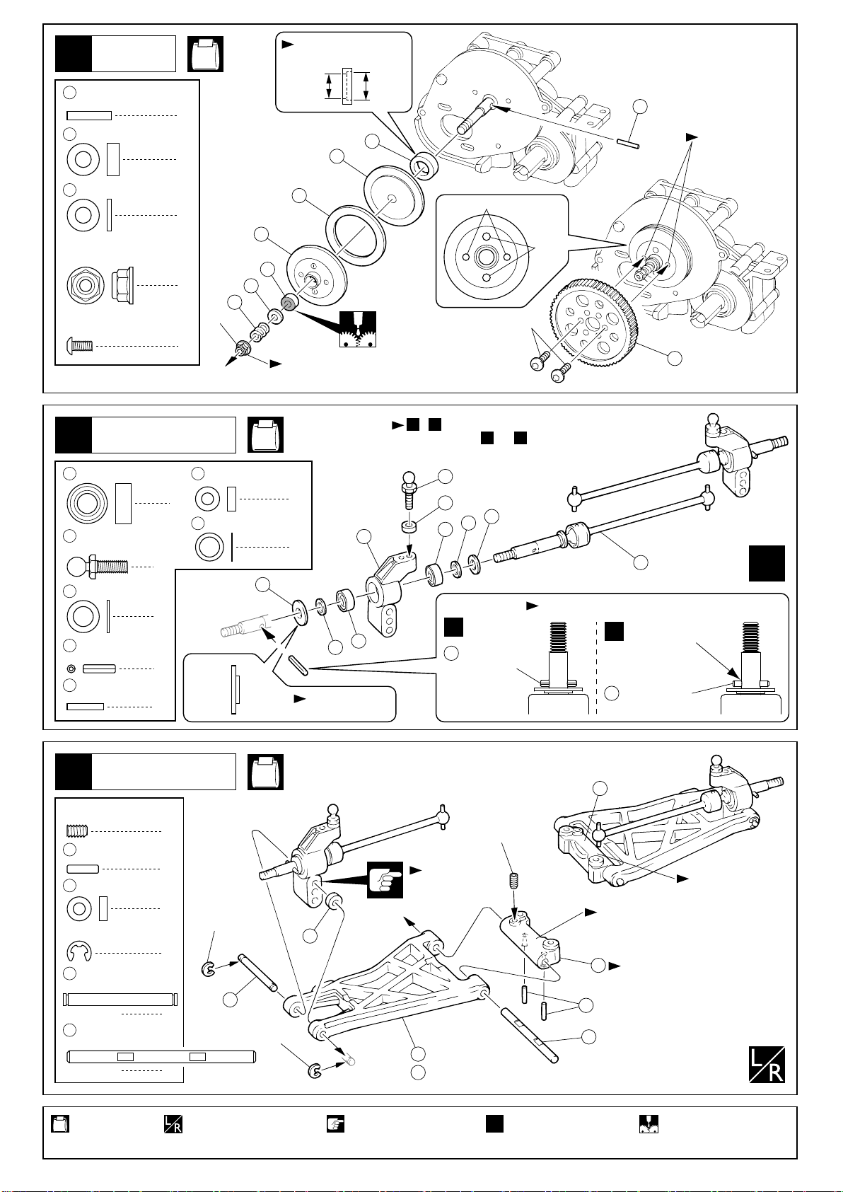
デフギヤ
Gear Differential
4
分解図
EXPLODED VIEW
45
40
34
No.1
50
37
< >ボールデフユニット
< >Ball Diff unit
37
36
38
55
1/16
スラストボール
Thrust Ball
54
スラストワッシャー
Thrust Washer
50
50
4 x 8mm
Ball Bearing
8
38
3/32
Ball Bearing
2
35
ベアリング
ベアリング
12
55
54
37
2
41
39
スラストプレート
Thrust Plate
2
組立ては上の分解図を参考にしてください。
下記の点に注意してください。
Assemble with the aid of the above exploded view and pay
attention to the following.
油分をとり(脱脂)、 の所にボールデフグリスを少し塗る。
Remove oil deposits from before applying a small amount of ball
differential grease to the spots marked with .
35
ボールデフグリス
Ball Differential Grease
37
37
はグリスを塗った に
55
8個並べる。
After applying Grease, place
eight differential balls between the two thrust washers
, grouping them around
54
the screw .
39
54
55
54
55
39
54
を に組込み、ボールデフ
38
36
グリスを塗る。
Place the differential balls into
and apply ball differential grease.
38
38
34
と をマイナスドライバーで固定し、本体を回してみる。
34 35
回らなくなるまで をしめ込む。回ってしまう状態のまま走行
させると破損するので注意。
Secure parts and in place with two flat head screwdrivers
and rotate the differential case until it becomes tight. Then, tighten
screw . When running the car, the differential must be tight,
39
otherwise it may be damaged.
34
39
35
34
35
次に本体を手で固定し、 を回したとき、 が反対方向に回転す
れば良い。回らないときはしめ込み過ぎなので、 をゆるめる。
Now, hold the differential case firmly and rotate part . If part
rotates into the opposite direction to part , no further adjustment
is necessary. If part does not rotate, screw is too tight.
In this case, gradually loosen screw until part rotates.
36
35
39
36
39
35 36
35
39
36
をマイナスドライバーで
34
固定し、 をいっぱいにしめ
込み、それから1/8回転ゆるめる。
(後で調整する)
Tighten with a screwdriver
and fully tighten then rewind
1/8 turn.
(Adjust it later)
39
34
39
使用する袋詰。 グリスを塗る。
Part bags used. Apply grease.
34
36
39
調整後、 を取付ける。
Once the adjustment is done,
install (see"exploded view").
41
41
41
メンテナンス
MAINTENANCE
作動させたときになめらかに動かなくなったら、 , , ,
が汚れています。分解して掃除してください。それでも直らない
ときは、これらのパーツが消耗しているので交換してください。
また、これらのパーツは定期的に交換するとよいでしょう。
As soon as the ball differential's smooth action becomes rough,
parts , , and may have become "gritty". If this
37 38 54 55
happens, disassemble the unit and clean these parts, apply more
grease and reassemble. If the action is still not smooth, the parts
are worn and, therefore, must be replaced. We recommend that
these parts be replaced from time to time to ensure smooth running.
37 38 54 55
7
Page 8
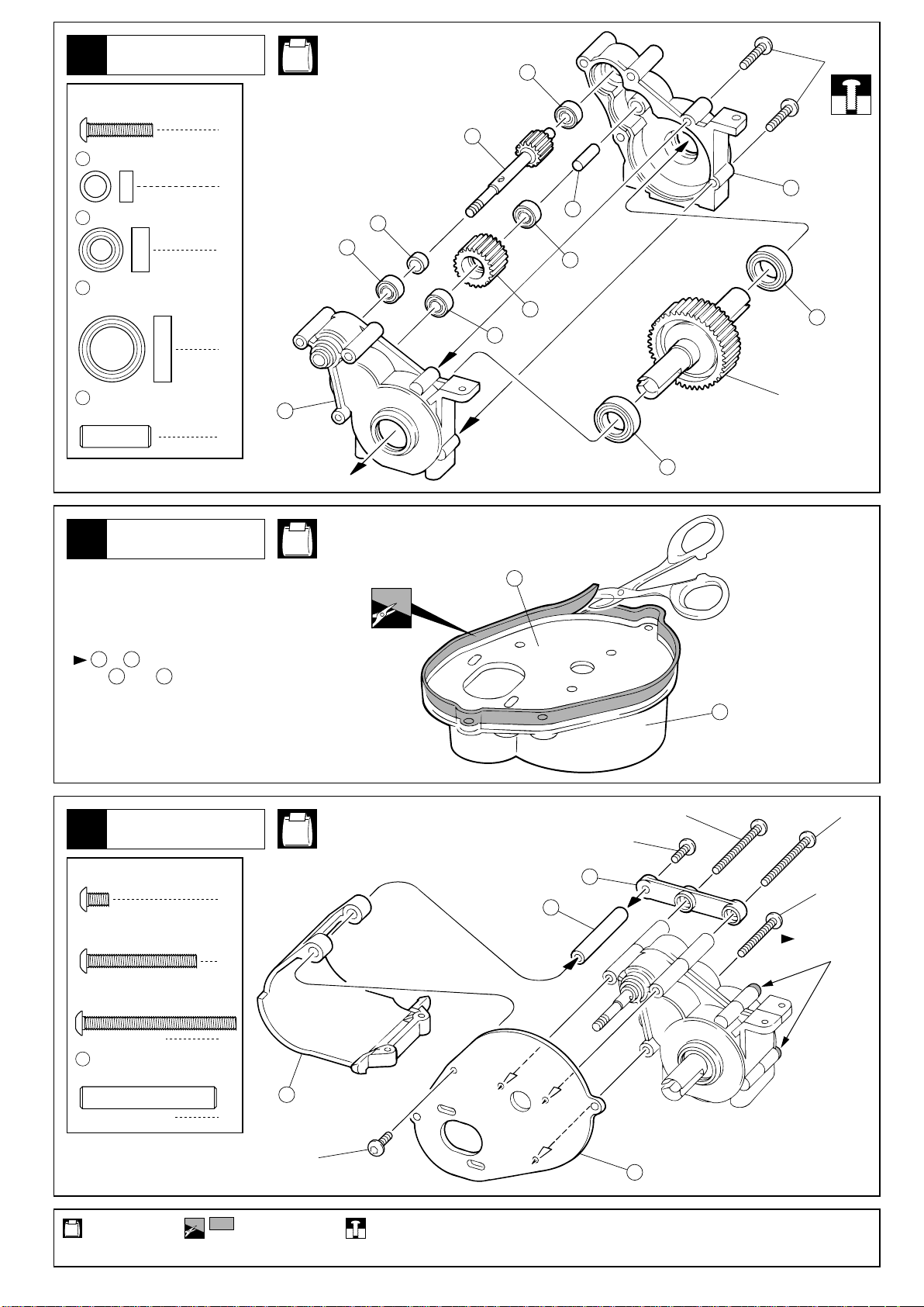
リヤギヤボックス
Rear Gearbox
5
3 x 15mm
Button Cap Screw
70
5 x 7 x 3mm
Collar
51
5 x 10mm
Ball Bearing
52
10 x 15mm
Ball Bearing
ボタンキャップビス
カラー
ベアリング
ベアリング
No.1
51
2
1
106
3x15mm
113
49
70
4
51
115
51
52
51
2
49
5 x 16mm
Aluminium Shaft
6
を にはめ込み余分な所をカットします。
119 120
Fit into , and trim off the area sticked out.
7
アルミシャフト
112
1
ギヤボックス
Gearbox
119 120
ギヤボックス
Gearbox
No.1
No.1, No.2
119
3x5mm
52
3x35mm
デフギヤ
Differential
120
3x35mm
3 x 5mm
Button Cap Screw
3 x 25mm
Button Cap Screw
3 x 35mm
Button Cap Screw
118
使用する袋詰。
Part bags used.
ボタンキャップビス
ボタンキャップビス
ボタンキャップビス
5 x 31mm
アルミシャフト
Aluminium Shaft
8
2
1
2
32
1
3x5mm
をカットする。
Cut off shaded portion.
114
3x25mm
118
本締めする。
Tighten securely.
119
仮止め。
Temporarily tighten.
Page 9
メインギヤ
Main Gear
8
2 x 11mm
71
Shaft
160
4 x 8mm
Metal Bushing
46
4 x 8mm
Thrust Plate
4mm
Flanged Nylon
2.6 x 5mm
Button Cap Screw
シャフト
メタル
スラストプレート
フランジ付ナイロンナット
ボタンキャップビス
No.1
1
1
1
向きに注意。
Note the direction.
内側外側
InsideOutside
116
42
44
71
2.6mmビス穴に
ねじ込む。
Tighten 2.6mm
screw
2.6mm
43
3mm
160
1
46
161
4mm
2
しめ込んだ状態から1/2回転もどす。
Rewind 1/2 turn from firmly tightened condition.
2.6x5mm
135
リヤサスペンション
Rear Suspension
9
51
5 x 10mm
Ball Bearing
58
4.8mm
ボールスタッド(L)
Ball Stud (L)
73
5 x 8 x 0.5mm
Shim
74
1.5 x 8mm
Roll Pin
17121.6 x 9mm
Pin
ロールピン
ピン
リヤサスペンション
Rear Suspension
10
3 x 5mm
Set Screw
174
10
E2.5
E-ring
69
66
セットビス
2 x 7.8mm
Pin
3 x 6 x 2mm
Plastic Collar
3 x 26mm
Shaft
3 x 47mm
Shaft
プラカラー
Eリング
ベアリング
2
シム
2
2
2
ピン
4
2
4
シャフト
2
シャフト
2
10
3 x 6 x 2mm
Plastic Collar
4
5 x 7 x 0.1mm
172
Shim
E2.5
69
プラカラー
シム
173
内側外側
InsideOutside
E2.5
No.3, No.4
2
4
172
向きに注意。
Note the direction.
No.4
10
, の2通りの組み立てが出来ます。BA
Choose either or .A B
58
10
9
51
A
51
< Left >
左側用
74
取付穴。
Use this hole.
130
No.30073
191
No.30073B
73
172
スプリングピン
Spring Pin
3x5mm
L3
129
均等に入れる。
< Right >
右側用
Insert equally.
ゴム系接着剤等
B
で固定する。
Apply rubber
cement.
171
ニードルピン
Needle Pin
13
R3
L3のマーク
ÒL3Ó marked
12
向きに注意。
Note the direction.
174
66
x2
R3のマーク
ÒR3Ó marked
使用する袋詰。
Part bags used.
左右同じように組立てる。
Assemble left and right
sides the same way.
注意して組立てる所。 2セット組立てる(例)。
Pay close attention here!
x2
Assemble as many
times as specified.
グリスを塗る。
Apply grease.
9
Page 10
リヤサスペンション
Rear Suspension
11
No.3, No.4
131
3 x 40mm
Adjust Rod
アジャストロッド
21
左側
22
(長)
(Long)
131
21
(中)
(Medium)
< Left >
131
22
< Right >
右側
段のある方が逆ネジ。
The side with the step is
2
a reverse screw.
21
(中)
(Medium)
25.5mm
段のある方。
Projection. Note direction.
131
22
(長)
(Long)
3 x 8mm
F/H Cap Screw
21
22
サラキャップビス
4.8mm
ボールエンド(中)
Ball End (Medium)
4.8mm
ボールエンド(長)
Ball End (Long)
162
リヤギヤボックス
Rear Gearbox
12
3 x 8mm
F/H Cap Screw
サラキャップビス
4
2
2
6
左側用
For Left
段のある方。
Projection.
Note direction.
162
162
3x8mm
右側用
For Right
3x8mm(F/H)
段のある方。
Projection.
Note direction.
3 x 8mm
Button Cap Screw
使用する袋詰。
Part bags used.
ボタンキャップビス
ユニバーサルシャフトを入れる。
Put universal shaft.
左右同じように組立てる。
Assemble left and right sides the same way.
2
3x8mm(F/H)
3x8mm(F/H)
原寸図。 注意して組立てる所。
True-to-scale diagram. Pay close attention here!
3x8mm(F/H)
10
Page 11

フロントサスペンション
Front Suspension
13
3 x 10mm
Button Cap Screw
3 x 18mm
Button Cap Screw
ボタンキャップビス
ボタンキャップビス
3x18mm
No.2, No.3, No.4
3x10mm
3
取付穴。
2
Use this hole.
58
3mm
132
向きに注意。
Note the direction.
65
133
No.30073
193
No.30073B
3mm
Nylon Nut
58
4.8mm
Ball Stud (L)
65
3 x 34mm
Shaft
ナイロンナット
ボールスタッド(L)
シャフト
フロントサスペンション
Front Suspension
14
30
3 x 7 x 1mm
Plastic Collar
31
3 x 7 x 2mm
Plastic Collar
3 x 3mm
Set Screw (
E2.5 E-ring
58
4.8mm
Ball Stud (L)
プラカラー
プラカラー
セットビス(緩み止め付き)
Apply cement to set screw
Eリング
ボールスタッド(L)
2
2
3mm
ナット
Nut
2
< Right >
右側
6
6
6
)
2
2
2
Rのマーク
ÒRÓ marked
No.3, No.4
56
3mm
Nylon Nut
2
30
31
30
E2.5
ナイロンナット
133
No.30073
193
No.30073B
67
30
31
65
8
向きに注意。
Note the direction.
8
六角レンチ(1.5mm)
Hex Wrench (1.5mm)
前
Front
58
31
16
3x3mm
64
5
7
< Left >
左側
(緩み止め付き)
(Apply cement to
set screw)
Lのマーク
ÒLÓ marked
フロントサスペンション
Front Suspension
15
段のある方が逆ネジ。
The side with the step is
a reverse screw.
21
サスシャフト(銀)
68
Suspension Shaft (Silver)
21
4.8mm
ボールエンド(中)
Ball End (Medium)
134
3 x 50mm
Adjust Rod
アジャストロッド
134
E2.5
E-ring
2
4
162
2
Eリング
右側用
For Right
No.3, No.4
21
4
< Left >
左側
< Right >
右側
段のある方。
Projection.
Note direction.
E2.5
162
(Medium)
21
(中)
(Medium)
21
(中)
38mm
段のある方。
Projection.
Note direction.
E2.5
68
134
134
21
(中)
(Medium)
21
(中)
(Medium)
段のある方。
Projection.
Note direction.
左側用
For Left
使用する袋詰。
Part bags used.
左右同じように組立てる。
Assemble left and right sides the same way.
原寸図。 注意して組立てる所。
True-to-scale diagram. Pay close attention here!
11
Page 12

フロントサスペンション
Front Suspension
16
No.2
3 x 8mm
F/H Cap Screw
3 x 10mm
F/H Cap Screw
17
サラキャップビス
サラキャップビス
ステアリング
Steering
3x10mm
2
2
3x10mm(F/H)
No.3
2mm
3x10mm(F/H)
3x8mm(F/H)
60
59
33
3x8mm(F/H)
約24mm
approx. 24mm
( Short)
20
3 x 10mm
Set Screw
20
4.8mm
Ball End (Short)
59
4.8mm
Ball Stud (S)
18
159
5 x8 x 2.5mm
Ball Bearing
63
5 x 31mm
セットビス
ボールエンド(短)
ボールスタッド(S)
ステアリング
Steering
ベアリング
アルミシャフト
Aluminium Shaft
短
61
25
1
59
23
162
2
59
5
No.3
29
62
159
59
24
向きに注意。
Note the direction.
159
4
159
159
63
2
63
使用する袋詰。
Part bags used.
12
原寸図。
True-to-scale diagram.
Page 13

ボディマウント
Body Mounts
19
No.4
3x10mm(F/H)
14
No.30073
195
No.30073B
3x12mm(F/H)
3x8mm(F/H)
3x10mm(F/H)
3x8mm(F/H)
3x12mm(F/H)
3 x 8mm
F/H Cap Screw
3 x 10mm
F/H Cap Screw
3 x 12mm
F/H Cap Screw
サラキャップビス
サラキャップビス
サラキャップビス
フロントサスペンション
Front Suspension
20
段のある方が逆ネジ。
The side with the step
is a reverse screw.
22
22
4.8mm
ボールエンド(長)
Ball End (Long)
131
3 x 40mm
Adjust Rod
アジャストロッド
2
2
2
4
131
No.3, No.4
22
22
段のある方。
Projection.
Note direction.
162
(長)
(Long)
段のある方。
Projection.
Note direction.
30.5mm
131
22
(長)
(Long)
段のある方。
Projection.
Note direction.
x2
2
プロポ
Radio
21
3 x 8mm
Button Cap Screw
59
3mm
Washer
2.6 x 8mm
TP Screw
使用する袋詰。
Part bags used.
ボタンキャップビス
4.8mm
ボールスタッド(S)
Ball Stud (S)
ワッシャー
サーボに付属するビスと同じタイプを使用する。
Use screws which are same type included in your servo.
フタバ用
for FUTABA
TPビス
1
No.3
使用するサーボに合わせる。
4
1
4
2.6 x 8mm
Screw
左右同じように組立てる。
Assemble left and right
sides the same way.
Select for your servo.
FUTABA
SANWA
KO
JR
HITEC
ビス
1
サンワ用
3 x 8mm
Button Cap Screw
x2
ステアリングサーボ
Steering Servo
181
182
HF S
for SANWA
ボタンキャップビス
2セット組立てる(例)。
Assemble as many
times as specified.
183
1
59
3mm
3x8mm
90¡
F
注意して組立てる所。 別購入品。
Pay close attention here! Must be purchased
下のサイズの場合は、 を使用します。
In case of the following sizes, use 26 .
separately!
27
26
26
10mm以下の場合
Shorter than 10mm.
28mm以上の場合
Longer than 28mm.
原寸図。
True-to-scale
diagram.
13
Page 14

22
20
(短)
(Short)
プロポ
Radio
3x10mm
1mm
20
(短)
(Short)
No.3
ステアリングサーボ
Steering Servo
162
162
3 x 10mm
Set Screw
20
4.8mm
Ball End (Short)
セットビス
ボールエンド(短)
モーター
Motor
23
3 x 5mm
3 x 3mm
Set Screw
3mm
Washer
ボタンキャップビス
Button Cap Screw
セットビス
ワッシャー
紙1枚分のすき間を
つくって固定する。
Tighten the screws with
one sheet of paper
inserted between
both gears.
1
3 x 8mm
F/H Cap Screw
2
2
1
モーター
Motor
2
サラキャップビス
No.1
2
3x8mm(F/H)
六角レンチ(1.5mm)
Hex Wrench (1.5mm)
3x5mm
3x3mm
136
平らな面にセット
ビスを固定する。
Firmly tighten the
set screws onto
the flat spots.
136
3x5mm
標準のピニオンギヤは11T程度のモーターに対応します。
Kit pinion gear for use with 11 turn motor.
ギヤボックス
Gearbox
24
3 x 5mm
Button Cap Screw
使用する袋詰。 別購入品。
Part bags used.
ボタンキャップビス
Must be purchased separately!
14
No.1
2
3x5mm
120
3x5mm
原寸図。
True-to-scale diagram.
121
Page 15

ダンパー
Shock
25
80
3 x 6 x 1mm
Plastic Collar
81
3 x 7 x 1mm
Plastic Collar
86
5.8mm
Ball End (S)
E2.5
Oリング
94
95
Cリング
プラカラー
プラカラー
ボールエンド(S)
Eリング
E-ring
O-ring
C-ring
8
4
8
4
4
8
92
Oリング(中)
溝にはめる。
Fit into groove.
95
オイルを少し
付ける。
Put a little oil.
O-ring (M)
4
No.5
95
81
94
80
94
80
92
76
< for Rear >
リヤ用
約28mm
approx. 28mm
< for Front >
フロント用
約19.5mm
approx. 19.5mm
フロント 2-C
79
Front 2-C
リヤ 2-B
79
Rear 2-B
E2.5
フロント用(短)
137
for Front (Short)
リヤ用(長)
89
for Rear (Long)
E2.5
x2
x2
86
オイルを
少し付ける。
Put a little oil.
ダンパー
Shock
26
A
B
フロント用(短)
139
for Front (Short)
リヤ用(長)
78
for Rear (Long)
プレッシャータイプ
Pressure Type
フロント用(短)
for Front (Short)
リヤ用(長)
for Rear (Long)
フロント用(短)
139
for Front (Short)
リヤ用(長)
78
for Rear (Long)
エアレーションタイプ
Non-Pressure Type
No.5
1
ピストンを下げ、
オイルを図の
位置まで入れる。
Pull down the
piston and slowly
fill in oil.
1
オイルを入れる。
Put the oil.
93
, の2通りのダンパーの組立てが出来ます。
BA
75
85
96
0~1mm
3
もう一度図の位置
までオイルを足す。
Add oil one more
time up to the brim.
2
上下させ、気泡をとる。
Move the piston up and
down to get rid of air
bubbles.
2
伸ばしておく。
Keep expanded.
4
シャフトをゆっくり押し込む。
Insert the shaft slowly.
3
キャップを軽く止
まる所まで締め、
1/2回転ゆるめる。
Tighten the cap until
it slightly stops,
then loosen it for a
1/2nd lap.
You can assemble the shock in 2 ways.
4
, , の順に組立てる。
96 7585
Complete the shock assembly
in the order , and .
96 85 75
余分なオイルが出る。
Surplus oil comes out.
5
スムーズに動くか確認する。
Confirm that each piston
moves up and down
smoothly.
5
キャップを最後まで
締め込み、シャフト
を伸ばす。
Tighten the cap firmly,
and pull the shaft.
93
Oリング(大)
O-ring (Large)
使用する袋詰。
Part bags used.
85
75
4
2セット組立てる(例)。
x2
Assemble as many times as specified.
余分なオイル
が出る。
Surplus oil comes out.
別購入品。
Must be purchased separately!
15
Page 16

27
ダンパー
Shock
No.5
97
5.8mm
Ball
ボール
150
フロント用(短)
for Front (Short)
151
リヤ用(長)
for Rear (Long)
ダンパー
Shock
28
< Front >
フロント
82
98
8
スプリング調整用。
For adjusting the spring tension.
は5種類あるので………
98
1
車高の前後が、水平になるように
2
走行しながら………種類、個数を調節する。
exists in 5 widths. For making the F / R ground
98
clearance horizontal, choose the necessary width(s)
and amount of . When adjusting, run your car.
98
No.5
83
向きに注意。
Note the direction.
フロント用(短)
for Front (Short)
リヤ用(長)
for Rear (Long)
87
スプリングを縮めて を入れる。
Compress the spring and install .
97
フロント用(短)
For Front (Short)
84
84
84
97
3 x 10mm
3 x 12mm
87
プラナット
Plastic Nut
ボタンキャップビス
Button Cap Screw
2
ボタンキャップビス
Button Cap Screw
2
4
3x12mm
< Rear >
リヤ
取付穴。
Use this hole.
3x10mm
83
向きに注意。
Note the
direction.
リヤ用(長)
For Rear (Long)
87
リヤ用(長)
For Rear (Long)
使用する袋詰。
Part bags used.
16
左右同じように組立てる。
Assemble left and right sides the same way.
注意して組立てる所。
Pay close attention here!
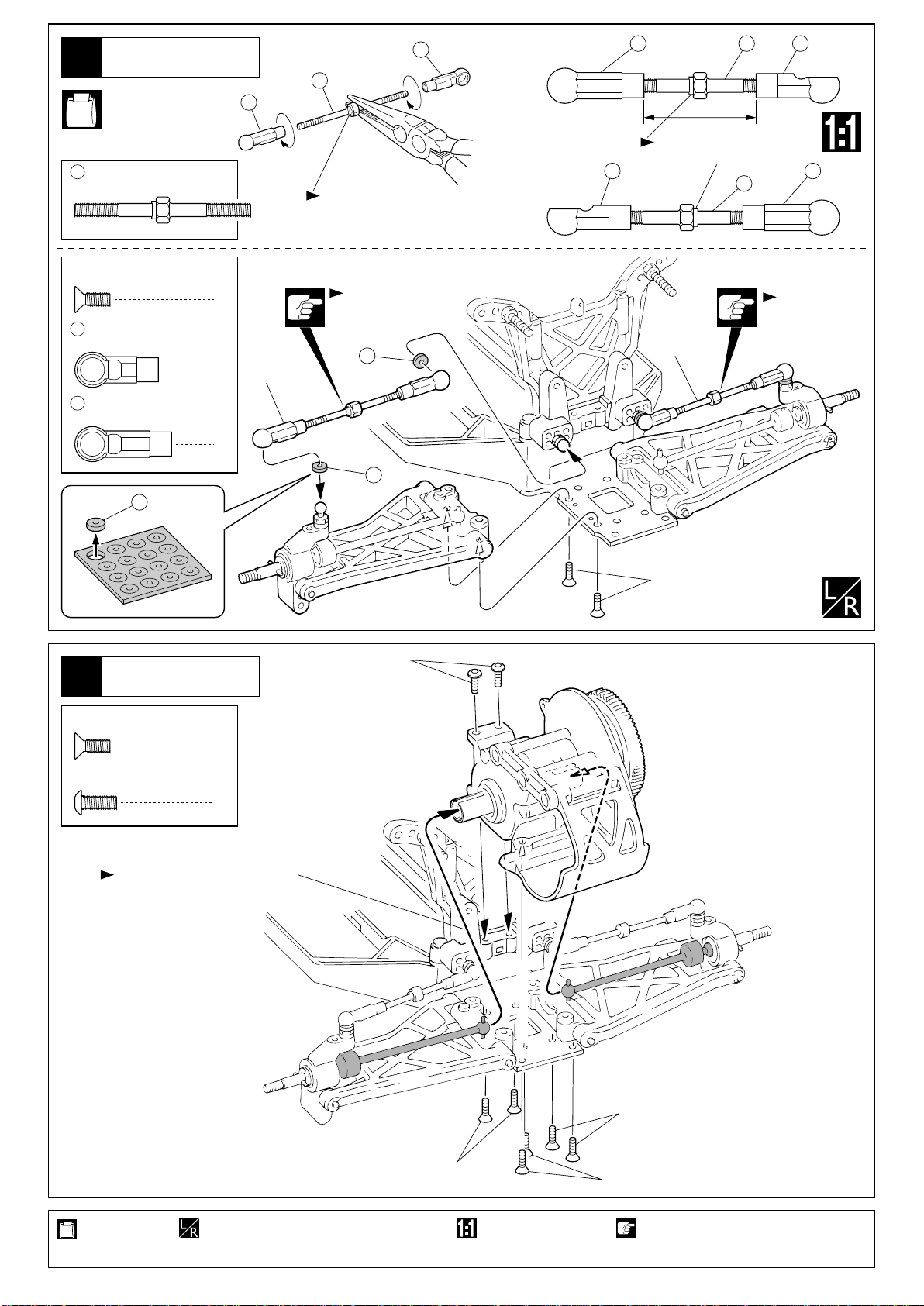
Page 17

プロポ
Radio
29
No.2
125
両面テープ
Double-sided Tape
プロポの説明書を参考に、
コネクターを接続する。
Connect as per radio
instruction manual.
コードをストラップで束ねる。
Bind the wires with strap.
受信機
Receiver
163
126
アンテナ
Antenna
アンテナ
Antenna
アンプ
Speed Controller
30
バッテリー
31
バッテリー
Battery
No.2
Battery
バッテリー
Battery
シャシーのスリットに通す。
Pass the code through the slit of the chassis.
< >セパレートバッテリーの場合
< >For Separated Battery
117
スポンジ スポンジ
Sponge
< >セパレートバッテリーの場合
< >For Separated Battery
125
両面テープ
Double-sided Tape
< >ストレートバッテリーの場合
< >For straight packed Battery
バッテリー
Battery
< >ストレートバッテリーの場合
< >For straight packed Battery
117
Sponge
No.2
117
スポンジ
Sponge
48
スナップピン
Snap Pin
1
使用する袋詰。 別購入品。
Part bags used.
Must be purchased separately!
48
48
バッテリー、モーターの説明書を参考にコードを接続する。
Connect the cords properly with reference to manuals of battery and motor.
17
Page 18

タイヤ
Wheels
32
< Front > < Rear >
フロント
リヤ
143
140
142
(フロント用)
(for front)
141
(フロント用)
(for front)
144
(リヤ用)
(for rear)
145
(リヤ用)
(for rear)
x2x2
33
4mm
タイヤ
Wheels
< Rear >
リヤ
裏から見た図。
Illustration from
reverse side.
ピッタリはめてからタイヤとホイールの
つなぎ目に瞬間接着剤を流し接着する。
After fitting wheels to tyres, apply instant
glue as shown.
No.4
ピンをホイール
の溝に合わせる。
Drive pin must
fit into wheel
groove.
裏から見た図。
Illustration from
reverse side.
ピッタリはめてからタイヤとホイールの
つなぎ目に瞬間接着剤を流し接着する。
After fitting wheels to tyres, apply instant
glue as shown.
リヤ用
For Rear
4mm
フランジ付ナイロンナット
Flanged Nylon Nut
53
3/16 x 3/8
Ball Bearing
使用する袋詰。
Part bags used.
インチベアリング
18
< Front >
フロント
4mm
4
4
53
瞬間接着剤で接着する。
Apply instant glue (CA glue, super glue).
53
フロント用
For Front
左右同じように組立てる。
Assemble left and right sides
the same way.
2セット組立てる(例)。
x2
Assemble as many times as specified.
Page 19

34
ボディ
Body Shell
147
146
6mm
5mm
6mm
塗装
Painting
35
塗装前に、洗剤で油やよごれを洗う。 ウインドウ部分に、
1
Before painting, use a neutral detergent
to remove any oil residues and dirt.
塗分けはパッケージ
3
写真も参考にして
ください。
Refer to the pictures
on the box for the
color scheme.
京商スプレーカラーでボディ内側を塗装する。
Paint the body shell from the
inside using KyoshoÕs
spray colors.
2
内側からマスキング
シートを貼る。
Mask the windows
from the inside.
塗装後、ボディ表面の保護ビニール
4
シートをはがしておく。
After painting, remove the
protective film from the
body shell.
マスキング
Mask
マスキング
Mask
をカットする。 6mmの穴をあける(例)。
Cut off shaded portion. Drill holes with the specified diameter.
6mm
19
Page 20

ボディ
Body Shell
36
3 x 3mm
Set Screw
セットビス
1
No.2
2
148
1
2
2
149
を図のように通して3x3mm
149
セットビスで固定する。
Let item number go through
the hole of the wing as shown.
3
149
3
3x3mm
デカール
Decals
37
デカールは、好きな位置に貼って下さい。
Decals with can be placed wherever you like.
使用する袋詰。
Part bags used.
20
番号の順に組立てる。
Assemble in the specified order.
Page 21

38
ボディ
Body Shell
48
48
48
フックピン
Hook Pin
2
走行上の注意
Safety Precautions
走行時は、必ずボディを装着してください。
必要以上に前/後進の操作を繰り返すことは、おやめください。
下記の場所での走行は、故障の原因になりますのでおやめください。
・シャシーにからむような草の生えているところ。
・泥地、砂地、砂利の多いところ。
定期的に、各部のビス類が緩んでないか確認してください。
オプションパーツ
OPTIONAL PARTS How to install long suspension arm (UMW409)
ロングリヤサスペンションアーム(UMW409)の取り付け
W5063
Always run your car with the body shell mounted!
Avoid changing the running direction too often and too abruptly.
Do not run your car on ground:
・ that is overgrown with grass.
・ that is muddy, sandy or rocky.
Check all screws, nuts etc. on a regular basis for looseness.
1
< Left >
左側用
取付穴。
Use this hole.
< Right >
右側用
13
R3
3x5mm
L3
R3のマーク
ÒR3Ó marked
L3のマーク
ÒL3Ó marked
E2.5
注意して組立てる所。 別購入品。 左右同じように組立てる。
Pay close attention here! Must be purchased separately! Assemble left and right sides the same way.
69
E2.5
UMW409
66
12
向きに注意。
Note the
direction.
21
Page 22

2
22
131
段のある方が逆ネジ。
The side with the step is
a reverse screw.
段のある方。
Projection.
Note direction.
21
3x20mm
162
< Left >
左側
< Right >
右側
取付穴。
Use this hole.
3mm
22
(長)
(Long)
(中) (長)
(Medium) (Long)
OTW13に交換。
Use OTW13.
37.5mm
段のある方。
Projection. Note direction.
OTW13に交換。
Use OTW13.
段のある方。
Projection.
Note direction.
21
(中)
(Medium)
2221
3
左側用
For Left
162
83
右側用
For Right
3x8mm(F/H)
向きに注意。
Note the
direction.
87
ダンパーの全長はリバウンドに合わせて調整する。
Shock length can be adjusted for different amount
of shock stroke.
キット標準のリヤホイールは使用できません。
Rear wheels included in kit can not be used.
注意して組立てる所。 左右同じように組立てる。 原寸図。別購入品。
Pay close attention here! Assemble left and right sides the same way. True-to-scale diagram.Must be purchased separately!
22
OT19
3x10mm
UMW409に付属。
This is included in UMW409.
穴の大きい方が内側。
The side with big hole
shoud be inside.
内側 外側
Inside Outside
W5028W
4mm
Page 23

OPERATING YOUR MODEL SAFELY取扱いの注意
次のような時、場所では走らせない。思わぬ事故の原因になります。
WARNING: Do NOT operate the model in the following places and situations:
警告
(Non-observance may lead to accidents!)
●周囲に人がいなくて、広い安全な場所で!
1.自動車道路では走らせない。
2.近くに小さな子供がいたり、人の多い場所では走らせない。
3.民家の近くや公園などでは走らせない。
4.室内やせまいところでは走らせない。
※人にケガをさせる原因になります。また、物をこわしたり、
他人の迷惑になります。
Operate the model in spacious areas with no people
around! Do NOT operate it:
1. on roads!
2. in places where children and many people gather!
3. in residential districts and parks!
4. indoors and in limited space!
*
Non-observance may account
for personal injury and
property damage!
●プロポ関係の電池残量は常にチェックする。
電池が減ってくると電波の送・受信が弱くコントロール
ができなくなり、暴走や衝突の原因なります。
Always check the dry batteries in the radio!
When the dry batteries get weaker, transmission and reception of
the radio decrease. You may lose control of your model when
operating it under such condition. This may lead to accidents!
●近くで無線操縦模型を楽しんでいる人がいる。
同じバンドでの同時走行はできません。電波が混信して
コントロールができなくなり、暴走や衝突の原因なります。
Keep in mind that people around you may also
operate a radio control model!
NEVER share the same frequency
with somebody else at the same
time! Signals will be mixed and
you will lose control of your model.
This may lead to accidents!
01
05
●車の動きがおかしい??とき。
すぐに走行を中止しておかしい原因を調べる、原因不明のまま
走行させると、思わぬ故障や事故の原因になります。
When the model is behaving strangely . . .!
Immediately stop the model and check the reason. As long as the
problem is not cleared, do NOT operate it! This may lead to further
trouble and unforeseen accidents!
事故やケガ等の危険防止のため、次のことを必ずお守りください。
WARNING: in order to avoid accidents and personal injury,
警告
be sure to observe the following:
●回転している部分に、指や物などを入れない。
高速回転しているのでケガの原因になります。
Do NOT put fingers or any objects inside
rotating and moving parts!
Rotating / moving at high
speed, you may be
seriously injured!
●走行直後は、モーター、ニカドバッテリー周辺は高温
になっているので、すぐにはさわらない。
ヤケドの原因になります。
After operation, the electric motor and
Ni-Cd battery are hot!
You may burn yourself
seriously touching them!
●ニカドバッテリーを充電する時は、ニカドバッテリー
および充電器の説明書をよく読んで正しく行なう。
充電中は、ニカドバッテリー、充電器が発熱する。
燃えやすい物の上での充電は、火災等の原因になります。
Before charging, please carefully read the explanations
of the Ni-Cd battery and charger unit! While charging,
the Ni-Cd battery and charger unit get hot!
NEVER charge on top of or near easily inflammable material as
this will result in fires!
●ニカドバッテリーをショートさせない。
1.分解、改造は絶対にしない。
2.コードが、回転部分に接触しないようにする。
NEVER short out Ni-Cd batteries!
1. Do NOT disassemble or modify Ni-Cd batteries!
2. Ensure the cords do NOT trail into rotating and moving parts!
●ニカドバッテリーには、有害重金属が使用されている。
火中に投げ入れると、破裂等の原因になります。
Ni-Cd batteries use heavy metals that are noxious to
health!
NEVER throw them into fires as they will explode!
●不要になったニカドバッテリーは、捨てずに販売店に
返却する。
ALWAYS return disused Ni-Cd batteries to the shop!
Do NOT dispose of them into the usual waste stream!
23
Page 24

PRE-RUN CHECKLIST走行前のチェック
ゆるんでいるビスはありませんか。
プロポの電池はありますか。
走行用の電池はありますか。
ギヤのバックラッシュは最適ですか。
ステアリングはプロポの動きとあってますか。
スロットル(アンプ)はプロポの動きとあってますか。
走行場所は安全な所ですか。
近くで同じバンドで無線操縦模型をしている人はいませんか。
走行用のバッテリーは確実に固定されていますか。
タイヤのとりつけは確実ですか。
回転部分にはグリスが塗ってありますか。
可動部分に当たる物はありませんか。
ダンパーは確実に動きますか。
Are all screws securely tight?
Are the radio batteries fully charged?
Are the onboard batteries fully charged?
Is the backlash properly adjusted?
Does the car's steering react according to your transmitter inputs?
Does the speed (electric speed controller) change according to your transmitter inputs?
Is the Ni-Cd battery securely attached?
Is the running area safe?
Is nobody using the same frequency as you do in the same running area at the same time?
A the wheels and tires securely attached?
Are all rotating parts greased?
Do moving parts not contact anywhere?
Do the shocks move and damp?
EVERYDAY MAINTENANCE日常の整備
ねじ、ナットのゆるみ、老化をチェック。
回転部分にはグリスを塗っておく。
コードが路面にこすれたりして破損しているときは修理する。
サーボのコードや受信機のアンテナ線が破損しているときは、使用しているプロポメーカーに
修理を依頼する。
クラッシュによりサスペンションが破損していないかチェック。
ギヤが摩耗または破損していないかチェック。
シャシーの汚れをとる。
Make sure screws and nuts are securely tightened and parts are not worn.
Grease all rotating parts.
Repair wiring if for example cords drag on the ground or cords are damaged.
Should the servo cords and the antenna be damaged, get them repaired by
their manufacturers.
Make sure the suspension train ist broken due to crashes.
Make sure that gears are not worn or damaged.
Remove dirt from the chassis.
24
Page 25

PROPER OPERATING PROCEDURES走行手順 /
走行用のバッテリーを充電。
1
Fully charge the Ni-Cd battery.
走行用バッテリーのコネクターをつなぐ。
4
Connect the Ni-Cd battery.
受信機のスイッチを入れる。
7
Switch on the receiver.
送信機の電池をチェック。
2
Check the transmitter batteries.
CH-2 CH-1
BATT.
送信機のアンテナをのばす。
5
Extend the transmitter antenna.
CH-2
BATT
.
CH-1
ステアリングがプロポのスティックの
8
動きとあっているか確認。
Make sure the model steers according
to your transmitter inputs.
スロットルのステックがニュートラルで
3
あることを確認。
Make sure the throttle control is in neutral.
CH-2 CH-1
BATT.
送信機のスイッチを入れる。
6
Switch on the transmitter.
ON
CH-2 CH-1
BATT.
OFF
スロットル(アンプ)がプロポのスティック
9
の動きとあっているか確認。
Make sure the speed (electric speed controller)
changes according to your transmitter inputs.
ON
ON
走行場所が安全であることを確認。
10
Make sure the running area is safe.
手もとに車を回収する。
1 2
After finishing running, collect your car.
Do not leave on the racing car.
STOP
走行用バッテリーのコネクター
4 5
をはずす。
Disconnect the Ni-Cd battery.
CH-2 CH-1
BATT.
AFTER FINISHING RUNNING 走行が終わったら /
受信機のスイッチを切る。
Switch off the receiver.
OFF
車の汚れをきれいにとる。
Remove dirt from the chassis.
CH-2 CH-1
BATT.
送信機のスイッチを切る。
3
Switch off the transmitter.
CH-2 CH-1
OFF
走行させない時は、必ず電
源スイッチを『OFF』にし、
安全のため必ずニカドバッ
テリーのコネクターを抜き、
確認する
CHECK
本体より外しておく。
※発熱、発火の原因になります。
OFF
BATT.
ON
When NOT using the model, always
switch off the receiver and transmitter!
Furthermore, disconnect the Ni-Cd
battery and remove it from the model!
・This may lead to overheat and fires!
25
Page 26

故障?と思う前に
症 状
サーボが動かない。
モーターがまわらない。
モーターはまわるが走らない。
スピードがおそい。
タイヤを手でまわすと重い
またはまわらない。
スロットルスティックを
はなしても車がとまらない。
原 因
送信機の電池がない。
配線をまちがえている。
走行用バッテリーの容量不足。
配線をまちがえている。 説明書をよく読んで配線する。
コネクターの接触不良。
モーターの故障。 モーターを交換する。
ピニオンギヤがついていない。
または、ビスがゆるんでいる。
走行用バッテリーの容量不足。
アンプの調整不良。 プロポのトリムで調整する。
回転部分にゴミや砂がつまっている。
ギヤのバックラッシュがきつい。 モーターの取付けビスをゆるめてもう一
アンプの調整不良。 プロポのトリムで調整する。
対 策
送、受信機のスイッチを入れる。送、受信機のスイッチがはいっていない。
新しいものに交換する。
プロポの説明書をよく読んでコネクターを
接続する。
走行用バッテリーを充電する。
コネクターのはめこみをきつくする。
ピニオンギヤを止めているビスを
しめる。
走行用バッテリーを充電する。
このとき、Hiに入らないようならアンプの
説明書を読んで、もう一度調整する。
ゴミや砂を取り除きグリスを塗っておく。
度調整する。
このとき、Hiに入らないようならアンプの
説明書を読んで、もう一度調整する。
PROBLEM CAUSE
Steering control servo does not
operate.
Motor does not run.
Motor runs but car does not run.
Not enough speed.
Wheels hardly rotate/do not
rotate at all.
TROUBLESHOOTING
REMEDY
Switch on.Transmitter and/or receiver is not switched on.
Transmitter batteries are weak.
Improper radio installation.
Ni-Cd battery capacity is insufficient.
Improper radio installation. Correct as per instruction manual.
Loose connectors.
Motor trouble. Replace with a new motor.
Pinion gear is not installed.
Or, screw is loose.
Ni-Cd battery capacity is insufficient.
Electronic speed controller is not
properly adjusted.
Dirt entered rotating parts on wheels.
Backlash is too tight. Readjust as per instruction manual.
Replace with new batteries.
Correct as per radio instruction
manual.
Recharge Ni-Cd battery.
Make connectors tighter with minus
screwdriver.
Tighten screw that holds pinion gear.
Recharge Ni-Cd battery.
Adjust throttle trim (transmitter).
Should electronic speed controller not
shift into high, readjust it as per in-
struction manual.
Clean and regrease.
Even when releasing throttle,
car does not run.
26
Electronic speed controller is not
properly adjusted.
Adjust throttle trim (transmitter).
Should electronic speed controller not
shift into high, readjust it as per in-
struction manual.
Page 27

品番
No.
UM103
UM105P
UM106B
UM107
UM108
UM112
UM113
UM114
UM115
UM116
UM117
UM118
UM119
UM121
UM122
UM124
UM125
UM126
UM128
UM129
UM130B
UM131
UM137
UM145
UM302B
UM303B
UM304
UM306
UM307
UM308
UM309
UM310
UM311
BL
UM313
UM322
UM401
UM402
UM403
UM404B
UM405
UM408
BL
パーツ名
Part Names
ナックルアーム
Knuckle Arm
リヤサスホルダー
Rear Suspension Holder
フロントアッパープレート
Front Upper Plate
フロントシャシー
Front Chassis
フロントバルクヘッド
Front Bulk Head
4.8mmボールエンド
4.8mm Ball End Caps
3mmカラー
3mm Collars
リヤバンパー
Rear Bumper
フロントバンパー
Front Bumper
ボールデフシャフト(L)
Outdrive Diff half (L)
ボールデフシャフト(R)
Outdrive Diff half (R)
ボールデフギヤ
Ball Differential Gear
デフリング
Differential Ring
デフアジャストスクリュー
Differential Adjusting Screw
トルクコントロールハブインナー
Torque Control Hub Inner
テンショナースプリング
Tensionner Spring
アイドラギヤシャフト
Iddler Gear Shaft
フロントホイールアクスル
Front Wheel Axle
4.8mmボールスタッド(L)
4.8mm Ball Stud (L)
4.8mmボールスタッド(S)
4.8mm Ball Stud (S)
サーボセイバーポスト
Servo Saver Post
フロントヒンジピンブレース
Front Hinge Pin Brace
ドライブピン&カラー
Drive Pin & Collar
ボールエンドシート
Ball End Sheet
リヤシャシー
Rear Chassis
M4メインギヤシャフト
M4 Top Gear Shaft
バッテリーストッパー
Battery Hold Down Strap
トランスポンダーステー
Transponder Stay
ギヤボックス
Gear Box
アイドラギヤ
Iddler Gear
ディスクストッパー
Disc Stopper
バッテリースペーサー
Battery Spacer Foam
プロテクションジョイント
Rear Bumper Hinge Shaft
ギヤカバー
Gear Cover
スチールピニオンギヤ(22T)1/48ピッチ
Steel Pinion Gear (22T) 1/48 Pitch
フロントサスアーム
Front Suspension Arm
リヤサスアーム
Rear Suspension Arm
フロントダンパーステー
Front Shock Stay
リヤダンパーステー
Rear Shock Stay
メインシャシー
Main Chassis
ウイングステー
Wing Stay
スペアパーツ(1) SPARE PARTS (1)
内容(キーNo.と入数)
Quantity
5 6 x 1
12 13
x 1
174
x 4
195
x 1
194
x 1
16
x 1
20 21 22
30 31
32
33
34
35
36
37
39 40 41
42
45
49
56
58
59
63
64
70 71
162
105
106
187 188 189
111
112 113 114
115
116
117
118
120 121
136
193
191
132
190
186
148
x 1
x 1
x 1
x 1
x 1
x 2
x 1
x 1
x 1
x 1
x 4
x 4
x 2
x 1
x 16
x 1
x 1
x 1
x 1
x 1
x 1
x 1
x 1
x 1
x 1
x 1
x 1
x 1
x 2
x 6
x 1
x 1
149
x 6
x 1
x 1
x 1
x 1
★定価
300
400
350
350
350
300
250
300
250
500
500
250
500
350
900
300
200
250
400
400
350
200
300
300
600
700
300
250
300
250
250
150
300
350
400
350
350
1200
500
2000
700
★発送
手数料
200
(一律)
品番
No.
UM409
UM410
UM411
UM412
UM413
UM414
UM415
UM416
UM417
UMW101
UMW102
UMW103
UMW104
UMW109B
UMW110
UMW114
UMW118
UMW119
UMW120
UMW121
UMW122
UMW123
UMW302
UMW303
UMW305
UMW307
UMW401
UMW403B
UMW404
UMW405
UMW406
BRG001
BRG002
BRG003
BRG014
BRG015
BRG100
OT32
OTW12
OTW13
SP107V
パーツ名
Part Names
ウイング
Wing
ボディ
Body
デカール
Decal Set
スパーギヤ(78T)1/48ピッチ
Spur Gear (78T) 1/48 Pitch
フロントホイール(RB)
Front Wheel (RB)
リヤホイール(RB)
Rear Wheel (RB)
フロントタイヤ(RB)
Front Tire (RB)
リヤタイヤ(RB)
Rear Tire (RB)
キャップビスセット(RB EVO)
Cap Screw Set (RB EVO)
ハードサスシャフト(フロントインナー)
Inner Front Hard Hinge Pin
ハードサスシャフト(リヤインナー)
Inner Rear Hard Hinge Pin
ハードサスシャフト 24mm
Hard Hinge Pin 24mm
ハードサスシャフト 26mm
Hard Hinge Pin 26mm
カーボンコンポジットフロントアッパープレート
Carbon Composite Front Upper Plate
カーボンコンポジットフロントシャシー
Carbon Composite Front Chassis
フロントハブキャリア(Ð5û)
Front Hub Carrier (Ð5û)
スペシャルスリッパーパッド
Special Slipper Pad
M4スラストブッシュ
M4 Thrust Bushing
M4テンションスプリング
M4 Tension Spring
ハードキングピン
Hard King Pin
アクスルワッシャーセット
Axle Washer Set
タングステンカーバイト3/32ボール
Tungsten Carbide 3/32 Ball
カーボンコンポジットリヤバルクヘッド
Carbon Composite Rear Bulkhead
カーボンコンポジットバッテリープレート
Carbon Composite Battery Plate
ライトウエイトスリッパーディスク(EP用)
Lightweight Slipper Disc (for EP)
SPモータープレート
SP Motor Plate
カーボンコンポジットメインシャシー(RB)
Carbon Composite Main Chassis (RB)
カーボンコンポジットリヤダンパーステー
Carbon Composite Rear Shock Stay
ユニバーサルスイングシャフト(RB)
Universal Swing Shaft (RB)
カーボンコンポジットフロントサスアーム
Carbon Composite Front Suspension Arm
カーボンコンポジットリヤサスアーム
Carbon Composite Rear Suspension Arm
5x10x4mmベアリング
5x10x4mm Ball Bearing
5x8x2.5mmベアリング
5x8x2.5mm Ball Bearing
4x8x3mmベアリング
4x8x3mm Ball Bearing
10x15x4mmベアリング
10x15x4mm Ball Bearing
3/16x3/8インチベアリング
3/16x3/8 Inch Bearing
デフスラストベアリング
Differential Thrust Bearing
5.8mmボール
5.8mm Ball
アジャストロッド(40mm)
Adjustable Turn Buckle (40mm)
アジャストロッド(50mm)
Adjustable Turn Buckle (50mm)
リヤハブ
Rear Hub
★FOR JAPANESE MARKET ONLY.
内容(キーNo.と入数)
Quantity
147
x 1
146
x 1
デカール
decals
135
141
144
140 142
143 145
ビスセット一式
screw set
65
66
68
69
14
15
7 8 x 1
44
46
161
67
73 74
38
110
107 108 109
43
119
127
128
73 74
172
133
130
51
159
50
52
53
54
97
131
134
9 x 210x 4
x 1
x 2
x 2
x 2
x 2
x 2
x 2
x 1
x 1
x 1
160
x 1
x 2
x 12
x 1
x 1
x 1
x 1
x 1
x 4
x 1
x 1
x 4
x 4
x 4
x 2
x 2
x 2
x 10
x 2
x 2
x 1
x 2
x 2
x 1
173171
x 2
x 1
129 171 173
55
x 8
172
x 2
x 1
x 4
★定価
500
2000
700
250
600
600
1000
1200
2200
500
600
500
500
900
800
400
800
300
350
1200
400
1800
1200
1200
1500
1200
2800
800
3500
750
750
1000
1000
1000
1200
1000
400
250
300
350
300
★発送
手数料
200
(一律)
27
Page 28

品番
No.
W5016
W5017
W5129
W5181
W5181
-01
W5181
-02BL
W5181
-03
W5181
-04
W5181
-05
W5181
-06
W5181
-07
W5181
-09
W5183
W5183
-01
W5183
-04
パーツ名
Part Names
プラパーツ
Shock Plastic Parts
プレッシャートップ
Shock Diaphragm
セッティングスペーサー
Setting Spacer
ツインキャッププロショック(S)
Twin Cap Pro Shock (S)
ダンパーキャップ
Shock End Cap
シールカートリッジ
Lower Shock Cartridge
ダンパーピストン
Shock Pistons
ダンパーシール(S)
Shock Seal O-ring (S)
ダンパーシール(M)
Shock Seal O-ring (M)
リビルドセット
Shock Rebuild Set
テフロンダンパーケース(S)
Teflon Shock Case (S)
スプリング(S)#70
Shock Spring (S) #70
ツインキャッププロショック(L)
Twin Cap Pro Shock (L)
テフロンダンパーケース(L)
Teflon Shock Case (L)
スプリング(L)#70
Shock Spring (L) #70
スペアパーツ(2) SPARE PARTS (2)
内容(キーNo.と入数)
Quantity
82 83 85 86 8784
96
x 10
98
x 10
75
x 1
76
x 1
x 4
92
x 4
93
x 4
x 4
x 1
x 2
x 1
x 2
95
94
139
150
W6004, W5183-04が合わせて必要です。
use with W6004 and W5183-04.
78
151
8079 81
x 3
x 2
x 8
★定価
350
200
200
3500
250
300
200
250
250
350
900
300
3500
900
300
★発送
手数料
200
(一律)
品番
No.
W6003
W6004
1708
92638
92921
92922
96441
キットの部品の一部にはスペアパーツとして販売していない物があります。
京商ではオプションパーツを販売していますのでお買い求めください。
Some of the parts included are not available as spare parts.
Purchase optional parts instead.
パーツ名
Part Names
チタンコーティングダンパーシャフト(S)
Titanium Coating Shock Shaft (S)
チタンコーティングダンパーシャフト(M)
Titanium Coating Shock Shaft (M)
アンテナ
Antenna
スナップピン
Snap Pin
セイバーチューブ&スプリング
Servo Saver Tube & Spring
サーボセイバー
Servo Saver
スポンジテープ(1mm厚)
Sponge Tape (1mm thickness)
★FOR JAPANESE MARKET ONLY.
内容(キーNo.と入数)
Quantity
137
x 2
89
x 2
126 163
x 4
48
x 10
60 61 62
23 24 25 29
26 27
125
x 1
x 2
x 1
181 182 183
x 1
★定価
1100
1200
500
200
500
300
300
★発送
手数料
200
(一律)
28
Page 29

品番
No.
UM104
UM314
UM316
UM317
UM318
UM319
UM320
UM321
UM323
UM324
UM325
UM407
UMW112B
UMW113BL
UMW306
UMW402
UMW407
UMW408
UMW409
OT19
W5028W
W5063
SPW123
W0117
W0118
W0119
W0120
W0121
W0122
W0123
W0124
W0125
W5181
-55
W5181
-60
W5181
-65
W5181
-75
パーツ名
Part Names
フロントハブキャスター(30û)
Front Hub Caster (30û)
スパーギヤ(86T)1/48ピッチ
Spur Gear (86T) 1/48 Pitch
スチールピニオンギヤ(16T)1/48ピッチ
Steel Pinion Gear (16T) 1/48 Pitch
スチールピニオンギヤ(17T)1/48ピッチ
Steel Pinion Gear (17T) 1/48 Pitch
スチールピニオンギヤ(18T)1/48ピッチ
Steel Pinion Gear (18T) 1/48 Pitch
スチールピニオンギヤ(19T)1/48ピッチ
Steel Pinion Gear (19T) 1/48 Pitch
スチールピニオンギヤ(20T)1/48ピッチ
Steel Pinion Gear (20T) 1/48 Pitch
スチールピニオンギヤ(21T)1/48ピッチ
Steel Pinion Gear (21T) 1/48 Pitch
スチールピニオンギヤ(23T)1/48ピッチ
Steel Pinion Gear (23T) 1/48 Pitch
スチールピニオンギヤ(24T)1/48ピッチ
Steel Pinion Gear (24T) 1/48 Pitch
スチールピニオンギヤ(25T)1/48ピッチ
Steel Pinion Gear (25T) 1/48 Pitch
スパーギヤ(82T/48P)
Spur Gear (82T/48P)
ハードリヤサスホルダー
Hard Rear Suspension Holder
ハードフロントシャシー
Hard Front Chassis
M4ライトメインギヤシャフト
M4 Light Top Gear Shaft
カーボンフロントダンパーステー
Carbon Front Shock Stay
SPカーボンコンポジット
メインシャシー
SP Carbon Composit
Main Chassis
スペシャルリヤシャシー(バッテリースロット付き)
Special Rear Chassis (With battery Slot)
ロングリヤサスペンションアーム
Long Rear Suspension Arm
ドライブワッシャー
Drive Washer
ワイドホイール(56サイズ / ホワイト)
Wide Wheel (56 Size / White)
ユニバーサルスイングシャフト(3L)
Universal Swing Shaft (3L)
ハードリヤハブ
Hard Rear Hub
ピニオンギヤ(17T/48P)
Pinion Gear (17T/48P)
ピニオンギヤ(18T/48P)
Pinion Gear (18T/48P)
ピニオンギヤ(19T/48P)
Pinion Gear (19T/48P)
ピニオンギヤ(20T/48P)
Pinion Gear (20T/48P)
ピニオンギヤ(21T/48P)
Pinion Gear (21T/48P)
ピニオンギヤ(22T/48P)
Pinion Gear (22T/48P)
ピニオンギヤ(23T/48P)
Pinion Gear (23T/48P)
ピニオンギヤ(24T/48P)
Pinion Gear (24T/48P)
ピニオンギヤ(25T/48P)
Pinion Gear (25T/48P)
スプリング(S)#55
Spring (S) #55
スプリング(S)#60
Spring (S) #60
スプリング(S)#65
Spring (S) #65
スプリング(S)#75
Spring (S) #75
オプションパーツ OPTIONAL PARTS
内容(キーNo.と入数)
Quantity
ジュラルミン削り出し
Duralumin
2.5mm厚 : ジュラルミン製
2.5mm thick : Duraluminium
軽量タイプ
Lightweight Type
カーボングラファイト製
Made of Carbon Graphite
バッテリー落とし込み加工済
メインシャシー
Special Main Chassis with battery
slot, low gravity battery type.
UMW408と併用
Use with UMW408.
UMW407と合わせて使用
UMW407 need this item.
1本入, 2ヶ必要。
Includes 1 pc, need 2 pcs.
UMW409と合わせて使用する
ことで、リヤサスアームをロ
ング化し、走行性能を向上。
Improues running performance.
For rong Rear Sus.Arm, use
with UMW409.
★定価
400
250
400
400
400
400
400
400
400
400
400
250
3000
1800
1800
1800
3800
1200
800
250
550
2400
3300
500
500
500
500
500
500
500
500
500
550
550
550
550
★発送
手数料
200
(一律)
品番
No.
スプリング(L)#50
W5183
Spring (L) #50
-03
スプリング(L)#60
W5183
Spring (L) #60
-60
スプリング(L)#65
W5183
Spring (L) #65
-65
スプリング(L)#75
W5183
Spring (L) #75
-75
スプリング(L)#80
W5183
Spring (L) #80
-80
エクスピードモディファイドモーター10T
70901
X Speed Modifieds Motor 10T
-10T
エクスピードモディファイドモーター11T
70901
X Speed Modifieds Motor 11T
-11T
70901
エクスピードモディファイドモーター12T
-12T
X Speed Modifieds Motor 12T
70901
エクスピードモディファイドモーター13T
-13T
X Speed Modifieds Motor 13T
エクスピードモディファイドモーター14T
70901
X Speed Modifieds Motor 14T
-14T
70901
エクスピードモディファイドモーター15T
-15T
X Speed Modifieds Motor 15T
70901
エクスピードモディファイドモーター16T
-16T
X Speed Modifieds Motor 16T
70901
エクスピードモディファイドモーター17T
-17T
X Speed Modifieds Motor 17T
エクスピードストック15Tモーター
70902
X Speed Stock 15T Motor
-15W
エクスピードストック16Tモーター
70902
X Speed Stock 16T Motor
-16W
エクスピードストック17Tモーター
70902
X Speed Stock 17T Motor
-17W
エクスピードストック18Tモーター
70902
X Speed Stock 18T Motor
-18W
エクスピードストック23Tモーター
70902
X Speed Stock 23T Motor
-23W
シリコンオイル(#100)
96601
Silicone Oil (#100)
シリコンオイル(#150)
96602
Silicone Oil (#150)
シリコンオイル(#200)
96603
Silicone Oil (#200)
シリコンオイル(#250)
96604
Silicone Oil (#250)
シリコンオイル(#300)
96605
Silicone Oil (#300)
シリコンオイル(#350)
96606
Silicone Oil (#350)
シリコンオイル(#400)
96607
Silicone Oil (#400)
シリコンオイル(#450)
96611
Silicone Oil (#450)
シリコンオイル(#500)
96608
Silicone Oil (#500)
シリコンオイル(#550)
96612
Silicone Oil (#550)
シリコンオイル(#600)
96609
Silicone Oil (#600)
シリコンオイル(#700)
96613
Silicone Oil (#700)
シリコンオイル(#800)
96610
Silicone Oil (#800)
シリコンオイル(#900)
96614
Silicone Oil (#900)
シリコンオイル(#1000)
96531
Silicone Oil (#1000)
シリコンオイル(#1100)
96615
Silicone Oil (#1100)
シリコンオイル(#1200)
96616
Silicone Oil (#1200)
ボールデフグリス
Ball Differential Grease
パーツ名
Part Names
★FOR JAPANESE MARKET ONLY.
内容(キーNo.と入数)
Quantity
★定価
300
★発送
手数料
200
(一律)
550
550
550
550
3800
2500
ダンパー用
for Shocks.
ボールデフ用
for Ball Differential
600
80096506
29
Page 30

EXPLODED VIEW
< >
一部パーツ販売していないパーツがあります。
Parts indentified only by key numbers
are not sold individually !
W5106
87
W5017
96
W5181-05
93
W5181-03(2-C)
79
W5181-07
139
W5181-06
92
76
UM1036
UMW1148
97
W5181-04
W5181-02
W5129
98
W5106
82
UM145
162
OT32
95
94
94
75
W5181-03
81
80
80
137
D
133
UMW405
193
48
92638
UM401
UM106B
195
UMW109B
14
UM145
162
162
UM145
G
UM112
21
134
21
162
97
H
OTW13
UM112
UM145
OT32
B
22
UM112
OTW12
131
F
UMW121
67
UM108
16
C
30
K
UM113
A
UM115
33
UMW101
65
64
UM131
UMW1147
E
UM113
31
D
193
UM401
C
133
UMW405
30
UM113
BRG015
53
B
142
UM415
A
UMW103
68
W5181-01
W5106
85
W5106
83
W6003
UM129
59
150
W5181-09
W5106
84
W5106
86
UM112
22
58
UM113
31
UM1035
UM126
56
K
29
92922
UM145
162
UM128
140
162
162
UM415
UM145
63
UM145
UM129
59
183182181
87
159
BRG002
23
92922
159
BRG002
UM130B
E
15
194
92922
W5106
132
UM112
20
UM145
162
UMW110
UM107
UM112
20
I
UM403
UM129
59
58
20
J
20
162
141
UM128
UM112
92921
UM112
UM145
UM413
BRG015
53
OT32
131
143
95
94
94
UM145
162
130
191
OTW12
UMW404
UM416
97
93
UMW406
UM402
UM112
22
87
W5017
96
W5181-05
81
80
80
UM145
162
UM128
58
SP107V
10
SP107V
10
172
173
W5106
W
W5181-03
W5181-04
92
W5181-02
76
W6004
89
97
V
98
82
OT32
149
148
UM408
W5129
W5106
151
145
UM416
UM408
W5183-04
W5106
84
T
W5106
86
148
UM408
W5181-01
121
UM313
75
W
W5106
92638
48
W5106
83
135
UM412
120
UM313
190
UM404B
128
UMW403B
UM306
111
M
UMW120
161
46
160
UM307
112
G
BRG002
159
60
61
H
I
UM129
59
92922
25
BRG015
52
UM121
41 39
UMW119
UM309
116
S
UMW305
43
BRG100
54
S
UMW118
44
42
136
UM122
UM322
119
UMW307
R
UM114
32
UM311
118
55
24
92921
62
159
UM130B
63
92922
BRG002
107
187
92922
27
UMW303
UM304
188
108
UM304
UMW303
48
189
110
109
92638
UM304
UMW302
M
UMW303
125
126
96441
1708
54
UM117
35
UM119
BRG003
50
37
BRG001
51
36
UM118
38
U
UM129
59
L
BRG003
50
34
UM116
45
1708
163
UM137
70
UMW123
71
37
UM124
UM121
40
BRG015
52
R
UM137
UM119
BRG001
51
115
O
UM308
BRG001
51
UM303B
106
49
51
UM125
BRG001
P
26
92922
L
UM302B
105
N
O
87
W5106
85
(2-B) W5181-02
79
W5183-01
78
W5181-06
UM145
162
UM105P
13
P
U
21
UM112
Q
129
UMW404
UMW404
UMW404
74
171
73
172
BRG001
51
UM307
113
SP107V9
Q
BRG001
51
114
UM307
F
UM105P
12
UM310
117
J
127
UMW401
186
UM405
117
UM310
UMW102
66
N
UM105P
174
T
UM402
191
UMW406
130
144
UM414
69
UMW104
V
EP ULTIMA RB Type-R EVOLUTION© 2003 KYOSHO CORPORATION / 禁無断転載複製
30
31
Page 31

*発送手数料、消費税率は平成15年1月1日現在のものです。
"Kyosho Direct-Mail-Parts-Order-System" is available only for Japanese market.
京商スペアパーツ・オプションパーツの購入方法
部品を
こわしちゃった
●部品をこわしたり、なくしてしまった場合で
もスペアパーツ や オプションパーツを購入
し、元どおりに直す事ができます。
●
パー ツ はお 店 で直 接 購入し ていた だ くか 、お
店に行けない場合は、インターネットか郵便を
利用して京商から通信販売で購入できます。
※電話での直接のご注文は取り扱っておりませ
んので予めご了承ください。
1.まずはお店でお求めください。
まずは、お近くのお店か、この商品をお買い求めいただいたお店にご来店ください。ご希望のパーツの在庫が
あれば即購入できます。その際に組立/取扱説明書をお持ちになると購入がスムーズになります。
お店で在庫切れの場合でも京商の『パーツ直送便』
これらの購入方法は日本国内に限らせていただきます
購入方法による手数料、お届け日数のめやす。
購入方法 発送手数料
お店で
お店に在庫がない場合は
パーツ直送便で
現金書留で
お店に
行けない場合
※お届け予定 日数は夏・ 冬期休業ま たは交通事情等運送上の理由により。
遅れる場合がございますのでご了承ください。
※
でお店から京商へ申し込めます
郵便振込で
インターネットで
不要
200
200
お支払い方法により
異なります。
円
円
お届け予定日数
日
3〜4
日
6〜7
日
10〜12
日
3〜4
お店でご希望のパーツがたまたま品切れだった場合でも、京商の『パーツ直送便』※を利用すればその場で注文でき
ます。『パーツ直送便』は、お店に備え付けのパーツ直送便注文用紙にご希望のパーツの品番や数量等、必要事項
をご記入の上、お店に代金をお支払いいただければ結構です。3〜4日でお客様のご自宅か、お店にお届けします。
発送手数料が不要で早く着くお得なシステムです。
※一部取り扱っていないお店もございます。
お店でパーツ直送便
注文用紙に『品番』
と必要数を記入。
パーツ直送便の
注文用紙といっしょに
代金をお店の人に
支払う!
発送手数料は
不要
3〜4日でお客様の
ご自宅かお店に
お届けします。
お届けまで
日
3〜4
パーツ直送便取り扱い店は
このステッカーが目印
2.お店に行けない場合は
次の3つの方法で京商から通信販売で購入できます。
お店に行けない場合は、京商ホームページ(http://www.kyosho.co.jp/)内のパーツオンラインショップからお申し込みいただくか、郵便局からお申し込みいただくようになります。
1
インターネットで京商へ申し込む
京商ホームページ(http://www.kyosho.co.jp/)内のインデックス
から
パーツオンラインショップをクリックしてください。
パーツオンラインショップ(インターネット)でお申し込みの
場
合は、右側の3種類(KYOSHOカード、
各社クレジットカード、代引支払い)から
お選びいただけますのでご利用ください。
お届けまで
日
3〜4
KYOSHOカードで
お支払いの場合
発送代引手数料
不要
特典満載KYOSHOオフィシャルカード
お申し込みが、京商ホームページ
(http://www.kyosho.co.jp/)
でもOK!!
各社クレジットカードで
お支払いの場合
発送手数料
の
代引にてお支払いの場合
発送及び
代引手数料
200
1000
円
円
2
現金書留で京商へ申し込む
必要事項を記入した用紙と代金を現金書留
にて京商までご送金ください。代金は次の
とおりとなります。
発送手数料
円
200
お届けまで
日
6〜7
3
郵便振込で京商へ申し込む
郵便局で払込用紙に必要事項をご記入のう
え、代金を郵便振込にて京商までご送金く
ださい。代金は次のとおりとなります。
発送手数料
円
200
郵便振込のほうが
現金書留より郵便料金が
安いね。
お届けまで
10〜12
●代金は、スペアパーツの定価の他に発送手数料(一律200円)と消費税がかかります。
●代金の計算方法は、代金=(パーツの定価の合計+発送手数料200円)×消費税1.05(1円未満は四捨五入)
《払込用紙の記入例》
(1)
払 込 取 扱 票 払込票兼受領証
00
口座番号 (右詰めにご記入ください)
※ ※
0 0 2 1 0 4 4 7 2 7 1
加
各票の※印欄は
※
入
者
名
京商株式会社
※
品番 パーツ名 数量
通
払込人において記載してください
(3)
1901 ベアリング 2
信
発送手数料
(例)
消費税
(部品+発送手数料合計金額x5%)
欄
合計
払
込
(郵便番号 )
※
人
住
所
氏
名
裏面の注意事項をお読みください。(郵政省)
(2)
(電話番号 ‑ ‑ )
金
千 百 十 万 千 百 十 円
額
料
金
(1)口座番号:00210‑4‑47271
(1)
※
口
0 0 2 1 0 4
1 6 8 0
座
殊
特
番
80
(4)
号
加
切り取らないで郵便局にお出しください
記
入
載
者
事
名
項
を
金
訂
正
額
し
た
場
払
合
込
は
人
住
そ
所
の
氏
箇
所
名
に
訂
正
料
(消費税込み)
印
を
押
金
し
て
く
だ
さ
特殊取扱
い
右詰めにご記入ください
※
4 7 2 7 1
※
京商株式会社
千 百 十 万 千 百 十 円
※
1 6 8 0
※
(2)
受付局日附印
円
扱
取
1,400
200
1,680
受
付
局
日
附
印
加入者名:京商株式会社
(2)あなたの 氏名・電話番号・郵便
番号
・
住所を必ず記入してく
ださい。(電話番号は登録・発送
をスムーズにするためのもので
す。必ずご記入ください)
(3 )注文 する、 品番・パー ツ名・注
文数を必ず記入してください。
(4)お間違えのないよう合計金額
を記入のうえ、ご送金ください。
(1)
氏 名
電
郵便
話番号
住
パーツ
番号
品 番
数 量
所
名
(2)
243 0034
神奈川県厚木市船子153
京商株式会社
ユーザー相談室
電話046‑229‑4115
(1)メモ用紙に氏名・電話番号・郵便番号
住所(電話番号は登録・発送をスムー
・
ズにするためのものです。必ずご記入
ください)と注文するパーツ名・品番
注文数を必ず記入してください。
・
(2)お間違えのないよう代金といっしょ
に郵便局よりご送金ください。
《現金書留の宛先》
〒243‑0034神奈川県厚木市船子153
京商株式会社ユーザー相談室
電話046‑229‑4115
京商株式会社
〒243‑0034神奈川県厚木市船子153●お問い合わせはユーザー相談室まで 電話046‑229‑4115 受付時間:月〜金曜(祝祭日を除く)10:00〜18:00
日
Page 32

The service mentioned below is available only for Japanese market.
組立や、操作上で不明な点のお問い合わせ方法
これらのサービスは日本国内に限らせて頂きます
組立てたり、操作してみて上手くいかない点などございましたら、ご購入いただいた
販売店または、京商ユーザー相談室へお問い合わせください。
京商ユーザー相談室へお問い合わせの際は、お電話いただくか、下記のお問い合わせ
用紙に必要事項をご記入のうえ、
京商へのお問い合わせ先→「京商ユーザー相談室」
京商にお問い合わせの際は、「京商ユーザー相談室」にご連絡ください。
お問い合わせの際は、お手元に商品や組立/取扱説明書をご用意のうえ、組立/取扱説明書のページ数,行程番号, 部品番
号(キーNo.)を用いるなど、なるべく具体的にお知らせください。
ファ ッ クス
または郵便でお送りください。
電話でのお問い合わせ:
ファックス
でのお問い合わせ:
郵便でのお問い合わせ:
046‑229‑4115
046‑229‑1501
〒243‑0034神奈川県厚木市船子153京商株式会社ユーザー相談室
電話でのお問い合わせは、月曜〜金曜(祝祭日を除く)10:00〜18:00。
ファックスでは、24時間お問い合わせの受付をして居ります。回答は、翌営業日
以降となる場合があります。営業日:月曜〜金曜(祝祭日を除く)
キリトリ線
お問い合わせ用紙
お問い合わせ用紙は、フ ァ ッ ク ス または郵便でお送りください。回答方法は、京商で検討のうえ考慮させて頂きます。
郵送の場合は、お問い合わせ用紙のコピーを保管してください。
品番 商品名
ご購入店
ご使用
プロポ
ご氏名
ご自宅
住所
ご自宅の
連絡先
平日の昼間に
可能な連絡先
月曜〜金曜(祝祭日を除く)10:00〜18:00で電話連絡可能な時間帯: 頃
No.30073
店名
メーカー名 商品名
フリガナ
〒___−____
都道
府県
電話 ( )
電話 ( )
EPアルティマRBType‑REVOLUTION
都道府県
()電話
ご使用の
モーター
性別
生年月日
ファックス
( )
ファックス
( )
受付No.(京商記入欄)
ご購入
年月日
男/女
大正/昭和/平成
平成 年 月 日
R/C歴
約年
年月日
お問い合わせご記入欄:
組立/取扱説明書のページ数や部品番号(キーNo.)を用いるなど、なるべく具体的にご記入ください。
PRINTED IN JAPAN61920301-1
Page 33

THE FINEST RADIO CONTROL MODELS
R
京商ホームページ
http://www.kyosho.co.jp/
メーカー指定の純正部品を使用して
安全にR/Cを楽しみましょう。
32
京商株式会社
〒243-0034 神奈川県厚木市船子153
●ユ−ザ−相談室直通 電話 046-229-4115
お問い合わせは:月曜〜金曜(祝祭日を除く) 10:00〜18:00
PRINTED IN JAPAN61920301-1
 Loading...