

Page 1
※ご使用前にこの説明書を良くお読みになり十分に理解してください。
Before commencing assembly, please read these instructions thoroughly!
R
THE FINEST RADIO CONTROL MODELS
ELECTRIC
POWER
EPVERSION
組立/取扱説明書
LENGTH : 930mm
RADIO CONTROLLED ELECTRIC POWERED RACING BOAT
INSTRUCTION MANUAL
EPブルーストリーク800
EP BLUESTREAK 800
目 次 INDEX
●キットの他にそろえる物
REQUIRED FOR OPERATION
●組立て前の注意
BEFORE YOU BEGIN
●プロポの準備
RADIO PREPARATION
●本体の組立て
ASSEMBLY
●ニカドバッテリーの取扱いの注意
PRECAUTIONS WHEN USING A NI-CD BATTERY
●電動ボートの取扱い
HOW TO HANDLE ELECTRIC POWERED BOATS
●スペアパーツ・オプションパーツリスト
SPARE PARTS & OPTIONAL PARTS
2
2〜3
3
4〜16
17
18〜19
20〜21
安全のための注意事項
この無線操縦模型は玩具ではありません!
●この商品は高い性能を発揮するように設計されていますので組立てに不慣
れな方は、模型を良く知っている人にアドバイスを受け確実に組立ててく
ださい。
●組立て作業は、幼児の手のとどかない所で行ってください。
●動かして楽しむ場所は万一の事故を考えて、安全を確認してから責任をも
ってお楽しみください。
●組立てた後も説明書がいつでも見られるように大切に保管してください。
¥不要になったニカド電池は、貴重な資源を守るために廃棄しないでリサイクル協力店へお持ち下さい。
¥The product you have purchased is powered by a rechargeable battery. The battery is recyclable. At the end of its useful life, under
various national / state and local laws, it may be illegal to dispose of this battery into the municipal waste stream. Check with your local
Ni-Cd
※製品改良のため、予告なく仕様を変更する場合があります。 *SPECIFICATIONS ARE SUBJECT TO CHANGE WITHOUT NOTICE.
© 2000 KYOSHO/禁無断転載複製
solid waste officials for details in your area for recycling options or proper disposal.
●
First-time builders should seek the advice of experienced modellers before commencing
assembly and if they do not fully understand any part of the construction.
●
Assemble this kit only in places out of children's reach!
●
Take enough safety precautions prior to operating this model. You are responsible for this
model's assembly and safe operation!
Always keep this instruction manual ready at hand for quick reference, even after
●
completing the assembly.
SAFETY PRECAUTIONS
This radio control model is not a toy.
No. 40901
Page 2
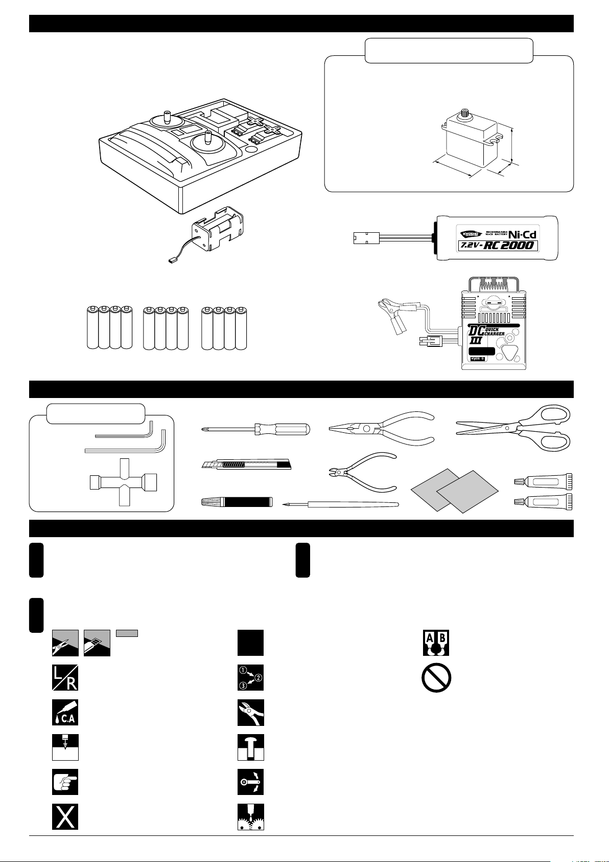
キットの他にそろえる物 REQUIRED FOR OPERATION
2チャンネル 2サーボ無線操縦機(プロポ)と電池ボックス
2 channel & 2 servo radio for R/C models, and battery box.
●このキットでは、フタバ製プロポを ベースに説明しています。
■スティックタイプ2チャンネルプロポ
Stick-type 2 channel radio
■電池ボックス
Battery Box
●プロポセットに付いている
ときは必要ありません。
If already supplied with the radio,
there is no need to purchase a
battery box separately.
■単3乾電池(送信機用)…8
AA-size Batteries
(For Transmitter) … 8 pcs.
AAAA
*プロポの取扱い方は、プロポに付属の説明書を参考にしてください。
For proper radio handling, refer to its manual.
(受信機用)…4
AA-size Batteries
(For Receiver) … 4 pcs.
AAAA
AAAA
標準以外のプロポを使用する場合
With a standard radio
●お手持ちのプロポを使用される場合は、下記の
<使用できるサーボ・サイズ>を確認してください。
If using a radio you are in possession of, check the dimensions
of its servos against the diagram below.
<使用できるサーボサイズ>
< Suitable servo dimensions >
約30mm
approx. 30mm
約40mm
approx. 40mm
■7.2Vニカドバッテリー
7.2V Ni-Cd Battery
■DC急速充電器
DC CHARGER
R
7.2V充電式ニカドバッテリー
FUSE 7.5A
WARNING HOT
Ni-Cd BATTERY
KYOSHO CORPORATION MADE IN JAPANNo.71701
WARNING HOT
7.5
DELTA PEAK AUTO-CUTOFF
E
CHARG
ART
ST
約20mm
approx. 20mm
組立てに必要な工具 TOOLS REQUIRED
キットに入っている工具
TOOLS INCLUDED
■六角レンチ
Hex Wrench
■十字レンチ
Cross Wrench
2mm
1.5mm
■+ドライバー(大、中、小)
Phillips Screwdriver (L.M.S)
■カッターナイフ
Sharp Hobby Knife
■瞬間接着剤
Instant Glue
組立て前の注意(1) BEFORE YOU BEGIN (1)
組立てる前に説明書を良く読んで、おおよその
1
構造を理解してから組立てに入ってください。
Read through the manual before you begin, so
you will have an overall idea of what to do.
説明書に使われているマーク
3
Symbols used throughout the instruction manual, comprise:
をカットする。
Cut off shaded portion.
左右同じように組立てる。
Assemble left and right sides the
same way.
2セット組立てる(例)。
Assemble as many times as specified
(here: twice).
x2
番号の順に組立てる。
Assemble in the specified order.
■キリ
Awl
■ラジオペンチ
Needle Nose Pliers
■ニッパー
Wire Cutters
■サンドペーパー
Sand Paper
■ハサミ
Scissors
■エポキシ接着剤
Epoxy Glue
セットの内容をお確かめください。万一不良、不足があ
2
りましたら、お買い求めの販売店にご相談いただくか、
当社「ユーザー相談室」までご連絡ください。
Check all parts. If you find any defective or missing parts,
contact your local dealer or our Kyosho Distributor.
エポキシ接着剤で接着する。
Apply epoxy glue.
禁止事項(してはいけないこと)。
Do not do that!
Epoxy A
Epoxy B
瞬間接着剤で接着する。
Apply instant glue (CA glue, super glue).
2mmの穴をあける(例)。
Drill holes with the specified diameter
(here: 2mm).
2mm
注意して組立てる所。
Pay close attention here!
別購入品
Must be purchased separately!
余分をカットする。
Cut off excess.
仮止め。
Tentatively tighten.
可動するように組立てる。
Ensure smooth non-binding movement
while assembling.
グリスを塗る。
Apply grease.
2
Page 3
組立て前の注意(2) BEFORE YOU BEGIN (2)
このキットには、形のちがうビスや長さがちがうビス
4
が多く入っています。原寸図で確かめてから組立てて
ください。ビス類は多めに入っているものがあります
ので、予備としてお使いください。
This kit contains many screws in and other hardware
different metric sizes and shapes. For your reference,
the figures in the manual show actual sizes. (Some
screws are extras.)
●ビスの種類 Types of screws:
ビス Screw セットビス
●サイズ例
How size of screw is given:
3x12mmビス
Screw
TPビス
Self-tapping (TP) Screw
3mm
12mm
Set Screw
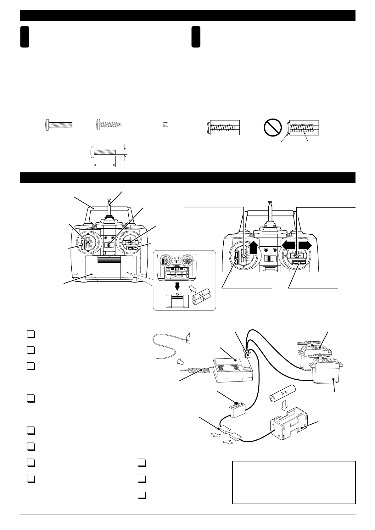
プロポの準備 RADIO PREPARATION
ハンドル
Handle
スピードコントロール
スティック
Speed Control Stick
CH-2 CH-1
スピードコントロール
トリム
Speed Control Trim
BATT.
アンテナ
Antenna
電源スイッチ
Switch
ラダースティック
Rudder Stick
ラダートリム
Rudder Trim
5
スピードコントロール
スティック
Speed Control Stick
●前進、停止の操作は
このスティックでお
こないます。
For forward move ment & stop.
CH-2 CH-1
BATT.
TPビスは、部品にネジを切りながらしめつけるビス
です。しめこみが固い場合がありますが、部品が確実
に固定されるまでしめこんでください。ただし、しめ
すぎるとネジがきかなくなりますので、部品が変形す
るまでしめないでください。
Self-tapping (TP) screws cut threads into the parts
when being tightened. Excessive force may
permanently damage parts when tightening TP
screws. It is recommended to stop tightening when
the part is securely attached or when some resistance
is felt after the threaded portion enters the plastic.
しめすぎ
Overtightened.
CH-2 CH-1
前
BATT.
進
ビスがきかない
The threads are stripped.
ラダースティック
Rudder Stick
●左右へ曲がるときの操
作はこのスティックで
おこないます。
For steering (left and
right bends).
左 右
バッテリーカバー
Battery Cover
●プロポを下の順番にしたがってセットします。
Set up a radio control system as indicated below.
各コネクターを接続する。
1
Plug in connectors.
単3乾電池をセットする。
2
Install the AA-size batteries.
送信機のアンテナを最後まで引き出す。
3
縮めて使用すると電波の到達距離が短く
なるので注意する。
Extend the transmitter antenna. If not, the
range of the transmitter will not be sufficient!
受信機のアンテナをほどく。
4
縮めて使用すると電波の到達距離が短く
なるので注意する。
Undo the receiver antenna. If not, the
range of the receiver will not be sufficient!
送信機の各トリムレバーを中央にする。
5
Center all trims. (Transmitter)
送信機のスイッチを入れる。
6
Switch on. (Transmitter)
受信機のスイッチを入れる。
7
Switch on. (Receiver)
送信機のスティックを操作しサーボが
8
作動するか確認する。
Check that the servos move according
to your inputs. (Transmitter)
受信機のスイッチを切る。
9
Switch off. (Receiver)
送信機のスイッチを切る。
10
Switch off. (Transmitter)
送信機のアンテナを縮める。
11
Retract the antenna. (Transmitter)
アンテナ
Antenna
コネクター
Connector
受信機
Receiver
スイッチ
Switch
スピードコントロールトリム
Speed Control Trim
●船が走り出さないように
このトリムで調整します。
Adjust so boat will not
speed off at once.
コネクター
Connector
CH.1
BATT
ラダートリム
Rudder Trim
●船がまっすぐ走るように
このトリムで調整します。
For adjusting straightline
running.
スピードコントロールサーボ
Speed Control Servo
CH.2
プロポセットに付属している取扱説明書も
あわせてお読みください。
In addition to this page, read the instruc-tion
manual supplied with your radio as well.
ラダーサーボ
Rudder Servo
電池ボックス
Battery Box
3
Page 4
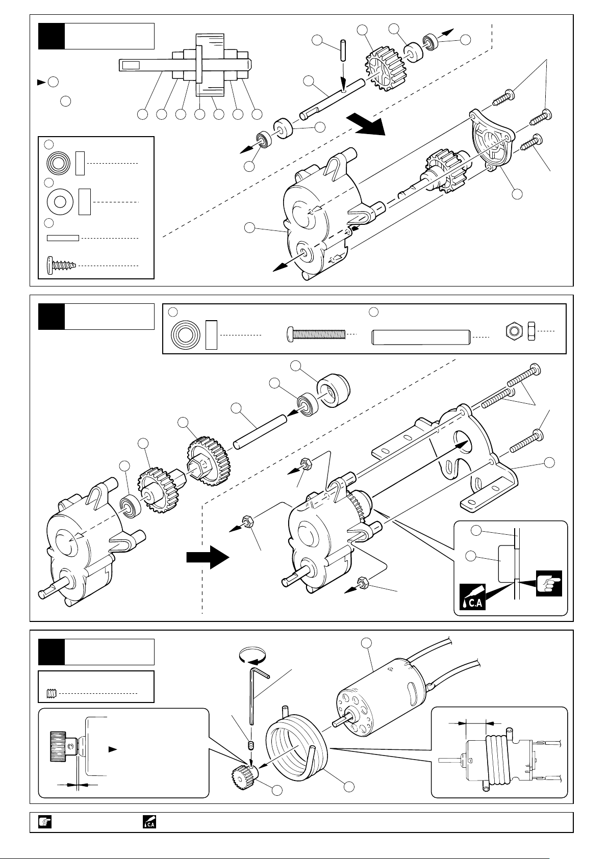
1
ギヤボックス
Gear Box
3
5
2
1
3x8mm
を奥まで入れる。
3
Make sure the Stopper
3
pin fits as shown.
1
4 x 8 x 3mm
2 4 x 9 x 4mm
Collar
3 2 x 11mm
Pin
3 x 8mm
TP Screw
ステンレスベアリング
Stainless Bearing
カラー
平行ピン
TPビス
ギヤボックス
2
Gear Bpx
4 1 2 3 5 2 1
2
2
1
6
1
3
8
5 x 10 x 4mm
ステンレスベアリング
Stainless Bearing
3 x 18mm
Screw
2
12
4
2
3x8mm
7
ビス
9 5 x 34mm
Shaft
3
シャフト
3mm
Nut
1
ナット
3
ギヤボックス
3
Gear Box
3 x 3mm
Set Screw
セットビス
8
9
3x18mm
11
10
8
3mm
13
13
3mm
3mm
12
16
六角レンチ(1.5mm)
Hex Wrench (1.5mm)
1
3x3mm
15mm
0.5mm
注意して組立てる所。
Pay close attention here!
4
平らな所にセットビス
を締め込む。
Firmly tighten the set
screw onto the flat spot.
瞬間接着剤で接着する。
Apply instant glue (CA glue, super glue).
14
15
Page 5
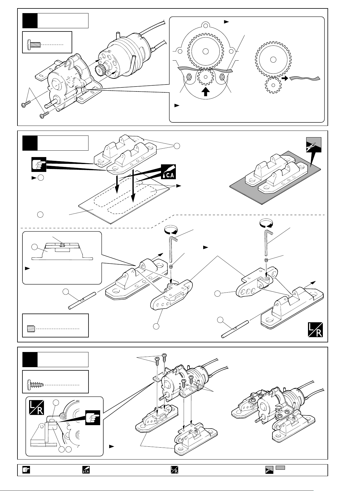
ギヤボックス
4
Gear Box
3 x 6mm
Screw
3x6mm
ビス
説明書の端をカット。
Cut a slip of paper from
a page of this manual.
2
ギヤボックス
5
Gear Box
の接着面をサンド
17
ペーパーであらしておく。
Abrade the glued surface
with sandpaper.
21
ゴムシート
Rubber Sheet
4x4mm
17
3x6mm
ギヤを押しつけながら3x6mmビスを締める。
Insert the paper between the gears and tighten
them with the 3x6mm screws.
3x6mm
17
接着面に油分や
汚れをつけない。
Glued surface should
be free from any oil
residues and dirt.
六角レンチ(2.0mm)
Hex Wrench (2.0mm)
4x4mm
向きに注意。
Note the direction.
六角レンチ(2.0mm)
Hex Wrench (2.0mm)
4x4mm
平らな面にセットビスを固定する。
Firmly tighten the set screw onto
the flat spot.
20
4 x 4mm
セットビス
Set Screw
2
ギヤボックス
6
Gear Box
3 x 8mm
TP Screw
TPビス
4
13
19
20
18
3x8mm
3x8mm
1918
注意して組立てる所。
Pay close attention here!
向きに注意。
Note the direction.
瞬間接着剤で接着する。
Apply instant glue (CA glue, super glue).
左右同じように組立てる。
Assemble left and right sides the same way.
をカットする。
Cut off shaded portion.
5
Page 6
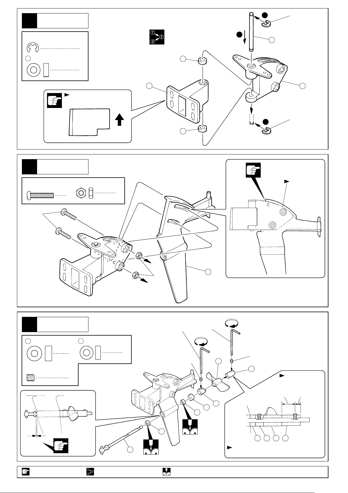
7
ラダー
Rudder
1
E3 Eリング
E-ring
E3
Eリング
E-ring
26
4 x 8mm
Metal Bushing
メタル
ラダー
8
Rudder
3 x 14mm
Screw
2
2
向きに注意。
Note the direction.
3mm
Nut
2
ナットビス
上
Top
2
22
26
26
2
25
23
3
E3 Eリング
E-ring
すき間を
あけない。
Make sure that
there is no gap.
3x14mm
ラダー
9
Rudder
2
4 x 9 x 4mm
Collar
4 x 4mm
セットビス
Set Screw
26
1
2
4 x 8mm
Metal Bushing
カラー メタル
3mm
六角レンチ(2.0mm)
Hex Wrench (2.0mm)
2
4x4mm
24
4x4mm
29
30
向きに注意。
Note the direction.
長い 短い
Long Short
28
2
26
0.5mm
注意して組立てる所。
Pay close attention here!
6
27
番号の順に組立てる。
Assemble in the specified order.
26
グリスを塗る。
Apply grease.
2
28 29 30
平らな面にセットビスを固定する。
Firmly tighten the set screw onto the flat spot.
Page 7
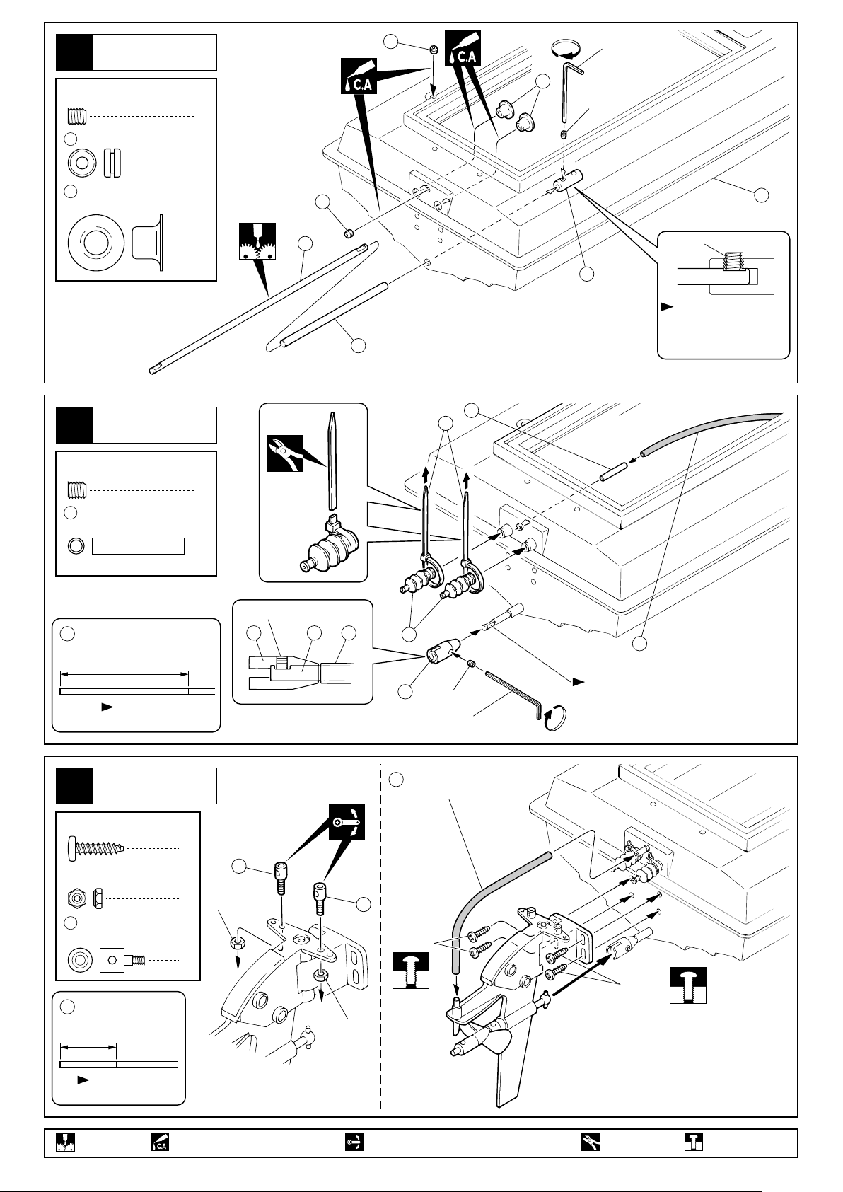
船体
10
Hull
4 x 4mm
Set Screw
31
32
セットビス
3mm
Grommet
ロッドガイド
Rod Guide
グロメット
31
六角レンチ(2.0mm)
Hex Wrench (2.0mm)
32
1
2
31
4x4mm
33
船体
11
Hull
4 x 4mm
Set Screw
41
42
セットビス
パイプジョイント
Pipe Joint
シリコンチューブ
Silicone Tube
400mm
カットする。
Cut off.
2
37
4x4mm
34
平らな面にセットビス
を固定する。
36
Firmly tighten the set
screw onto the flat spot.
41
60
1
1
4x4mm
38 37 36
39
38
4x4mm
六角レンチ(2.0mm)
Hex Wrench (2.0mm)
42
シリコンチューブ(400mm)
Silicone Tube (400mm)
平らな面にセットビスを固定する。
Firmly tighten the set screw onto
the flat spot.
船体
12
Hull
3 x 12mm
TP Screw
2mm
Nylon Nut
リンケージポスト
43
Linkage Post
42
シリコンチューブ
Silicone Tube
140mm
グリスを塗る。
Apply grease.
TPビス
ナイロンナット
カットする。
Cut off.
4
43
2
2mm
2
瞬間接着剤で接着する。
Apply instant glue (CA glue, super glue).
42
シリコンチューブ(140mm)
Silicone Tube (140mm)
43
3x12mm
2mm
可動するように組立てる。
Ensure smooth non-binding movement while assembling.
3x12mm
余分をカットする。
Cut off excess.
仮止め。
Tentatively tighten.
7
Page 8

船体
13
Hull
4 x 4mm
Set Screw
セットビス
ここでは接着しない。
Don't pour instant glue at here.
1
平らな面にセットビス
を固定する。
Firmly tighten the set
screw onto the flat spot.
六角レンチ(2.0mm)
Hex Wrench (2.0mm)
4x4mm
ギヤボックス
Gear Box
37
接着面に油分や汚れをつけない。
Glued surface should be free
from any oil residues and dirt.
船底の接着面をサンドペーパー
であらしておく。
Abrade the glued surface
with sandpaper.
船体
14
Hull
CHECK 1
>
21
船底
Bottom
船底と のすき間をあけない。
21
Make sure that there is no gap.
<
CHECK 2
21
> <
4mm
12mm
CHECK 3
が中心になるようにする。
37
Make sure that runs parallel to the center line of the boat.
><
37
37
CHECK1〜3を確認のあと、 と
船底のすき間に瞬間接着剤を流し
込んで接着する。
After positioning, pour instant
glue into the space around .
21
21
21
瞬間接着剤で接着する。
Apply instant glue (CA glue, super glue). Pay close attention here!
左右同じように組立てる。
Assemble left and right sides the same way.
注意して組立てる所。
Page 9

船体
15
Hull
42
シリコンチューブ
Silicone Tube
カットする。
Cut off.
110mm
5mm
42
シリコンチューブ(5mm)
Silicone Tube (5mm)
A5
2.6x8mm
41
31
42
シリコンチューブ(110mm)
Silicone Tube (110mm)
2.6 x 8mm
Screw
2.6mm
Nut
31
3mm
Grommet
41
パイプジョイント
Pipe Joint
ビス
ナット
グロメット
2.6mm
2
2
1
3x12mm
1
2
軽く動く位置で3x12mmTPビス4本を締める。
Tighten the 3x12 TP Screws and make sure the
easy movement of rudder to the directions as arrows show.
メカボックス
16
Radio Bpx
の接着面をサンド
44
ペーパーであらしておく。
Abrade the glued surface
with sandpaper.
1
2.6mm
3x12mm
12mm
44
21
ゴムシート
Rubber Sheet
3 x 8mm
TP Screw
46
TPビス
8 x 3 x 3.5mm
Collar
一番上の目盛に合わせる。
Align with the top mark.
カラー
6
4
49
接着面に油分や汚れをつけない。
Glued surface should be free
from any oil residues and dirt.
48
45
注意して組立てる所。
Pay close attention here!
可動するように組立てる。 左右同じように組立てる。 瞬間接着剤で接着する。
Ensure smooth non-binding movement while assembling. Assemble left and right sides the same way.
番号の順に組立てる。
Assemble in the specified order.
Apply instant glue (CA glue, super glue).
3x8mm
47
46
3x8mm
をカットする。
Cut off shaded portion.
向きに注意。
Note the direction.
46
3x8mm
上から2番目の目盛に合わせる。
Align with the second mark
from the top.
エポキシ接着剤で接着する。
Apply epoxy glue.
9
Page 10

メカボックス
17
Radio Box
50
アンテナグロメット
Antenna Grommet
51
スポンジテープ
Sponge Tape
51
スポンジテープ
Sponge Tape
すき間が無い様に貼る。
Apply sponge tape
1
around the entire rim,
leaving no gaps.
50
50
メカボックス
18
Radio Box
3 x 8mm
TP Screw
TPビス
3x8mm
ラダー
サーボ
Rudder
Servo
8mm8mm
2mm
サーボ付属
4
3x8mm
53
Supplied with the servo.
2mm
この穴を使う。
Use this hole.
39
メカボックス
19
Radio Box
54
キャップ
Cap
55
4
55
コードブーツ
Cord Boots
2
54
別購入品。 瞬間接着剤で接着する。
Must be purchased separately! Apply instant glue (CA glue, super glue).
10
55
54
54
をカットする。 2mmの穴をあける(例)。
Cut off shaded portion. Drill holes with the specified diameter.
2mm
54
Page 11

20
メカボックス
Radio Box
3x8mm
3 x 8mm
TP Screw
21
3 x 16mm
TP Screw
TPビス
メカボックス
Radio Box
TPビス
3x8mm
5
スピードコントロールサーボ
3x8mm
Speed control servo.
56
59
3x16mm
2
22
メカボックス
Radio Box
60
ナイロンストラップ
Nylon Strap
赤
Red
57
58
Receiver
電池ボックス
Battery Box
受信機
黒
Black
60
ナイロン
ストラップ
Nylon Strap
コードの出口にすき間が無い様に
先端付近をしばる。
Tighten securely with a nylon strap.
Leave no openings for water to enter
the radio box.
別購入品。
Must be purchased separately!
60
アンテナ
Antenna
60
余分をカットする。
Cut off excess.
11
Page 12

23
66
Oリング P2
O-ring P2
61
Oリング P5
O-ring P5
メカボックス
Radio Box
1
1
<OFF>
66
61
65
<ON>
67
61
66
64
65
2
スイッチ
63
ON
Switch
向きに注意。
Note the direction.
3
1
OFF
62
スイッチに付属のビス。
Supplied with the switch.
メカボックス
24
Radio Box
スピードコントロールスティック 中立
With the speed control stick in neutral.
オフ
OFF
0.5mm
スピードコントロールスティック 前進
With the speed control stick pushed up.
オン
ON
0.5mmのすき間が出来るようにする。
Ensure a gap of 0.5mm.
15mm
サーボ付属
Supplied with
the servo.
スイッチ
Switch
電池ボックス
Battery Box
プロポの説明書を参考に、
コネクターを接続する。
Connect as per radio
instruction manual.
12
25
メカボックス
Radio Box
閉まる。 開く。
Close. Open.
番号の順に組立てる。左右同じように組立てる。
Assemble in the specified order.Assemble left and right sides the same way.
別購入品。 をカットする。
Must be purchased separately! Cut off shaded portion.
Page 13

船体
26
Hull
3 x 3mm
Set Screw
セットビス
4
位置を合わせて接着。
Make sure the position is correct;
then, glue into place.
2
メカボックス
3
185mm
Radio Box
船底
Bottom
船底と のすき間をあけない。
21
Make sure that there is no gap.
同色のコードどうしをつなぐ。
Connect cords of the same
color with each other.
21
1
68
A
90°
B
A = B
角度を合わせセットビス
を締め込む。
Adjust the angle as
shown, and then tighten
the set screws.
バッテリーホルダー
27
Battery Holder
六角レンチ
(1.5mm)
Hex Wrench
(1.5mm)
3x3mm
51
スポンジテープ
Sponge Tape
2
4
接着面に油分や汚れ
をつけない。
Glued surface should
be free from any oil
residues and dirt.
シリコンチューブが折れ曲がら
42
3x3mm
70
両面テープ
Double-sided Tape
ないようにメカボックスを接着する。
Secure the radio box with glue.
Do not bend the silicone tube.
船底の接着面をサンドペーパーであらしておく。
Abrade the glued surface with sandpaper.
両面テープを半分にカットする。
70
Cut the double - sided tape in halves.
70
69
注意して組立てる所。 左右同じように組立てる。
Pay close attention here! Assemble left and right sides the same way.
瞬間接着剤で接着する。
Apply instant glue (CA glue, super glue).
番号の順に組立てる。
Assemble in the specified order.
13
Page 14

船体
28
Hull
位置を合わせて固定。
Install the battery tray
at the position shown.
69
2.6x8mm
7.2Vニカドバッテリー
7.2V Ni-Cd Battery
76
71
69
コード、シリコンチューブを の外に通す。
Leave the cords and silicon tube outside
of band .
2.6 x 8mm
TP Screw
29
3 x 8mm
TP Screw
69
TPビス
ハッチ
Hutch
TPビス
3
69
2
3x8mm
72
A-2
51
スポンジテープ
Sponge Tape
走行時のみコネクター
をつなぐ。
Connect the cords only
when running the boat.
51
A-3
3x8mm
30
A-1
キャビン
Cabin
74
をカットする。 別購入品。
Cut off shaded portion. Must be purchased separately!
左右同じように組立てる。 注意して組立てる所。
Assemble left and right sides the same way. Pay close attention here!
72
73
すき間をあけずに貼る。
Apply sponge tape around the
entire rim, leaving no gaps.
14
Page 15

31
32
キャビン
Cabin
船体
Hull
73
74
33
75
ボディピン
Body Pin
船体
Hull
75
75
曲げる。
Bend
1
35
船台
Stand
をカットする。瞬間接着剤で接着する。
Cut off shaded portion.Apply instant glue (CA glue, super glue).
15
Page 16

34
デカール
Decals
図の位置にデカールをはる。
Apply the decals to the spots indicated.
カッコの中は反対側用のデカールナンバーです。
The decal numbers between brackets are only for the opposite side.
23 11 21 33
ナンバーのついていないデカールは好きな位置に貼る。
Decals with no number apply any place.
5 7 1
27
3
25 31
9
4634
17
19 47
35
14
走航調整
Adjust Running
16
15
18
22
35
10 32
( )
44 45
4 6
26
2
24 30
42 43
( )
8
28 29
R
2048
( )
40 41
( )
38 39
( )
36 37
( )
12 13
スクリューの角度を変更する事により走航姿勢とスピードの調整を行ないます。
Adjusting the running posture and the speed by adjusting the angle of propeller.
( )
風→弱い
波→低い
Wind : light
Waves : low
風→強い
波→高い
Wind : strong
Waves : high
船首を上げたい時。
Bow will be up.
船首を上げる。
Bow will be up.
船首を下げる。
Bow will be down.
これより後ろの目盛は使用しない。
Do not adjust the rudder beyond this point.
基準位置。
Standard position.
船首を下げたい時。
Bow will be down.
すき間が無い様にする。
Make sure that there is no gap.
3x14mmビスをゆるめて調整。
Adjust the angle by loosening the 3x14 screws.
16
Page 17

取扱いの注意 OPERATING YOUR MODEL SAFELY
事故やケガ等の危険防止のため、次のことを必ずお守りください。
In order to avoid accidents and personal injury, be sure to observe the following:
●R/Cボートは、湖や河川などの水辺で楽しむものです。
操縦する方や同行の方が思わぬ事故に合わないように
注意し、必ず安全な場所で走航させてください。
With R/C boats, discover a new world of pleasure.
Wheth-er you run your boat on lakes, rivers or elsewhere, take precautionary measures to avoid accidents.
●ケガの恐れがあるので回転
部分に手や物を入れないよ
うにしてください。
Do not put your hands or
any objects into rotating
parts, as this could result in
serious accidents!
●走航直後はモーターやニカ
ドバッテリーなど熱くなっ
ているのでしばらくさわら
ない。また、連続走航はさ
せない。
Ni-Cd
ery
tt
Ba
V
.2
7
The motor and Ni-Cd
battery get hot from run-ning. Do not touch them
for a while after running.
●充電 中は、 ニカド バッテ
リー、充電器ともに発熱す
B
B
A
るので燃えやすい物の上で
の充電は火災等、事故の恐
A
TTER
TTER
Y
Y
れがありますのでおやめく
ださい。
Never put the charger and Ni-Cd battery near flam-mable material while charging as this may cause fires!
●次のような場合ショートの原因となり火災等事故の恐
れがあり非常に危険です。
Under the following circumstances, short circuits may
oc-cur and result in fires or other accidents:
●次のような時や、次のような場所では絶対に走航させ
ないでください。思わぬ事故やケガの原因となります。
For accident prevention, do not run your model under
the following circumstances:
人が多い場所。
in places where many people gather!
河川が増水しているとき、また流れが速いとき。
when rivers are swollen or their current is strong!
同じバンドの無線操縦模型がそばにいるとき。
Also make sure that nobody is using the same
frequency as you do at the same time!
01
05
プロポの電池残量が少ないとき。
with weak radio batteries!
船の動きがおかしい???とき。
when the boat behaves or operates strangely!
?
?
?
?
?
■ニカドバッテリーの分解、改造は絶対にしない。
when disassembling or modifying Ni-Cd batteries.
Never do that!
P
OWER 1
4
0
7.
0
2V
破裂危険
EXPLOSIVE
■ニカドバッテリーは有害重金属が使用されています。
火中に投げ入れて破裂すると非常に危険ですので、絶
対にしない。
Never dispose of Ni-Cd batteries into a fire, as these
can explode or emit noxious gases from heavy met-als
used in Ni-Cd batteries !
7
7
.
.
2
2
N
N
V
V
i-C
i-C
d B
d B
att
att
er
er
y
y
破裂危険
EXPLOSIVE
●走航させない時は、必ず電源スイッチを
『OFF』にし、安全のため必ずニカドバ
ッテリーのコネクターを抜き、本体より
外しておく。
発熱、発火の原因になります。
When NOT using the model, always
switch off the receiver and transmitter!
Furthermore, disconnect the Ni-Cd
確認する
CHECK
battery and remove it from the model!
This may lead to overheat and fires!
●不要になったニカドバッテリーは捨てずに販売店にお
戻しください。
Do not dispose of Ni-Cd batteries! Return them to the
retail shop!
17
Page 18

走行前のチェック PRE-RUN CHECKLIST
ゆるんでいるビスはありませんか。
プロポの電池はありますか。
ニカドバッテリーの充電はしていますか。
ラダーの動きはプロポの動きとあってますか。
スピードコントローラーの動きはプロポの動き
とあってますか。
走航場所は安全な所ですか。
近くで同じバンドで無線操縦模型をしている人は
いませんか。
ニカドバッテリーは確実に固定されていますか。
スクリューのとりつけは確実ですか。
回転部分にはグリスが塗ってありますか。
可動部分に当たる物はありませんか。
走航手順 PROPER OPERATING PROCEDURES
走航用のバッテリーを充電。
Fully charge the Ni-Cd battery.
送信機の電池をチェック。
Check the transmitter batteries
CH-2 CH-1
BATT.
Are all screws securely tightened?
Are the radio batteries fully charged?
Is the Ni-Cd battery fully charged?
Does the rudder operate according to your inputs
on the transmitter?
Does the speed controller operate according to your
inputs on the transmitter?
Is the Ni-Cd battery securely attached?
Is the running area safe?
Is nobody on your frequency when running at the
same time in the same area?
Is the propeller securely attached?
Are all rotating parts greased?
Can all moving parts move freely, without binding?
スピードコントローラーがオフであるこ
31 2
とを確認。
Ensure that the speed control servo is in
off position.
ニカドバッテリーのコネクターをつなぐ。
4
Connect the Ni-Cd battery.
受信機のスイッチを入れる。
7
Switch on the receiver
ON
走航場所が安全であることを確認。
10
Make sure the running area is safe.
船を回収する。
1
After finishing running, collect your
boat.
送信機のアンテナをのばす。
5
Extend the transmitter antenna
C
H
-
2
BA
TT
.
C
H
-
1
ラダーがプロポのスティックの
8 9
動きとあっているか確認。
Make sure the rudder operates according
to your inputs on the transmitter.
CH-2 CH-1
BATT.
左 右
送信機のスイッチを入れる。
6
Switch on the transmitter.
スピードコントローラーがプロポの
スティックの動きとあっているか確認。
Make sure the speed controller operates
according to your inputs on the transmitter.
前
進
CH-2 CH-1
走行が終わったら AFTER RUNNING . . .
受信機のスイッチを切る。
2
Switch off the receiver.
送信機のスイッチを切る。
3
Switch off the transmitter.
BATT.
CH-2 CH-1
OFF
ON
BATT.
ON
OFF
ニカドバッテリーのコネクター
4 5
をはずす。
Disconnect the Ni-Cd battery.
18
OFF
船体の汚れ水分をきれいにとる。
Remove dirt from the hull.
CH-2 CH-1
BATT.
OFF
ON
●走航させない時は、必ず電源スイッチを『OFF』
にし、安全のため必ずニカドバッテリーのコネク
ターを抜き、本体より外しておく。
発熱、発火の原因になります。
When NOT using the model, always
switch off the receiver and transmitter!
Furthermore, disconnect the Ni-Cd
battery and remove it from the model!
This may lead to overheat and fires!
確認する
CHECK
Page 19

日常の整備 EVERYDAY MAINTENANCE
ねじ、ナットのゆるみ、老化をチェック。
回転部分にはグリスを塗っておく。
コードが可動部分にこすれたりして破損している
ときは修理する。
サーボのコードや受信機のアンテナ線が破損して
いるときは、使用しているプロポメーカーに修理を
依頼する。
部品が摩耗または破損していないかチェック。
船体の汚れをとる。
船体に入っている水をぬき、よく乾かす。
故障かなと思う前に
症 状
スピードコントロールサーボが
動かない。
モーターがまわらない。
原 因
送信機の電池がない。
配線をまちがえている。
ニカドバッテリーの容量不足。
配線をまちがえている。 説明書をよく読んで配線する。
コネクターの接触不良。
モーターの故障。 モーターを交換する。
Make sure screws and nuts are securely tightened
and other parts are not worn.
Grease all rotating parts.
Repair the wiring should cords be damaged or drag
into rotating parts.
Should servo cords and the receiver antenna be
damaged, return them to the manufacturer for repair.
Make sure all parts are neither worn nor damaged.
Remove dirt from the hull.
Draw out water from inside the hull.
対 策
送、受信機のスイッチを入れる。送、受信機のスイッチがはいっていない。
新しいものに交換する。
プロポの説明書をよく読んでコネクターを
接続する。
ニカドバッテリーを充電する。
コネクターのはめこみをきつくする。
モーターはまわるが走らない。
スクリューを手でまわすと重い
またはまわらない。
スピードコントロールスティ
ックをはなしても船がとまら
ない。
PROBLEM CAUSE
Speed control servo does
not operate.
Motor does not rotate.
ジョイントがついていない。
または、ビスがゆるんでいる。
回転部分にゴミやホコリがつまっている。
リンケージの調整不良。 プロポのトリムで調整する。
ジョイントを止めているビスを
しめる。
ゴミやホコリを取り除きグリスを塗っておく。
このとき、全開に入らないようなら説明書
を読んでリンケージをもう一度調整する。
TROUBLESHOOTING
REMEDY
Switch on.Transmitter and/or receiver is not switched on.
Transmitter batteries are weak.
Improper radio installation.
Ni-Cd battery capacity is insufficient.
Improper radio installation. Correct as per instruction manual.
Loose connectors.
Motor trouble. Replace with new motor.
Replace with new batteries.
Correct as per radio instruction
manual.
Recharge Ni-Cd battery.
Make connectors tighter (e.g. with
minus screwdriver).
Motor rotates but boat will not run.
When rotating by hand, propeller
feels heavy or does not rotate.
Even when releasing speed
control, boat will not stop.
Joint is not installed.
Or, screws are loose.
Dirt entered rotating parts. Clean and regrease.
Improper linkage adjustment. Adjust speed control trim on transmitter.
Tighten screws holding joint.
Should speed controller not return to
neutral, readjust linkages as per instruction manual.
19
Page 20

スペアパーツ SPARE PARTS
品番 パーツ名 内容(キーNo.と入数) ★定価
No. Part Names
プラパーツ(A)
AL-5
Plastic Parts (A)
船体
BK-1
Hull
キャビン
BK-2
Cabin
バッテリーホルダー
BK-3
Battery Holder
デカール
BK-4
Decal
船台
BK-5
Stand
ラダーリンケージセット
BK-12
Rudder Linkage Set
パイプセット
HJ-12
Pipe Set
モーターコード(L)
SV-6
Motor Cord (L)
ニカドストラップ
1704
Ni-Cd Strap
カラーアンテナ
1705
Color Antenna
カラーシリコンチューブ
1790
Color Silicone Tube
ボディピン
1889
Body Pin
スクリュー(D42xP1.4)
94434
Propeller (D42xP1.4)
ウォータージャケット
94441
Water Jacket
防水スポンジテープ
94450
Waterproof Sponge Tape
アンテナグロメット
94851
Antenna Grommet
防水フレキシブルブーツ(L)
94852
Waterproof Flexible Boots (L)
3mmグロメット
94855
3mm Grommet
シリコンOリング(P2)赤
94871
Silicone O-ring (P2) Red
シリコンOリング(P5)赤
94873
Silicone O-ring (P5) Red
防水スイッチホルダー
94881
Waterproof Switch Holder
Description
(Key No. & Qty.)
A x 1
33
x 2
x 1
x 6
x 6
x 2
x 5
x 2
x 1
x 2
x 5
x 2
x 5
x 10
x 5
x 1
x 1
x 2
x 1
x 1
x 1
76
x 2
32
73 74
69 72
デカール一式
Decal Set
35
43 53
31 41
57 58
71
68
42
75
29
15
51
50
39
31
66
61
61 62 63 65 66 67
x 1
250
4500
1300
700
1500
1000
300
200
450
400
500
400
100
300
1200
200
200
250
200
200
200
650
★発送
手数料
200
(一律)
*FOR JAPANESE MARKET ONLY.
品番 パーツ名 内容(キーNo.と入数) ★定価
No. Part Names
防水メカボックス
94891
Waterproof Radio Box
94901-1
94901-2
94901-3
94901-4
94902-1
94905-1
94905-2
94905-3
ギヤセット
Gear Set
ギヤシャフト
Gear Shaft
スラストカラー
Thrust Collar
4mmドライブジョイント
4mm Drive Joint
V¥LCGギヤダウンAssy
94902
V¥LCG Gear Down Assy
プラパーツ(V¥LCG / Fマウント)
Plastic Parts (V¥LCG / F Mount)
SPアウトドライブAssy
94905
SP Out Drive Assy
ラダージョイントセット
Rudder Joint Set
4mm
リバーシブルストッパーセット
4mm Reversible Stopper Set
SPアウトドライブラダー
SP Out Drive Rudder
接着ゴムシート
94920
Rubber Sheet
ステンレスベアリング 4x8x3
94948
Stainless Ball Bearing 4x8x3
ステンレスベアリング 5x10x4
94950
Stainless Ball Bearing 5x10x4
TCスタンチューブセット(285)
94997
TC Stern Tube Set (285)
スポンジテープ(1mm)
96441
Sponge Tape (1mm)
4x8mmメタル
96480
4x8mm Metal
モータースイッチ(S)
96551S
Motor Switch (S)
キットの部品の一部にはスペアパーツとして販売していない物があります。
京商ではオプションパーツを販売していますのでお買い求めください。
Some of the parts included are not available as spare parts. Purchase optional parts instead.
Description
(Key No. & Qty.)
49 50 56 61 62 63 64
65 66 67
44 45 47 48 51
39 46 55
5
3 4 9 x 1
2 x 10
34
3 4 5 6 7 9
12 13 18 19 21 34
1 2 8
18 19
2
30 38
27 38
28 30
22 23 24
21
1 x 2
8 x 2
34 36 37
70
26
59
x 1
x 2
x 4
54 60
10 11
x 1
x 1
10 11
x 1
17 20
x 2
x 1
17 20
x 2
22 23 24 25 27 28
x 1
26
x 4
x 1
x 1
x 1
x 4
x 1
x 12
x 4
x 1
x 8
2500
300
200
200
200
2800
500
2000
1000
200
500
600
700
700
1200
300
400
900
★発送
手数料
200
(一律)
20
Page 21

オプションパーツ OPTIONAL PARTS
品番
No.
Kスピード
70875
ヘリスペシャルモーター
K Speed
Heli Special Motor
パーツ名 内容
Part Names Description
16
と交換, ベアリング入14ターン
instead of ,
16
Ball Bearing.
★定価
6000
★発送
手数料
200
(一律)
品番
No.
モーターブラシクーラー
94801
Motor Brush Cooler
*FOR JAPANESE MARKET ONLY.
パーツ名 内容
Part Names Description
オプションモーターの水冷用
for water-cooled motor
specifications.
★定価
2800
★発送
手数料
200
(一律)
フラップセット
94301
Trim Tab Flap Set
金属3枚スクリュー
94435
(D37xP1.4)
Metal Propeller
(D37xP1.4)
MEMO
走航姿勢調整用
for adjusting boat position.
29
と交換, 1ヶ入
instead of , 1 pcs.
29
O
Y
S
K
H
O
800
2800
94948
94949
W-0117
~
W-0125
ステンレスベアリング 4x8x3
Stainless Ball Bearing 4x8x3
ステンレススラストベアリング 4x9x4
Stainless Thrust Ball Bearing 4x9x4
ハードピニオンギヤ 48P
Hard Pinion Gear 48P
(17T ~ 25T)
と交換, 2ヶ入
26
instead of , 2 pcs.
と交換, 1ヶ入
2
instead of , 1 pcs.
14
instead of , 1 pcs.
26
2
と交換, 1ヶ入
14
ハードアルマイト
Hard Anodized
700
500
500
21
Page 22

*発送手数料は2000年1月1日現在のものです
"KyoshoDirect‑Mail‑Parts‑Order‑System"isavailableonlyforJapanesemarket
京商スペアパーツ・オプションパーツの購入方法
これらの購入方法は日本国内に限らせていただきます
部品を
こわしちゃった
●部品をこわしたり、なくしてしまった場合でも
スペアパーツやオプションパーツを購入し、
元どおりに直す事ができます。
●パーツはお 店で直接購入していただくか、
お店に行けない場合は郵便を利用して京商
から通信販売で購入できます。
●京商では電話での直接のご注文は取り扱って
おりません。ご了承ください。
1.まずはお店でお求めください
まずは、お近くのお店か、この商品をお買い求めいただいたお店にご
来店下さい。ご希望のパーツの在庫があれば即購入できます。その際
に組立/取扱説明書をお持ちになると購入がスムーズになります。
お店で在庫切れの場合でも京商の『パーツ直送便』
※
でお店から京商へ申し込めます
購入方法による手数料、お届け日数のめやす
購入方法 発送手数料
お店で
お店に在庫がない場合は
パーツ直送便で
お
店
に
現金書留で
行
け
な
い
場
郵便振込で
合
※お届け 予定日 数は夏・冬期休 業また は交通事情等運 送上の 理由
により遅れる場合がございます。
不要
200
200
円
円
お届け予定日数
日
3〜4
日
6〜7
日
10〜12
お店でご希望のパーツがたまたま品切れだった場合でも、京商の『パーツ直送便』※を利用すればその場で注文でき
ます。『パーツ直送便』は、お店に備え付けのパーツ直送便注文用紙にご希望のパーツの品番や数量等、必要事項
をご記入の上、お店に代金をお支払いいただければ結構です。3〜4日でお客様のご自宅か、お店にお届けします。
発送手数料が不要で早く着くお得なシステムです。
※一部取り扱っていないお店もございます。
パーツ直送便
注文用紙に『品番』
と必要数を記入。
パーツ直送便取り扱い店は
このステッカーが目印
2.お店に行けない場合は
次の2つの方法で京商から通信販売で購入できます
パーツ直送便の
注文用紙といっしょに
代金をお店の人に
払おう!
お店に行けない場合は郵便局から申し込んでいただくようになります。
発送手数料
円
1
現金書留で京商へ申し込む
必要事項を記入した用紙と代金を現金書留
にて京商までご送金ください。代金は次の
とおりとなります。
200
お届けまで
日
6〜7
2
郵便振込で京商へ申し込む
郵便局で払込用紙に必要事項をご記入のう
え、代金を郵便振込にて京商までご送金く
ださい。代金は次のとおりとなります。
●代金は、スペアパーツの定価の他に発送手数料(一律200円)と消費税がかかります。
●代金の計算方法代金=(スペアパーツの定価の合計+発送手数料200円)×消費税1.05(1円未満は四捨五入)
発送手数料は
不要
3〜4日でお客様の
ご自宅かお店に
お届けします。
発送手数料
円
200
郵便振込のほうが
現金書留より郵便料金が
安いね。
お届けまで
日
3〜4
お届けまで
10〜12
日
(1)
名
氏
(2)
号
話番
電
号
番
郵便
所
住
名
ツ
パー
番
品
量
数
243 0034
神奈川県厚木市船子153
京商株式会社
ユーザー相談室
TEL.046‑229‑4115
(1)メモ用紙に氏名・電話番号・郵便番号
住所(電話番号は登録・発送をスムーズに
するためのものです。必ずご記入ください)
と注文するパーツ名・品番・注文数を必ず
記入して、(2)お間違えのないよう代金と
いっしょに郵便局よりご送金ください。
・
《現金書留宛先》
〒243‑0034神奈川県厚木市船子153
京商株式会社ユーザー相談室
Tel.046‑229‑4115
《払込用紙記入例》
(1)
払 込 取 扱 票 払込票兼受領証
00
口座番号 (右詰めにご記入ください)
※ ※
0 0 2 1 0 4 4 7 2 7 1
加
各
※
入
票
者
の
名
京商株式会社
※
印
※
欄
は
品番 パーツ名 数量
通
払
(3)
1901 ベアリング 2
込
人
信
に
発送手数料
お
い
(例)
消費税
(部品+発送手数料合計金額x5%)
欄
て
記
合計
載
し
て
払
く
だ
込
(郵便番号 )
さ
※
人
い
住
所
氏
名
裏面の注意事項をお読みください。(郵政省)
(2)
(電話番号 ‑ ‑ )
金
額
料
金
千 百 十 万 千 百 十 円
1 6 8 0
殊 扱
特 取
1,400
200
80
1,680
(4)
受
付
局
日
附
印
(1)
切
り
取
ら
な
い
で
郵
便
局
に
お
出
し
く
だ
さ
い
記
載
事
項
を
訂
正
し
た
場
合
は
そ
の
箇
所
に
訂
正
印
を
押
し
て
く
だ
さ
特殊取扱
い
口
座
番
号
加
入
者
名
金
額
払
込
人
住
所
氏
名
料
金
(消費税込み)
※
0 0 2 1 0 4
右詰めにご記入ください
※
4 7 2 7 1
※
京商株式会社
千 百 十 万 千 百 十 円
※
1 6 8 0
※
(2)
受付局日附印
円
(1)口座番号:00210‑4‑47271
加入者名:京商株式会社
(2)あなたの 氏名・電話番号・郵便
番号・住所 を必ず記入してくださ
い。(電話番号は登録・発送をスム
ーズにするためのもの です。必ず
ご記入ください)
(3 )注文 する、 品番・パー ツ名・注
文数を必ず記入してください。
(4)お間違えのないよう合計金額を
記入のうえ、ご送金ください。
京商株式会社
〒243‑0034神奈川県厚木市船子153
●お問い合わせはユーザー相談室まで Tel.046‑229‑4115 受付時間:月〜金曜(祝祭日を除く)10:00〜18:00
Page 23

TheservisementionedbelowisavailableonlyforJapanesemarket.
組立や、操作上で不明な点のお問い合わせ方法
これらのサービスは日本国内に限らせて頂きます
組立てたり、操作してみて上手くいかない点などございましたら、ご購入いただいた
販売店または、京商ユーザー相談室へお問い合わせください。
京商ユーザー相談室へお問い合わせの際は、お電話いただくか、下記のお問い合わせ
用紙に必要事項をご記入のうえ、
京商へのお問い合わせ先→「京商ユーザー相談室」
京商にお問い合わせの際は、「京商ユーザー相談室」にご連絡ください。
お問い合わせの際は、お手元に商品や組立/取扱説明書をご用意のうえ、組立/取扱説明書のページ数,行程番号, 部品番
号(キーNo.)を用いるなど、なるべく具体的にお知らせください。
電話でのお問い合わせ:
ファックス
でのお問い合わせ:
046‑229‑4115
046‑229‑1501
ファ ッ クス
電話でのお問い合わせは、月曜〜金曜(祝祭日を除く)10:00〜18:00。
ファックスでは、24時間お問い合わせの受付をして居ります。回答は、翌営業日
以降となる場合があります。営業日:月曜〜金曜(祝祭日を除く)
または郵便でお送りください。
郵便でのお問い合わせ:
〒243‑0034神奈川県厚木市船子153京商株式会社ユーザー相談室
キリトリ線
お問い合わせ用紙
お問い合わせ用紙は、フ ァ ッ ク ス または郵便でお送りください。回答方法は、京商で検討のうえ考慮させて頂きます。
郵送の場合は、お問い合わせ用紙のコピーを保管してください。
商品No.
ご購入店
ご使用
プロポ
ご氏名
ご自宅
住所
ご自宅の
連絡先
平日の昼間に
可能な連絡先
月曜〜金曜(祝祭日を除く)10:00〜18:00で電話連絡可能な時間帯: 頃
40901
店名
フリガナ
〒___−____
電話
電話
商品名
()
電話
都道
府県
EPブルーストリーク800
都道府県
ご使用
モーター
ファックス
ファックス
受付No.(京商記入欄)
性別
生年
月日
ご購入
年月日
男/女
大正/昭和/平成
年月日
R/C歴
約年
年月日
お問い合わせご記入欄:
組立/取扱説明書のページ数や部品番号(キーNo.)を用いるなど、なるべく具体的にご記入ください。
 Loading...