

Kyosho dodge ram truck Assembly And Operation Manual
•
ASSEMBLY AND OPERATION
MANUAL
\ \
' I
INDEX
BEFORE BEGINNING TO BUILD ........................................................................................................................ 2
SAMPL.E s·TEP .................................................................................................................................................... 3
REQUIRED ITEMS ...................................................................... ........................................................................... 4
'
WARRANTY INFORMATION ............................................................................................................................... 5
PREPARING
THE
RADIO SYSTEM .................................................................................................................... 5
ASSEMBLY
···········································
·······
·····
···.fl····
···
-;;·
·················································································6
OPERATIONAL SAFETY AND MAINTENANCE : •.•....... ::: ..•... : ••.............................•.•....................................... 30
..
...
•
KYOZ7621 No. 31751
' .
c Copynghl 1997 3007112
•
IMP
ORT
ANT: PLEASE
READ
THROUGH THE
ENTIRE
INSTRUCTION MANUAL BEFORE BUILDING THE DODGE
RAM TRUCK.
We
want
your
experience
of
building
this
model
to be a
success. So before you remove any
parts from their packages
and begin assembly:
• Read through the entire manual carefully
to
make sure that
you are thoroughly acqualnled with the model.
•
II
lor
any reason you think this model may not be for you,
return It Immediately.
Please
Note
: Yo
ur
hobby dealer
cannot
accept a mo
del
kit
for return aft
er
assembly
has begun.
• The Kyosho Dodge Ram Truck is a sophisticated nitro-power
ed
4WD
monster
truck
with
a reversing transmission. Nitro-powered
RIC
vehicles are no more difficuH to build and operate than
electric RIC vehicles. They do require a
lew
different building
procedures than electrics. II you follow the directions closely,
the Kyosho Dodge Ram
Truck will provide many years
of
car
crushing enjoyment.
This
Kyosho
Instruction
manual
uses a cross-reference
system to help you locate all of the bagged parts. DO N
OT
open each bag and dump out the parts. Carefully remove the
header card from the bag a
nd
discard the staple. Slip the
header card into the bag or tape
it
to the outside of the bag so
that the bag number shows. This
will help you fi
nd
parts when
you need them.
REMOVE THE
HEADER
CARD
SLI
P CARD
I
NTO BAG
OR
TAPE
TO
OUTSIDE
PARTS IDENTIFICATION
A complete list of replacement and optional parts is included In
the pullout
section
of this manual. II you need to replace a
part, consult this guide f
or
the manufacturer
's
sto
ck
number
lor the
items
needed. In the left margin
of
each
page
of
instructions you will find a directory
of
small parts that will be
used in each step. For ease of identi
fi
cation, these parts are
shown actual
size, enabling you to place t
he
part directly
on
the picture to ensure you have selected the appropriate part.
Key Number
Part Name
Qua
ntity Used
2
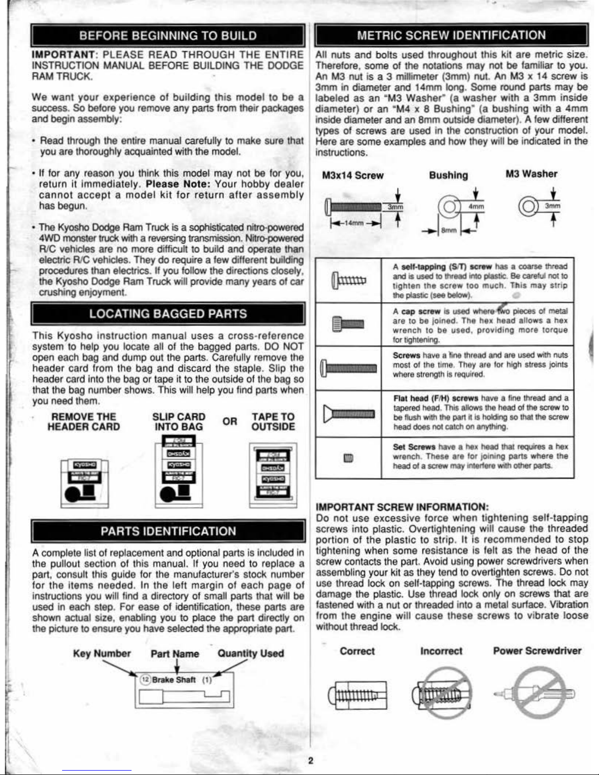
All
nuts
and bolts used throughout this kit are
metric
size.
Therefore, some
of
the notations may not be familiar to you.
An M3 nut
is
a 3 millimeter (3mm) nut. An M3 x
14
screw
is
3mm in diameter and 14mm long. Some round parts
may
be
labeled as an
"
M3
Washer" (a washer
with a 3mm inside
diameter) or an "
M4
x 8 Bush
ing'
(a bushing w
ith
a 4
mm
Inside diame
ter
and an Smm outside diameter). A few different
types of screws are used in the construction
of
your model.
Here are some examples and how they
will be indicated in the
Instructions.
M3x
14 Screw
Oa!NIIi!IMQIIM
Dfil!!b!!N!!!M!!!U!
d
Bush
ing
M3 Washer
A sell-tapping (SIT)
sc..w
has
a coarse
lh<oad
and
Is U$8d
10
lh<oad
Into pjaslic.
Be
care!\1
nolto
ti
ghten
the
screw
loo
much.
This
may
str
ip
lhe
JQ$1ic
(
see
below
).
A c:ap screw
Is
used
-•
pieces
of
melal
are to
be
joined. The hex head allows a hex
wrench to
be
used,
providing
more torque
for
tightening.
Screws
have
a line t
hread
and
are
used
with
nuts
most
of
the lime.
They
are
for
high stress join
ts
wtleca
strength Is
required
.
Rat head
(FIH)
scrowa
have a fine
thread
and
a
tlpllred
heed.
This
allows
the
head
of
the
screw
to
be
flush with the pan h Is holding
so
thai the
screw
head
does not
catCh
on anything.
Set Scrowo have
a hex head thai requires a hex
wrench. These
are
for
J
oinJ~
pans
where
the
head
of
a
screw
may
lnle<toro
with other pans.
IMPORTANT SCREW INFORMATION:
Do not
use
excess
ive
force when tightening sell-tapping
sc
rews into plast ic. Overtightening will cause the threaded
portion
of
the plas
tic
to
strip
. It
is
rec om
mended
to
stop
tightening when some resistance
Is felt
as
the head of the
screw contacts the part. Avoid using power screwdrivers when
assembling your kit as they tend to overtighten screws. Do not
use thread lock on self-tapping
sc
rews. The thread lock
may
damage the plastic. Use thread lock only
on screws that are
fastened with
a nut
or
threaded into a metal surface. Vibration
from
the
engine
will
cause
these
scre
ws
to
vibrate loose
without thread lock.
Correct
Incorrect
Power
Scre
wdriv
er
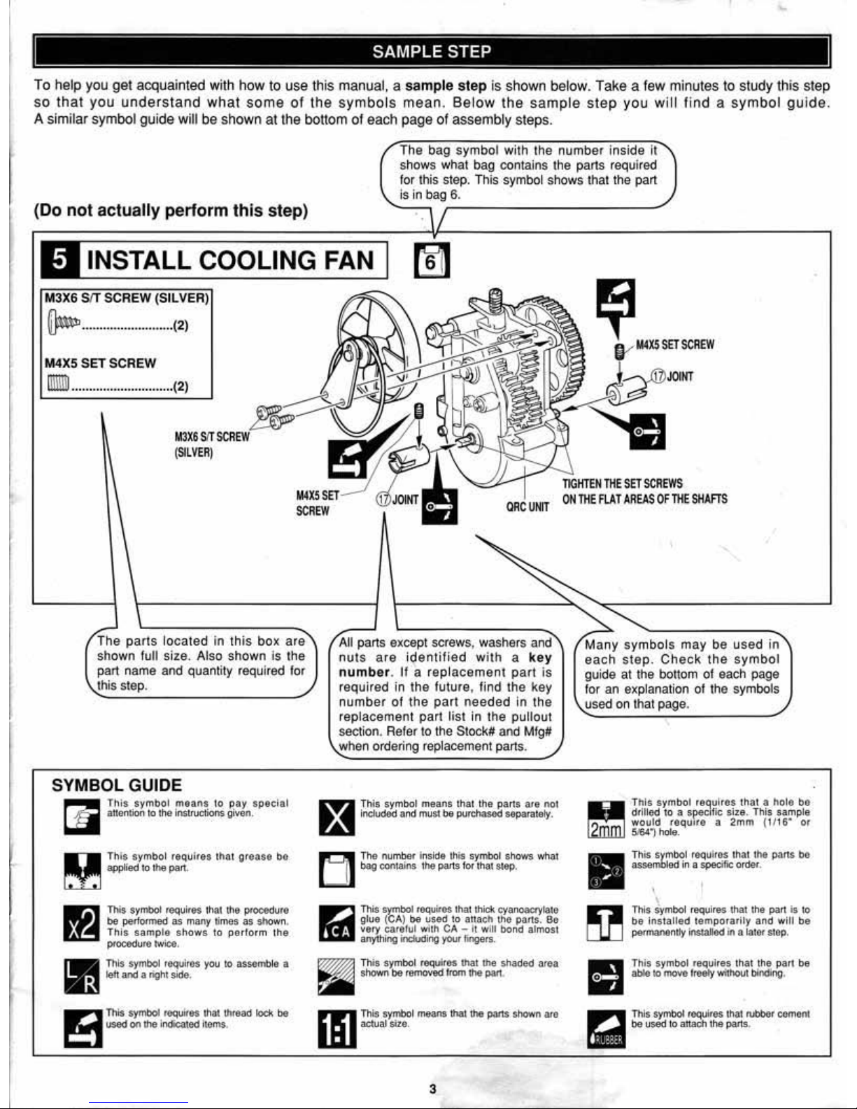
To he
lp
you get acquainted wi
th
how
to use this manual, a
samp
le
step
is
shown below. Take a few minut
es
to study th
is
step
so that
you
understand
what
some
of the symb
ols
mean. Be
low
the
samp
le
step
you
will find
a s
ymb
ol
guide
.
A
similar
symbol guide will be
shown
at
the bottom
of
each
page
of assembly steps.
(Do
not
actu
ally perform
thi
s step)
The bag symbol with the numb
er
insi
de
it
sh
ows
what bag oontains the parts
required
for this step. This symbol shows that
the
part
is
In
bag
6.
,-
--
-------------/
INSTALL COOLING FAN
M3X6
SIT
SCRE
W (SILVER)
~
.......................... (2)
M4X5
SET
SCREW
ll1ll11J
............................. (2)
M3X&
SIT
SCREW
(SI
LVER
)
The parts located
in this
box are
shown
fu
ll
size. Also shown
is
the
part name and qu
an
tity requi
red
for
this step.
SYMBOL GUIDE
~
Th
is
symbol means
to
pay special
~
attention to the Instructions given.
D This symbol requires thot grease be
m applied 10
the
part.
This symbol requires that the ptooeduro
be
perlormed as many times as shown.
This
samp
le
shows
to
perform the
ptOOOduro
twice.
-
This
symbol !&quires
you
to
assomb
le a
111,3
left
and
a right side.
All parts except sctews, washers and
n
uts
are ident
ifi
ed w
ith a key
number. If
a rep lacement
part
is
required in the future, find the key
number of the part needed
In the
replacement part
li
st
in the pullout
section. Refer to
the
Stock# and Mfg#
w
hen ord
ering replacement parts.
m
Th
is symbol
means
that
the
pans
are
no1
m
includOd
and
must
be
purchas.od
separatoly.
A The number inside this symbol shows whaJ
1-!J
~
con1ain~
t
he:
paris for that step.
This symbol roq
uifOS,
that thick cyanoacrylate
g.
lue
(CA)
be
u"Sed
to
auach
lhe
part$, sc
very
carelut
with
CA
- h
wil
l bond al
mo$1
anything incfuding your fingers.
This
symbol req
uires
that
the shaded area
shown
be
""""""
from
<he
pao.
Ill
This
syrri>ol
means
that the
p;II1S
shOwn
arc
actual
s1zo.
3
TIGHTEN
THE
SET
SCREWS
ON
THE FLAT
AREAS
OF
THE
SHAFTS
Many symbols may be used in
each
step.
Check the
symbol
guide at the bottom of each page
for
an
explanation of t
he
symbols
used on that page.
Th
is
sym
bol requhos
that a ho
lo
bo
drilled
to a spec•flc
size. This
sample
would requ
1t0
a
2mm
(1/1
6.
or
51641hote.
II
Th
is
$ymb01
r&quiros
tha
t t
he
parts
bO
assembled
in a specific order.
' I
This symbol requires that the
part
is to
be i
ns
talled
temporarily
and will
be
pori'I"'M8ntly inslalled
in
a
to:~tor
step,
- This
symbol requires that
the pan
be
1111:1
abl& ~ move fre
ely
v.iltiOut
binding
.
P.J
This
symbOl roqultOS that tubber cement
-
be
used
to attaoh the parts.
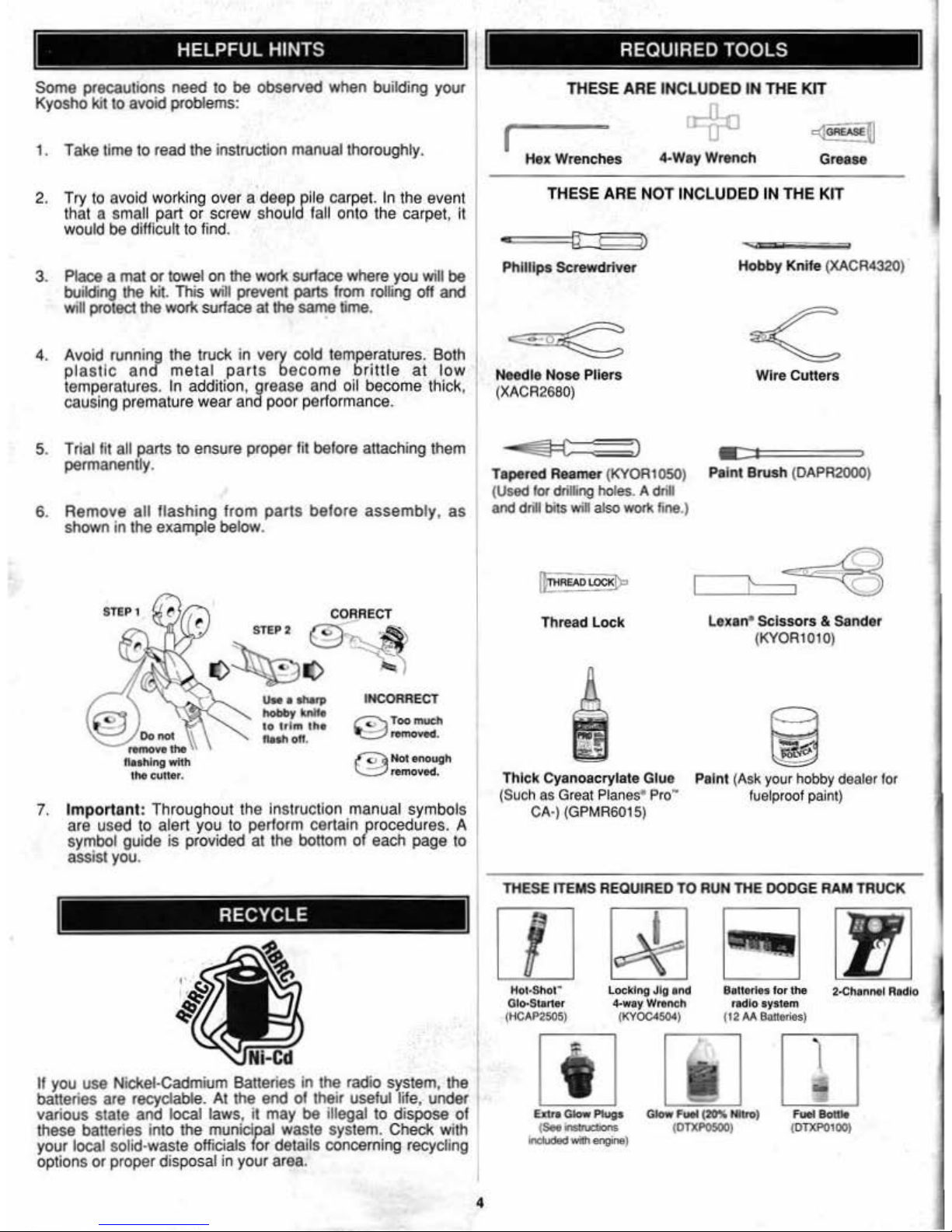
Some precauti
ons
need to
be
observed when building your
Kyosho
kit
to
avoid
problems:
1. Take time to read the instruction manual thoroughly.
2.
Try
to avoid working over a deep pile carp
el.
In
the
eve
nt
that a small part
or
screw shou ld fall onto t
he carpel, it
would
be
difficu
lt
to find.
3. Place a mat
or
towel
on
the work surface where you will
be
building
the
kit. This will prevent parts from rolling off and
will protect the work surface
a1
the
same
time
.
4. Avoid running the truck in very cold temperatures. Both
plastic
ancf meta
l parts
become brittle
at
low
temperatures. In addition, grease and oil b
eco
me thick,
causing premature w
ear
and
poo
r performance.
5. Trial fit
all
parts to ensure proper fit before attaching them
permanently.
6.
Remove
all
flashing
from
parts
before
assembly, as
shown in the examp
le
below.
STEP 1
®
Oono4
I
remove
the
1\
flashi
ng
with
l
ht
ev"er
.
UN
llhii'P
hobby Mite
to
trim
the
flllhoH
.
INCORRE
CT
~
Too
much
~.-.moved.
~
Not
enough
\...=;:/removed.
7.
Important
: Throughout the instruction manual symbols
are used to alert you to perform certain procedures. A
symbol guide is provi
ded
at
the bottom
of
each page to
assist you.
If you
use
Nickel-Cadmium Batteries in the radio system , the
batteries are recyclable.
At
the
end
of their useful life, under
various state
and
local laws, it
may
be
illegal to dispose
of
these batteri
es
into the municipal waste system. Check with
your local solid·waste officials for details concerning recycling
options
or
proper
dis
posal in your area.
4
TliESE
ARE INCLUDED
IN
THE KIT
c@§]l
(
Hex
Wrenches
4-Way Wrench
Grease
THESE ARE NOT INCLUDED
IN
THE
KIT
-
Phillips Screwdriver
Needle
Nose Pliers
(X
ACR2680)
~
:)
Tape
red
Reamer
(KYOR1050)
(
Used
for
dri!Dng holes. A drill
and dnll bits win also worl\ fi
ne
.)
IF
•EAD
LOCK[l:o
Thread Leek
Thick Cyanoacrylate Glue
(Such
as
Grea
t Planes•
Pro
·
CA
·) (GP
MR6
015)
.......
.
Hobby Knife (
XACR4320
)
Wire Cutters
• •
Paint
Brush (DAPA2000)
Lexa
n'
Scissors & Sander
(KY0Rt010)
Paint
(Ask
your hobby dealer
for
fuelproof p
aint)
TH
ESE ITEMS REQUI
RED
TO
RUN
THE
DODGE RA.M TRUCK
,
Hot-Shot"
Glo-S
tarter
(HC
AP250S
)
locking J
ig
and
4·way Wrtneh
(KYOC4504)
Extra
Gaow
Pl~s
(
SOo
..............
InCl
uded
Mh
engine)
Ballo
rte
s tor the
2-Chcmntl R
adi
o
radio
system
(1
2M
Batt&ri&s)
full8ottlt
(
OTXPOIOO
)
WARRANTY INFORMATION
-
--
•
For
90 days after
you
purchase
your
OOOGE
RAM
TRUCK.
Kyooho
will eith
er
rep:tlr
or
replaCe,
at
no
chrugo.
any
inoorr
OC11y
made
part
.
•
Make
"'re
you
SAVE
THE
RECEIPT
OR
INVOIC
'E you wert givvn
when
you
bough!
,.,... ,_,
11"1
,.,... proof
of
.,...-
•
and
we
"""t
oee ft bolore
we
ean
honor
me
w
3IT'IJI'tri
.
To
oond
Y'OUf
~Rom
Trud<
0\lor ._...-eel under
wwrar«y.
you
shoiAcl
send
your
truck
to
Ky
01110"o1Wtllotlzed
U.S. r.pair lacllly:
Hobby
So.vl*
1610 Intersta
te
Drive
Chin1>aign
. -
6t82t
Ml.SeMco~
Pnot>e
: (2t7)398-0007 9;
00..,._. 5:00• ....
Centrall'lmeM·F
For
detai
ls
on
your
telurn,
be
sure
to follow steps
1·4
under
tho
~Repa
ir
Sttvlees
Available
Anydme·
section.
Umh
of
01"
LlabMity
:
OUr
~
..-
tllio
Wlllfa/ty
Is
liritAod
10
the
repair
or
replacemerd
by
Hollby
SoMces of
defeetMO
patti
and
does
noc
1nc1u<1e
cos! ol
shipping
to
uo.
Hobby
Services
does
pay
!he
&hlpl)ing
expense
to"''"'"
warranty
items
to
you.
Ex
clu
sion
and/or
Voida
nce of
Warra
nty:
Th
is
warranty
doe$
not apply
to
damago
or
detects resulting
hom
misuse
.
- service.
damage
in
$hipmenl.
dalnlge
resulling
from
a
cnsh
01
damage
coiJSOd
by
the
banorieo.
The
warramy
Is
Wild
d
the
modol
ls
-.
allered
. 01
ropalrwcl
by
anyone -
111an
.-,.
SoMcos.
This
warranty
giws
you
spec
mc
legal
riGhts. and
you
may
have
ott'ler
rights
11\at
vary
from
state
to
&tate-
within
lhe
U.S. We are
sorry,
but
wo
cannot
be
responsib
le
for
crash dam
age and/o
r
resutdno tos.s
of
lhe truck.
onglne. radio. acce,SOl
les.
etc
.
Rep•lr
Seorvlcea
Available
AnytiiTlt':
After
1ho
904af
wam~nty
ho$
t>q>lrod,
you
can
s~
ll
hovo
your
Dodg
e Rllm
Truck
repaired lor a
lmal
chatgo
by
the
OJqlerts
at
Kyosho'& authorized U.S.
repa;r
ladlty
. Hollby
5eMces.
01
the
oddfe&&listod
under W""""'Yinlormalion.
•
To
speed
up
1ho
repair
procosa. please
follOw 111o
in&lrueli
o"' lslod
belOw
:
1.
Under
all
clrcums
tanoes. r&tum the ENTIRE
system
:
truck
and radio
.
2.
Make
su
re lho
transminer
is
wmod
oft
and
a1
baUOfles
are
d'osconnodod.
and
alluel
io
-!rom
lhe ,.,.,..,.,._
3.
Send
wriuen lnllr
uctfons wh
lch
include
: a list of
all
items
returned. a
THOROUGH explan'a.tion
ol the
prOblem
and tho
a.erv
iee
needed, and
your
phone
number
whefe
you
can
be r
eached
during
the
day.
II
you
expect
you
r
repa
ir
10
be
covered
under
warranty, be
sure
to
include
proof
of
date
of
purchase (your
51<>fe
,.,.,.,.,. « purcho5e
involc:e
).
4.
A/sQ-
yoour
lui
return
add<
....
Repa
ir ch<lrg"
and
postage
may
be
prepaid
or
billed C.O.D. All r
ep;ol
rs shipped
outside
the Unltod
States
must
be
prepaid
In U
.S. funds only.
Spedllcotlon
'""
DHaiptlon
Chango&
All pidutos, doscr1piJons
and
specillcalion$ lou>d 0\
tllio
inslruc1oon
manual
are
subiect
to
change without notice.
Kyosho
ma
ln~al
ns
no
responsibili
ty for
inadverte
n1
&f'rors
In
t.his
manu
al
• ,
----------·
------------------------------------ -------------------
~
a 4·
AA
Batteries
n Receiver
-
SWitch
Receiver Ba«ery Hold
er
fJ
Anlenna
Transmitter
8·AA Batteries
Servo
Arm
R
e<;eiver
Steering
Servo
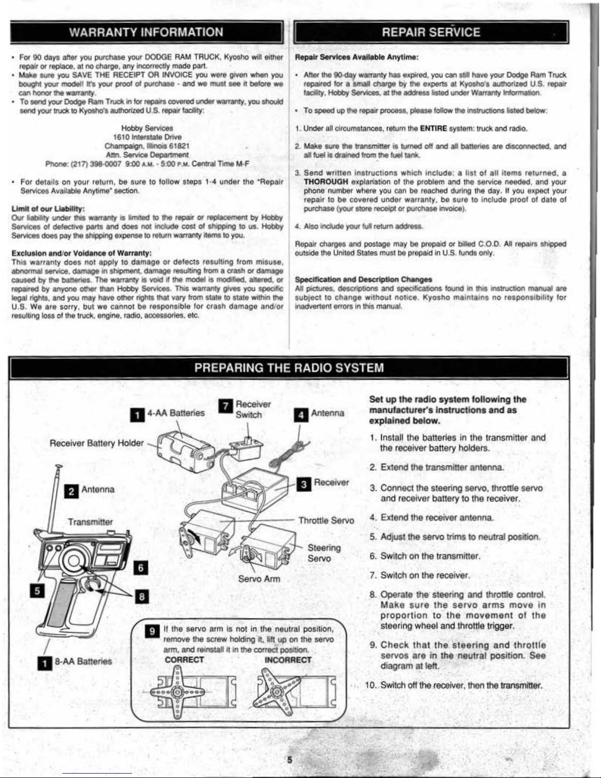
IJ
II
lhe
servo
arm
Ia
no~
in
the
neutral
Pos
lli
on,
remove
the
scre
w
holding 'h,
lih
up
on
the
servo
arm
. and
relnslall
h in the
COtTlld
position.
.•
CORRE
CT
INCORRECT
Set
up
the
radio
system following
the
manufacturer's
Instructions
and
a.s
explained
belo
w.
1.
Install the batteries In the transmitter and
the
receiver battery holders.
2. Extend the ttansmiher antenna.
3.
C<l
nnee1
the steering servo. throttle servo
and
receiver battery to the
re<:eiver
.
4.
Extend the receiver
antenna
5. Adjust
the
servo trims
to
neullal position.
6. Switch on lhe lransmltter.
7. Switch on
lhe
receiver.
8. Operate
tile
steering and throttle control.
Make sure
the
servo
arms
move
in
proportion
to
the
movement
ol
the
. steering wheel and throtlle trigger.
9.
Check
that
the steering
and
throtlle
servos
are
in
the
·neutral
position. See
diagram
at
left.
1
o.:
Switch
off the receiver, then the transmitter .
•
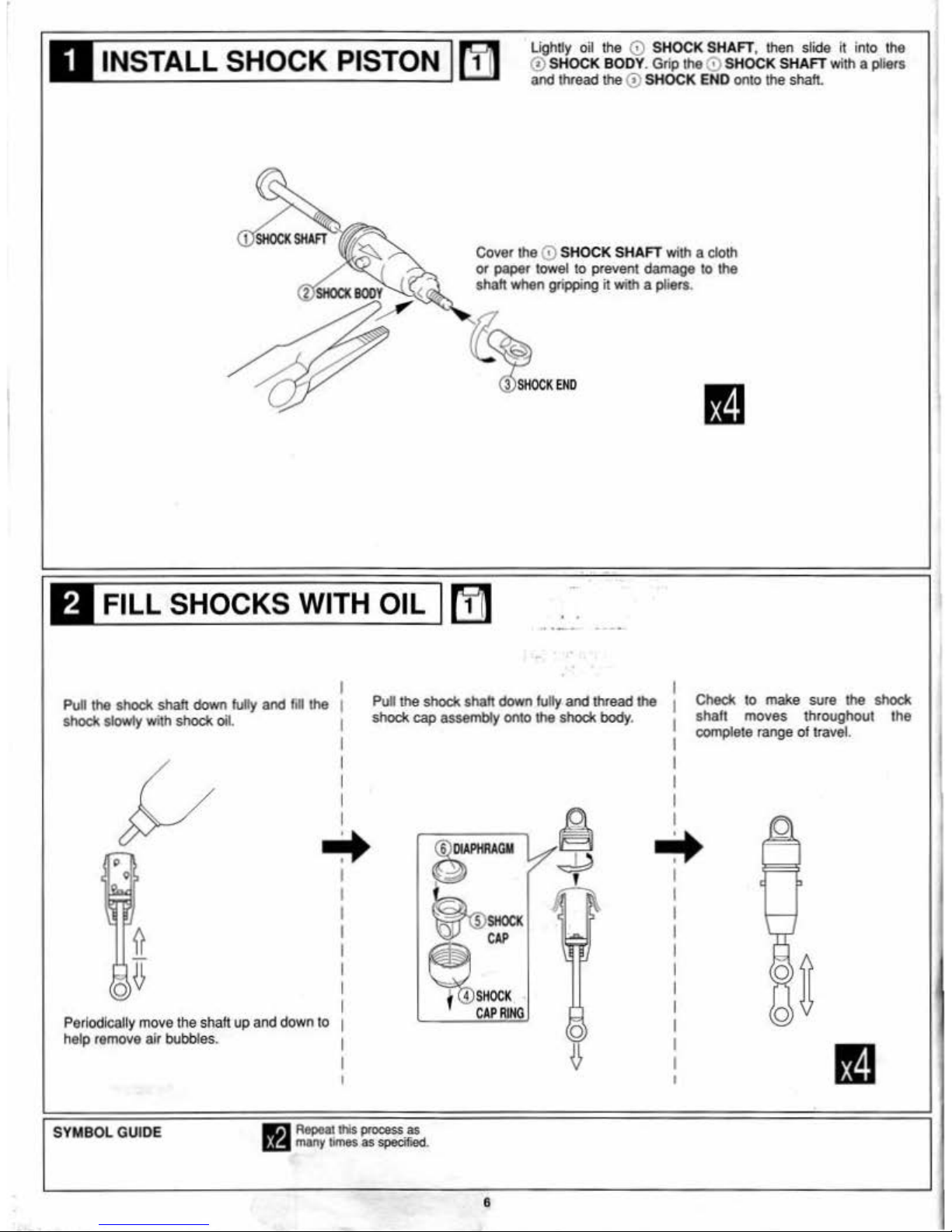
IJINSTALL
SHOCK PISTON I
[!J1
Llghdy oil the 0 SHOCK SHAFT, then slide it into the
<!)SHOCK BODY.
Grip
the0 SHOCK SHAFT with a
pliers
and
thread the
<!)
SHOCK END onto the shalt.
Cover the 0 SHOCK SHAFT with a cloth
or
paper towel to prevent damage to the
shah when gripping
it
with a pliers.
FILL SHOCKS WITH OIL
(!jl
• •
I
Pull the shock
shalt
down
tuly
and
fin
the 1
shock
slowly
with
shock oil. 1
I
I
I
I
I
-
I
Pul
the shock shah down
fully
and
thread the 1
shock cap assembly onto the
shock
body
.
1
I
I
I
I
I
Checl<
to make sure the shock
shaft
moves
throughout the
complete range
of
travel.
...
...
Periodlcall'y move the shah up and down to
help remove air
bubbles.
SYMBOL GUIDE
llil
Ropoatlhls process as
~if!
many
times
as
specified.
0
8
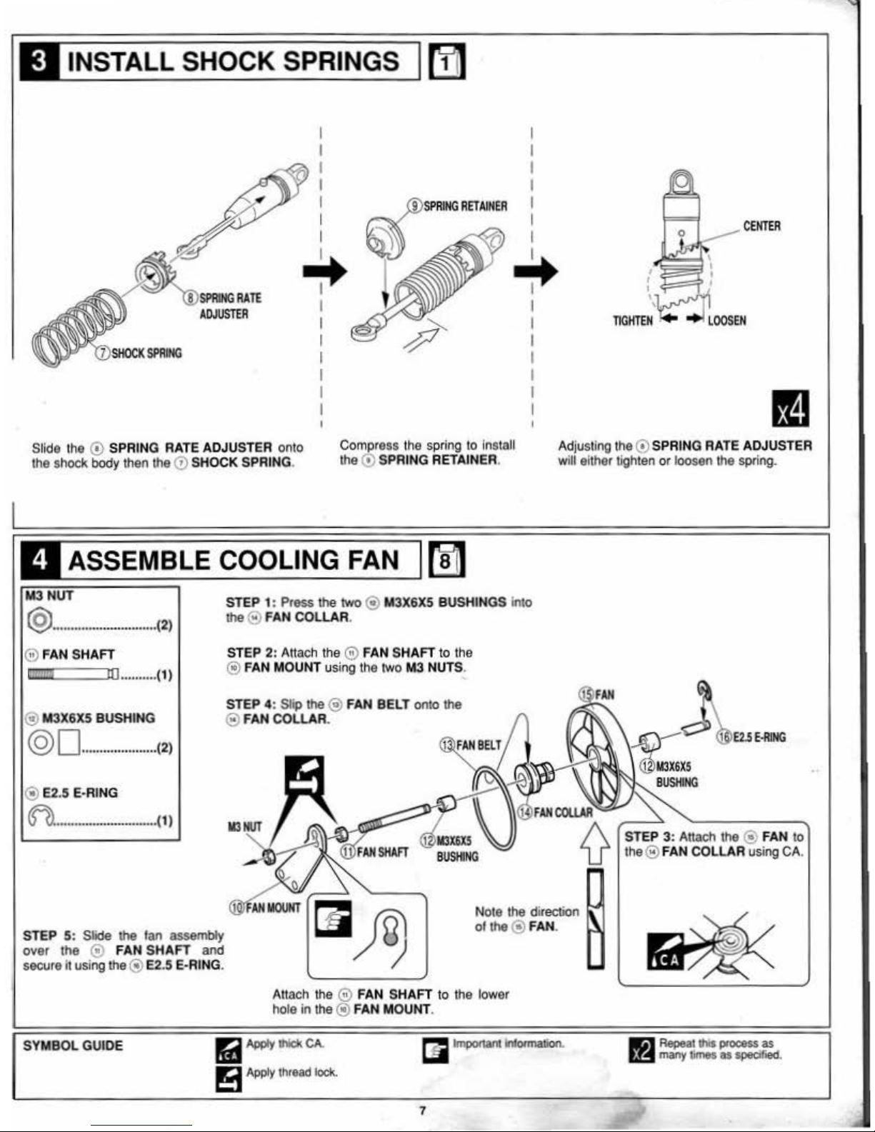
INSTALL SHOCK SPRINGS
[!J1
I I
I
I
I I
I I
I
I
I
I
CENTE.R
I I
~ ~
RATE
I I
ADJUSTER
I
I
I
I
I I
SI'RING
I
I
I I
I I
I I
Slide the
(!)
SPRING RATE ADJUSTER onto
the shock
body
then
lhe
0 SHOCK SPRING.
Compress
the spring
lo
Install
the
(!)
SPRING RETAINER.
Adjusting t
he
(!)
SPRING RATE ADJUSTER
will
e~her
tighten or loosen the spring.
ASSEMBLE COOLING FAN M
@
..............
..........
........
(2)
@ FAN SHAFT
c '
ru
..........
(1l
@ M3X6X5 BUSHING
@0
.....................
(2)
@ E2.5 E·RING
~o
ooooonoouoooo•ooooo.o.,ooo(
1 )
STEP 5: Slide lhe tan assembly
over
the
@ FAN
SHAFT
and
secure it using
lhe
® E2.5 E-RING.
STEP
1: Press
lhe
two
@ M3X6X5 BUSHINGS Into
lhe@ FAN COLLAR.
STEP
2: Altach the 0 FAN SHAFT to the
@ FAN MOUNT using the two
M3
NUTS.
STEP 4: Slip lhe@ FAN BELT onto lhe
@ FAN COLLAR.
Note the direction
ollhe
@ FAN.
Attach the 0 FAN SHAFT
to
lhe low
er
hole
In
the @ FAN MOUNT.
SYMBOL GUIDE
ra
AWY
-
CA.
!':t
Apply
thread
loc
k.
7
STEP 3: Attach
lhe
@ FAN
to
the@ FAN COLLAR using CA.
a
Repeat
lhis
-·as
t,;r:t
many
times
as
specified.
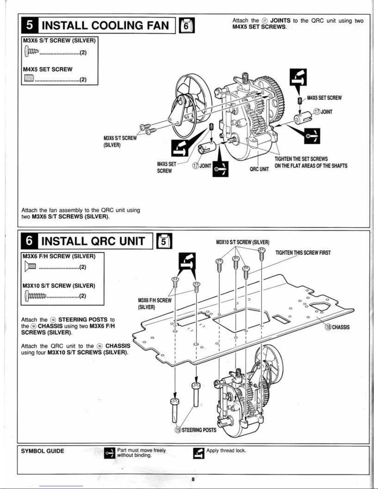
INSTALL COOLING FAN
(!jJ
Attach the
@>
JOINTS
to the QRC unit using two
M4X5
SET SCREWS.
M3X6 SIT SCREW (SILVER)
~
......................... . (2)
M4X5 SET SCREW
lllill1l
.............................
( 2)
Attach the fan assembly
to
the QRC unit using
two M3X6
SIT SCREWS (SILVER).
INSTALL QRC UNIT
rfl1
(::mm'a
..........................
(2)
M3X10 SIT SCREW (SILVER)
p
...
..................
(2)
Attach the @ STEERING POSTS to
the @ CHASSIS using two M3X6 F/H
SCREWS (SILVER).
M3X6 FIH
SCREW
(SILVER)
Attach the QRC unit to the @ CHASSIS
using four M3X10 SIT SCREWS (SILVER).
SYMBOL
GUIDE
Pa
rt
must move
fre
ety
w
ithout
binding
.
TIGIITEII
TilE
SET
SCREWS
ON
TilE
FLAT
AREAS
Of
THE
SHAFTS
1!!3
Appl
y lhread l
ock.
8
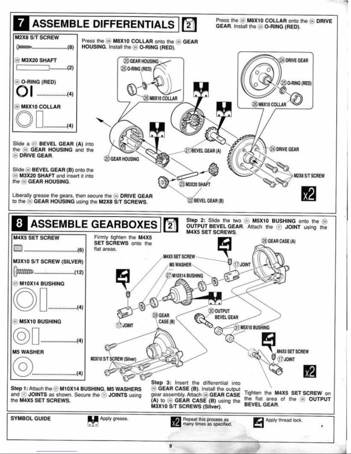
ASSEMBLE DIFFERENTIALS
~
Press the @
M8X1
0 COLLAR onro the @ DRIVE
GEAR. Install the@ D-RING (RED).
0
ffilf!!!!·
..........................
. (8)
@ M3X20 SHAFT
............. (2)
@)
D-RING (RED)
0 I
.....................
(4)
@ M8X10 COLLAR
0 0
................
(
4)
Press the @ M8X10 COLLAR onto the @ GEAR
HOUSING. lnslall the@ ().RING (RED).
Slide a @ BEVEL GEAR (A) into
the
@ GEAR HOUSING and the
@ DRIVE
GEAR.
Slide@ BEVEL GEAR (B) onto the
® M3X20 SHAFT and insert it into
the @ GEAR HOUSING.
Ube
ra
lly grease
the
gears. then secure
the® DRJVE
GEAR
to
th
e@ GEAR HOUSING using the M2X8
SfT
SCREWS.
ASSEMBLE GEARBOXES M
Step 2: Slide the two @ M
5X1
0 BUSHING onto the @
OUTPUT BEVEL GEAR. Attach the @ JOINT using the
M4X5
SET SCREWS.
lilliiil
......
.....
....
0
......................
( 6)
M3X10
SfT
SCREW (SILVER)
~
............................ (12)
@ M10X14 BUSHING
co
0
....................
(4)
@ M5X10 BUSHING
@ 0
.........................
(4)
M5WA
SHER
@
.....................
.
........
(4)
Firmly tighten the M4X5
SET SCREWS onto the
flat areas.
Step
1:Attachthe
@ M10X14 BUSHING,
M5
WASHERS
and® JOINTS
as shown. Secure the ® JOINTS using
the M4X5
SET SCREWS.
Step
3:
Insert the differential into
@ GEAR CASE (B). lnslall the
output
gear assembly. Attach@ GEAR CASE
(A) to
@ GEAR CASE (B) using the
M3X10
SfT
SCREWS (Sliver).
SYMBOL GUIDE
Apply
grease
.
9
Repea
t t
his
proeess
as
many times as
spedfled.
Toghten
the M4X5 SET SCREW
on
the flat area ot the
<!!;
OUTPUT
BEVEL
GEAR.
!3
Apply
thread
lock
.
'
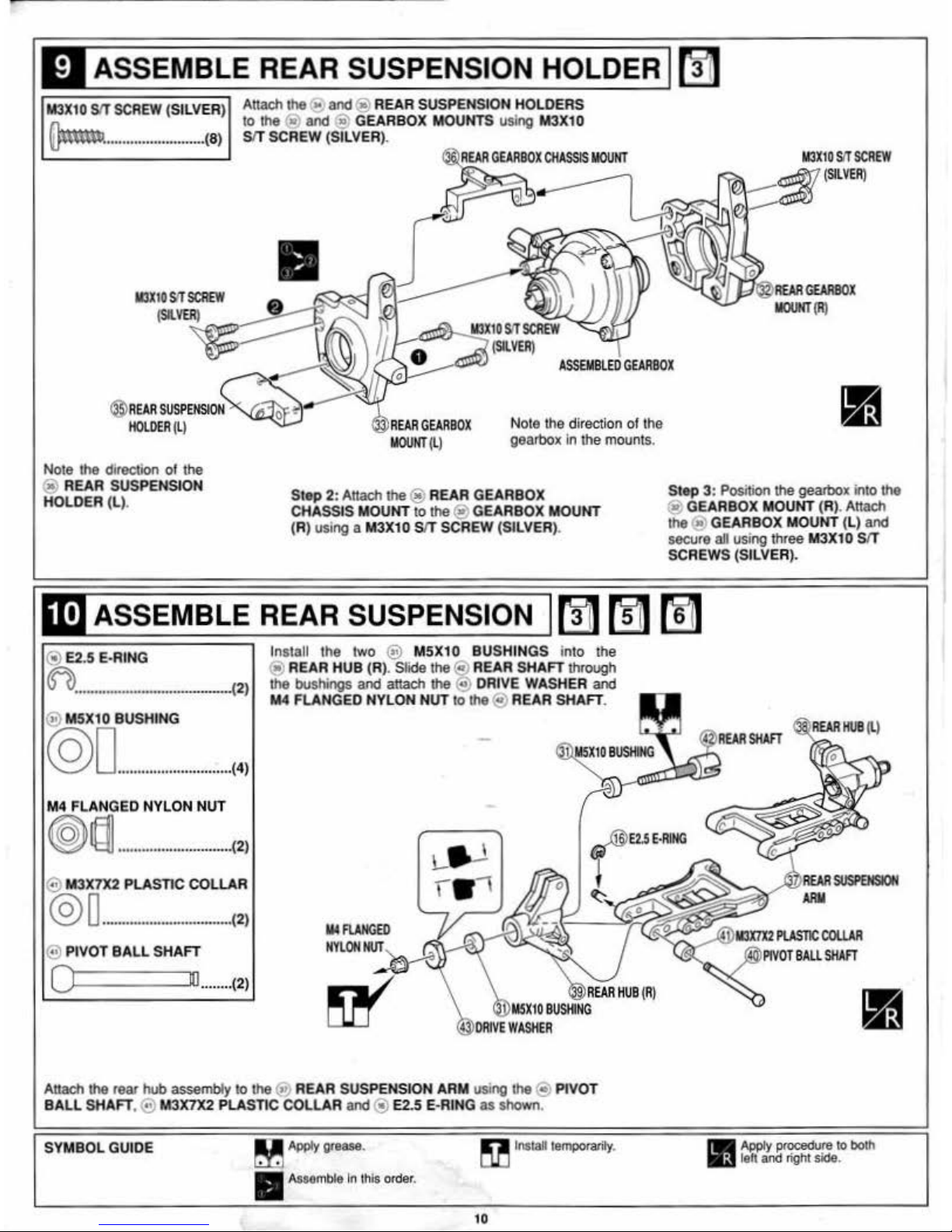
ASSEMBLE REAR SUSPENSION HOLDER
riJ1
M3X10
SIT
SCREW
(SILVER) Attach the " and@ REAR SUSPENSION HOLDERS
(1..-.
lo
lhe
@)
and @ GEARBOX MOUNTS using M3X10
llJ'"'""·
.......................
..
(8
) SIT SCREW (SILVER
).
113X
I D
SIT
SCREW
(SILVER)
II
•
113X
tD
SIT
SCREW
~(
SILVER
)
REAli
GEARBOX
IIOUHT
(R)
ASSEMBLED
GEARBOX
Nole lhe direction
of
the
® REAR SUSPENSION
HOLDER
(L).
Nole l
he
direction of
lhe
gearbox In lhe
mounls.
St
ep
2:
AHach
the® REAR GEARBOX
CHASSIS MOUNT
lo
lhe
® GEARBOX MOUNT
(R) using a M3X10 SIT SCREW (SILVER).
St
ep
3:
Position
lhe
gearbox into lhe
@ GEARBOX MOUNT (R). Attach
lhe
@1
GEARBOX MOUNT (L)
and
secure all using three M3X10 SIT
SCREWS (SILVER).
ASSEMBLE REAR SUSPENSION M
r!jJ
M
@ E2.5 E·RING
~
..........................................
.....
(2)
@ M
SX10
BUSHING
©0
..............
...............
(4)
M4 FLANGED NYLON NUT
@
1§1
.................
....
........
. (2)
@ M3X7X2 PLASTIC COLLAR
@ 0
....................
.
............
(2)
@ PIVOT
BALL
SHAFT
0
111
........ (2)
lnslall
lhe
two @ MSX10 BUSHINGS
inlo the
10)
RE.AR HUB (R). Slide the@ REAR
SHAFT
lhrough
lhe
bushings
and attach lhe @ DRIVE WASHER and
M4
FLANGED NYLON NUT
to
lhe
@ REAR
SHAFT
.
~
15XtD
BUSHING
Attach the rear hub assembly
lo
the@ REAR SUSPENSION ARM using the @ PIVOT
BA
LL SHAFT,@ M3X7X2 PLASTIC COLLAR
and
@ E2.5 E·RING
as
shown
.
SYM
BOL
GUIDE
M
AW:t
gtease.
~
Install
temporarily
.
A
sMmble
In this ord
er.
10
Apply
procedure
to
both
left
and
right side.
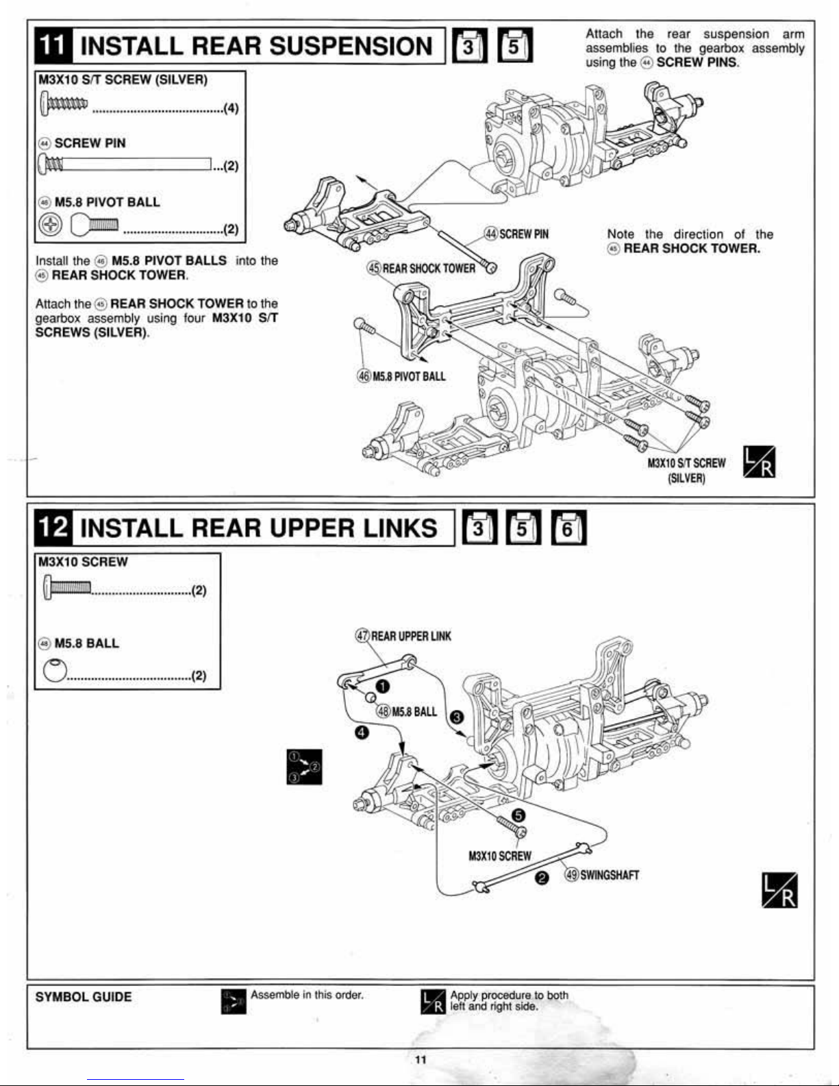
M3X10 SIT SCREW (SILVER)
~
........................................ (4)
@ SCREW PIN
{)mi$iic=c=c=c=
::::JI
...
(2)
@ M5.8 PIVOT
BALL
~
()mm
.............................
(2)
Install the @ M5.8 PIVOT BALLS into the
@)
REAR SHOCK TOWER.
Attach the@ REAR SHOCK TOWER
lo
the
gearbox assembly using four
M3X1 0 SIT
SCREWS (SILVER).
Attach t
he
rear
suspe nsion arm
assembli
es
to the gearbox assembly
using
the@ SCREW PINS.
Note the direction of the
@)
REAR SHOCK TOWER.
M3X10SJTSCREW
•
(SILVER(
lt11NSTALL REAR UPPER LINKS I M
[fll
M
@MS.8
BALL
0
....................................
(2)
SYMBOL GUIDE
@
llEAII
UPPER
UHK
11
Assemble
in
this
order
.
11
M3X10SCREW
Apply
proced
ure
to both
leh
and right
side.
 Loading...