

Kyosho D2 AMG MERCEDES CLK User Manual
※ご使用前にこの説明書を良くお読みになり十分に理解してください。
Before commencing assembly, please read these instructions thoroughly!
R
THE FINEST RADIO CONTROL MODELS
Size
GP 4WD
組立/取扱説明書
INSTRUCTION MANUAL
Radio Controlled .15 Engine Powered Touring Car Series
SuperTen GP FW-04 4WD
D2 AMG Mercedes CLK
D2AMGメルセデスCLK
目 次 INDEX
●キットの他にそろえる物 REQUIRED FOR OPERATION
●プロポの準備RADIO PREPARATION
●組立て前の注意 BEFORE YOU BEGIN
●ランナー付プラパーツ配置図 ARRANGEMENT OF PLASTIC PARTS ON RUNNERS
●本体の組立て ASSEMBLY
●セッティングガイド ADJUSTMENT
●取扱いの注意 OPERATING YOUR MODEL SAFELY
●スペアパーツ・オプションパーツリスト SPARE PARTS & OPTIONAL PARTS
●分解図 EXPLODED VIEW
2 〜 3
3
4 〜 5
5 〜 6
7 〜 26
27
28
29 〜 31
32 〜 33
安全のための注意事項 SAFETY PRECAUTIONS
この無線操縦模型は玩具ではありません!
●この商品は高い性能を発揮するように設計されています。
組立てに不慣れな方は、模型を良く知っている人にアド
バイスを受け確実に組立ててください。
●小さい部品があるので、組立て作業は、幼児の手がとど
かない所で必ず行ってください。
●動かして楽しむ場所は万一の事故を考えて、安全を確認
してから責任をもってお楽しみください。
●組立てた後も、説明書がいつでも見られるように大切に
保管してください。
※製品改良のため、予告なく仕様を変更する場合があります。 SPECIFICATIONS ARE SUBJECT TO CHANGE WITHOUT NOTICE.
© 2000 KYOSHO/禁無断転載複製
This radio control model is not a toy.
●First-time builders should seek the advice of experienced modellers
before commencing assembly and if they do not fully understand
any part of the construction.
●Assemble this kit only in places out of children's reach!
●Take care before operating this model.
You are responsible for this model's assembly and safe operation!
●Always keep this instruction manual ready at hand for quick
reference, even after completing the assembly.
No. 31001
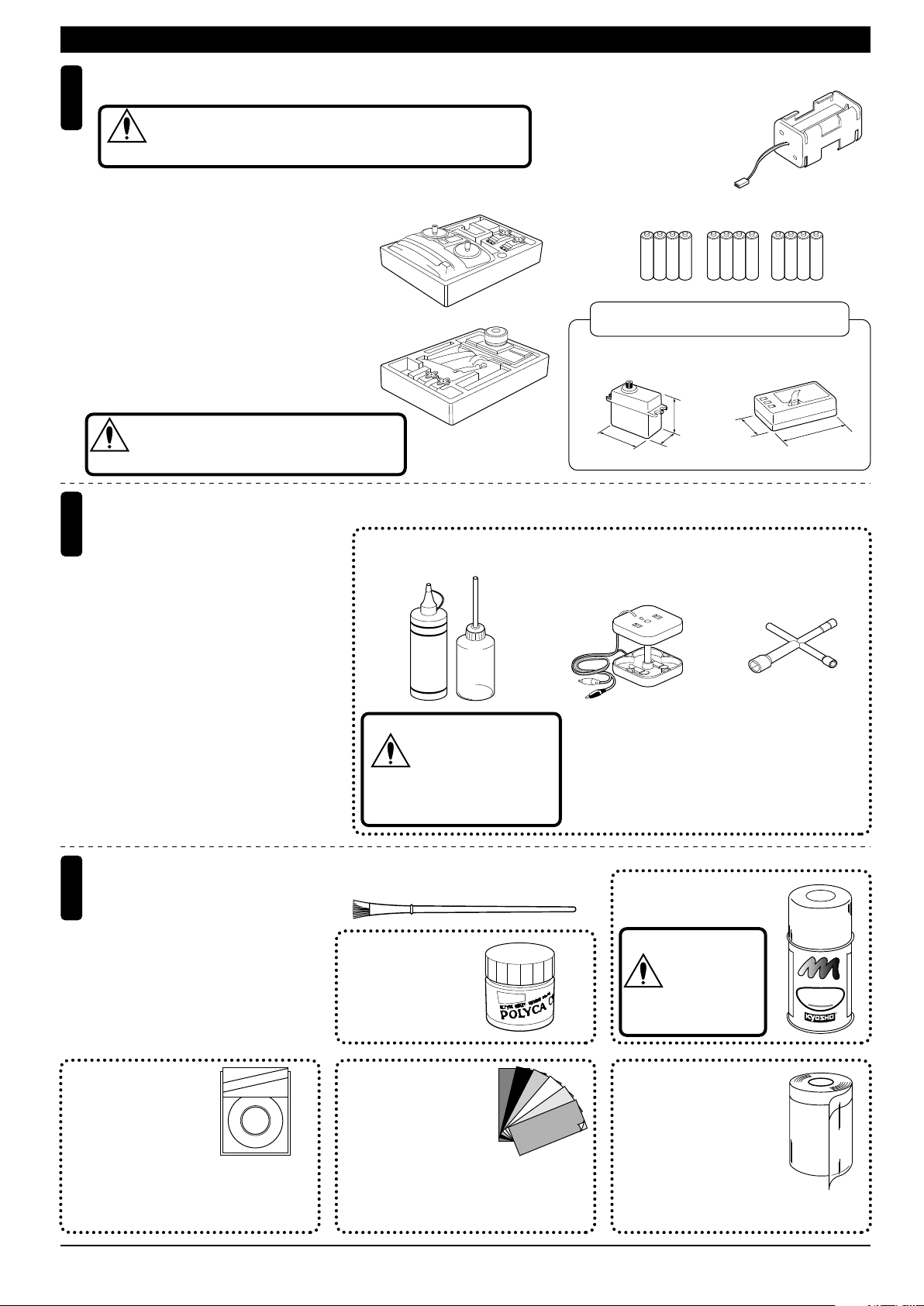
REQUIRED FOR OPERATION (1)キットの他にそろえる物(1)
2チャンネル2サーボ無線操縦機(プロポ)と電池ボックス
Minimum 2 channel radio with 2 servos, and battery box.
1
地上用(自動車用)のプロポ(2チャンネル2サーボ仕様)セットを
必ず使用してください。(地上用以外使用禁止)
CAUTION: Only use a surface radio with 2 channels and 2 servos!
注意
●送信機にはスティックタイプとハン
ドルタイプがありますが、お好みの
タイプを用意してください。
●ステアリングサーボ、スロットルサ
■スティックタイプ
Stick-type
2ch radio.
ーボ共にリバースで使用します。
●プロポの取扱いは、プロポに付属の
説明書を参考にしてください。
●Because there are stick-type and
wheel-type transmitters, use which
ever fits your convenience best.
●Switch the reverse (transmitter) for
■ハンドルタイプ
Wheel-type
2ch radio.
the steer-ing and throttle control.
●For more information on the radio,
refer to its instruction manual.
このサイズのサーボでも一部取付出来ないものもあります。
アッパーデッキを加工して取付けてください。
CAUTION: If servos are not able to install, eaven
注意
this size. Need to modify upper deck.
燃料と始動用具
2
Required for engine starting:
●模型用エンジンは専用のグロー燃料が必
要です。ガソリンや灯油は使用できませ
んので注意してください。また、グロー
燃料は揮発性が高く引火しやすいので取
扱いには充分注意してください。
●エンジン始動にはその他に、プラグを赤
熱させるプラグヒーター(ブースターコ
ード+乾電池)、プラグを脱着するプラ
グレンチが必要です。
●Engines for R/C models require glow fuel.
Be careful not to purchase gasoline or
kerosene by mistake; both cannot be
used! Also, be very careful when han-dling glow fuel which is hi-ghly inflamma-ble and high-explosive!
●Besides glow fuel, engines also require
engine starting equipment. This comprises a glow plug heater (booster cord &
batteries) and a plug wrench for removing and installing the glow plug.
■グロー燃料、燃料ポンプ
Glow Fuel & Fuel Pump
警告
HANDY
FUEL
ガソリンや灯油は
使用禁止
WARNING: Gasoline
or kerosene cannot
be used.
■電池ボックス
Battery Box
●プロポセットに付いていると
きは必要ありません。
If already included with the
radio, no battery box needs
to be pur-chased separately.
■単3乾電池
AA-size Batteries
AAAA
AAAA AAAA
使用できるサーボ・受信機サイズ
Suitable servos & receiver
■サーボ
Servo
31〜36mm
31〜41mm
■ブースターコード
Booster Cord
●エンジン始動に必要な用具(上記3点)を
セットにしました。
No.73301 スターターパック
16〜20mm
■受信機
Receiver
〜32mm
〜48mm
■プラグレンチ
Plug Wrench
塗料と筆
3
Paint and Brush
●ボディの塗装には塗料が必要です。
京商ではモデル用塗料 、スプレーを
用意していますのでご利用ください。
●For painting the body, use Kyosho
paints for models!
No.1841
1842
1843
1859
1860
(1mm x 5m)
(1.5mm x 5m)
(2.5mm x 5m)
(0.4mm x 8m)
(0.7mm x 8m)
Micr
Lin
on
KYOSHO
e Tap
e
ミクロンラインテープ
MICRON LINE TAPE
マスキング、細部デザイン用伸縮自在テープです。
Super-flexible tape for masking and detail designing
jobs.
2
■筆
PAINT BRUSH
No.2230
ポリカカラー
POLYCA COLOR
No.96701〜96703
D-フレックスカラーデカール
D FLEX COLOR DECAL
伸縮自在の特殊素材で3次曲面
にもきれいに貼れる粘着シートです。
Self-adhesive super-flexible sheets that
bond to polycarbonate - even when
applied to curved surfaces.
No.76301〜76711
京商スプレーカラー
KYOSHO SPRAY COLOR
スプレーカラーを
使用する場合、缶
の説明を良く読ん
注意
でください。
CAUTION: Before
using spray colors,
always read their
explanations!
F
U
E
L
P
R
O
F
F
P
K
Y
H
S
O
S
P
R
A
O
Y
C
No.1947
マスキングカバーシート
MASKING SHEET
マスキングテープとビニール
シートが一体になった広範囲
マスク用テープです。
For safe masking jobs, use this plastic masking
sheet featuring one self-adhesive edge.
T
N
I
A
O
R
O
L
R
REQUIRED FOR OPERATION (2)キットの他にそろえる物(2)
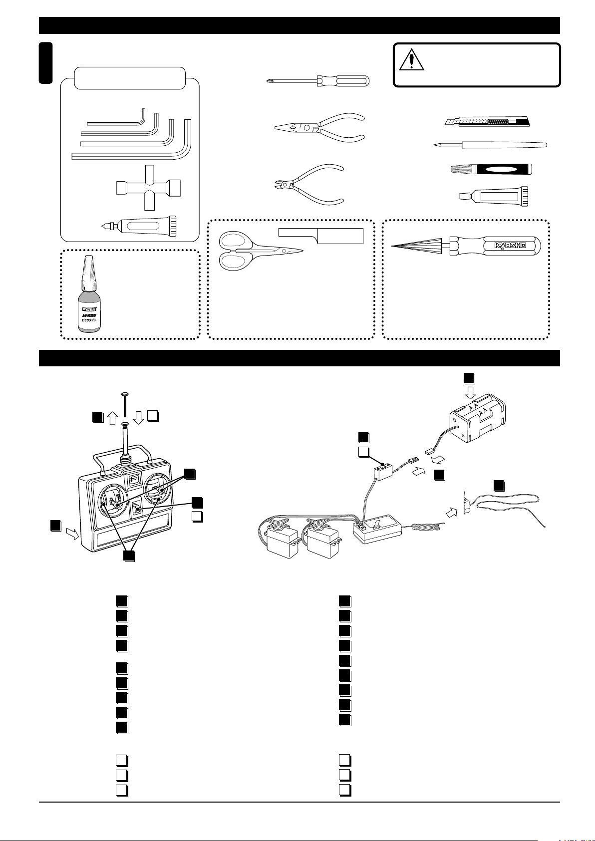
組立てに必要な工具
Tools required
4
キットに入っている工具
TOOLS INCLUDED
■六角レンチ(1.5mm,2mm,2.5mm,5mm)
Hex Wrench (1.5mm, 2mm, 2.5mm, 5mm)
■十字レンチ
Cross Wrench
■グリス
Grease
GREASE
ロックタイト 中強度
LOCTITE
Midium Strength
ビスの緩みを防ぎます。
To prevent the screws
from becoming loose.
No.94402
■+ドライバー(大、中、小)
Phillips Screw Driver (L.M.S)
■ラジオペンチ
Needle Nose Pliers
■ニッパー
Wire Cutters
ラウンドカッター&サンダー
ROUND CUTTER & SANDER
ボディのカット、仕上げ用。曲線部分も楽に
作業ができます。
For trimming bodies. Cutting along curved
lines never was so easy!
No.1829
使用する工具の取扱いには、充分
注意してください。
CAUTION: Handle tools carefully!
注意
■カッターナイフ
Sharp Hobby Knife
■キリ
Awl
■瞬間接着剤
Instant Glue
■ゴム系接着剤
Rubber Cement
スペシャルテーパーリーマー
SPECIAL TAPER REAMER
下穴加工が不要で、直接1mm〜15mmの正確な
穴あけができる工具です。
No need to pre-drill!
Drills neat 1mm to 15mm holes directly!
ゴム系接着剤
No.80311
プロポの準備 RADIO PREPARATION
●プロポを下の順序にしたがってセットします。
Set up the radio control system as indicated below.
2
12
10
ON
8
OFF
9
▲スイッチ
ON
7
11
OFF
1
▲送信機
6
Transmitter
Switch
▲受信機
Receiver
▲サーボ
Servo
●始める時
1
単3乾電池をセットする。(送信機)
アンテナをのばす。(送信機)
2
単3乾電池をセットする。(電池ボックス)
3
単3乾電池をセットした電池ボックスの
4
コネクターをつなぐ。
アンテナをのばす。(受信機)
5
トリムを中央にセットする。
6
スイッチを入れる。(送信機)
7
スイッチを入れる。(受信機)
8
スティックを動かしてサーボが動いているか確認。
9
●START
1
Insert AA-size dry batteries. (Transmitter)
Extend the antenna. (Transmitter)
2
Insert AA-size dry batteries. (Battery Box)
3
Connect the battery box.
4
Extend the antenna. (Receiver)
5
Center the trims.
6
Switch on the transmitter.
7
Switch on the receiver.
8
Make sure the servos move according to
9
your transmitter inputs.
3
4
5
●終わる時
スイッチを切る。(受信機)
10
スイッチを切る。(送信機)
11
アンテナを縮める。(送信機)
12
●FINISH
Switch off the receiver.
10
Switch off the transmitter.
11
Retract the antenna. (Transmitter)
12
3
組立て前の注意(1) BEFORE YOU BEGIN (1)
組立てる前に説明書を良く読んで、おおよその構造を理解してから組立てに入ってください。
1
Read through the manual before you begin, so you will have an overall idea of what to do.
キットの内容をお確かめください。万一不良、不足がありましたら、お買い求めの販売店にご相談いただくか、当社「ユーザー相談室」までご連絡ください。
2
Check all parts. If you find any defective or missing parts, contact your local dealer or our Kyosho Distributor.
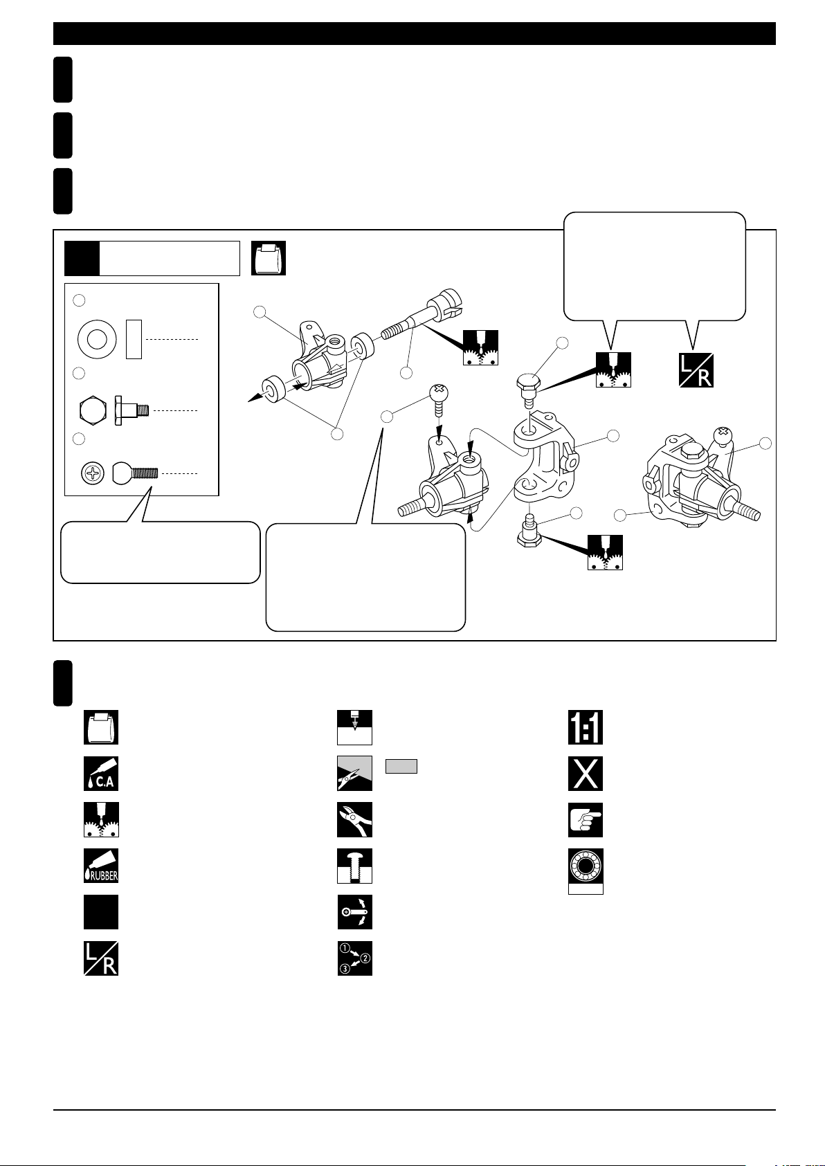
説明書の見かた
3
How to read the instruction manual:
〔説明例Example〕
説明書内では多くのマークが使用
フロントサスペンション
Front Suspension
1
4
5 x 10mm メタル
Metal Bushing
No.4, No.5, No.6
1
されています。マークに注意して
組立てを進めてください。
This instruction manual uses several symbols. Please note them
during the entire assembly.
4
キングピン
5
King Pin
4
5.8mm ピロボール(黒)
6
Pillow Ball (Black)
2
小物部品の名前、原寸図、使用数。
Key Number, Part Name, True-to-scale
Diagram, Quantity Used
説明書に使われているマーク
4
Symbols used throughout the instruction manual, comprise:
使用する袋詰。
Part bags used.
キット内の部品は、ビス類を除いてキー
No.が付けられています。スペアパーツを
購入する時はキーNo.を参照して下さい。
All parts except screws are identified by
key numbers. For purchasing spare parts,
find the key no. of the part needed in the
spare part list and refer to the left column
to look up the corresponding order no.
4
2mm
3
6
2mmの穴をあける(例)。
Drill holes with the specified
diameter (here: 2mm).
5
7
R
L
5
8
原寸図
True-to-scale diagram.
2
x
瞬間接着剤で接着する。
Apply instant glue (CA glue, super glue).
グリスを塗る。
Apply grease.
ゴム系接着剤で接着する。
Apply rubber cement.
2セット組立てる(例)。
Assemble as many times as
2
specified (here: twice).
左右同じように組立てる。
Assemble left and right sides
the same way.
をカットする。
Cut off shaded portion.
余分をカットする。
Cut off excess.
仮止め。
Tentatively tighten.
可動するように組立てる。
Ensure smooth non-binding
movement while assembling.
番号の順に組立てる。
Assemble in the specified
order.
1901
別購入品
Must be purchased separately!
注意して組立てる所。
Pay close attention here!
オプションのベアリングの品番。
例:No.1901
Ball bearings are optional!
(with optional part no.)
4
組立て前の注意(2) BEFORE YOU BEGIN (2)
キットには、形や長さが違うビスや小物部品が多く入っています。説明書には原寸図がありますので確認してから組立ててください。
5
また、ビス類は多めに入っているものもありますので、予備としてお使いください。
This kit contains screws and hardware in different metric sizes and shapes.
Before using them, check the screws on the true-to-scale diagrams on the left side in each assembly step. Some screws are extras.
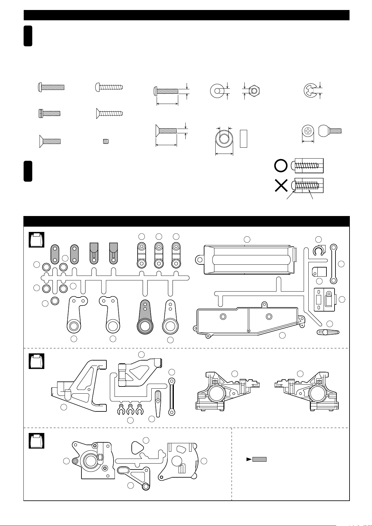
●ビスの種類 SCREWS
ビス Screw
キャップビス
Cap Screw
サラビス
Flat Head (F/H) Screw
TPビスは、部品にネジを切りながらしめつけるビスです。しめこみが固い場合がありますが、
6
部品が確実に固定されるまでしめこんでください。ただし、しめすぎるとネジがきかなくなり
ますので、部品が変形するまでしめないでください。
Self-tapping (TP) screws cut threads into the parts when being tightened. Excessive force may
permanently damage parts when tightening TP screws. It is recommended to stop tightening when
the part is attached or when some resistance is felt after the threaded portion enters the plastic.
TPビス
Self-tapping (TP) Screw
TPサラビス
TP F/H Screw
セットビス
Set Screw
●小物部品のサイズ例 OTHER HARDWARE
3x12mmビス
Screw
12mm
3x12mmサラビス
F/H Screw
3mm
12mm
3mmワッシャー・ナット
Washer・Nut
3mm
5x10mmメタル・ベアリング
Metal Bushing・Bearing
5mm
10mm
ランナー付プラパーツ配置図 ARRANGEMENT OF PLASTIC PARTS ON RUNNERS
100
No.1
13
13
101102
SFH
3mm
110
Correct
Wrong
しめすぎ
Overtightened.
E3Eリング
E-ring
3mm
6.8mmピロボール
Pillow Ball
6.8mm
ビスがきかない
The threads are stripped.
107
144
13
14
No.3
No.4
13
1
2
3
39
84
40
142
143
98
51 52
111
108
106
109
37 38
部分の部品は、使用しません。
Shaded Parts are not used.
53
5
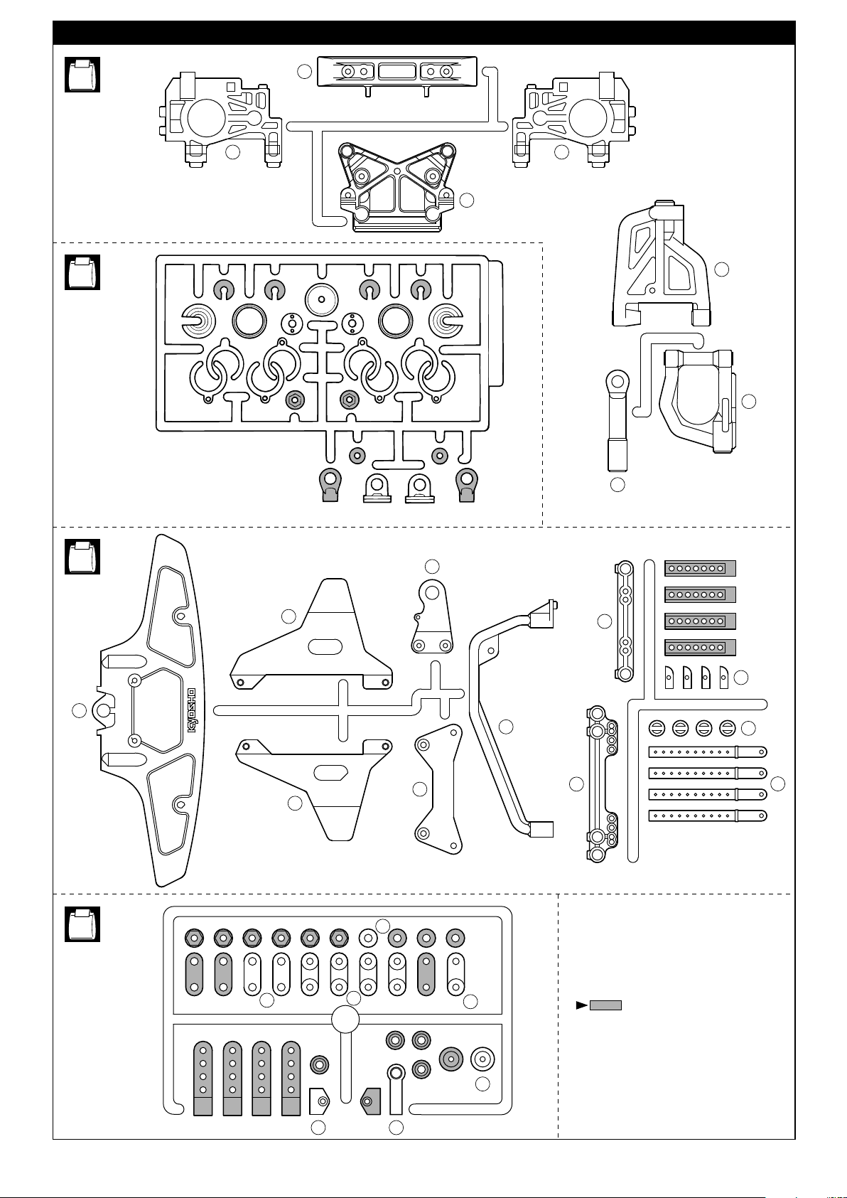
ランナー付プラパーツ配置図 ARRANGEMENT OF PLASTIC PARTS ON RUNNERS
No.5
No.6
G-6
85
71 70
74
G-10
G-6
G-4
G-1 G-1
G-4
G-5G-5
63
62
87
No.7
89
88
G-3 G-3
86
140
113
137
64
136
132
133
135
No.9
104
120
105
121
139
141
部分の部品は、使用しません。
Shaded Parts are not used.
145
6
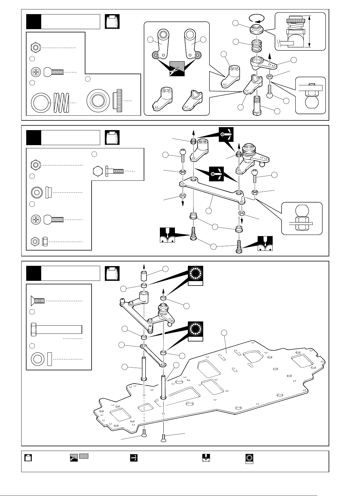
ステアリング
Steering
1
3mm
ナット
Nut
5.8mm
9
5
ピロボール(銀)
Pillow Ball (silver)
サーボセイバースプリング
Servo Saver Spring
1
1
6
セイバーナット
Saver Nut
No.1
1 2
6
24mm
5
1
3
3mm
ステアリング
Steering
2
3mm
ナット
Nut
10
3 x 6mm
Metal Bushing
5.8mm
9
Pillow Ball (silver)
2.6mm
Nylon Nut
メタル
ピロボール(銀)
ナイロンナット
ステアリング
Steering
3
3 x 8mm
F/H Screw
12
サラビス
ユニクランクシャフト
Unicrank Shaft
1
1
2
11
ステアリングピン
Steering Pin
4
2
No.1
2
2.6mm
3mm
3mm
9
2.6mm
9
4
9
3mm
8
2
3mm
10
2
11
No.1
14
1902
13
2
13
13
5 x 8 x 2.5mm
使用する袋詰。
Part bags used.
2
プラメタル
Plastic Bushing
4
Cut off shaded portion.
3x8mm
144
13
12
movement while assembling.
12
13
1902
3x8mm
15
グリスを塗る。可動するように組立てる。 をカットする。 オプションのベアリングの品番。
Apply grease.Ensure smooth non-binding
Ball bearings are optional !
1901
(with optional part no.)
7
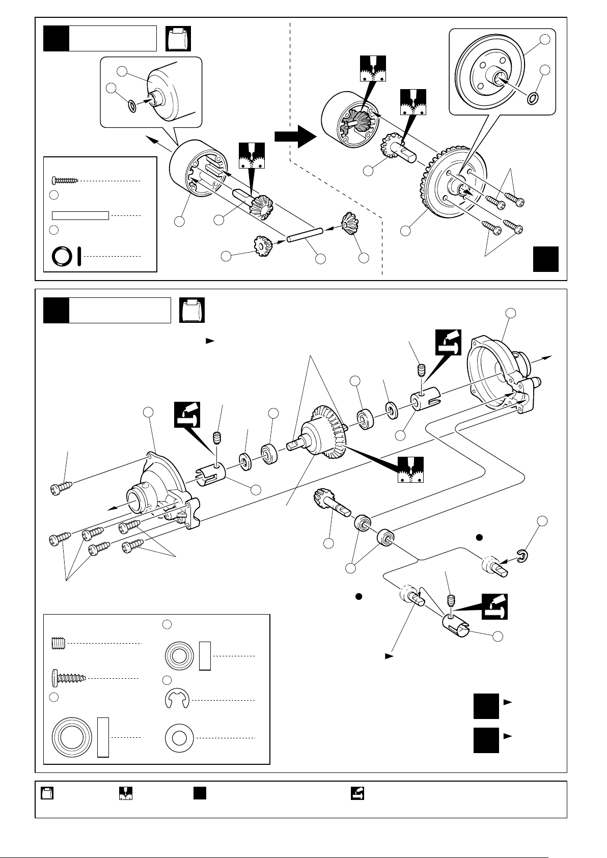
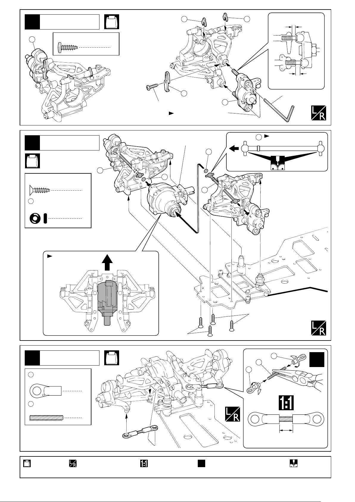
デフギヤ
Gear Differential
4
No.2
20
2 x 8mm
TP Screw
19
21
5
TPビス
3 x 20mm
Shaft
Oリング
O-ring
シャフト
ギヤボックス
Gearbox
21
16
21
2x8mm
2x8mm
24
x
2
8
2
4
16
17
18
19
17
20
18
No.2
平らな面にセットビスを固定する。
Firmly tighten the set screws onto the flat spots.
4x4mm
3x10mm
3x10mm
4 x 4mm
Set Screw
3 x 10mm
TP Screw (Silver)
22
セットビス
TPビス(銀)
8 x 14mm
Ball Bearing
ベアリング
12
25
3x10mm
27
5 x 10mm
Ball Bearing
5
28
E4
E-ring
5mm
Washer
4
4x4mm
ベアリング
Eリング
ワッシャー
5mm
23
デフギヤ
Gear Differential
4
1
4
22
26
22
27
5mm
フロント
Front
23
リヤ
Rear
4x4mm
23
平らな面にセットビスを固定する。
Firmly tighten the set screws onto
the flat spots.
フロント用
1
1
For Front
リヤ用
For Rear
x
x
28
使用する袋詰。
Part bags used.
8
x
2
Assemble as many times as specified.Apply grease.
ネジロック剤を塗る。2セット組立てる(例)。グリスを塗る。
Apply threadlocker (screw cement).
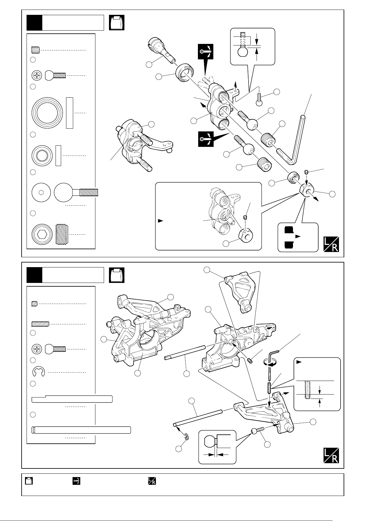
フロントサスペンション
Front Suspension
6
No.3
< Left >
左側用
4 x 4mm
Set Screw
9
32
33
34
35
セットビス
5.8mm
ピロボール(銀)
Pillow Ball (silver)
12 x 18mm
Ball Bearing
6 x 12mm
Ball Bearing
11mm
Pillow Ball
11mm
Pillow Ball Nut
ベアリング
ベアリング
ピロボール
ピロボールナット
2
2
< Right >
2
2
4
4
右側用
Rのマーク
“R” marked
1mm
31
32
六角レンチ(5mm)
Lのマーク
9
“L” marked
Hex Wrench (5mm)
34
30
R
29
35
34
35
4x4mm
33
36
4x4mm
平らな面にセット
ビスを固定する。
Firmly tighten the
set screws onto
the flat spots.
36
内側
Inside
フロントサスペンション
Front Suspension
7
3 x 3mm
Set Screw
3 x 10mm
Set Screw
9
146
41
42
セットビス
セットビス
5.8mm
ピロボール(銀)
Pillow Ball (silver)
E3
Eリング
E-ring
サスシャフト(E)
Suspension Shaft (E)
サスシャフト(D)
Suspension Shaft (D)
No.3
39
< Left >
< Right >
右側用
左側用
39
2
37
2
六角レンチ(2.5mm)
Hex Wrench (2.5mm)
40
2
2
38
41
42
2
3x3mm
3x10mm
車高調整用。
For adjusting the
ride height.
2.5mm
40
2
146
1mm
9
使用する袋詰。
Part bags used.
可動するように組立てる。
Ensure smooth non-binding
movement while assembling.
左右同じように組立てる。
Assemble left and right sides the same way.
9
フロントサスペンション
Front Suspension
8
No.3
142 142
約5mm
approx. 5mm
30
9
3 x 10mm
TP Screw (Silver)
フロントサスペンション
Front Suspension
No.3
3 x 12mm
TP F/H Screw
44
Oリング
O-ring
TPサラビス
TPビス(銀)
2
< Right >
右側用
43
4
< Left >
左側用
3x10mm
フロントギヤボックス
Front Gearbox
44
143
29
交互に少しずつねじ込む。
Tighten this 2 screws reciprocally.
内側
Inside
44
43
向きに注意。
43
Note the direction.
約5.5mm
approx. 5.5mm
六角レンチ(2.5mm)
Hex Wrench (2.5mm)
ステアリング
Steering
10
45
5.8mm
ボールエンド(L)
Ball End (L)
2
向きに注意。 前
Note the direction. Front
No.3
4
3x12mm
3x12mm
45
46
45
x
2
4623 x 20mm
Set Screw
使用する袋詰。
Part bags used.
10
セットビス
左右同じように組立てる。
Assemble left and right sides
the same way.
原寸図。
True-to-scale diagram.
2セット組立てる(例)。
x
2
Assemble as many times as specified.
約8mm
approx. 8mm
グリスを塗る。
Apply grease.
 Loading...