

Page 1
※ご使用前にこの説明書を良くお読みになり十分に理解してください。
Before beginning assembly, please read these instructions thoroughly.
R
キャリバー30用 FTボデイ
CALIBER30FTBODY
説明書に使われているマークSymbols used throughout the instruction sheet.
2mmの穴をあける(例)。
Drill holes with the specified
2mm
diameter (here: 2mm).
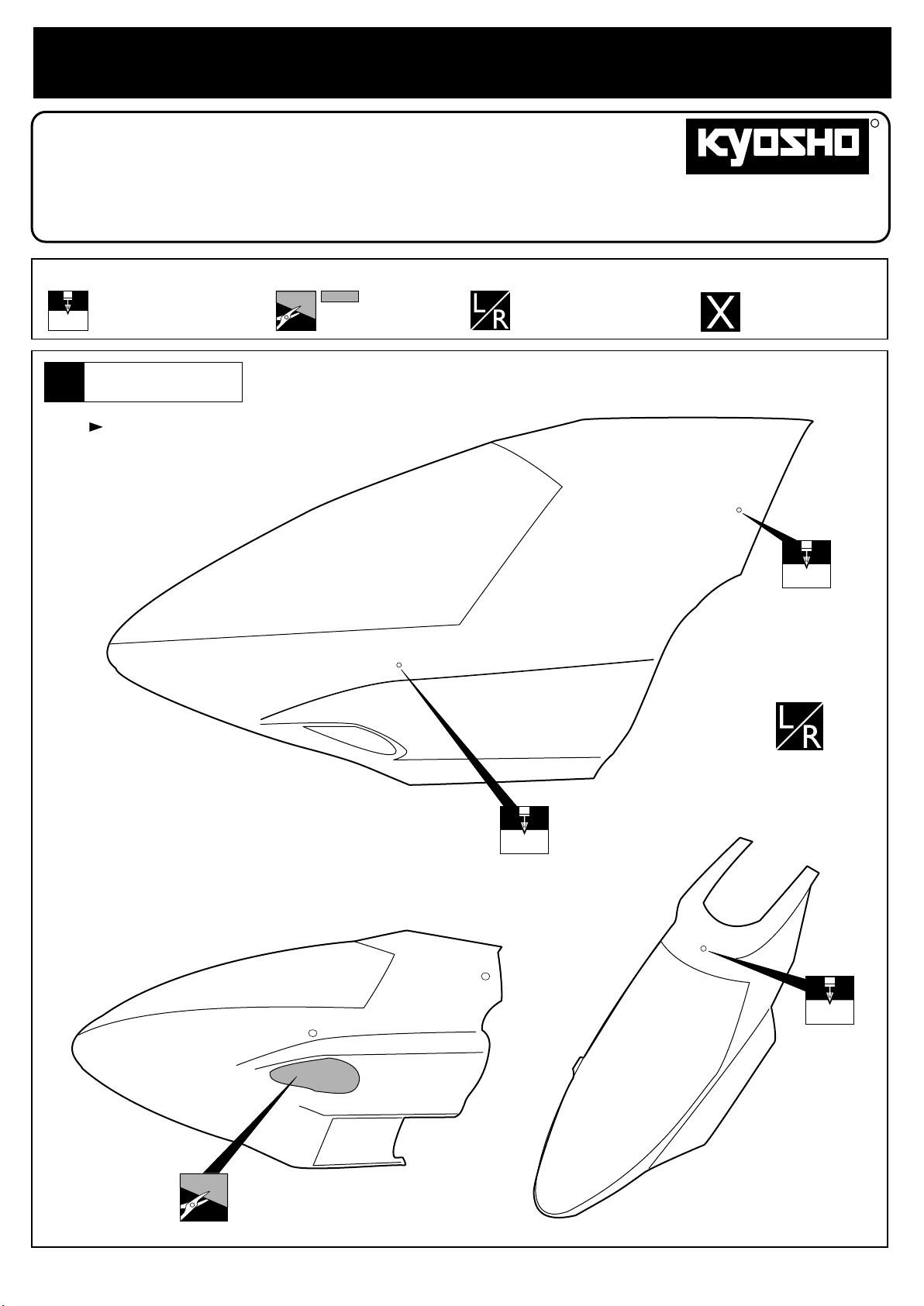
ボディ
Body Shell
1
6.5mmと8mmの穴開け位置にマーク有り。
There are marks for the 6.5mm and 8mm holes.
斜線部をカットする。
Cut off shaded portion.
左右同じように組立てる。
Assemble left and right sides
the same way.
THE FINEST RADIO CONTROL MODELS
取扱説明書
INSTRUCTION SHEET
No.CA3501
別購入品
Must be purchased
separately!
6.5mm
6.5mm
8mm
Page 2
2
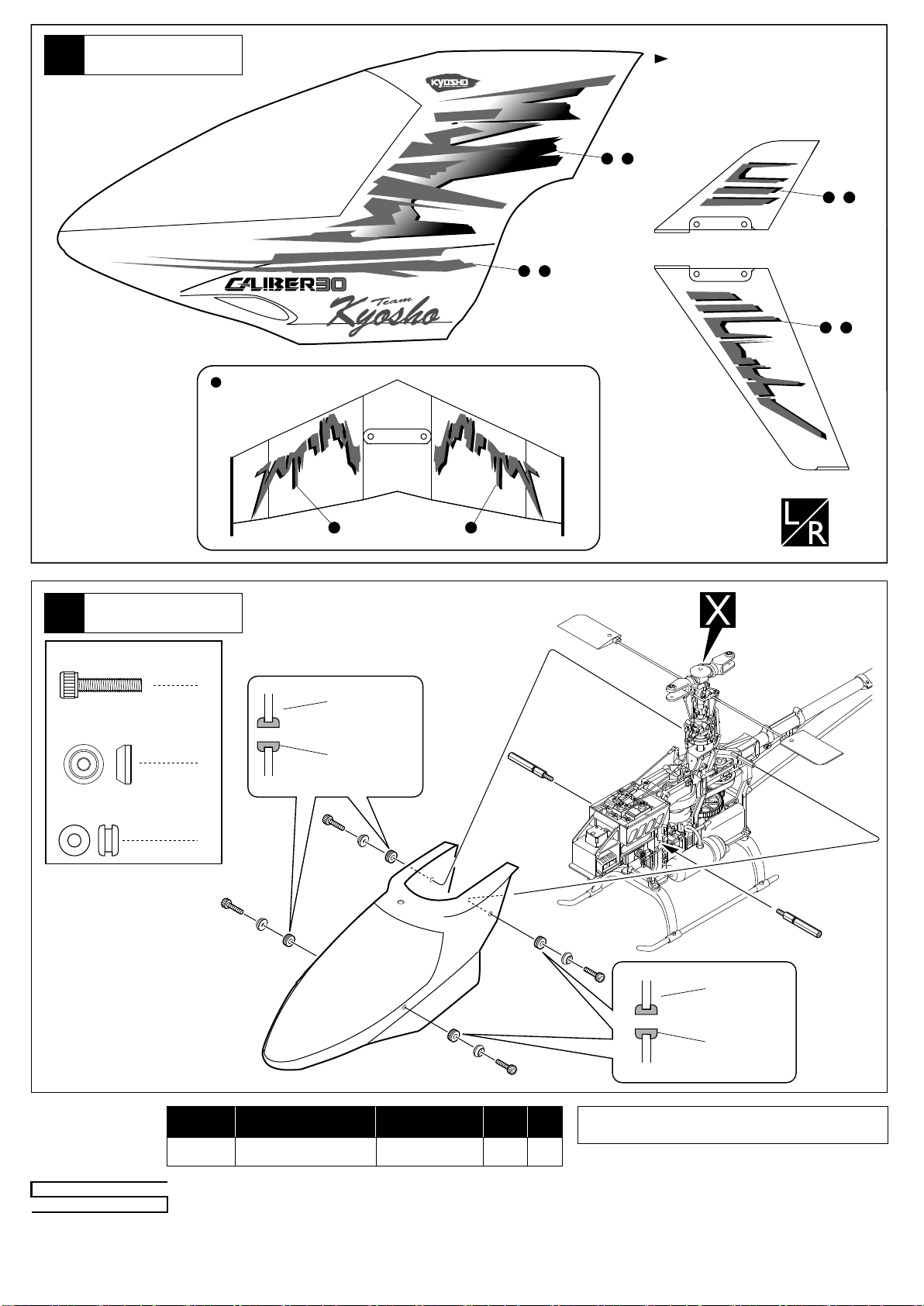
デカール
Decal
上から見た図
Top View
( )
3 4
( )
1 2
カッコの中は反対側用のデカール
ナンバーです。
The decal numbers between brackets
are only for the opposite side.
( )
7 8
( )
5 6
ボデイ
Body Shell
3
3 x 15mm
Cap Screw
ボディーマウントワッシャー
Body Mount Washer
グロメット
Grommet
キャップビス
9
4
10
ボディ
Body Shell
4
4
グロメット
Grommet
スペアパーツ
SPARE PARTS
メーカー指定の純正部品を使用して
安全にR/Cを楽しみましょう。
※製品改良のため、予告なく仕様を変更する場合があります。
*SPECIFICATIONS ARE SUBJECT TO BE CHANGED WITHOUT NOTICE.
© 2002 KYOSHO CORPORATION/禁無断転載複製
品番
No.
CA3501-01
パーツ名
Part Names
デカール(FTボディ用)
Decal (For FT Body)
Quantity
x 1 set
内容
★定価
2000
ボディ
Body Shell
グロメット
Grommet
★発送
手数料
200
パ−ツの価格 には、消費税 は含まれてお りません。ま た、定価、発 送手
数料、消費税は平成14年 8 月 1 日現在のもので、法規改正、運賃改
定、諸事情などにともない変更になりますのでご了承ください。
京商株式会社
〒243-0034 神奈川県厚木市船子153
お問い合わせは:月曜〜金曜(祝祭日を除く) 10:00〜18:00
●ユ−ザ−相談室直通TEL.046-229-4115
0208 PRINTED IN JAPAN
Page 3
※組立てる前にこの説明書を良くお読みになり十分に理解してください。
Before beginning assembly, please read these instructions thoroughly.
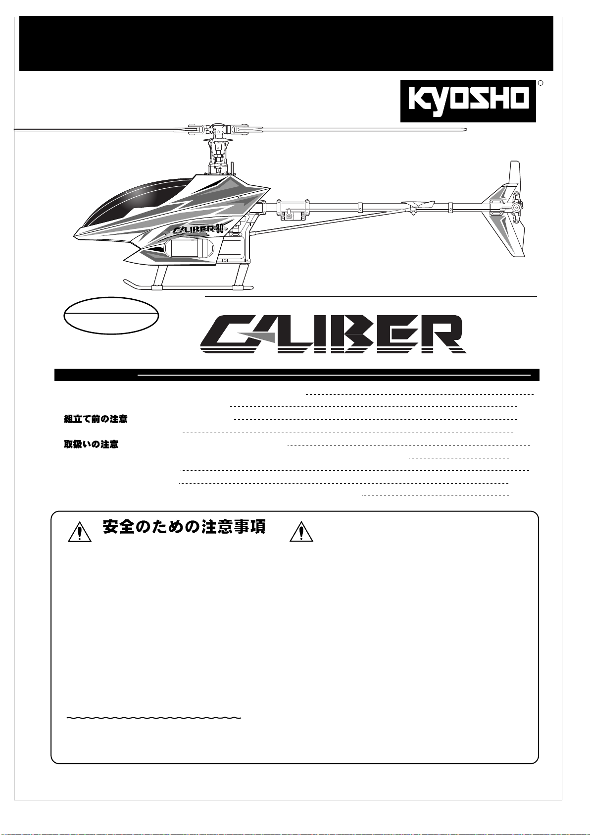
INSTRUCTION MANUAL
R
THE FINEST RADIO CONTROL MODELS
上級者向
For Advanced Flyers
RADIO CONTROLLED ENGINE POWERED HELICOPTER
組立/取扱説明書
目 次 INDEX
●キットの他にそろえる物 REQUIRED FOR OPERATION
●プロポの準備 RADIO PREPARATION
● BEFORE YOU BEGIN
●本体の組立て ASSEMBLY
● OPERATING YOUR MODEL SAFELY
●調整・飛行練習・メンテナンス SETTINGS ¥ FLIGHT LESSONS ¥ MAINTENANCE
●パーツリスト PARTS LIST
●分解図 EXPLODED VIEW
●スペアパーツ・オプションパーツリスト SPARE & OPTIONAL PARTS
UNDER SAFETY PRECAUTIONS
(これはあなたの責任です)
この無線操縦模型は玩具ではありません!
●高速で回転するローターが付いた危険性のある
です。
組立て、飛行(場所、電波)、点検、整備はご自身が
責任をもって行ってください。
●小さい部品が多いので、組立て作業は、必ず幼児の
手がとどかない所で行ってください。
●フライト前、フライト後は必ず、ビスの緩み、各部
品の劣化などを点検し、異常があれば交換・修理・
調整を行い、安全を確認してからご使用ください。
●純正部品以外のパーツを使用しないでください。事
故や不調の原因になるおそれがあります。
また、社外品を使用しての事故や破損等については、
一切責任を負いませんのでご了承ください。
●組立て後に、もう一度説明書を見直してください。
説明書は、いつでも見られるように大切に保管して
ください。
機械
This radio control model is not a toy.
●This is a kind of machine including a rotor which rotates with
high speed and has a possibility to be dangerous. You are
responsible for this model's assembly, safe operation (place
to fly, frequency) check and adjustment of the model.
●Assemble this kit only in places out of children's reach!
●Take enough safety precaution before and after operation.
After every flight, inspect screws and nuts for looseness, and
parts for wear. Any damaged parts should be immediately
replaced, repaired or adjusted for safe operation.
●Use only Kyosho genuine parts for replacement.
Failing to do so will result in accidents or malfunction of the
model. Kyosho do not take responsibilities for the accidents
and crashes if using the parts which are not Kyosho genuine
ones.
●Always keep this instruction manual ready at hand for quick
reference, even after completing the assembly.
30
キャリバー30
2
3 ~ 4
5 ~ 6
7 ~ 18
19
19 ~ 29
30
31 ~ 35
36 ~ 37
※製品改良のため、予告なく仕様を変更する場合があります。 SPECIFICATIONS ARE SUBJECT TO CHANGE WITHOUT NOTICE.
© 2002 KYOSHO CORPORATION/禁無断転載複製
No. 21135/21137
Page 4
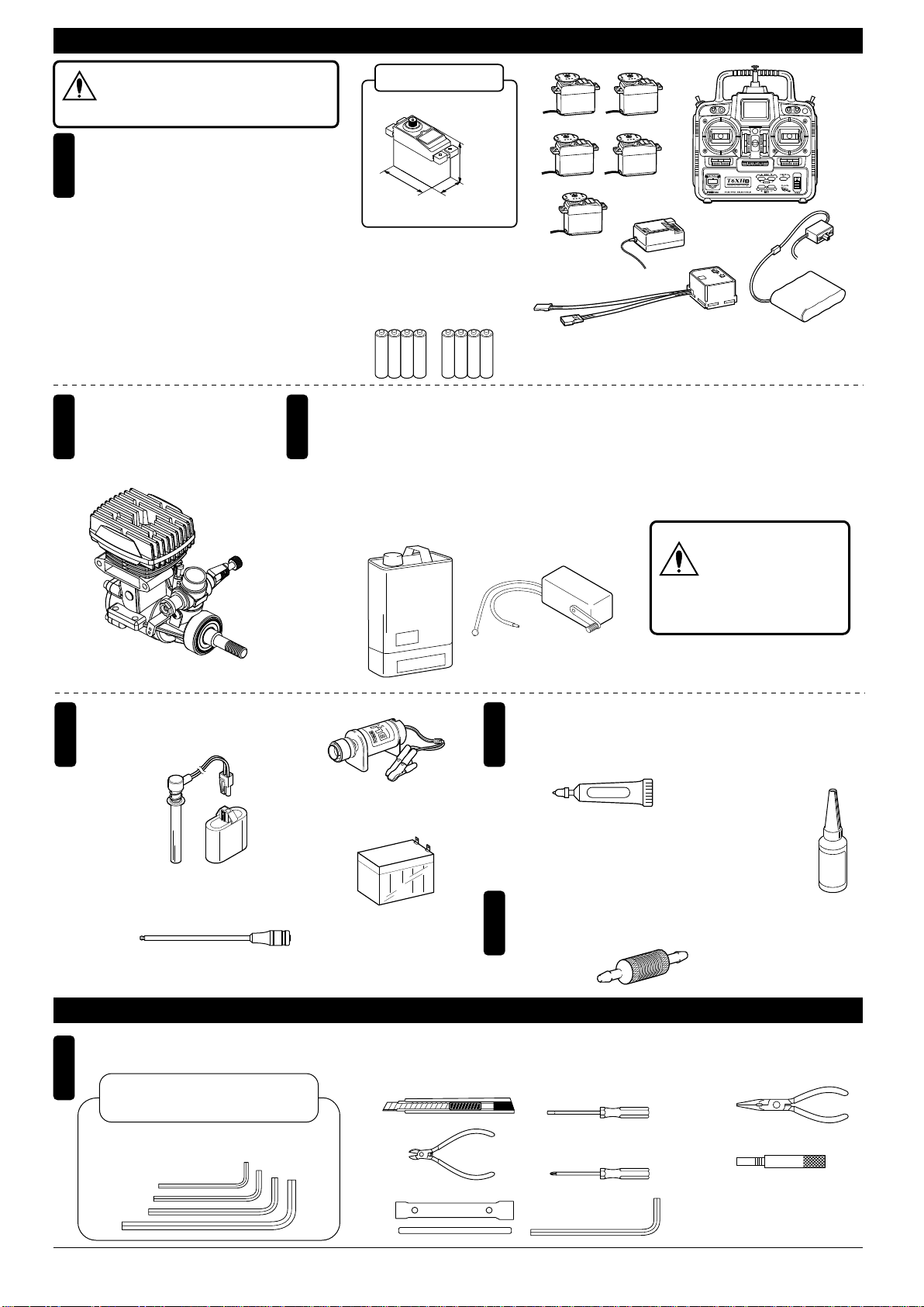
キットの他にそろえる物(1)REQUIRED FOR OPERATION (1)
空用(ヘリ用)のプロポセットを必ず
使用してください。(空用以外使用禁止)
CAUTION: Only use a radio for R/C heli-
注意
copters! (Any other radio is prohibited!)
エンジンヘリ用無線操縦機(プロポ)
1
と電池
Radio for engine-powered R/C helicopters,
and dry batteries
●このキットにはエンジンヘリ用
(5サーボ+ジャイロ)のプロポが必要です。
●プロポの取扱いは、プロポに付属の説明書
を参考にしてください。
●This kit requires system radio for engine-
powered R/C helicopters with 5 servos
and 1 gyro.
●For more information the radio, refer to the
instruction manual supplied with the set.
エンジン
2
Engine
■ヘリ用30クラスエンジン
.30 size engine for helicopters
使用できるサーボサイズ
SUITABLE SERVOS
33~38mm
39~41mm
■単3乾電池(送信機用)
AA-size Batteries
(for transmitter)
AAAA
グロー燃料、燃料ポンプ
3
Glow Fuel and Fuel Pump
●模型用エンジンは専用のグロー燃料が必要です。ガソリンや灯油は使用できませんので注意して
ください。また、グロー燃料は揮発性が高く引火しやすいので取扱いには十分注意してください。
●Engines for R/C models require glow fuel. Never use gasoline (petrol) or kerosene; both cannot
be used! Also, be very careful when handling glow fuel, as it is highly flammable and explosive!
19~20mm
AAAA
本説明書のプロポイラストは、Futaba取扱説明書より転載しました。
The illustration of the radio shown here is taken from Futaba instructions.
■グロー燃料
Glow Fuel
始動用具
4
Required for engine starting:
■プラグヒーター
Plug Heater
●No. 96815 ワンタッチプラグヒーター
●No. Z8020 HP 6mm/六角ツーウエイスターターシャフト
One-touch Plug Heater
■スターターシャフト
Starter Shaft
HP 6mm Hexagon Reversible Starter Shaft
■スターター
Starter
●No. 1791 ブリッツスターター
■スターター用12Vバッテリー
12V Battery
●No. 71481
Glow Fuel
l
e
fu
e
ngin
e
odel
m
Blitz Starter
シールドバッテリー
Sealed Battery
(12V-6.5A)
■燃料ポンプ
Fuel Pump
No. 80701 燃料ポンプ(電動12V)
●
FuelPump(Electric12V)
接着剤等
5
Glues & Lubricants
■グリス
Grease
Grease
●No. 96506 ボールデフグリス
BallDiffGrease
(ワンウェイベアリングのみに使用)
(For only one way bearings)
さらに用意すると良いもの
6
Useful Additional Equipment
■燃料フィルター
Fuel Filter
ガソリンや灯油は
使用禁止
WARNING: Gasoline
警告
or kerosene cannot
be used!
No. 80702 燃料ポンプ(手動)
●
FuelPump(Manual)
■ネジロック剤
Screw Locking Compound /
Screw Cement / Threadlocker
●ロックタイト Loctite
No. 94402 中強度
Medium Strength
●No. 39508 燃料フィルター
Fuel Filter
Loctite
組立てに必要な工具
1
Tools required
キットに入っている工具
■六角レンチ(2mm, 2.5mm, 3mm, 6mm)
Hex Wrench ( 2mm, 2.5mm, 3mm, 6mm)
2
キットの他にそろえる物(2) REQUIRED FOR OPERATION (2)
※使用する工具の取扱いには、十分注意してください。
Handle the tools carefully!
TOOLS INCLUDED
■カッターナイフ
Sharp Hobby Knife
■ニッパー
Wire Cutters
■プラグレンチ
Glow Plug Wrench
■−ドライバー(小)
Phillips Screwdriver (S)
■+ドライバー(大、中)
Phillips Screwdriver (L, M)
■六角レンチ(3mm )
Hex Wrench ( 3mm )
■ラジオペンチ
Needle Nose Pliers
■ピストンロック
Piston Lock
■ピッチゲージ
Pitch Gauge
Page 5
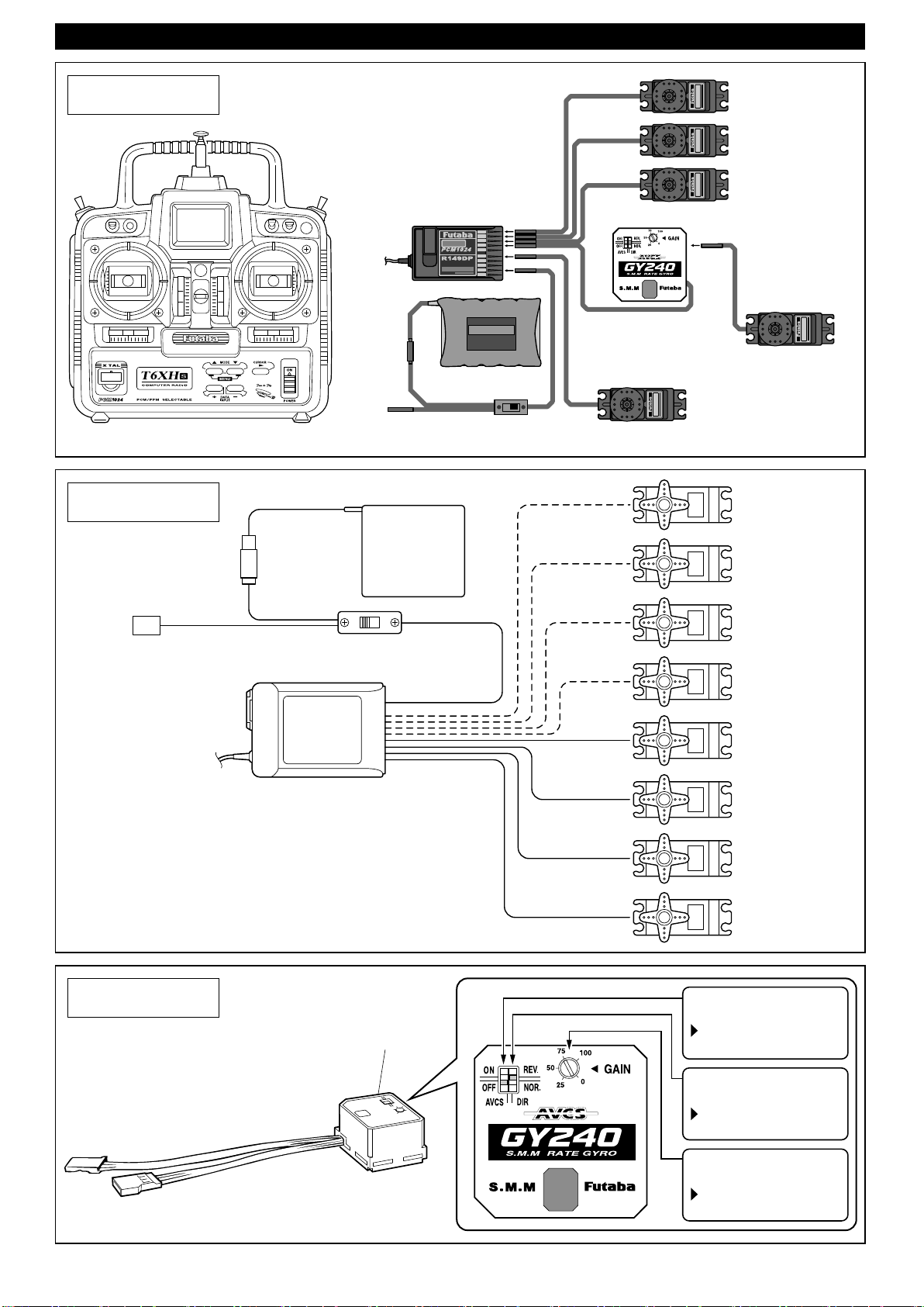
プロポの準備 RADIO PREPARATION
フタバの場合
Futaba Radio
JRの場合
JR Radio
受信機
Receiver
充電口
Terminal to charge
1
2
3
UAL
D
C
ONVERSION
4
5
PULSE CODE MODULATION
6
7
9 CHANNEL
RECEIVER
8
9/B
DSC
ニカド電池
Ni-cd Battery
受信機スイッチ
Receiver Switch
CH1
エルロンサーボ
Aileron Servo
CH2
エレベーターサーボ
ElevatorServo
CH3
スロットルサーボ
ThrottleServo
CH4 ラダーサーボ
Rudder Servo
CH6
ピッチサーボ
Pitch Servo
AUX 3
充電口
Terminal to charge
ジャイロ
Gyro
受信機スイッチ
Receiver Switch
受信機
Receiver
BATT
AUX 4
AUX 3AUX 2
AUX 1GEAR
RUDD
ELEV
AILE
THRO
ニカド電池
Ni-cd Battery
ジャイロ
Gyro
AUX 2
AUX 1
ピッチサーボ
Pitch Servo
GEAR
ギヤ
RUDD
ラダーサーボ
Rudder Servo
ELEV
エレベーターサーボ
ElevatorServo
AILE
エルロンサーボ
Aileron Servo
THRO
スロットルサーボ
ThrottleServo
AVCS切替
AVCSSwitch
OFF側にセットする。
Set to "OFF".
ジャイロ方向
GyroDirection
REV側にセットする。
Set to "REV".
ジャイロ感度
GyroGain
75にセットする。
Set to 75.
3
Page 6
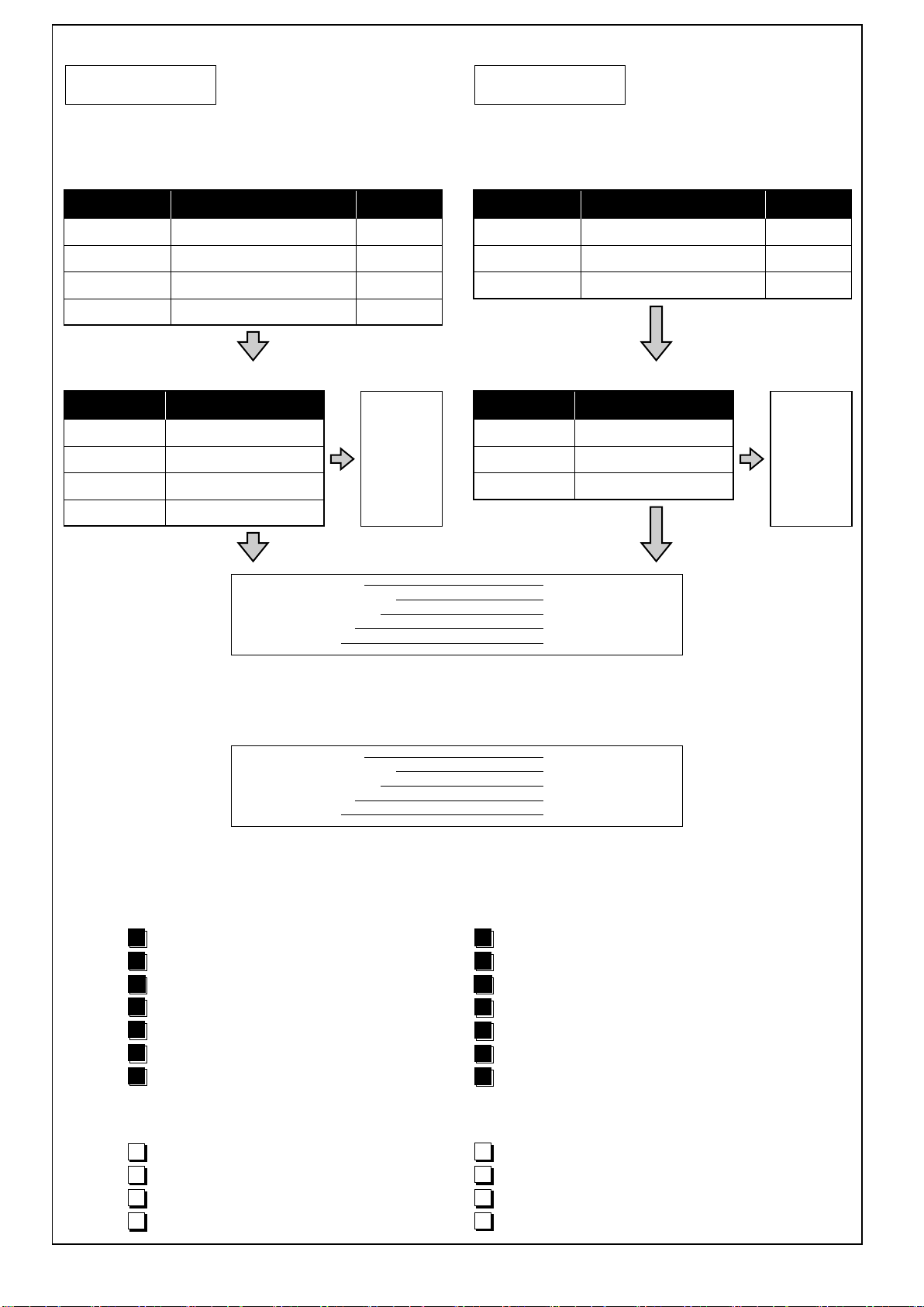
■EMS時のプロポ初期設定120°スワッシュモード(設定名と同じモードにする。)
フタバの場合
Futaba Radio
1CH、エルロン Aileron
2CH、エレベーター Elevator
3CH、スロットル Throttle
4CH、ラダー Rudder
6CH、ピッチ Pitch
プロポ名 設定項目 設定名
FF6s
FF8s
FF9
1024シリーズ
SWSH
PARAMETER→TYPEHELI
PARAMETER→TYPEHELI
MDL→SWH→SWASHTYP
●各チャンネルの動作方向と動作量
SWSH3
SR‑3
SR‑3
SR‑3
プロポ名 設定項目
FF6s
FF8s
FF9
1024シリーズ
SWSH
SWASH
SWASHAFR
SWH→SWASHTYP
エルロン
AILE
エレベーター
ELEV
ピッチ
PITCH
-65
-65
+65
JRの場合
JR Radio
1CH、スロットル Throttle
2CH、エルロン Aileron
3CH、エレベーター Elevator
4CH、ラダー Rudder
6CH、ピッチ Pitch
プロポ名 設定項目 設定名
MAX66II
3810
PCM10シリーズ
MIXCCP
SYSTEM→SWASHTYP
65SWASHMIX
●各チャンネルの動作方向と動作量
ON
3SERVOS
3SERVOS
プロポ名 設定項目
MAX66II
3810
PCM10シリーズ
MIXCCP→CH
SwashMix
65SWASHMIX
エルロン
AILE
エレベーター
ELEV
ピッチ
PITCH
-65
-65
+65
●リバーススイッチ(各社共通) Reverse Switch
エルロン Aileron
エレベーター Elevator
スロットル Throttle
ラダー Rudder
ピッチ Pitch
(※JRG410T、G460T等は、リバースになります。)
■MMS時のプロポ初期設定
●リバーススイッチ(各社共通) Reverse Switch
エルロン Aileron
エレベーター Elevator
スロットル Throttle
ラダー Rudder
ピッチ Pitch
(※JRG410T、G460T等は、リバースになります。)
サーボのニュ―トラル調整の手順
●始める時
1
各サーボ等を受信機に接続する。
トリムを中央にセットする。(送信機)
2
スイッチを入れる。(送信機)
3
4
各設定画面を開く。(送信機)
5
各設定を行う。(送信機)
スイッチを入れる。(受信機)
6
スティックを動かしてサーボが動いているか確認。
7
ノーマル Normal
ノーマル Normal
リバース Reverse
ノーマル Normal
リバース Reverse
リバース Reverse
ノーマル Normal
リバース Reverse
ノーマル Normal
リバース Reverse
●START
1
Connect servos to the receiver.
Set trims to center. (Transmitter)
2
Switch on the transmitter. (Transmitter)
3
Open the setting menu. (Transmitter)
4
Set up the data. (Transmitter)
5
Switch on the receiver. (Receiver)
6
Make sure the servos move according to
7
your transmitter inputs.
※
一部ジャイロによっては
※
ジャイロ方向の切り替え
によって、プロポ側の動
作方向を切り替える必要
があります。
(JR.G410T,G460T等)
Some transmitter also require
Gyro Direction Setting.
(JR G410T/G460T etc.)
※
●終わる時
送信機のスティックを中立にする。(送信機)
8
スイッチを切る。(受信機)
9
スイッチを切る。(送信機)
10
アンテナを縮める。(送信機)
11
●FINISH
Set transmitter sticks to neutral. (Transmitter)
8
Switch off the receiver. (Receiver)
9
Switch off the transmitter. (Transmitter)
10
Retract the antenna. (Transmitter)
11
4
Page 7
組立て前の注意(1) BEFORE YOU BEGIN (1)
組立てる前に説明書を良く読んで、おおよその構造を理解してから組立てに入ってください。
1
Read through the manual before you begin, so you will have an overall idea of what to do.
キットの内容をお確かめください。万一不良、不足がありましたら、お買い求めの販売店にご相談いただくか、
2
当社「ユーザー相談室」までご連絡ください。
Check all parts. If you find any defective or missing parts, contact your local dealer or our Kyosho Distributor.
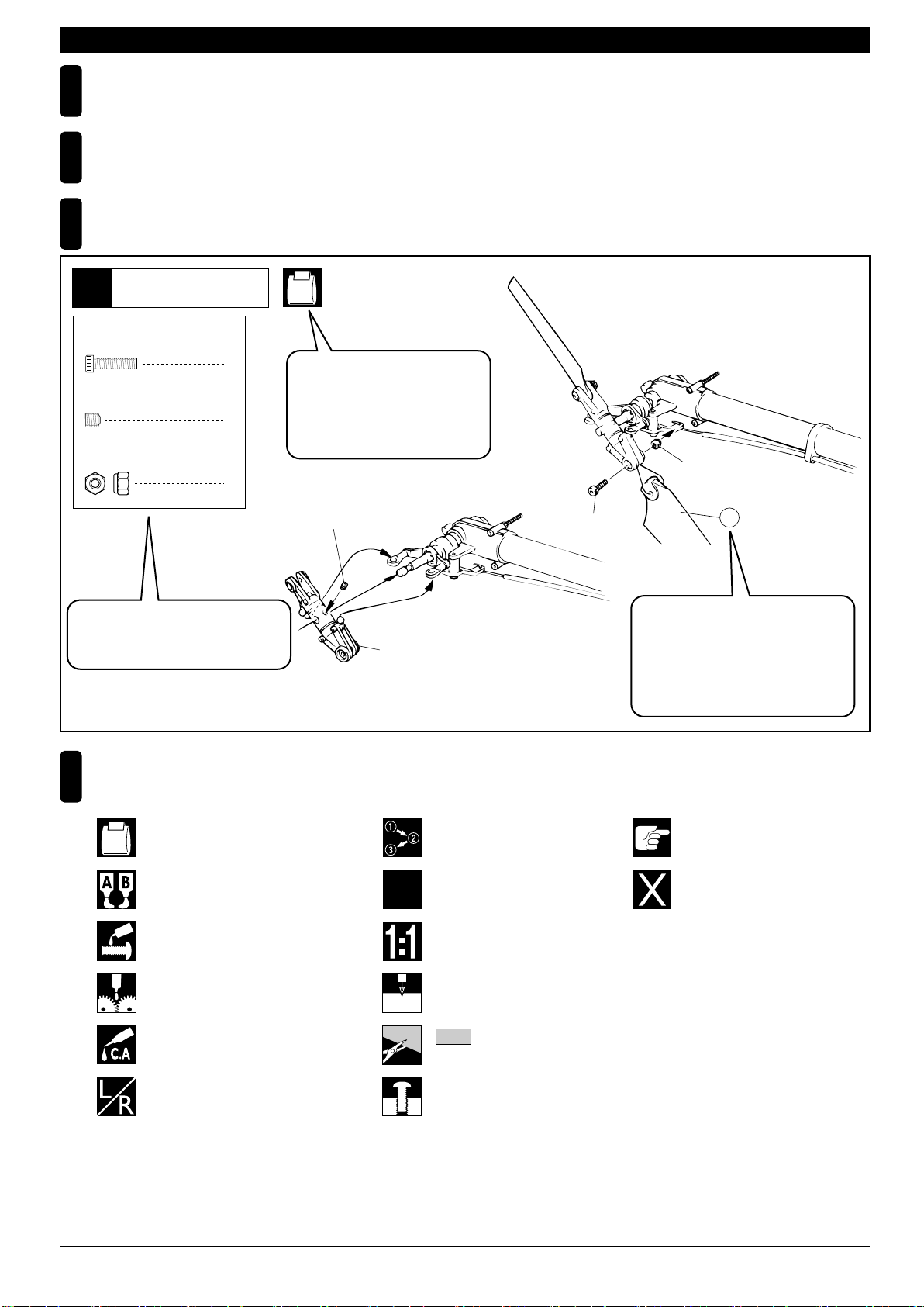
説明書の見かた
3
How to read the instruction manual:
〔説明例Example〕
テール
Tail
9
2.6 x 10mm キャップビス
3 x 3mm セットビス
2.6mm ナイロンナット
小物部品の名前、原寸図、使用数。
Key Number, Part Name, True-to-scale
Diagram, Quantity Used
Cap Screw
2
Set Screw
1
Nylon Nut
2
HH-2
説明書内では多くのマークが使用
されています。マークに注意して
組立てを進めてください。
This instruction manual uses several symbols. Please note them
during the entire assembly.
3 x 3mm
テールローターアッセンブリー
Tail Rotor Assembly
2.6 x 10mm
2.6mm
92
キット内の部品は、ビス類を除いてキー
No.が付けられています。スペアパーツを
購入する時はキーNo.を参照してください。
All parts except screws are identified by
key numbers. For purchasing spare parts,
find the key no. of the part needed in the
spare part list and refer to the left column
to look up the corresponding order no.
説明書に使われているマーク
4
Symbols used throughout the instruction manual, comprise:
使用する袋詰。
Part bags used.
エポキシ接着剤で接着する。
Apply epoxy glue.
ネジロック剤を塗る。
Apply threadlock (screw cement).
グリスを塗る。
Apply grease.
瞬間接着剤で接着する。
Apply instant glue (CA glue, super glue).
左右同じように組立てる。
Assemble left and right sides
the same way.
x2
2mm
番号の順に組立てる。
Assemble in the specified
order.
2セット組立てる(例)。
Assemble as many times as
specified (here: twice).
原寸図
True-to-scale diagram.
2mmの穴をあける(例)。
Drill holes with the specified
diameter (here: 2mm).
をカットする。
Cut off shaded portion.
仮止め。
Tempororarily tighten.
注意して組立てる所。
Pay close attention here!
別購入品
Must be purchased separately!
5
Page 8
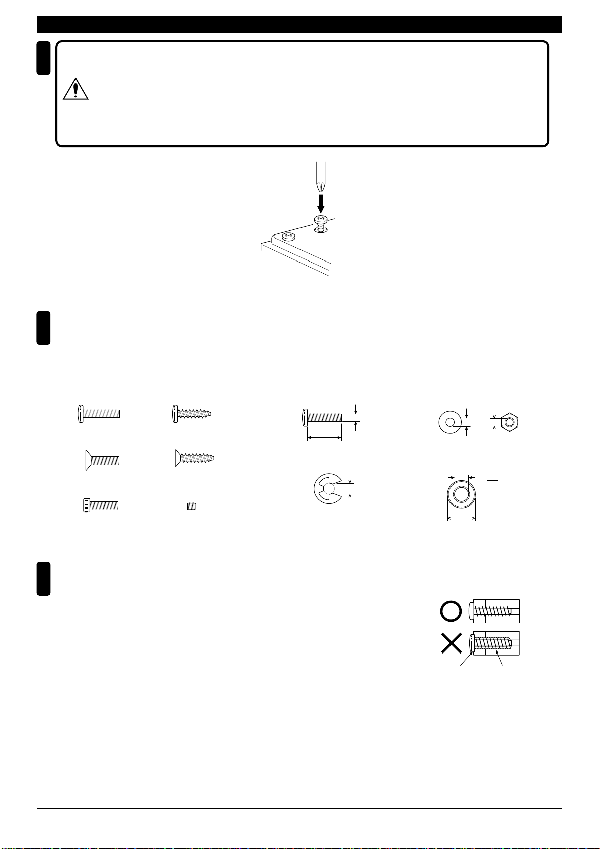
組立て前の注意(2) BEFORE YOU BEGIN (2)
5
キット内の部品の中には、組立て済みの部品があります。
念のためビス等のゆるみが無いか確認してから、組立ててください。
CAUTION: Inside the kit, you will find assemblies, i.e. sections that are pre-assembled
and hence consist of more than one part. To make sure these assemblies are safely
注意
assembled, check among others their screws for looseness.
Only then, build in the assemblies.
キットには、形や長さが違うビスや小物部品が多く入っています。説明書には原寸図がありますので確認してから
6
組立ててください。また、ビス類は多めに入っているものもありますので、予備としてお使いください。
This kit contains screws and hardware in different metric sizes and shapes. Before using them, check the screws on the true-to-scale diagrams
on the left side in each assembly step. Some screws are extras.
●ビスの種類 SCREWS
ビス Screw
サラビス
Flat Head (F/H) Screw
キャップビス
Cap Screw
TPビス
Self-tapping (TP) Screw
TPサラビス
TP F/H Screw
セットビス
Set Screw
●小物部品のサイズ例 OTHER HARDWARE
3x12mm ビス
Screw
3mm
12mm
E4 Eリング
E-ring
4mm
TPビスは、部品にネジを切りながらしめつけるビスです。しめこみが固い場合が
7
ありますが、部品が確実に固定されるまでしめこんでください。ただし、しめす
ぎるとネジがきかなくなりますので、部品が変形するまでしめないでください。
Self-tapping (TP) screws cut threads into the parts when being tightened. Excessive force may
permanently damage parts when tightening TP screws. It is recommended to stop tightening when
the part is attached or when some resistance is felt after the threaded portion enters the plastic.
3mm ワッシャー・ナット
Washer・Nut
3mm
5x10mm メタル・ベアリング
Metal Bushing・Bearing
5mm
10mm
Correct
Wrong
しめすぎ
Overtightened.
ビスがきかない
The threads are stripped.
6
Page 9
●
この組立て説明書はエンジン無し半完成(No.21135)/エンジン付き半完成(No.21136)共通の説明書です。
お買い上げいただいた商品に合わせて組立ては下記のように行ってください。
No.21135= 1 ~ 23 No.21136= 5 ~ 23
This instruction is for both Pre Assembled without Engine (#21135) and Pre Assembled with Engine (#21136) version.
Please follow right step as follows.
No.21135= 1 ~ 23 No.21136= 5 ~ 23
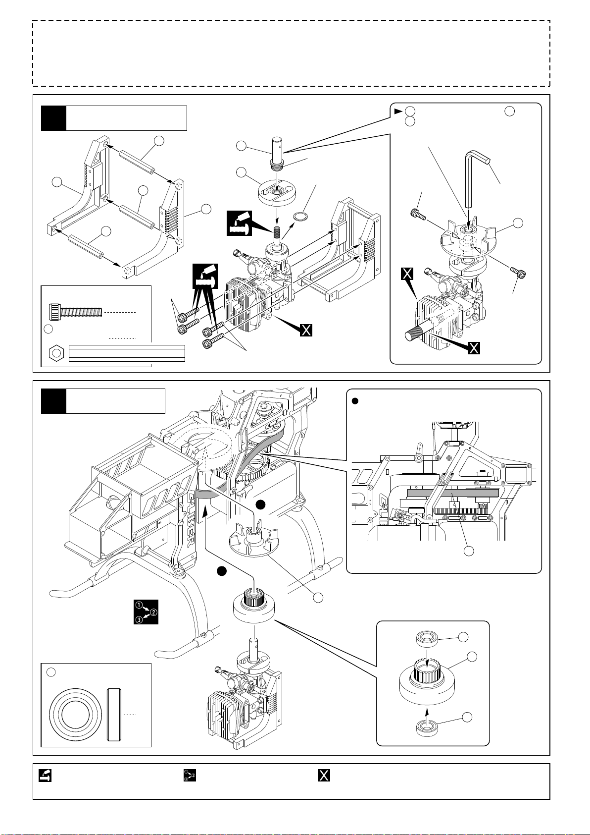
エンジン,エンジンマウント
Engine, Engine Mount
1
967
947
3 x 15mm
Cap Screw
947
クロスメンバー
Cross member
キャップビス
エンジン
Engine
2
947
4
3
947
3x15mm
966
952
886
3x15mm
逆ネジ
Reversed Screw
ワッシャーは不要
No need.
エンジンユニット
Engine Unit
正常時のエンジンとベルトの位置
The right position of the belt and engine
をエンジンに取り付ける際、 を一旦
952
に固定する。(
952
まない様にしっかり締める。)
Tighten the fan securely with screws.
3x6mm
エンジン始動時にゆる
890
六角レンチ(6mm)
Hex Wrench (6mm)
890
3x6mm
ピストンロック
Piston Lock
710
10 x 19 x 5mm
Ball Bearing
ネジロック剤を塗る。
Apply threadlocker (screw cement).
ベアリング
2
1
2
番号の順に組立てる。
Assemble in the specified order.
一旦外す。
890
Unscrew temporarily.
別購入品。
Must be purchased separately!
710
973
710
ベルト
Belt
887
7
Page 10
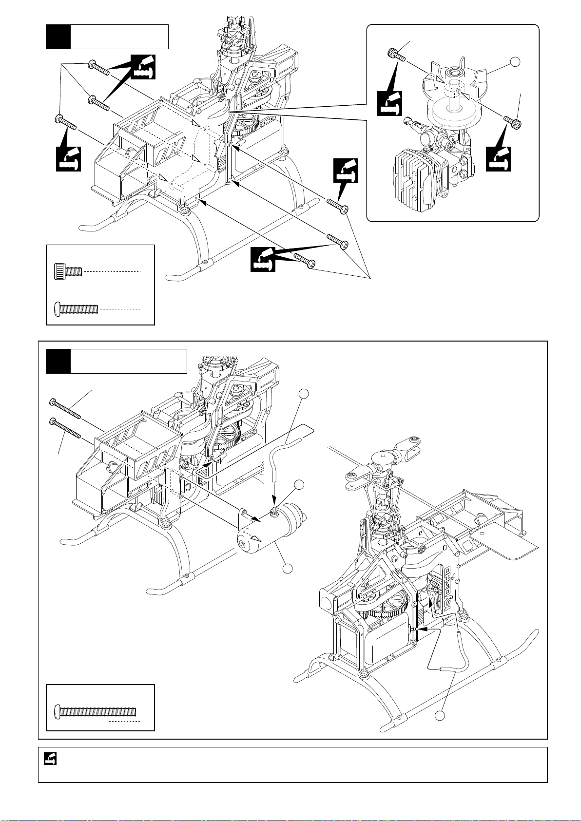
3
エンジン
Engine
3x6mm
3x14mm
3 x 6mm
Cap Screw
3 x 14mm
Screw
キャップビス
ビス
890
3x6mm
2
3x14mm
6
マフラー,シリコンチューブ
Muffler, Silicone Tube
4
3x28mm
3x28mm
635
シリコンチューブ(100mm)
Silicone Tube (100mm)
903
901
3 x 28mm
Screw
ネジロック剤を塗る。
Apply threadlocker (screw cement).
ビス
8
635
2
シリコンチューブ(100mm)
Silicone Tube (100mm)
Page 11
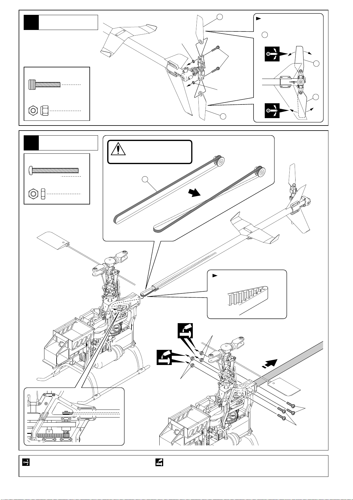
テールローター
Tail Rotor
5
3 x 15mm
Cap Screw
3mm
Nylon Nut
キャップビス
ナイロンナット
821A
3mm
3x15mm
軽く動く様に調整する。
向きに注意。
Tighten the screws ensuring
821A
can still move.
Note the direction.
821A
2
3mm
821A
テールパイプ
Tail Pipe
6
3 x 28mm
Screw
3mm
Nut
ビス
ナット
2
821A
ベルトのねじる方向に注意
CAUTION: Note the direction
for twisting.
注意
4
4
930
ベルトを折らないように注意。
Do not fold belt.
可動するように組立てる。
Ensure smooth, non-binding movement when assembling.
3mm
テールパイプを軽く引く
Pull Tail Pipe
3mm
3x28mm
3x28mm
ネジロック剤を塗る。
Apply threadlocker (screw cement).
9
Page 12
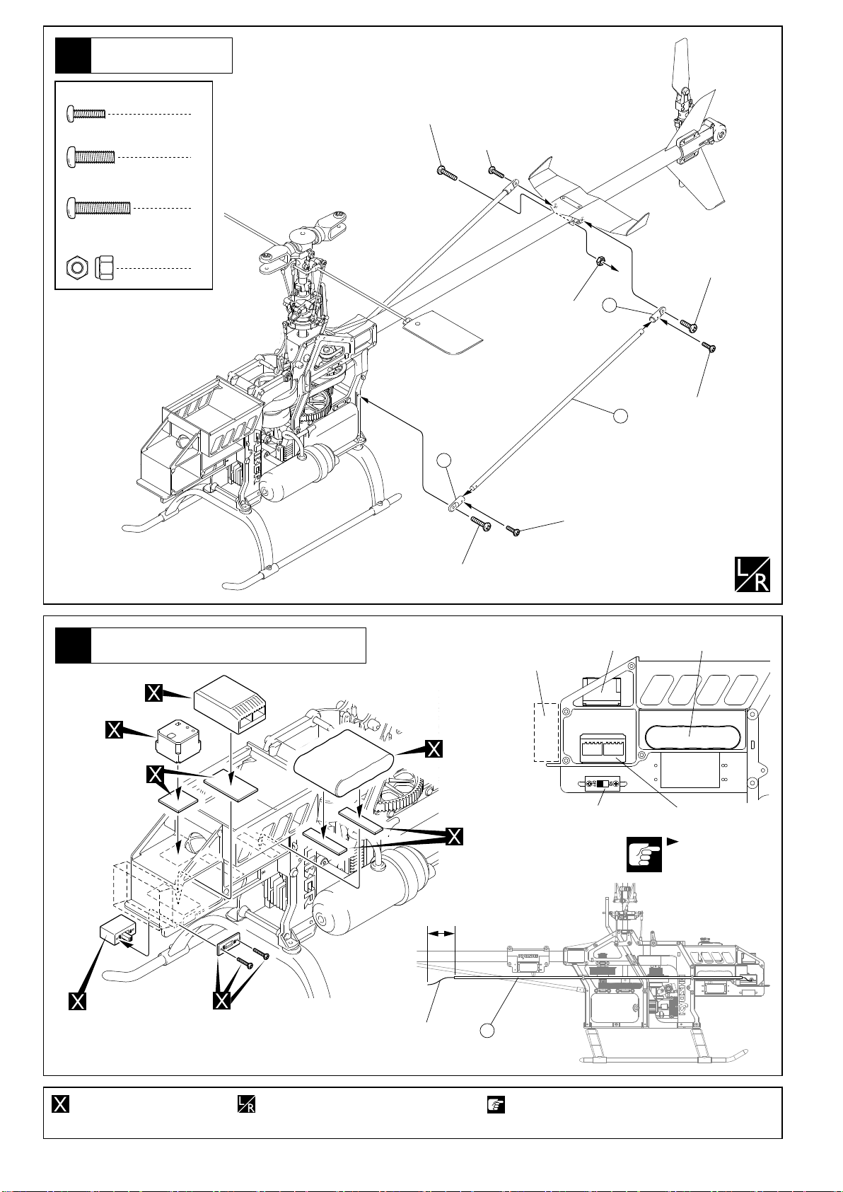
テールサポートパイプ
Tail Support Pipe
7
2 x 8mm
Screw
3 x 10mm
Screw
3 x 14mm
Screw
3mm
Nylon Nut
ビス
ビス
ビス
ナイロンナット
4
2
3
1
3x14mm
3x10mm
3mm
3x10mm
928
2x8mm
927
928
ジャイロ,受信機,バッテリー,スイッチの取付
Installing Gyro, Receiver, Battery, Switch
8
受信機
Receiver
ジャイロ
Gyro
両面テープ
Double-sided Tape
3x14mm
バッテリー
Battery
20~30mm
ジャイロアンプ
Gyro Amp
両面テープ
Double-sided Tape
2x8mm
スイッチ
Switch
ジャイロ
Gyro
バッテリー
Battery
受信機
Receiver
プロポの説明書を参考
に振動対策を行う。
Refer Instruction Manual
included radio set to
prevent vibration.
スイッチ
Switch
別購入品。
Must be purchased separately!
スイッチ
10
Switch
左右同じように組立てる。
Assemble left and right sides the same way.
975
アンテナパイプアンテナ
Antenna PipeAntenna
注意して組立てる所。
Pay close attention here!
Page 13

ラダーサーボ
Rudder Servo
9
3mm
3mm
932
3x10mm
931
932
3x10mm
サーボに合わせて取付位置を変える。
Select the hole by servo size you use.
a
長い場合 短い場合
In case of long In case of short
a b
b
2 x 8mm
TP Screw
954
3 x 10mm
Screw
3mm
Nut
2.6 x 10mm
TP Screw
2.6mm
Washer
TPビス
リンケージボール
Linkage Ball
ビス
ナット
TPビス
ワッシャー
10~14mm
929
ラダーサーボ
Rudder Control Servo
1
2.6mm
1
4
4
4
4
2.6mm
が真直ぐ無理なくスムーズに動く様、サーボによって
929
リンケージ方法を選んでください。
Choose by which servo you use for smooth linkage.
上から見た図 上から見た図
Top View Top View
サーボホーン
Servo Horn
テールパイプ テールパイプ
Tail Pipe Tail Pipe
2.6x10mm
2.6x10mm
約5mm
approx. 5mm
929
サーボホーン
Servo Horn
954
885
2x8mm
885
ラダーサーボ・テールリンケージガイド
Rudder Servo, Tail Linkage Guide
10
2 x 8mm
TP Screw
TPビス
2
2x8mm
933
仮止め。
Tentatively tighten.
別購入品。
Must be purchased separately!
リード線の固定
Rudder Servo Code
2x8mm
933
ネジロック剤を塗る。
Apply threadlocker (screw cement).
11
Page 14

ラダーサーボ・テールリンケージガイド
Rudder Servo, Tail Linkage Guide
11
を2x8mmTPビスを締め込み固定する。
933
Tighten 2x8 TP screws of Rod guide in the directed position.
180mm 80mm
90
< >ニュートラル
< >Neutral
933
2x8mm
この溝に を通す。
must be on the groove.
929
2x8mm
929
933
929
90
上から見た図
Top View
< >ニュートラル
< >Neutral
スロットルサーボ
Throttle Servo
12
2.6 x 10mm
TP Screw
2.6mm
Washer
2 x 8mm
Screw
2mm
Nut
954
リンケージボール
Linkage Ball
2x8mm
TPビス
ワッシャー
ビス
ナット
954
4
4
1
1
2.6mm
1
2.6x10mm
2.6x10mm
10~11mm
2.6mm
スロットルサーボ
Throttle Control Servo
2mm
をカットする。 別購入品。
Cut off shaded portion. Must be purchased separately!
12
Page 15

スロットルサーボ
Throttle Servo
13
2 x 8mm
Screw
2mm
Nut
954
リンケージボール
Linkage Ball
ビス
ナット
52mm
1
1
1
957
フィクストロッド(52mm)
Fixed Rod (52mm)
2mm
10~11mm
954
プロポスティック中立の時(スロットルカーブ50%時)
Move all sticks neutral (center) position. (When throttle curve 50%)
957
2x8mm
エンジンスロットルの作動範囲に合わせて、スロットル
サーボの作動範囲をプロポ側で調整する。
Adjust the throttle servo operation range of a transmitter
according to the range of operation of a carburetor.
A A'
A = A'
A A'
13
Page 16

リンケージ(EMS)
Linkage (EMS)
14
2 x 8mm
Screw
2mm
Nut
954
ビス
ナット
リンケージボール
Linkage Ball
(MMSの場合はP15へ)EMSの場合
x3
3
3
3
約10〜11mm
approx. 10~11mm
15
ピッチサーボ エレベーターサーボ エルロンサーボ
Pitch Servo Elevator Control Servo Aileron Servo
2x8mm
2mm
For EMS (Move to P15 for MMS)
15
2x8mm
954
954
2mm
2x8mm
954
2mm
2.6 x 10mm
TP Screw
2 x 8mm
TP Screw
3 x 14mm
Screw
954
3x6x0.5mm
Washer
TPビス
TPビス
ビス
リンケージボール
Linkage Ball
ワッシャー
エレベーターサーボ
Elevator Control Servo
エルロンサーボ
Aileron Servo
18
5
2
5
2
32mm
914
3x5x4mm
Collar
714
3x7x3mm
ピッチサーボ
Pitch Servo
カラー
2
ベアリング
Ball Bearing
4
2.6x10mm
921
2.6x10mm
919
フィクストロッド(32mm)
956
Fixed Rod (32mm)
2.6x10mm
919
プロポスティック全て中立
(ピッチカーブ50%時)
Move all sticks neutral
(center) position.
(When pitch curve 50%)
923
平行
Parallel
2x8mmTP
954
2x8mm
TP
3mm
714
922
956
954
914
フィクストロッド
(32mm)
Fixed Rod
(32mm)
954
2x8mm
TP
714
3x14mm
959
フィクストロッド(72mm)
Fixed Rod (72mm)
960
フィクストロッド(128mm)
Fixed Rod (128mm)
72mm
128mm
をカットする。 別購入品。
Cut off shaded portion. Must be purchased
separately!
14
959
フィクストロッド(72mm)
Fixed Rod (72mm)
左右同じように組立てる。
Assemble left and right
sides the same way.
3セット組立てる(例)。
x3
Assemble as many
times as specified.
960
フィクストロッド
(128mm)
Fixed Rod
(128mm)
960
フィクストロッド(128mm)
Fixed Rod (128mm)
Page 17

リンケージ(MMS)
Linkage (MMS)
15
2 x 8mm
Screw
2mm
Nut
954
ビス
ナット
リンケージボール
Linkage Ball
MMSの場合
約10〜11mm
approx. 10~11mm
4
4
4
約20~22mm
approx. 20~22mm
x1
x2
For MMS
ピッチサーボ エレベーターサーボエルロンサーボ
Pitch Servo Elevator Control ServoAileron Servo
2x8mm
2mm
2x8mm
954
954
2mm
2x8mm
954
2mm
2mm
954
2x8mm
2.6 x 10mm
TP Screw
2 x 8mm
TP Screw
3 x 14mm
Screw
954
3x6x0.5mm
Washer
958
TPビス
18
TPビス
5
ビス
2
リンケージボール
Linkage Ball
5
ワッシャー
2
エレベーターサーボ
Elevator Control Servo
2.3 x 30mm
Adjust Rod
アジャストロッド
914
3x5x4mm
Collar
714
3x7x3mm
ピッチサーボ
Pitch Servo
エルロンサーボ
Aileron Servo
32mm
1
カラー
2
ベアリング
Ball Bearing
8
2.6x10mm
2.6x10mm
919
714
920
956
フィクストロッド(32mm)
Fixed Rod (32mm)
2.6x10mm
919
714
714
プロポスティック全て中立
(ピッチカーブ50%時)
Move all sticks neutral
(center) position.
(When pitch curve 50%)
960
フィクストロッド(128mm)
Fixed Rod (128mm)
2x8mmTP
954
923
平行
Parallel
3mm
MMSは が前後に移動しま
※
2x8mm
TP
920
すので、サーボのリード線に
は必ず余裕を取ってください。
Note is movable for MMS.
920
Cord must be long enough.
フィクストロッド
956
(32mm)
Fixed Rod
(32mm)
954
954
714
922
914
714
2x8mmTP
3x14mm
959
フィクストロッド
(72mm)
Fixed Rod
(72mm)
18.5mm
958
958
885
959
72mm
128mm
をカットする。 別購入品。 左右同じように組立てる。
Cut off shaded portion. Must be purchased separately! Assemble left and right
フィクストロッド(72mm)
Fixed Rod (72mm)
sides the same way.
2セット組立てる(例)。
x2
Assemble as many
times as specified.
960
フィクストロッド
(128mm)
Fixed Rod
(128mm)
960
フィクストロッド(128mm)
Fixed Rod (128mm)
15
Page 18

プロポのピッチカーブ
Pitch Curve Adjustment
16
スワッシュプレートを水平になるように、送信機のサブトリムを使い調整する。
Make swash plate horizontal by adjust sub trims of the transmitter.
< >
ピッチの測定
< >Adjustment of a pitch
ピッチ角の参考値
Pitch reference table
メインローターを水平にした状態にて測定する。
Place Main Rotor horizontally.
スティック位置 ロー 中央 ハイ
Stick Position Low Center High
ホバリング練習
Hovering
上空飛行
Normal Flight
ループ、ストールターン
Loop / Stall Turns
ロール
Roll
3D(アクロバット)フライト
3D (Aerobatics)
オートローテーション
Autorotation
初めての方はP16- を参照してください。
※
A beginner needs to refer to Page 16- .
0° 6° 10°
-2° 6° 9°
-3° 4° 9°
-6° 2° 9°
-8° 0° 9°
-2~-3° 6° 12°
17
ピッチロッド
Pitch Rod
スワッシュプレート
Swash plate
水平
Horizontal
17
1.5mm
この状態でスワッシュプレート
に合わせてエルロン、エレベー
ターの最大動作量を調整します。
In this state adjust the amount
of the maximum operation of
aileron lever and elevator lever,
unite with swash plate moving.
スタビライザーバーをテールパイプと平行になるよう支えなが
ら、メインローターに取付任意の角度に設定したピッチゲージ
の平面が、スタビライザーバーと平行になるよう調整する。
Use a pitch gauge, supporting stabilizer bar so that it may
become parallel to a tail pipe.
平行
Parallel
平行
Parallel
ピッチの調整
Pitch curve adjustment
17
a
< >FRS
< >ミキシングレバーの設定例
< >Setting of the mixing lever
878
2
884
1
a
< >
トレーニングセーフティバーモードの場合
< >Training mode with safety bar
スロットル&ピッチスティックと スワッシュ
プレートと ラジアスアームの刻印が合うよう
に、送信機を調整する。
Adjust the throttle and pitch stick movement of
transmitter so that the tail bar of swash plate
and marking of radius arm may suit each point.
911
909
1
組立済標準位置。
操作性と運動性重視。
Normal position, quick
response good for 3D.
ピッチ角の調整
Pitch Adjustment
Hiピッチ 約10°
Hi Pitch
ホバリングピッチ 約6°
Hovering Pitch approx. 6°
Loピッチ 約0°
Lo Pitch approx. 0°
approx. 10°
a
2
< >RRS
< >
トレーニングセーフティバーモード
セーフティバーモード。
安定性重視の為、蛇角が鈍感。
(経験者が飛行する場合は、
エルロン、エレベーターの
EXPを敏感に設定し、D/R
を70%位にする。)
Training mode with safety bar,
insensitive increase stability.
(If the experienced flyer fly with
this mode, adjust Aileron and
Elevator EXP to sensitive and
70% D/R.)
< >Training mode with safety bar
トレーニングセーフティバーを使用する場合、右記
のように変更することで自立安定性が向上します。
When using Safety bar, change the pivot hole as
shown in the following figure, stability will increase.
ピッチロッド
Pitch Rod
0mm
16
(ハイ)
(High)
(ホバリング)
(Hovering)
(ロー)
(Low)
909
スワッシュプレート
Swash plate
911
ラジアスアーム
Radius arm
Page 19

ボディ
Body Shell
18
スイッチ用の穴位置。
Position of Switch holes.
898
裏面をカットする。
Cut away only inside.
19
デカール
Decals
23 24
(
)
(
21 22
15mm
15mm
100mm 25mm
図の位置に から順にデカールをはる。1
Apply the decals to the positions
indicated in numerical order.
カッコの中は反対側用のデカールナンバーです。
The decal numbers between brackets
are only for the opposite side.
(
(
)
(
)
(
2625
1 2
3 4
)
16 15
)
17 18
)
(
)
(
5 6
をカットする。
Cut off shaded portion.
9
10
)
(
)
(
)
(
11 12
7 8
左右同じように組立てる。
Assemble left and right sides the same way.
13 14
)
上から見た図
Top View
(
(
)
16
15
19 20
)
17
Page 20

20
ボディ
Body Shell
3 x 15mm
Cap Screw
961
ボディーマウントワッシャー
Body Mount Washer
951
グロメット
Grommet
キャップビス
Body Shell
951
ボディ
グロメット
951
Grommet
951
948
949
951
961
グロメット
951
Grommet
ボディ
Body Shell
961
3 x 15mm
No.21137
950
No.21135
949
948
3 x 15mm
4
No.21137
961
950
4
No.21135
4
951
メインローター
Main Rotor
21
805
ドラッグボルト
Drag Bolt
4mm
ナイロンナット
Nylon Nut
メインローター トラッキングテープデカール グリップ
Main RotorGrip
2
トラッキングテープのある方にデカールを貼る。
2
(フライトコンディション維持の為、メインローター
を毎回同じグリップに取付ける。)
Apply Decals on the same side of the tracking tape applied.
(Attach Main Rotor on to the same side of Grip all the time.)
Tracking TapeDecal
軽く動くように調整する。
Tighten the drag bolt
ensuring main rotors
can still move.
805 805
4mm
4mm
18
Page 21

取扱いの注意 OPERATING YOUR MODEL SAFELY
次のような時、場所では飛行させない。思わぬ事故の原因になります。
WARNING: Do NOT operate the helicopter in the following places and situations:
警告
(Non-observance may lead to accidents!)
●周囲に人がいなくて、広い安全な場所で!
1.近くに小さな子供がいたり、人の多い場所では飛行させない。
2.民家の近くや公園などでは飛行させない。
3.室内やせまいところでは飛行させない。。
4.強風時、雨天時には飛行させない。
※人にケガをさせる原因になります。また、物をこわしたり、
他人の迷惑になります。
Operate the helicopter in spacious areas with no
people around! Do NOT operate it:
1. in places where children and many people gather!
2. in residential districts and parks!
3. indoors and in limited space!
4. when there is a strong wind or when it is raining!
*
Non-observance may account for personal injury and property
damage!
●プロポ関係の電池残量は常にチェックする。
電池が減ってくると電波の送・受信が弱くコントロール
ができなくなり、墜落や事故の原因になります。
Always check the radio batteries!
If the radio batteries get weaker, transmission and reception
decrease. You may lose control of your model when operating it under such conditions. This may lead to accidents!
●近くで無線操縦模型を楽しんでいる人がいる。
同じバンドでの同時飛行はできません。電波が混信して
コントロールができなくなり、墜落や事故の原因になります。
Keep in mind that people around you may also
operate a radio control model!
NEVER share the same frequency
with somebody else at the same
time! Signals will be mixed and
you will lose control of your model.
This may lead to accidents!
●へりの動きがおかしい??とき。
すぐに飛行を中止しておかしい原因を調べる、原因不明のまま
飛行させると、思わぬ故障や事故の原因になります。
When the model behaves strangely . . .!
Immediately stop the model and check the reason. As long as the
problem is not cleared, do NOT operate it! This may lead to further
trouble and unforeseen accidents!
事故やケガ等の危険防止のため、次のことを必ずお守りください。
WARNING: for preventing accidents and personal injury, be sure to observe the following:
警告
●飛行前に、ビス等のゆるみをチェックする。
ビス1本のゆるみが事故に
つながります。
Before flying, ensure
all screws are tight!
A single loose screw may
account for accidents!
●亀裂や傷のついた部品は、新品と交換する。
墜落や事故の原因になります。
Replace all parts with defects or being
cracked with new ones!
Defect and cracked
parts lead to accidents
and crashs!
●回転しているローターには近づかない。
接触事故を防ぐために、10m以上機体から離れること。
NEVER approach a rotor
spinning at high speed!
Stand at least 10m away from
the rotor for injury prevention!
●飛行直後は、エンジン、マフラー周辺は高温になって
いるので、すぐにはさわらない。
ヤケドの原因になります。
Right after use, do NOT touch the engine
and muffler generating high temperatures!
You may get seriously burned touching the engine or muffler!
10m
●燃料は、模型用グロー燃料を必ず使用する。
ガソリンや灯油の使用は、火災等の事故の原因になります。
ONLY use glow fuel for radio control models!
Because the use of gasoline and kerosene in R/C models ac-counts for fires, do NOT use them!
●燃料は、引火性があります。
1.火気のあるところや室内では絶対に使用しない。
2.保管は、キャップをしっかりしめ、幼児の手の届かない冷暗
所に置くこと。
3.使用後の空缶は、火中には投げ入れない。爆発の原因になり
ます。
Fuel is highly inflammable and
high-explosive!
1. NEVER use fuel indoors or in places
with open fires and sources of heat!
2. Store fuel ONLY in cool, dry and dark
places out of children's reach! Tightly shut the cap!
3. Do NOT dispose of empty fuel cans into a fire! There is
danger of explosion!
●燃料は、飲んだり、目に入れたりしない。
万一、事故が起きた場合は、吐かせる、洗眼する等をした後、
すぐに医師の診察を受けてください。
NEITHER swallow fuel NOR let it into your eyes!
When fuel is swallowed,
in-duce vomit-ing.
When fuel gets into
eyes, rinse them and
consult an
●定められたメンテナンスをおこなう。
Observe the necessary maintenance!
19
Page 22

プロポのスティックの動きとヘリコプターの運動
CALIBER 30 Control Reactions
●プロポの操作によるヘリコプターの動きを充分に
理解してから飛行をおこなってください。
Below are listed the reactions of the CALIBER 30
according to your inputs.
ヘリコプターの動き HELICOPTER RESPONSE ヘリコプターの動き HELICOPTER RESPONSE
エンジンの回転が上がりメインローターブレードの
ピッチが大きくなり上昇する。
Engine rpm and the main rotor pitch increase. As a
result, the helicopter lifts up.
2
左へ移動。
Moves left.
1
左へかたむく。
Tilts left.
プロポの操作
CONTROL STICK POSITION (MODE 1)
スロットル
Throttle
ハイ
High
ロー
Low
エルロン
Aileron
左
Left
右
Right
エンジンの回転が下がりメインローターブレードの
ピッチが少なくなり下降する。
Engine rpm and the main rotor pitch decrease. As a
result, the helicopter descends.
2
右へ移動。
Moves right.
1
右へかたむく。
Tilts right.
1
2
エレベーター
Elevator
2
1
ダウン
Down
1
前進または
2
スピードがあれば降下。
1
Moves forward.
2
With airspeed, the helicopter descends.
アップ
Up
1
後進またはブレーキ
2
スピードがあれば上昇。
1
Loses airspeed or moves backward.
2
With airspeed, the helicopter lifts up.
ラダー
Rudder
左
Left
テールローターのピッチを変えることで
機首を左へ振らせる。
By changing the tail rotor pitch, the
nose moves left.
右
Right
テールローターのピッチを変えることで
機首を右へ振らせる。
By changing the tail rotor pitch, the
nose moves right.
調整・飛行させる前にかならずお読みください。 Prior to adjusting & operating, observe the following:
●メインローターが回転しますので、調整・飛行は周りに人がいない屋外でおこなってください。
WARNING: Always operate the helicopter outdoors out of people's reach as the main rotor rotates at high rpm!
警告
●機体の調整中は、接触事故等を防ぐため、必ず機体から10m以上離れてください。
WARNING: While adjusting, stand at least 10 meters apart from the helicopter!
●無線操縦ヘリコプターが初めてという方は、機体の調整等を経験者のアドバイスを受けながら確実に組立ててください。
中途半端な組上がりの機体を飛行させるのは、大変危険です。
Novice R/C helicopter pilots should always seek advice from experienced pilots for hints in assembly and pre-flight adjust-
ments! Note that a badly assembled or insufficiently adjusted helicopter is a safety hazard!
●無線操縦ヘリコプターが初めてという方には、単独飛行はできませんので、必ず経験者の指導を受けてください。
In the beginning, novice R/C helicopter pilots should always be assisted by an experienced pilot and never fly alone!
●機体の破損等を防ぐため、スロットルスティックの操作はローから少しずつ上げてください。
For injury prevention, move the throttle control stick only slowly from low to high!
●プロポの電源スイッチを入れる時、または切る時は必ず下記の順番を守ってください。
When switching the radio ON or OFF, always proceed in the following order:
スイッチを入れる時
1
スロットルスティックをいちばん下(ロー)まで下げておく。
2
送信機のスイッチを入れる。
3
受信機のスイッチを入れる。
(ジャイロによってはニュートラルが出るまで待つ)
4
エンジンを始動する。
スイッチを切る時
1
エンジンを止める。
2
受信機のスイッチを切る。
3
送信機のスイッチを切る。
When switching ON:
1
Position the throttle control stick (transmitter) entirely to low.
2
Switch on the transmitter.
3
Switch on the receiver.
(Wait for neutral, depending on gyro.)
4
Start / Crank the engine.
When switching OFF:
1
Stop the engine.
2
Switch off the receiver.
3
Switch off the transmitter.
20
Page 23

飛行前のチェック
Checklist before flying
でピッチが小さくなる。
でピッチが大きくなる。
でスワッシュプレートが右にかたむく。
でスワッシュプレートが左にかたむく。
でスワッシュプレートが後ろにかたむく。
でスワッシュプレートが前にかたむく。
With , the main rotor pitch
becomes smaller.
With , the main rotor pitch
becomes bigger.
With , the swashplate tilts right.
With , the swashplate tilts left.
With , the swashplate tilts back.
With , the swashplate tilts fore.
でスライドリングが左に移動。
With , the slide ring moves left.
でスライドリングが右に移動。
With , the slide ring moves right.
エンジンの始動(1)
STARTING THE ENGINE (1)
電池の充電。 Charging radio batteries
1
プロポの電池は充分に充電しておくこと。送信機に乾電池を
使用している場合は新品に入れかえること。
With rechargeable radio batteries, charge them to full capacity.
With dry cells used in the transmitter, replace them with new ones.
機体の確認。 Checking the helicopter
2
ビス類は確実にしまっているか、もう一度確認すること。
Ensure that all screws, nuts, etc. are securely tightened.
燃料給油。 Refuelling
3
給油中はゴミが入らないように注意すること。
When filling up the tank, ensure that no dirt enters the tank
as well.
ニードル調整。 Basic Needle Setting
4
エンジンのニードルをいっぱいまでしめてから、指定された量だけゆる
める。(エンジンの取扱いは、エンジン付属の説明書をお読みください。)
Entirely tighten the needle, then unscrew it as many turns as specified
in the engine instruction manual.
プロポのスイッチを入れる。 Radio Activation
5
スロットルスティックは、ローにし、スロットルトリムは中央に
する。
Pull down the engine control stick and center the engine control trim.
トリムを中立に
3
Center the trim.
1
2
スティックを下に
2
Pull down the engine control stick.
警告
●プロポが誤動作したり動かない場合は、原因を探し、
解決するまでエンジンは絶対に始動させない。
WARNING: With radio glitches or a helicopter that
will not ÒmoveÓ, find out the reason. Do not start the
engine before finding and solving the problem!
スイッチをON
1
Switch on.
21
Page 24

エンジンの始動(2)
STARTING THE ENGINE (2)
エンジンが始動した時にローターが回転しないように、
ローターヘッドを手でしっかり固定する。
When the engine starts, take hold of the rotor head so
the rotor blades will not rotate.
プラグヒート。
6
プラグヒーターの電池の残量は常にチェックする。
Plug Heating
Always check the dry batteries used in the plug heater.
エンジン始動。
7
スターターが図の方向に回転するか確認する。
(逆に回転する場合は を逆にする)。
Engine Starting
Ensure the engine starter is rotating into the direction illustrated.
(If rotating into the opposite direction, reverse the and clips.)
エンジンを止める時は。
8
スロットルスティックとトリムを一番下まで下げる。
それでも止まらない時は、燃料パイプをエンジンからぬく。
Engine Stopping
Pull down the engine control stick and the trim.
If the engine still does not stop, pull out the fuel pipe from the engine.
トラッキング調整
TrackingAdjustment
左右のメインローターブレードのピッチ角をそろえることを
●
トラッキング調整といいます。
The tracking adjustment consists in making the main rotor pitch
on both blades equal.
スロットルスティックを少しずつ上げ機体を真横から見る。
Slowly pull up the throttle control stick.
Look at the blades directly from the side.
2枚のメインローターが、
If both main rotor blades look like in:
のように1枚に見えればOK。
(both blades travel in the same plane), no further adjusting is needed.
のように2枚に見える時は、下記の調整をおこなう。
(both blades track separately), further adjusting is needed.
RRS(トレーニングセーフティバーモード)の場合、
デカールを貼ったローターを基準にして、もう一方のローターが、
For RRS take the blade with the tracking tape as a base.
下に見える時は、ピッチロッドのボールエンドを右に1/2回転回し縮める(短くする)。
If the other blade (without the tracking tape) tracks lower, rotate
the ball end of the pitch rod half a turn right.
上に見える時は、ピッチロッドのボールエンドを左に1/2回転回し伸ばす(長くする)。
If the other blade (without the tracking tape) tracks higher, rotate
the ball end of the pitch rod half a turn left.
以上の調整を のようになるまでおこなってください。
Proceed the same way until both main rotor blades will travel in
the same plane as in .
※FRS(工場出荷時)の場合、動作が逆になります。
Be sure that operation becomes reverse in FRS.
10m以上
10m away
ピッチロッド
Pitch Rod
角度が減る。
Main rotor pitch decreases.
角度が増える。
Main rotor pitch increases.
22
●メインローターが回転しますので、調整・飛行は周りに人がいない屋外でおこなってください。
WARNING: Always operate the helicopter outdoors out of people's reach as the main rotor rotates at high rpm!
●機体の調整中は、接触事故等を防ぐため、必ず機体から10m以上離れてください。
警告
WARNING: While adjusting, stand at least 10 meters apart from the helicopter!
Page 25

トリム調整
Trim Adjustment
調整や練習飛行は、無風または微風の時におこなう。
NOTICE: Adjust and practice flying only when there is a weak wind or no wind.
注意
● 浮上する時の機体の傾きは、トリムレバーで調整します。
Correct any yawing, rolling or pitching of the helicopter during
take offs with the trims.
● 機体が浮上しようとする時、下図の 〜 のように傾く時は、
送信機のそれぞれのトリムレバーを 〜 の方向に調整します。
As the engine speed increases and the helicopter is close to taking off,
the following tendencies may be noticed for the helicopter to yaw
( or ), to roll ( or ) or to pitch ( or ) instead of lifting
straight up. If this happens, adjust the different trims on the transmitter
so the helicopter lifts straight up.
ホバリング練習(1)
Hover‑Lesson1
● ホバリング練習の前に、次のことを覚えておくと、上達が早く
なります。
Observe the following basics before practicing the hover. It will
make things a lot easier!
機体は、風にまっすぐ向けること。
Direct the helicopter into the wind.
横風や、追い風は、操縦が難しくなります。
With lateral and tail winds, operation becomes difficult.
テール部は見ずに、機首を見ること。
Do not watch the tail, watch the nose of the helicopter.
前傾姿勢で着地する。
後ろから着地すると、メインローターや、テールブームが破損しや
すくなります。
Nose-in when landing
When landing, the helicopter should touch ground with the nose first.
If touching ground with the tail first, the main rotor or tail boom may
be damaged.
風 Wind
●メインローターが回転しますので、調整・飛行は周りに人がいない屋外でおこなってください。
WARNING: Always operate the helicopter outdoors out of people's reach as the main rotor rotates at high rpm!
●機体の調整中は、接触事故等を防ぐため、必ず機体から10m以上離れてください。
警告
WARNING: While adjusting, stand at least 10 meters apart from the helicopter!
23
Page 26

ホバリング練習(2)
Hover-Lesson 2
● ヘリコプターをホバリングさせるには、常に操縦している
ことが必要です。操縦している指が、自然に反応するように、
根気よく練習してください。
Hovering necessitates constant control. Repeat practicing the
hover until your fingers get used to doing the controls on the
transmitter.
ヘリコプターを風上に向けて置き、その後方に立つ。
スロットルスティックを少しずつ上げ、機体が5〜10cmぐらい浮上
したら、スロットルスティックを少しずつ下げ着陸させる。
Direct the helicopter into the wind. Stand behind the helicopter. Raise
the throttle control stick a little, making the helicopter hover at a height
of 5 ~ 10 cm. Then, decrease engine speed and safely land it.
この練習を繰り返し、高度を少しずつ上げていく。
次に浮上したら、前方に着地するように操縦する。
Repeat this exercise and by increasing the altitude gradually. Next,
try to land the helicopter a little ahead from where you lifted off.
操縦に慣れたら、空中でホバリングできるように練習する。
機体が次にどのような動きをするかを考えスティック操作を先へ先へ
とおこなうと良い。
Once you master these basic controls, you can proceed to the hover at
higher altitude. You must constantly anticipate into which direction the
helicopter may drift and move the control sticks accordingly.
●メインローターが回転しますので、調整・飛行は周りに人がいない屋外でおこなってください。
WARNING: Always operate the helicopter outdoors out of people's reach as the main rotor rotates at high rpm!
警告
●機体の調整中は、接触事故等を防ぐため、必ず機体から10m以上離れてください。
WARNING: While adjusting, stand at least 10 meters apart from the helicopter!
風
Headwind
10m以上
10m away
ホバリング練習(3)
Hover-Lesson 3
● ホバリングさせることができたら、次に、下記の練習をしてくだ
さい。上空で飛行させる時に必要な練習です。
Once you have mastered the hover, proceed to the following exercises, proving indispensable for operating a helicopter at higher
altitude.
側面ホバリング
Hover from the side
10m以上
10m away
水平移動
Horizontal Movement
前進
Forward
左
Left
対面ホバリング
Hover from the front
右
Right
後退
Backward
10m以上
10m away
24
警告
●メインローターが回転しますので、調整・飛行は周りに人がいない屋外でおこなってください。
WARNING: Always operate the helicopter outdoors out of people's reach as the main rotor rotates at high rpm!
●機体の調整中は、接触事故等を防ぐため、必ず機体から10m以上離れてください。
WARNING: While adjusting, stand at least 10 meters apart from the helicopter!
Page 27

上空飛行
High Altitude Flight
● 上空旋回飛行を練習します。初めのうちは、機速が速くなりす
ぎないように注意してください。
In the beginning , do not fly too fast when practicing banking
at high altitude.
右旋回の場合 With right banking:
エルロンで機体を右にかたむける。
Tilt the helicopter to the right side using
the aileron control stick.
エレべーターをアップ、ラダーを右。
Pull up the elevator control stick and move
the rudder control stick right.
旋回が終わったら、エレベーター、ラダーをニュートラルにし、
エルロンを左にし機体を水平にする。
After finishing banking, move the elevator and rudder control sticks
back to neutral and the aileron control stick left to bring the helicopter
back into horizontal flight.
左旋回の場合は、エルロン・ラダーが逆になる。
With left banks, move the aileron and rudder control sticks left.
各舵の大きさは、速度が早くなるほど大きくなる。
The higher the airspeed, the more important control movement
becomes.
風向きにより高度が変化するので、スロットルコントロールで
高度を一定に保つようにする。
Use the throttle control stick to keep the helicopter at a constant
altitude which is likely to change according to the wind and its
direction.
風
Wind
パワー大
High-throttle
10m以上
10m away
パワー小
Low-throttle
風
Wind
着陸
Landing
● 着陸は、機体を風にまっすぐ向けておこないます。
Land the helicopter into the wind.
● 基本着陸
Basic Landing:
スロットルスティック
を少しずつ下げる。
Gradually lower the
throttle control stick
風
Headwind
スロットルスティックを上げる。
Pull up the throttle control stick
slightly.
機速がある時は、エレベーターアップでホバリン
グさせるように着陸。
If the heli has too much speed, pull up the elevator
control stick to make it momentarily hover and land.
●
オートローテーション着陸とは、上空でエンジンが止まって
しまっても、機体の損傷を最小限におさえられる着陸方法です。
Autorotation is a way of safe landing even with engine failure.
● オートローテーション着陸
Autorotation Landing:
スロットルスティックを一番
下まで下げる。
Bring the throttle control stick
down to the lowest position.
機体を水平に保つように操作。
Keep the helicopter in a horizontal
flight position.
スロットルスティックを一番上まで上げ、
ホバリングさせるように着陸。
Pull the throttle control stick all the way up,
make the helicopter momentarily hover and
land it.
エンジンが止まった機体は、すぐに降下してきます。
大きな声で、周囲の人に注意を与えてください。
When the engine stops, the helicopter will immediately start
its descent. Warn all people around you to prevent personal
injuries.
●メインローターが回転しますので、調整・飛行は周りに人がいない屋外でおこなってください。
WARNING: Always operate the helicopter outdoors out of people's reach as the main rotor rotates at high rpm!
●機体の調整中は、接触事故等を防ぐため、必ず機体から10m以上離れてください。
警告
WARNING: While adjusting, stand at least 10 meters apart from the helicopter!
25
Page 28

メンテナンス MAINTENANCE
● 点検
Daily Check
1日の飛行が終了したら、必ず点検してください。
After flying, be certain to do the following checks!
●ビスの緩みや部品の異常がないかチェックしてください。墜落や事故の原因になりますので、
異常のある部品は必ず交換してください。
警告
機体各部の油、汚れ等を拭きとります。
Wipe off any dirt or oil deposits from your helicopter.
WARNING: Make sure that all screws are securely tightened and all parts are in best condition! Damaged
parts should be immediately replaced by new ones and loose screws retightened. Failing to do
so will inevitably result in accidents such as crashs!
● 主な消耗部品
Wearing Parts
●必ず京商純正部品と交換してください。
警告
ボールエンド/リンケージボール
Ball End / Linkage Ball
ボールエンドが容易に外れてしまう場合
は、ボールエンドを交換する。ボールに
傷等がある場合は、ボールを交換する。
Replace ball ends if they come easily
off. Replace balls with the first signs of
scratches.
WARNING: Please use only genuine Kyosho brand parts.
スワッシュプレート
Swashplate
内部のベアリ ング に異常がある場合は
交換する。前後左右の動きが悪い場合は、
ごみを取り、中央のボールに給油する。
Replace the swashplate with defect ball
bearings. Should the swashplate’s action not
be smooth, clean it and oil the inner balls.
ギヤ
Gear
歯が摩耗して いた り、変形している場
合は交換する。
Replace gears with stripped teeth. On
this occasion, ensure correct gear
meshing.
ボールベアリング
Ball Bearing
シールドタイプ
Sealed-type
滑らかに回転 しな い場合は交換する。
ワンウェイベアリングは消耗品です。
スベリ、クラックがある場合は交換する。
Replace ball bearings if their action has
worsened. Replace one way bearing if
it has a clack or slipping.
その他 Other Parts
エンジン、ニカドバッテリー、サーボ、ジャイロにも寿命がありますので、点検が必要です。
Since engines, Ni-Cd batteries, servos and gyros also wear down, they require a regular
maintenance and eventually replacement.
ワンウェイベアリング
One Way Bearing
クラッチ
Clutch
クラッチが切れなくなったり、つなが
るタイミングが低回転になった場合は、
ライニング又は、クラッチを交換する。
Replace the clutch if it does not disen-
-gage or if it engages at low throttle.
● オーバーホール
Overhaul
●毎フライトごとの点検の他に約50タンクを目安に全ての部品のオーバーホールをおこない、異常のある
部品は新しい物と交換してください。また、大きな力の加わる部品(メインローター、メインローター
警告
ヘッド部、テールローターセンターハブ)や、駆動系は特に注意して点検整備をおこなってください。
組立の際は、ネジロック剤を使用してビスが緩まないように確実に固定してください。
WARNING: After about 50 tanks of flight, a thorough-going overhaul is necessary. Worn components must be
replaced. Components being exposed to mechanical stress (main rotor, rotor head, tail rotor center
hub) and the drive train must be overhauled in particular and be greased. When reassembling, use
screw locking compound on all screws to prevent loosening.
燃料チューブ
Fuel Tube
ひび割れ/変 形/ 変質している場合は
交換する。
Replace with first signs of cracks, defor-
-mation or quality deterioration.
● 墜落してしまったときは。
If your helicopter crashes
●メインローターでテールブームをたたいてしまったり、墜落してしまった場合は、機体の各部に大きな力
がかかっていますので、充分な点検整備をおこなってください。
警告
WARNING: A thorough-going check is also required if your helicopter crashed, the main rotor blades hit the tail
26
boom and other components were exposed to any strong impact.
Page 29

部品の交換(1)Parts Replacement (1)
5
3
2
4
7 6
スライドブロックの固定位置
The position which fixes the slide block
1
13.5mm
8
1
スタビライザーブレードの固定
Fix the stabilizer blade
3
位相の調整
Phase Adjustment
2
内側と外側のボールがそろった時にスタ
ビライザーバーと重なる様にする。
Adjust the radius block phase to make
stabilizer bar in line with the balls of swash
inner and outer balls.
約171mm
approx. 171mm
4x4mm < >平先
4x4mm < >Parallel
4x4mm
4x4mm < >平先
4x4mm < >Parallel
約171mm
approx. 171mm
平行
Parallel
ネジロック剤を塗る。
Apply threadlocker (screw cement).
27
Page 30

部品の交換(2)Parts Replacement (2)
マストストッパーの固定方法
Fix the mast stopper
4
マストストッパーを上げて
ビスを締める。
Tighten the screw of mast stopper,
raising mast stopper upwards while
pressing down main rotor head
by hand downward
スラストベアリングの交換
Thrust bearing replacement
5
特に注意
Caution !!
下げる
上げる
< >小
< >Small
マストストッパー
Mast Stopper
< >大
< >Large
ライニングの交換
Clutch lining replacement
7
スピンドルシャフトの交換と点検
Check the Spindle shaft and replacement
8
を回転させ、 が動く場合は交換して下さい。
870 871
Replacement spindle shaft, if main rotor grip dances like snake head
when rotates spindle shaft.
内径穴の大きさに注意。
Note the different hole sizes.
小
Small大Large
No96508HGジョイントグ
リスを必ず使用する。
Be certain to apply 96508
ball diff.grease
ワンウェイベアリングの交換
One way bearing replacement
6
刻印があるほうが下
Mark should be this way down
必ずボールデフグリス
(No.96506)を使用。
その他のグリスは絶対使用禁止。
Use Only #96506 Ball Dif Grease
Do not use others.
871
870
1
3x14mmビスをゆるめる。
Loosen 3x14mm screw.
2
3x28mmビスをゆるめる。
Loosen 3x28mm screws.
3
テールパイプを前にずらす。
Thrusts the tail pipe forward.
4
4x4mmセットビスをゆるめる。
Loosen 4x4mm set screws.
5
カウンターシャフトを上に引き抜く。
Pull out counter shaft.
5
2
3
4
別購入品。 ネジロック剤を塗る。 エポキシ接着剤で接着する。(30分硬化タイプ)
Must be purchased separately! Apply epoxy glue. (30 minutes type)
Apply threadlocker (screw cement).
28
1
Page 31

故障?と思う前に
Troubleshooting
症 状
エンジンが始動しない。
(スターターが止まってしまう場合。)
エンジンが始動しない。
(スターターは回る場合。)
エンジンが止まってしまう。
浮上しない。
トラッキングが合わない。
振動が大きい。
クラッチが切れない。
減りが早い。
原 因 対 策
スターターのバッテリーが弱い。
エンジン内に燃料が入りすぎている。
(オーバーチョーク)
プラグヒーターのバッテリーが弱い。
プラグの劣化、断線。
燃料チューブの詰まり。
ニードルが開かれていない。
スターターが逆回転している。
燃料チューブの詰まり。
エンジンの回転が低すぎる。
メインローターピッチが少ない。
ニードルの開きすぎ。
ピッチ角が合っていない。
フェザリングシャフトの曲がり。
メインローターグリップ部の
スラストベアリングの劣化。
メインローターバランスが合って
いない。
マストの曲がり。
テールドライブシャフトの曲がり。
メインローターバランスが合っていない。
スタビライザーバーの左右の長さ及び、
角度の違い。
アイドリング回転数が高すぎる。
ニードルの緩めすぎ。
メインローターピッチが多い。
□スターターのバッテリーを充電する。
□プラグを外し、スターターを使って
エンジン内の燃料を外へ出す。
□プラグヒーターのバッテリーを充電/交換する
□プラグを交換。
□ごみ等が詰まってないか確認する。
□エンジンの説明書を読み、調整する。
□バッテリーとの接続を逆にする。
□ごみ等が詰まってないか確認する。
□スロットルスティックを少し上げる。
□ホバリングピッチを調整する。
□エンジンの説明書を読み、調整する。
□トラッキング調整。
□フェザリングシャフトを交換。
□スラストベアリングを交換。
□バランス調整。
□マストを交換。
□テールドライブシャフトを交換。
□バランス調整。
□そろえる。
□プロポの説明書を読み、調整する。
□エンジンの説明書を読み、調整する。
□ホバリングピッチを調整する。
ラダーが効かない。
Problem Cause Remedy
Engine will not start. Engine
starter will not spin.
Engine will not start though
engine starter spins.
Engine stalls.
Helicopter will not lift off.
Main rotor blades will not
track in same plane.
Strong vibration.
テールドライブプーリーのセットビスの緩み。
テールローターグリップの向きが逆。
ジャイロの動作方向が逆。
Weak starter battery.
Too much fuel inside engine.
(It is “overchoked”!)
Weak plug heater battery.
Defect plug.
Fuel line is obstruct.
Needle not unscrewed.
Starter spins in opposite direction.
Fuel line is obstructed.
Engine rpm are too low.
Low/Small main rotor pitch.
Needle unscrewed too much.
Unequal main rotor pitch.
Bent feathering shafts.
Defect ball bearings in main
rotor grips.
Left and right blades weigh differently.
Bent mast.
Bent tail drive (system).
Left and right blades weigh differently.
□しめる。
□向きを確認する。
□プロポの説明書を読み、確認する。
□ Recharge.
□ Remove plug. Using starter, eject excess
fuel.
□ Recharge or replace.
□ Replace.
□ Clean fuel line.
□ Adjust as per engine explanations.
□ Reverse battery connection.
□ Clean fuel line.
□ Raise throttle control stick a little.
□ Adjust hover pitch.
□ Adjust as per engine explanations.
□ Adjust tracking. See .
□ Replace.
□ Replace.
□ Balance out. See.
□ Replace.
□ Replace.
□ Balance out. See.
Clutch will not disengage.
Wears down quickly.
No rudder control.
Idle rpm too high.
Needle too loose.
Blade pitch too big.
Loose screw on tail drive joint.
Wrongly installed tail rotor grips.
Loose screw on tail linkage joint.
Reverse gyro operation / direction.
□ Adjust as per radio explanations.
□ Adjust as per engine explanations.
□ Adjust. See.
□ Check with every flight.
□ Check direction. See.
□ Check.
□ Check as per radio explanations.
29
Page 32

パーツリスト PARTS LIST
キーNo.
Key No.
635
部品名
シリコンチューブ(太100mm)
DESCRIPTION
Silicone Tube ▲▲2
袋詰No.
Bag No.
710 10x19x5mmベアリング 10x19x5mm Bearing 2
886 ワンピースクラッチ One Peace Clutch Shoe ▲ 1
887
クラッチベル(26Tプーリー付)
Clutch Bell (26T Pulley) ▲ 1
890 クーリングファン Cooling Fan ▲ 1
901 マフラー A Muffler A ▲ 1
902 マフラー B Muffler B ▲ 1
903 マフラーニップル M4 Muffler Nipple ▲ 1
904 マフラーバッフル Muffler Baffle ▲ 1
905 インナーシャフト Inner Shaft ▲ 1
906 マフラーOリング O-Ring (For Muffler) ▲ 1
952 クラッチシャフト Clutch Shaft ▲ 1
16 8x16x5mmベアリング 8x16x5mm Bearing ● 4
104 テールスライドブッシュ Tail Slide Bush ● 1
105 6x10x3mmベアリング 6x10x3mm Bearing ● 2
108 平行ピン 2x8 2x8mm Pin ● 2
110 5x10x4mmベアリング 5x10x4mm Bearing ● 8
124 タンクウエイト Tank Weight ● 1
125 タンクニップル Tank Nipple ● 1
126 タンクキャップ Tank Cap ● 1
127 シールワッシャ― Seal Washer ● 1
128 シールナット Seal Nut ● 1
710 10x19x5mmベアリング 10x19x5mm Bearing ● 2
713 6x13x5mmベアリング 6x13x5mm Bearing ● 4
714 3x7x3mmベアリング 3x7x3mm Bearing ● 13
805 4x28mmドラッグボルト 4x28mm Drag Bolt ● 2
818
6x12x4.5mmスラストベアリング
6x12x4.5mm Bearing ● 2
867 センターハブ Center Hub ● 1
868 ヨーク Yoke ● 1
869 シーソー Seesaw ● 1
870 スピンドルシャフト Spindle Shaft ● 1
871 メインローターグリップ Rotor Grip ● 2
872 カラー(6x10x1.0) Collar (6x10x1.0) ● 2
873 メインローター(L=550) Main Blade (L=550) ● 2
874 ルートエンド A Root Cover A ● 2
875 ルートエンド B Root Cover B ● 2
876 シーソーダンパー Seesaw Damper ● 2
878 スタビライザーバー Stabilizer Bar ● 1
879 ヒラーコントロールアーム Hiller Control Arm ● 2
880 スタビライザーブレード Stabilizer Blade ● 2
881
スタビライザーインサートウエイト
Stabilizer Insert Weight ● 2
882 スタビライザーカラー Stabilizer Collar ● 2
883A
スタビライザーブレードキャップ
Stabilizer Blade Cap ● 2
884 ミキシングアーム Mixing Arm ● 2
885 ボールエンド M(4.8φ) Ball End (4.8¿) ● 4
889 クラッチライニング Clutch Lining ● 1
891 スターターカップリング Starter Coupling ● 1
892 メインギヤ(90T) Main Gear (90T) ● 1
893 燃料タンク Fuel Tank ● 1
894
シリコンチューブ 細(65mm)
Silicone Tube ● 1
895 ブレース Brace ● 2
896 スキッドパイプ Skid ● 2
897 スキッドキャップ Skid Cap ● 4
907
アッパースワッシュプレート A
908
アッパースワッシュプレート B
909A
ロアースワッシュプレート Swash Plate (Lower) ● 1
Swash Plate A (Upper) ● 1
Swash Plate B (Upper) ● 1
910 スワッシュインナーボール Inner Ball (Swash) ● 1
911 ラジアスプレート Radius Plate ● 1
912 スライドブロック A Slide Block A ● 1
913 ウオッシュアウトアーム Wash-Out Arm ● 2
914 カラー(3x5x4) Collar (3x5x4) ● 2
915 平行ピン(2x12.0) 3x12mm Pin ● 2
916
ウォッシュアウトアームリンク
Wash-Out Arm Link ● 2
917 サーボフレーム L Servo Frame Set ● 1
918 サーボフレーム R Servo Frame Set ● 1
924 エレベーターレバー Elevator Lever ● 1
925 エレベーターシャフト Elevator Shaft ● 1
926 テールパイプ Tail Pipe ● 1
929 テールリンケージロッド Tail Linkage Rod ● 1
930 テールドライブベルト Tail Drive Belt ● 1
931 ラダーサーボホルダー A Rudder Servo Holder A ● 1
932 ラダーサーボホルダー B Rudder Servo Holder B ● 2
933 テールロットガイド Tail Rod Guide ● 2
934
テールドライブプーリー(16T)
Tail Drive Pulley (16T) ● 2
935 テールプーリーホルダー Tail Pulley Holder ● 1
936A
テールプーリーケース(L) Tail Pulley Case (L) ● 1
937A
テールプーリーケース(R) Tail Pulley Case (R) ● 1
938A
ホリゾンタルフィン Horizontal Fin ● 1
939A
ホリゾンタルフィンホルダー Horizontal Fin Holder ● 1
940A
バーチカルフィン A Vertical Fin A ● 1
941A
バーチカルフィン B Vertical Fin B ● 1
使用数
Q'ty
キーNo.
Key No.
部品名
DESCRIPTION
942 テールアウトプットシャフト Tail Out Put Shaft ● 1
943 テールピッチレバー Tail Pitch Lever ● 1
944 テールピッチレバーピン Tail Pitch Lever Pin ● 2
945 テールピッチリング Tail Pitch Ring Set ● 1
946 カウンターギヤ(18T) Counter Gear (18T) ● 1
947 クロスメンバー Cross Member ● 14
953 カラー(8x12x3.0) Collar (8x12x3.0) ● 1
954 PH リンケージボール PH Linkage Ball ● 11
955
アジャスタブルロッド 2.3x15mm
Adjustable Rod 2.3x15mm
956 フィックストロット 32mm Fixed Rod 32mm ● 3
957 フィックストロット 52mm Fixed Rod 52mm ● 2
961 ドライブプーリー(50T) Drive Pulley (50T) ● 1
962
ワンウェイベアリング 8x12mm
One Way Bearing (8x12) ● 1
963 20x32x7mmベアリング 20x32x7mm Bearing ● 1
964 ドーム Dome ● 1
965 フランジ Flange ● 2
966 エンジンマウント L Engine Mount Set ● 1
967 エンジンマウント R Engine Mount Set ● 1
968 メインフレーム L Main Frame (L) ● 1
969 メインフレーム R Main Frame (R) ● 1
970 メインマスト Main Mast ● 1
971 マストストッパー Mast Stopper ● 1
972 スライドブロック B Slide Block B ● 2
973 ドライブベルト Drive Belt ● 1
974 カウンターシャフト Counter Shaft ● 1
106A
テールピッチヨーク Tail Pitch Link Set ● 1
107A
テールロットエンド Tail Rod End ● 2
111A
テールローターグリップ A Tail Rotor Grip A ● 2
112A
テールローターグリップ B Tail Rotor Grip B ● 2
260C
テールセンターハブ Tail Center Hub ● 1
714 3x7x3mmベアリング 3x7x3mm Bearing ○ 8
885 ボールエンド M(4.8φ) Ball End (4.8¿) ○ 4
898 キャリバー30ボディー Body (CALIBER 30) ○ 1
899
デカール(ボディ/キャリバー30)
900
デカール(キャノピー/キャリバー30)
Decal (Body/CALIBER 30)
Decal (Canopy/CALIBER 30)
914 カラー(3x5x4) Collar (3x5x4) ○ 2
919 サーボプレート B Servo Plate B ○ 2
920 サーボプレート(MMS) Servo Plate (MMS) ○ 1
921 サーボプレート(EMS) Servo Plate (EMS) ○ 1
922 エルロンレバー L Aileron Lever L ○ 1
923 エルロンレバー R Aileron Lever R ○ 1
927 テールサポートパイプ Tail Support Pipe ○ 2
928 テールサポートエンド Tail Support End ○ 4
948 ボディーマウント(F) Body Mount (F) ○ 2
949 ボディーマウント(R) Body Mount (R) ○ 2
950 化粧ビス 3x12mm Makeup Screw 3x12mm ○ 4
951 グロメット Grommet ○ 4
954 PH リンケージボール PH Linkage Ball ○ 13
956 フィックストロット 32mm Fixed Rod 32mm ○ 2
957 フィックストロット 52mm Fixed Rod 52mm ○ 1
958
アジャスタブルロッド 2.3x30mm
Adjustable Rod 2.3x30mm
959 フィックストロット 72mm Fixed Rod 72mm ○ 1
960 フィックストロット 128mm Fixed Rod 128mm ○ 2
821A
テールローターブレード Tail Rotor ○ 2
929 テールリンケージロッド Tail Linkage Rod ○ 1
961
ボディーマウントワッシャー
Body Mount Washer ○ 4
●は、組立済み。
Pre-assembled.
●
▲は、エンジン付のみ組立済み。
Pre-assembled.
▲
(Only Engine Included Version)
○は、袋詰。
Parts in the bag.○
袋詰No.
Bag No.
● 2
○ 1
○ 1
○ 1
使用数
Q'ty
30
Page 33

< EXPLODED VIEW (1) >
CA3075
874
CA3075
875
CA3073
956
957
4x10mm
96888
4x10mm
713
96895
818
M4
96888
CA3006
805
1192
871
713
872
CA3008
CA3005
876
Z8017
954
2x8mmTP
3x6mm
CA3002
885
955
885
964
868
3x6mm
873
CA3073
3x6mm
3x6mm
CA3075
884
CA3012
954
Z8017
873
2x8mmTP
3x6mm
CA3075
879
878
CA3010
881
4x4mm
CA3009
CA3075
882
874
875
CA3011A
883A
CA3011A-01
CA3075
880
CA3011A
CA3011A
880
CA3011A-01
883A
882
CA3010
CA3009
4x4mm
881
879
878
3x14mm
96894
714
Z8017
96894
3x6mm
2x8mmTP
CA3041
913 915
914
954
2x8mmTP
714
CA3042
714
2x8mmTP
CA3036
CA3037A
954
Z8017
916
3x6mm
96894
907
909A
3x6mm
884
CA3012
3x10mm
M3
867
3x6mm
CA3003
869
CA3001
CA3073
M3
3x10mm
96894
3x6mm
872
912
3x6mm
714
96894
714
885
955
885
CA3040
2x8mmTP
CA3004
870
2x8mm
TP
Z8017
954
876
CA3008
872
954
Z8017
714
3x14mm
CA3006
96894
713
96888
M4
805
871
1192
CA3005
818
4x10mm
96895
713
4x10mm
96888
96695
CA3038
3x6mm
963
910
3x6mm
908
916
3x6mm
CA3036
CA3042
915
913
CA3041
914
31
Page 34

< EXPLODED VIEW (2) >
3x14mm
2x8mmTP
96894
714
CA3071
3x10mm
948
3x10mm
914
CA3070
CA3076
954
714
96996
Z8017
923
M3
96894
110
CA3046
954
947
Z8017
2x8mmTP
3x6mm
E4
3x10mm
CA3069
M3
CA3070
949
CA3076
2.6x10mmTP
3x10mm
947
CA3069
M3
947
CA3069
947
M3
947
16
BS16
710
96891
947
CA3069
710
E4
925
CA3047
969
CA3026
96891
16
2x8mmTP
CA3069
947
BS16
947
E4
CA3069
Z8017
954
924
CA3046
110
96996
911
2.6x10mmTP
3x28mm
3x10mm
3x10mm
CA3039
E4
3x28mm
968
96894
3x28mm
3x6mm
3x10mm
CA3025
714
CA3071
922
CA3046
3x10mm
3x28mm
949
2x8mmTP
914
714
96894
3x14mm
CA3070
CA3076
954
2x8mm
TP
Z8017
Z8017
954
32
956
CA3074
635
1790
128
CA3028-02
127
126
CA3028
(CA3028-01)
125
CA3028-02
3x10mm
894 124
CA3028
(CA3028-01)
CA3070
948
CA3076
CA3028-02
635
1790
893
CA3028
Page 35

< EXPLODED VIEW (3) >
2.6x8mm
890
CA3018
891
CA3017
971
CA3035
3x20mm
970
CA3020
E7
965
934
974
953
16
962
16
946
CA3021
CA3072
BS16
96694
961
BS16
CA3022
4x4mm
CA3054
CA3023
3x14mm
3x14mm
3x14mm
3x28mm
CA3016
710
96891
887
889
CA3016-01
886
CA3014
3x6mm
710
96891
952
CA3015
3x6mm
M3
967
CA3069
947
CA3027
CA3069
947
CA3069
947
CA3019
892
966
CA3027
3x20mm
973
CA3024
3x14mm
3x15mm
3x15mm
3x10mm
903
CA3034
CA3034-01
3x10mm
902
906
904
905
CA3034
901
33
Page 36

< EXPLODED VIEW (4) >
CA3076
CA3070
950
CA3070
714
96894
961
CA3076
714
96894
714
951
951
CA3070
CA3076
96894
714
CA3076
96894
950
CA3070
961
898
CA3076
CA3076
CA3031
899
969
CA3032
CA3026
900
CA3033
968
CA3025
918
CA3043
2.6x10mmTP
917
CA3043
CA3074
885
958
919
885
920
CA3044
CA3043
2.6x10mmTP
3x10mm
921
CA3045
919
959
CA3043
960
CA3074
957
947
CA3073
CA3069
947
CA3069
947
CA3069
4x4mm
M3
896
CA3030
M3
4x4mm
3x10mm
M3
3x10mm
3x8mm
897
CA3030
M3
4x4mm
34
897
CA3030
897
3x22mm
CA3030
3x8mm
4x4mm
895
3x22mm
CA3029
896
897
CA3030
895
CA3029
CA3030
Page 37

< EXPLODED VIEW (5) >
CA3067
2x8mm
2x8mm
2x8mm
3x15mm
2x8mm
2x8mmTP
3x15mm
111A
954
Z8017
3x15mm
3x6mm
260C
4x4mm
2x8mmTP
954
Z8017
821A
CA3068
CA3066
821A
112A
110
110
110
110
3x6mm
3x15mm
M3
CA3068
CA3067
96996
M2
M2
3x6mm
M3
M2
M2
CA3065
107A
108
107A
3x6mm
714
96894
944
CA3063
2x8mmTP
108
106A
944
943
H3048
105
CA3064
945
105
CA3063
CA3062
M3
Z8017
954
2.6x10mmTP
H3048
104
M3
CA3064
942
CA3061
CA3057A
937A
E7
110
96996
934
965
940A
CA3054
935
CA3060A
CA3051
930
CA3055
96996
110
2.6x10mmTP
M3
M3
2x8mm
931
CA3052
932
CA3052
CA3048
926
3x10mm
932
CA3052
3x10mm
927
CA3049
938A
CA3058A
2x8mm
927
3x10mm
CA3049
928
3x14mm
2x8mmTP
933
CA3049
M3
CA3053
CA3059A
939A
933
928
2x8mm
2x8mmTP
941A
CA3049
4x4mm
CA3060A
3x10mm
936A
CA3056A
3x10mm
3x10mm
885
CA3013
3x14mm
928
CA3049
928
2x8mm
3x14mm
929
CA3050
35
Page 38

品番
No.
CA3001
CA3002
CA3003
CA3004
CA3005
CA3006
CA3008
CA3009
CA3010
CA3011A
CA3011A
-01
CA3012
CA3013
CA3014
CA3015
CA3016
CA3016
-01
CA3017
CA3018
CA3019
CA3020
CA3021
CA3022
CA3023
CA3024
CA3025
CA3026
CA3027
CA3028
CA3028-01
CA3028
-02
CA3029
CA3030
CA3031
CA3032
CA3033
CA3034
CA3034
-01
CA3035
CA3036
CA3037A
36
パーツ名
Part Names
センターハブ
Center Hub
ヨーク
Yoke
シーソー
Seesaw
スピンドルシャフト
Spindle Shaft
メインローターグリップ
Main Rotor Grip
カラー(6x10x1.0)
Collar (6x10x1.0)
シーソーダンパー
Seesaw Damper
スタビライザーバー
Stabilizer Bar
ヒラーコントロールアーム
Hiller Control Arm
スタビライザーブレード
Stabilizer Blade
スタビライザーブレードキャップ
Stabilizer Blade Cap
ミキシングアーム
Mixing Arm
ボールエンドM(4.8φ)
Ball End (4.8¿)
ワンピースクラッチ
One Peace Clutch Shoe
クラッチシャフト
Clutch Shaft
クラッチベル(26Tプーリー付)
Clutch Bell (26T Pulley)
クラッチライニング
Clutch Lining
クーリングファン
Cooling Fan
スターターカップリング
Starter Coupling
メインギヤ(90T)
Main Gear (90T)
メインマスト
Main Mast
カウンターシャフト
Counter Shaft
カウンターギヤ(18T)
Counter Gear (18T)
ドライブプーリー(50T)
Drive Pulley (50T)
ドライブベルト
Drive Belt
メインフレーム(L)
Main Frame (L)
メインフレーム(R)
Main Frame (R)
エンジンマウントセット
Engine Mount Set
燃料タンク
Fuel Tank
燃料タンク用グロメット
Grommet (For Fuel Tank)
燃料タンク用ニップル
Nipple (For Fuel Tank)
ブレース
Brace
スキッド
Skid
キャリバー30ボディー
Body (CALIBER 30)
デカール(ボディ/キャリバー30)
Decal (Body/CALIBER 30)
デカール(キャノピー/キャリバー30)
Decal (Canopy/CALIBER 30)
マフラー
Muffler
マフラー用Oリング/シャフト
O-Ring/Inner Shaft (For Muffler)
マストストッパー
Mast Stopper
アッパースワッシュプレート
Swash Plate (Upper)
ロアースワッシュプレート
Swash Plate (Lower)
スペアパーツ SPARE PARTS
内容(キーNo.と入数)
Quantity
867
x 1
868 964
x 1
869
x 1
870
x 1
871
x 2
872
x 2
876
x 2
878
x 1
879
x 1
880 881 882
883A
884
885
886
952
887 889
889
890
891
892
970
974
946
961
973
968
969
966 967
126 893 894
126 894
124 125 127 128
895
896
898
899
900
901 902 903 904 905 906
905 906
971
907 908
909A
x 2
x 2
x 10
x 1
x 1
x 2
x 1
x 1
x 1
x 1
x 1
x 1
x 1
x 1
x 1
x 1
x 2
x 2
x 1
x 1
x 1
x 1
x 1
x 1
x 1
x 1
x 1
x 1
897
883A
x 1
x 2
x 1
x 4
x 1
★定価
2400
400
600
600
900
200
400
500
700
1200
250
700
450
2000
800
1000
300
700
1800
800
1000
900
1000
600
1500
1500
1500
1500
800
300
700
1000
1000
2600
900
600
2500
500
600
1000
1200
★発送
手数料
200
(一律)
★FOR JAPANESE MARKET ONLY.
品番
No.
CA3038
CA3039
CA3040
CA3041
CA3042
CA3043
CA3044
CA3045
CA3046
CA3047
CA3048
CA3049
CA3050
CA3051
CA3052
CA3053
CA3054
CA3055
CA3056A
CA3057A
CA3058A
CA3059A
CA3060A
CA3061
CA3062
CA3063
CA3064
CA3065
CA3066
CA3067
CA3068
CA3069
CA3070
CA3071
CA3072
CA3073
CA3074
CA3075
CA3076
キットの部品の一部にはスペアパーツとして販売していない物があります。
京商ではオプションパーツを販売していますのでお買い求めください。
Some of the parts included are not available as spare parts. Purchase optional parts instead.
パーツ名
Part Names
スワッシュインナーボール
Inner Ball (Swash)
ラジアスプレート
Radius Plate
スライドブロック
Slide Block
ウオッシュアウトアーム
Wash-Out Arm
ウォッシュアウトアームリンク
Wash-Out Arm Link
サーボフレームセット
Servo Frame Set
サーボプレート(MMS)
Servo Plate (MMS)
サーボプレート(EMS)
Servo Plate (EMS)
エルロン/エレベーターレバーセット
Aileron/Elevator Lever Set
エレベーターシャフト
Elevator Shaft
テールブーム
Tail Boom
テールサポートパイプ
Tail Support Pipe
テールリンケージロッド
Tail Linkage Rod
テールドライブベルト
Tail Drive Belt
ラダーサーボホルダー
Rudder Servo Holder
テールロッドガイド
Tail Rod Guide
テールドライブプーリー(16T)
Tail Drive Pulley (16T)
テールプーリーホルダー
Tail Pulley Holder
テールプーリーケース(L)
Tail Pulley Case (L)
テールプーリーケース(R)
Tail Pulley Case (R)
ホリゾンタルフィン
Horizontal Fin
ホリゾンタルフィンホルダー
Horizontal Fin Holder
バーチカルフィンセット
Vertical Fin Set
テールアウトプットシャフト
Tail Output Shaft
テールピッチレバー
Tail Pitch Lever
テールピッチレバーピン
Tail Pitch Lever Pin
テールピッチリングセット
Tail Pitch Ring Set
テールピッチリンクセット
Tail Pitch Link Set
テールセンターハブ
Tail Center Hub
テールローターグリップ
Tail Rotor Grip
テールローター
Tail Rotor
クロスメンバー
Cross Member
ボディーマウント
Body Mount
カラー(3x5x4)
Collar (3x5x4)
カラー(8x12x3.0)
Collar (8x12x3.0)
ヘッドリンケージセット
Head Linkage Set
サーボリンケージセット
Servo Linkage Set
ハイグレードメインローター(L=550)
High Grade Main Rotor (L=550)
ボディーマウント
Body Mount
内容(キーNo.と入数)
Quantity
910
x 1
911
x 1
912
x 1
872
x 2
913 914 915
915 916
917 918
920
921
922 923 924
925
926
927
929
930
931
933
934 965
935
936A
937A
938A
939A
940A 941A
942
943
944
104 945
106A
260C
111A 112A
821A
947
948 949
914
953
955 956 957
958 959
885 960
873 874 875
948 949
x 1
x 1
x 1
x 1
x 2
x 1
x 1
x 1
x 2
x 1
x 1
x 1
x 1
x 1
x 1
x 1
x 2
x 2
x 5
x 1
x 1
x 1
x 2
x 2
x 1
x 2
x 1
x 1
x 2
x 1
x 2
x 2
x 2
919
x 1
928
x 4
932
x 2
107A 108
x 2
950 951
x 2
956
x 2
951 961
x 2
885
x 3
x 2
x 4
x 4
x 4
★定価
400
500
700
500
400
1500
600
600
1000
500
900
900
500
1400
600
300
500
500
400
400
400
300
500
700
400
400
500
500
800
800
500
400
800
250
250
600
800
3800
800
★発送
手数料
200
(一律)
Page 39

スペアパーツ SPARE PARTS
★FOR JAPANESE MARKET ONLY.
品番
No.
BS16
H3048
Z8017
1192
1790
96694
キットの部品の一部にはスペアパーツとして販売していない物があります。京商ではオプションパーツを販売していますのでお買い求めください。
Some of the parts included are not available as spare parts. Purchase optional parts instead.
パーツ名
Part Names
8x16x5mmベアリング
8x16x5mm Ball Bearing
6x10x3mmベアリング
6x10x3mm Ball Bearing
PHリンケージボール
PH Linkage Ball
4x28mmドラッグボルト
4x28mm Drag Bolt
カラーシリコンチューブ
Color Silicone Tube
ワンウェイベアリング(8x12)
One-way Bearing (8x12)
内容(キーNo.と入数)
Quantity
16
x 2
105
x 2
954
x 5
805
x 2
635
x 2
962
x 1
★定価
650
1000
500
300
400
700
★発送
手数料
200
(一律)
品番
No.
96695
96888
96891
96894
96895
96996
Part Names
ベアリング(20x32x7.0)
Bearing (20x32x7.0)
6x13x5mmベアリング
6x13x5mm Ball Bearing
10x19x5mmベアリング
10x19x5mm Ball Bearing
3x7x3mmベアリング
3x7x3mm Ball Bearing
6x12x4.5mmスラストベアリング
6x12x4.5mm Thrust Bearing
5x10x4mmベアリング
5x10x4mm Ball Bearing
パーツ名
内容(キーNo.と入数)
Quantity
963
x 1
713
x 2
710
x 2
714
x 2
818
x 2
110
x 4
オプションパーツ OPTIONAL PARTS
★FOR JAPANESE MARKET ONLY.
品番
No.
H3220
Z8006
Z8020
1791
80216
39308
71481
72401A
80311
80441
パーツ名
Part Names
カラートラッキングテープ
Coloured Tracking Tape
振動吸収シート
Vibration Absorption Sheet
HP6mm/六角ツーウェイシャフト
HP6mm Hexagon Reversible Shaft
ブリッツスターター
Blitz Starter
ブレ−ドバランサー
Blade Balancer
燃料フィルター(M)
Fuel Filter (M)
シールドバッテリー
Lead Acid Battery
シールドバッテリー用チャ−ジャー
Sealed Battery Charger
スペシャルテーパーリ−マー
Special Taper Reamer
アルミツール BOX
Aluminium Field Box
内容(キーNo.と入数)
Quantity
サイズ 5x45x145mm
Size : 5x45x145mm
ローターバランス取り最適
To Balance Rotors
★定価
500
1000
3600
6800
3800
1000
6000
2900
1800
7000
★発送
手数料
200
(一律)
品番
No.
アルミロータ−ケース
80541
Aluminium Rotor Case
シンクロメーター
80575
Synchro Meter
FチャージャーEPポンプ
80701
Electric Fuel Pump
FチャージャーHPポンプ
80702
Hand Fuel Pump
ロックタイト中強度
94402
Loctite (Medium Strength)
ロックタイト高強度
94403
Loctite (Hard Strength)
パワークリーナー
96405
Power Cleaner
ファーストオレンジ
96407
Fast Orange
ボールデフグリス
96506
Ball Diff Grease
HGジョイントグリス
96508
HG Joint Grease
クイックタイト GEL BOY
96627
Gel boy
パーツ名
Part Names
内容(キーNo.と入数)
Quantity
メインローター保管用
Aluminum Rotor Case.
メインローター回転計
Rev. meter for Main Rotor.
燃料の給油に最適
Use to fill Fuel Tank.
ネジロック剤
Thread Lock
ベアリングの固定に
To secure Ball Bearings
フレーム等の洗浄に最適
For cleaning Main Frame
油汚れの手洗いに最適
Perfect for washing greasy hands.
ワンウェイベアリング用
Use on One Way Bearing.
スラストベアリングに最適
Use on Thrust Bearing.
★定価
700
700
1000
700
1600
1000
★定価
8000
12800
2200
2000
900
900
800
400
800
800
750
★発送
手数料
200
(一律)
★発送
手数料
200
(一律)
37
Page 40

SCREW・NUT etc.ビス・ナット類
品番
No.
1101
1102
1103
1104
1105
1106
1110
1111
1112
1113
1114
1115
1118
1119
1120
1121
1122
1123
1124
1125
1126
1127
1128
1129
1130
1131
サイズ(mm)
Size (mm)
ナベビス
Round Head Screw
2x6・2x8・2x10・2x15 5 each 10 each
2.6x8・2.6x10・2.6x12・2.6x14
3x4・3x6・3x8・3x10・3 x12
3x14・3x16・3x18・3x20
4x6・4x8・4x10・4x12
3x22・3x24・3x26・3x28
バインドビス
Bind Screw
2.6x4・2.6x6・2.6x8・2.6x12
3x4・3x6・3x8・3x10・3x12
3x14・3x16・3x18・3x20
4x6・4x8・4x10・4x12
3x22・3x25・3x28・3x30
4x15・4x18・4x20・4x22
サラビス
Flat Head Screw
2.6x8・2.6x10・2.6x12・2.6x14
3x6・3x8・3x10・3x12
3x14・3x16・3x18・3x20
4x8・4x10・4x15・4x20
3x22・3x24・3x26・3x28
3x30・3x32・3x34・3x35
キャップビス
Cap Screw
2x8・2x10・2x12・2x14
2.6x8・2.6x10・2.6x12・2.6x14
3x8・3x10・3x12・3x14
3x15・3x16・3x18・3x20
3x25・3x30・3x35・3x40
4x10・4x15・4x20
4x25・4x28・4x30
4x35・4x40・4x45
入数(各)
QUANTITY
●200 ●200
5 each
5 each
5 each
5 each
5 each
●200
5 each
5 each
5 each
5 each
5 each
5 each
●200
5 each
5 each
5 each
5 each
5 each
5 each
10 each1168 4x12
●200
2 each
2 each
2 each
2 each
2 each
2 each
2 each
2 each
4 each1196 2.6x18
品番
No.
1132
1133
1134
1135
1136
1137
1140
1141
1142
1143
1147
1148
1149
1150
1153
1154
1157
1160
1161
1162
1163
1164
1165 3x20・3x25 3 each
1166 4x8(平先) 10 each
サイズ(mm)
Size (mm)
ナベタッピングビス
Round Head Self-Tapping Screw
2x4・2x6・2x8・2x10 5 each
2.6x6・2.6x8・2.6x10・2.6x12
3x6・3x8・3x10・3x12・3x14
3x15・3x16・3x18・3x20
3x25・3x30・3x35
2.6x14・2.6x15・2.6x16・2.6x18
バインドタッピングビス
Bind Self-Tapping Screw
2.6x6・2.6x8・2.6x10・2.6x12
3x6・3x8・3x10・3x12・3x14
3x15・3x16・3x18・3x20
4x10・4x15・4x18
サラタッピングビス
Flat Head Self-Tapping Screw
2.6x6・2.6x8・2.6x10・2.6x12
3x6・3x8・3x10・3x12・3x14
3x15・3x16・3x18・3x20
4x15・4x20・4x25
フランジ付キャップビス
Flanged Cap Screw
3x6・3x8・3x10
4x8・4x10・4x12
サラ小丸ビス
Oval Head Screw
2x8・2x10
セットビス
Set Screw
3x6・3x12・3x14・3x16
3x3・3x4・3x5・3x10
4x4・4x5・4x8・4x12
5x4・5x5・5x6
5x30・5x40
入数(各)
QUANTITY
●200
5 each
5 each
5 each
5 each
5 each
●200
5 each
5 each
5 each
5 each
5 each1151 4x8・4x12
●200
5 each
5 each
5 each
5 each
●200
2 each
2 each
●200
10 each
●200
3 each
3 each
3 each
3 each
3 each
● FOR JAPANESE MARKET ONLY.
品番
No.
1171
2mm・2.6mm
1172
3mm・4mm
1174
3mm
1175
4mm
1177
2.6mm
1178
3mm
1179
4mm
1181 5mm 4 pcs
1183 3mm(薄) 5 pcs
1180
4mm
1185
2mm・2.6mm・3mm
1186
4mm・5mm
1380
E1.5
1381
E2.0
1382
E2.5
1383
E3.0
1384
E4.0
1385
E5.0
1386
E6.0
1387
E7.0
1390
E10.0
ここに明記された以外のビス、ナット等は
『ユーザー相談室』にお問い合わせください。
径
mm
ナット
Nut
フランジ付ナット
Flanged Nut
ナイロンナット
Nylon Nut
フランジ付ナイロンナット
Flanged Nylon Nut
ワッシャー
Washer
Eリング
E-Clips
入数(各)
QUANTITY
10 each
●200
10 pcs
10 pcs
●200
5 pcs
5 pcs
5 pcs
●200
5 pcs
●200
10 each
10 each
●150
10 pcs
10 pcs
10 pcs
10 pcs
10 pcs
10 pcs
10 pcs
6 pcs
6 pcs
メーカー指定の純正部品を使用して
安全にR/Cを楽しみましょう。
40
R
THE FINEST RADIO CONTROL MODELS
京商株式会社
〒243-0034 神奈川県厚木市船子153
●ユ−ザ−相談室直通 電話 046-229-4115
お問い合わせは:月曜〜金曜(祝祭日を除く) 10:00〜18:00
PRINTED IN JAPAN60950206-3
 Loading...