

※ご使用前にこの説明書を良くお読みになり十分に理解してください。
Before beginning assembly, please read these instructions thoroughly.
THE FINEST RADIO CONTROL MODELS
INSTRUCTION MANUAL
組立/取扱説明書
For Beginner
and
Intermediate Flyers
初・中級者向
R
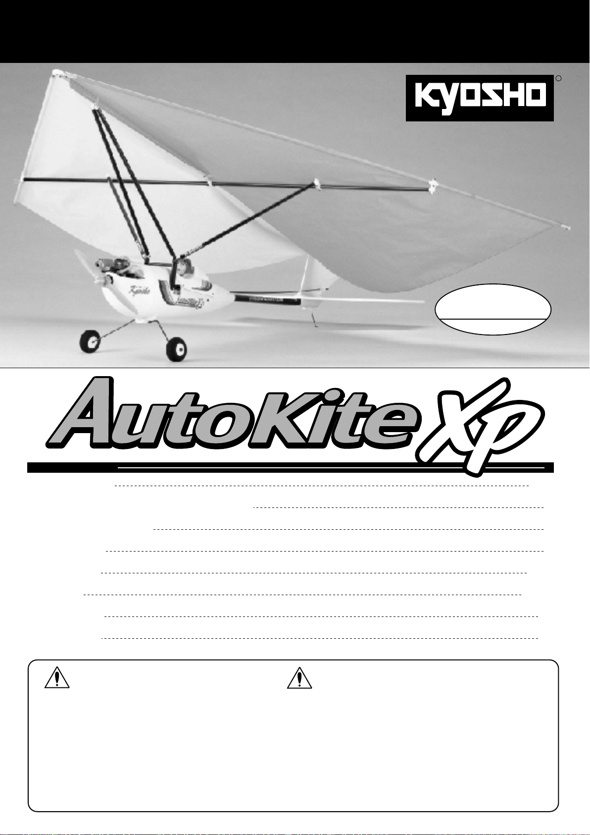
RADIO CONTROLLED .10 ENGINE POWERED AUTOKITE
目 次 INDEX
●組立て前の注意
BEFORE YOU BEGIN
●キットの他にそろえる物/組立てに必要な工具
REQUIRED FOR OPERATION / TOOLS REQUIRED
●キットに入っているもの
INCLUDED PARTS
●プロポの準備
RADIO PREPARATION
●本体の組立て
ASSEMBLY
●飛ばし方
How to Control the Kite
●パーツリスト
PARTS LIST
●取扱いの注意
OPERATING YOUR MODEL SAFELY
WIDTH: 1400mm (39.4")
オートカイトXP
2 / 4
2
3
4
5~22
23~25
25
28
安全のための注意事項
この無線操縦模型は玩具ではありません!
●この商品は高い性能を発揮するように設計されています。
組立てに不慣れな方は、模型を良く知っている人にアド
バイスを受け確実に組立ててください。
●小さい部品があるので、組立て作業は、幼児の手がとど
かない所で必ず行ってください。
●飛行して楽しむ場所は万一の事故を考えて、安全を確認
してから責任をもってお楽しみください。
●組立てた後も、説明書がいつでも見られるように大切に
保管してください。
※製品改良のため、予告なく仕様を変更する場合があります。
© 2002 KYOSHO CORPORATION/禁無断転載複製
*SPECIFICATIONS ARE SUBJECT TO BE CHANGED WITHOUT NOTICE.
UNDER SAFETY PRECAUTIONS
This radio control model is not a toy!
●First-time builders should seek the advice of experienced modelers
before beginning assembly.
●Assemble this kit only in places out of childrenÕs reach!
●Take enough safety precautions prior to operating this model.
You are responsible for this modelÕs assembly and safe operation!
●Always keep this instruction manual ready at hand for quick
reference, even after completing the assembly.
No.11111
組立て前の注意
組立てる前に説明書を良く読んで、おおよその構造を理解してから組立てに入ってください。
Read through the manual before you begin, so you will have an overall idea of what to do.
キットの内容をお確かめください。万一不良、不足がありましたら、お買い求めの販売店にご相談いただくか、当社「ユーザー相談室」までご連絡ください。
Check all parts. If you find any defective or missing parts, contact your local dealer or our Kyosho Distributor.
BEFORE YOU BEGIN
無線操縦飛行機が初めてという方は、調整等を経験者
Warning!
無線操縦飛行機が初めてという方には、単独飛行はできませんので、必ず経
験者の指導を受けてください。
この機体は、2サイクルの.10〜.15エンジン用に設計されていますのでこれ以
上のエンジンを使用し、過激な飛行をおこなうと破損するだけでなく、大変
危険ですので絶対におやめください。
完璧に完成したように見えても、組立ての状況によっては内部に接着不良の
ある場合があります。飛行中にわずかでも異常を感じたらただちに着陸させ、
原因を解明し、安全飛行につとめてください。
キットの他にそろえる物
のアドバイスを受けながら確実に組立ててください。
中途半端な組上がりの機体を飛ばすのは大変危険です。
(別購入品)
下記商品のメーカー、サイズ等は、販売店とご相談ください。
CAUTION: For details concerning the equipment listed below
注意
(size, maker, etc.), check with your hobby shop.
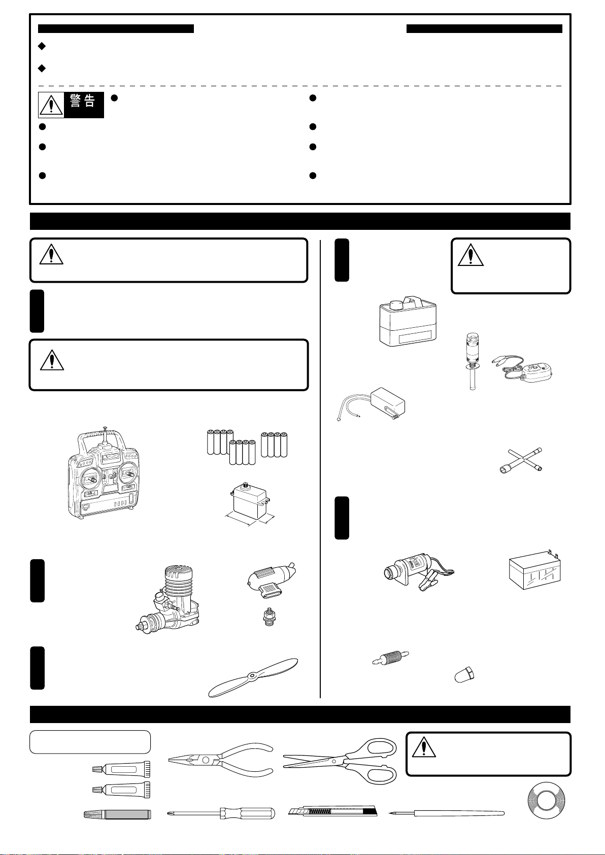
4チャンネル以上の飛行機用無線操縦機(プロポ)セット
1
(標準サーボx3)と乾電池。
A Minimum 4 channel radio for
and AA-size batteries.
aircraft
(with 3 servos),
空用(飛行機用)のプロポセット(4チャンネル以上)を必
ず使用してください。(空用以外使用禁止)
警告
CAUTION: Only use a minimum 4 channel transmitter, configured
for aircraft!
■飛行機用4チャンネル以上のプロポ
Minimum 4-channel radio.
(No other radio may be used!)
■単3乾電池x12本(送受信機用)
AA-size Batteries
(For Transmitter, Receiver)
AAAA
AAAA
■
サーボ
Servo
First-time fliers should seek advice for hints in pre-flight adjustments and
assembly from experienced fliers. Be reminded that flying a badly assembled
or badly adjusted aircraft is very dangerous!
In the beginning, first-time fliers should always be assisted by an experienced
flier and never fly alone!
This aircraft is designed for 2-stroke .10~.15 sized engines only. Using larger,
more powerful engens is not safe and may result in airframe failure.Do not exceed
the recommended engine size or engage in extreme aerobatic maneuvers.
Glue joints can loosen even thoogh they appear to be tight. If you notice
irregular flight, investigate the cause and repair it befor the next flight.
REQUIRED FOR OPERATION
燃料、始動用具
Required for engine starting
4
■模型用グロー燃料
Glow Fuel
Glow Fuel
el eng
d
o
m
■燃料ポンプ
Fuel Pump
No. 80701 燃料ポンプ(電動12V)
●
AAAA
FuelPump(Electric12V)
No. 80702 燃料ポンプ(手動)
●
FuelPump(Manual)
(Purchase separately!)
ガソリンや灯油は
使用禁止
WARNING: Gasoline
警告
or kerosene cannot
be used!
■プラグヒート
Plug Heater
el
u
e f
in
●No. 695143
スパークブースター
●No. 695142
DC急速充電器
■プラグレンチ
Plug Wrench
プロポの取扱いは、プロポに付属の説明書を
参考にしてください。
For proper radio operation, refer to its manual.
エンジン及びマフラー
2
Engine and Muffler
■飛行機用エンジン
Model Aircraft Engine
2サイクル .10〜.15
2-stroke .10~.15
プロペラ
Propeller
3
*ご使用になるエンジンに合った
サイズをお買い求めください。
Purchase a propeller that will match your engine.
組立に必要な工具
用意する工具
TOOLS NOT INCLUDED
■エポキシ接着剤
Epoxy Glue
■瞬間接着剤
Instant Glue
Epoxy A
Epoxy B
■ラジオペンチ
■+ドライバー(大、中、小)
38~41mm
■マフラー
Muffler
■プラグ
Glow Plug
■プロペラ
Propeller
(別購入品) TOOLS REQUIRED (Purchase separately!)
Needle Nose Pliers
Phillips Screwdriver (L.M.S)
16~20mm
■ハサミ
Scissors
■カッターナイフ
Sharp Hobby Knife
さらに用意すると良いもの
5
Useful Additional Equipment
■
エンジン始動用スターター
Engine Starter
●No. 1791
ブリッツスターター
Blitz Starter
■燃料フィルター
Fuel Filter
●No. 39308
燃料フィルター
Fuel Filter
注意
■キリ
Awl
■スターター用12Vバッテリー
12V Battery
●No. 71481
シールドバッテリー
Sealed Battery
●No. 90427-05
スピンナーナット
Spinner Nut
●No. 90901
パイロット人形
Pilot Figure
使用する工具の取扱いには、
十分注意してください。
CAUTION: Handle tools carefully!
■ビニールテープ
Tape
2
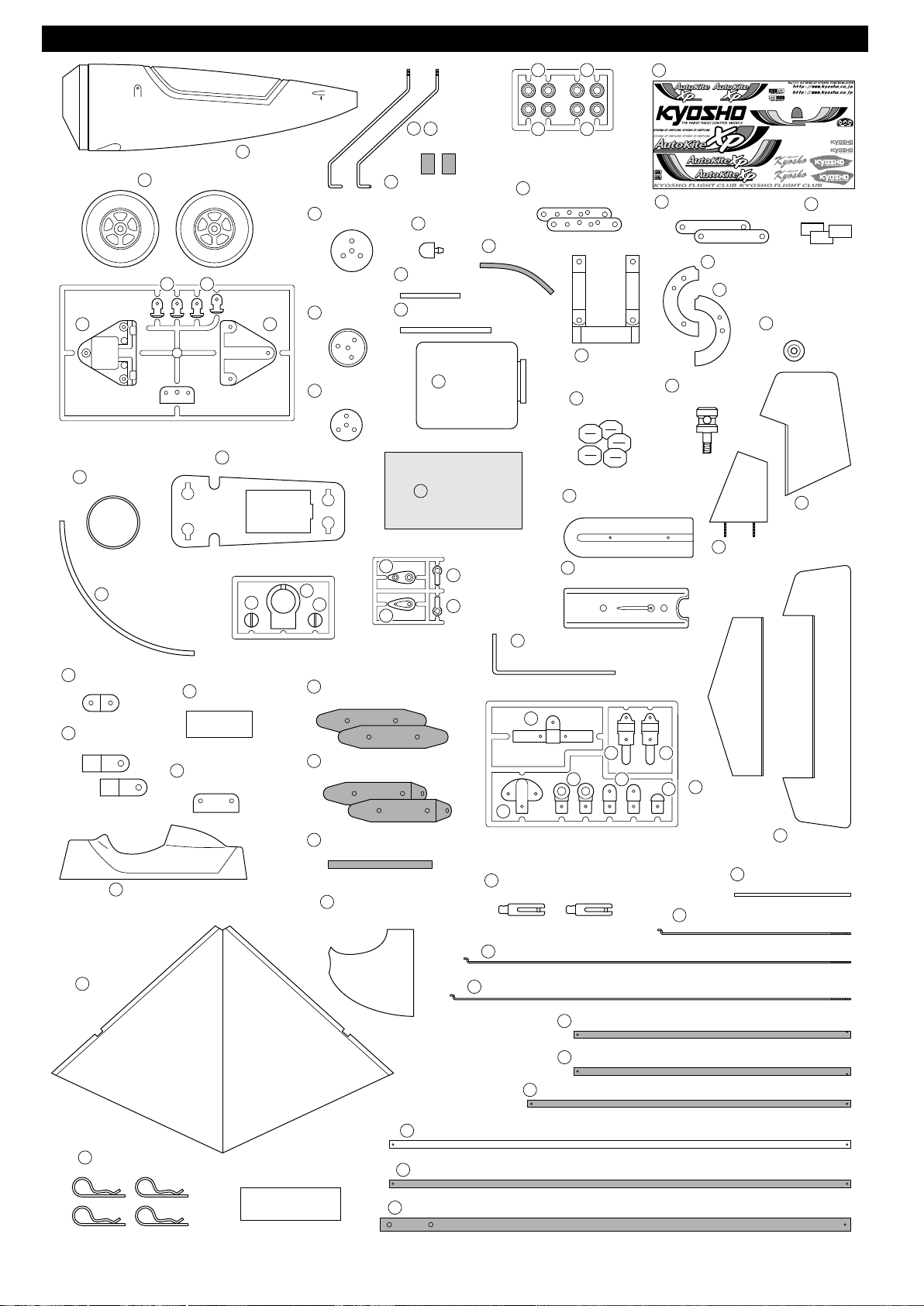
キットに入っているもの
INCLUDED PARTS
1
タイヤ
5
Tire
28
28
6 7
プラパーツ
Plastic Parts
24
サーボマウント
輪ゴム
27
Rubber Band
Servo Mount
胴体
Fuselage
アルミプレート
8
Aluminum Plate
ゴムブッシュ
9
Rubber Bushing
アルミプレート
10
Aluminum
2
3
メインギヤ取付カラー
4
Collar for Main Gear
オモリ
14
Weight
11
アルミパイプ(短)
Aluminum Pipe (Short)
アルミパイプ(長)
12
Aluminum Pipe (Long)
15
Plate
スポンジ
32
Sponge
メインギヤ
Main Gear
燃料タンク
Fuel Tank
ゴムブッシュ
Rubber Bushing
16
シリコンチューブ
13
Silicone Tube
1919
1919
エンジンマウントプレート(A)
Engine Mount Plate (A)
エンジンマウント
18
Engine Mount
ヒンジ
107
Hinges
尾翼取付プラパーツ
39
Plastic Part (Tail)
デカール
110
エンジンマウントプレート(B)
17
Engine Mount Plate (B)
103
Decal
エンジンマウント取付リング(A)
21
Engine Mount Guide (A)
エンジンマウント取付リング(B)
22
Engine Mount Guide (B)
リンケージガイド
Linkage Guide
2mm丸ナット
104
2mm Nut
100
カラー
20
Collar
ラダー
Rudder
シリコンチューブ
23
Silicone Tube
クランクアルミ板
65
Aluminum Crank
ジョイントアルミ
66
Joint Aluminum
50
セール
108
Sail
74
コックピット
Cockpit
41
プラパーツ
Plastic Parts
両面テープ
26
Double-sided Tape
メインギヤ取付金具
Metal Parts for Main Gear
25
41
パイプ取付金具(A)(黒)
94
Metal Parts (A) Black
パイプ取付金具(B)(黒)
95
Metal Parts (B) Black
5mmジョイント(黒)
96
Joint 5mm (Black)
カウリング
105
Cowling
36
35
プラパーツ
Plastic Parts
37
37
テールスキッド
43
Tail Skid
58
62
ロッドアジャスター
47
Rod Adjuster
リンケージロッド(520mm)
80
リンケージロッド(540mm)
81
尾翼取付プラパーツ
40
Plastic Part (Tail)
64
5961
プラパーツ
Plastic Parts
Linkage Rod (540mm)
垂直尾翼
99
Vertical Tail
63
水平尾翼
97
60
Horizontal Tail
102
エンコンロッド(1.2mm)250mm
101
Throttle Rod (1.2mm) 250mm
Linkage Rod (520mm)
エレベーター
98
Elevator
PPパイプ (150mm)
PP Pipe (150mm)
フックピン
84
Hook Pin
ビス類
Screw
スパー(500mm )
53
スパー(黒)(500mm )
90
テールパイプ
109
91
Spur 500mm
Spur (Black) 500mm
(黒)(510mm )
サイドバー(L)(黒)300mm
92
サイドバー(R)(黒)300mm
93
フロントバー(黒)350mm
Tail Pipe (Black) 510mm
Side Bar (L) (Black) 300mm
Side Bar (R) (Black) 300mm
Front Bar (Black) 350mm
3
組立て前の注意
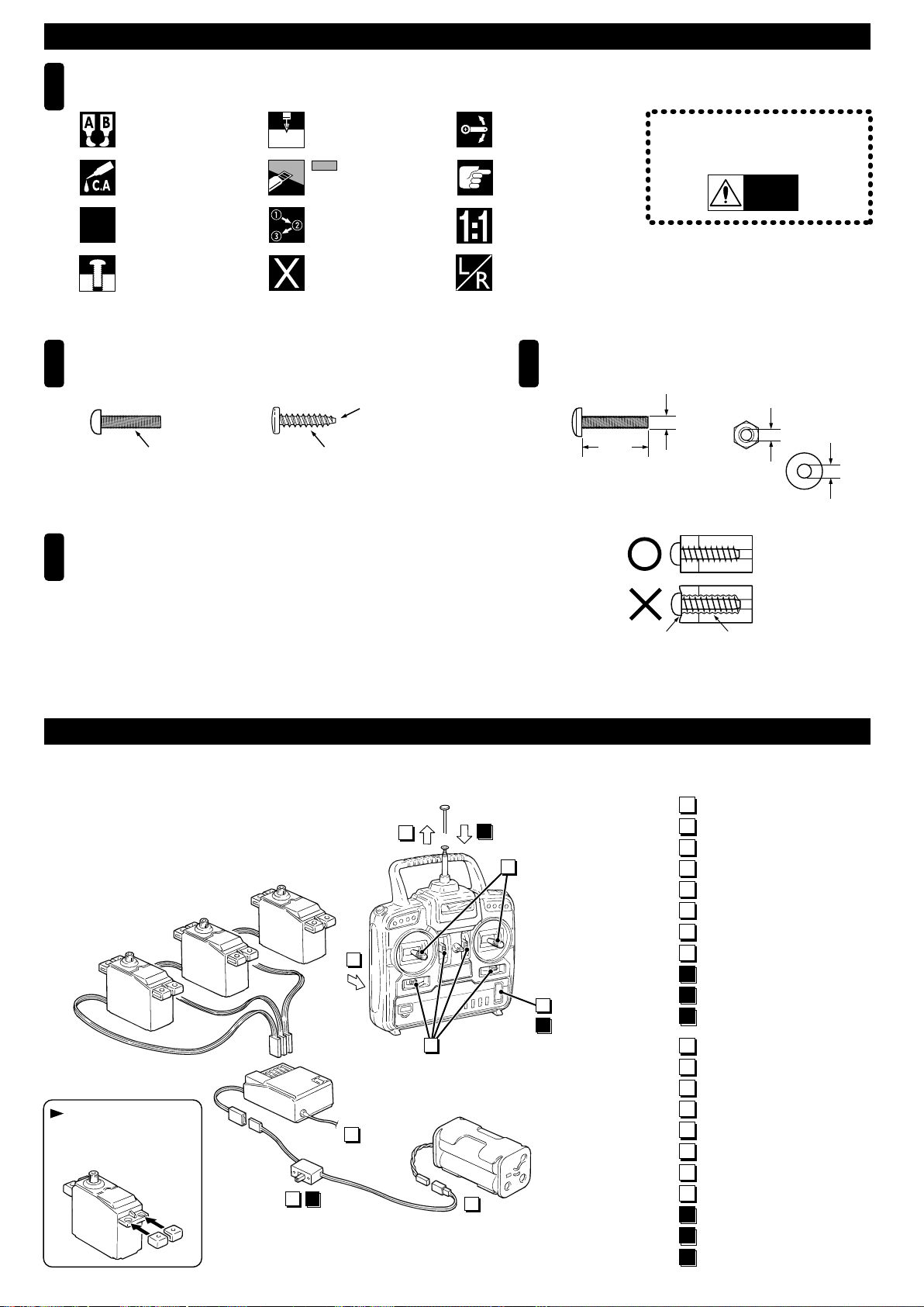
説明書に使われているマーク
1
Symbols used throughout this instruction manual, comprise:
BEFORE YOU BEGIN
エポキシ接着剤で接着する。
Apply epoxy glue.
瞬間接着剤で接着する。
Apply instant glue
(CA glue, super glue).
2セット組立てる(例)。
Assemble as many times
x2
as specified.
仮止め。
Tentatively tighten.
ビス類の見分け方
2 3
How to understand the figures.
●ふつうのビス
Ordinary Screw
ネジ山がこまかい
Finer Thread
TPビスは、部品にネジを切りながらしめつけるビスです。しめこみがかたい場合が
4
ありますが、確実に部品が固定されるまでしめこんでください。ただししめすぎる
とネジがきかなくなりますので、部品が変形するまでしめないでください。
Excessive force may permanently damage parts when tightening self-tapping screws.
It is recommended to stop tightening when some resistance is felt after the threaded
portion enters the plastic.
●TPビス
2mmの穴をあける(例)。
Drill holes with the specified
diameter (here: 2mm).
2mm
をカットする。
Cut off shaded portion.
番号の順に組立てる。
Assemble in the
specified order.
別購入品
Must be purchased
separately!
TP Screw
ネジ山があらい
Coarser Thread
可動するように組立てる。
Ensure smooth non-binding
movement while assembling.
注意して組立てる所。
Pay close attention here!
原寸図。
True-to-scale diagram.
左右同じように組立てる。
Assemble left and right sides
the same way.
先のほそいものもある
Some of them have
pointed tips.
ビス類のサイズの表し方
Sizes of screws.
■ビス3×15
Screw
15mm
Right
Wrong
しめすぎ
Over-tightened
●重要な注意事項があるマークです。
必ずお読みください。
Do not overlook this symbol!
警告
Warning!
■ナット・ワッシャー3mm
Nut and Washer
3mm
3mm
3mm
ビスがきかない
The threads are stripped
プロポの準備
プロポを下の順序にしたがってセットします。
Set up the radio as explained below.
▼サーボ
Servo
サーボにグロメットを
取り付けておく。
Install the grommets to
the servo as shown.
7 9
4
1
受信機
▲
Receiver
4
RADIO PREPARATION
2
5
11
3
8
送信機
▲
Transmitter
6
10
▲
バッテリー
Battery
ON
OFF
●始める時
●終わる時
START
FINISH
1
単3乾電池をセットする。(送信機)
2
アンテナをのばす。(送信機)
3
コネクターをつなぐ。
4
アンテナをのばす。(受信機)
5
トリムレバーを中央にセットする。
6
スイッチを入れる。(送信機)
7
スイッチを入れる。(受信機)
8
スティックを動かしてサーボが動くか確認する。
9
スイッチを切る。(受信機)
10
スイッチを切る。(送信機)
11
アンテナを縮める。(送信機)
1
Install AA-size batteries. (Transmitter)
2
Extend the antenna. (Transmitter)
3
Connect the battery.
4
Extend the antenna. (Receiver)
5
Center the trims.
6
Switch on. (Transmitter)
7
Switch on. (Receiver)
8
Make sure the servos are in command.
9
Switch off. (Receiver)
10
Switch off. (Transmitter)
11
Retract the antenna. (Transmitter)
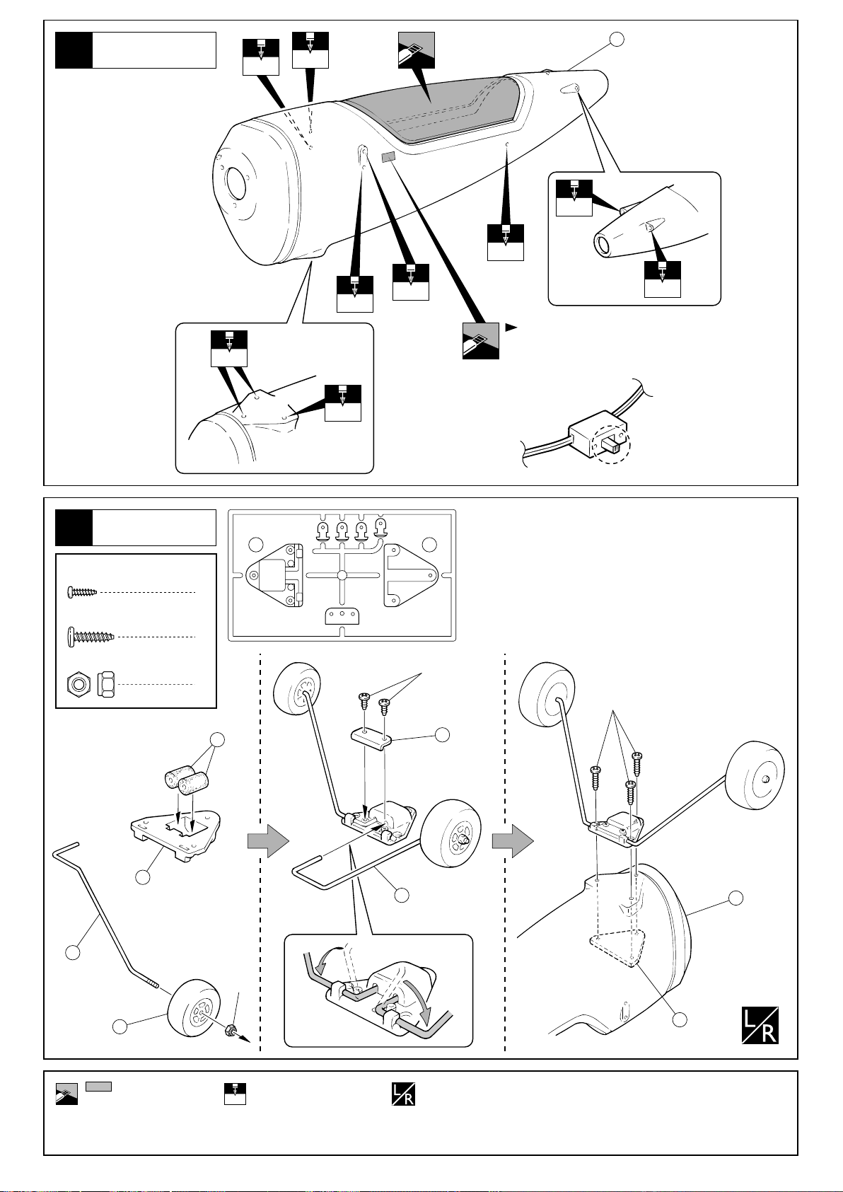
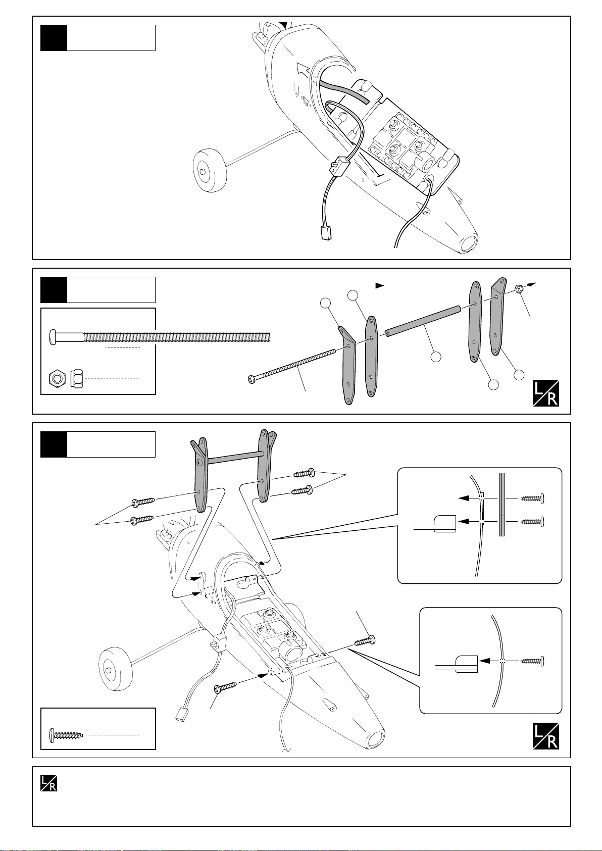
1
胴体
Fuselage
3mm
1
2mm
3mm
3mm
メインギヤ
Main Landing Gear
2
2 x 6mm
TP Screw
2.6 x 10mm
TP Screw
3mm
Nylon Nut
TPビス
TPビス
ナイロンナット
2
3
2
3mm
3mm
3mm
6 7
2mm
3mm
受信機用スイッチの大きさ
に合わせてカット。
Cut off to fit the switch siza.
2x6mm
2.6x10mm
2
5
をカットする。
Cut off shaded portion.
4
6
3mm
3mmの穴をあける(例)。
Drill holes with the specified diameter.
3mm
74
3
左右同じように組立てる。
Assemble left and right sides
the same way.
1
7
重要な注意事項があるマークです。
必ずお読みください。
Do not overlook this symbol!
Warning!
5
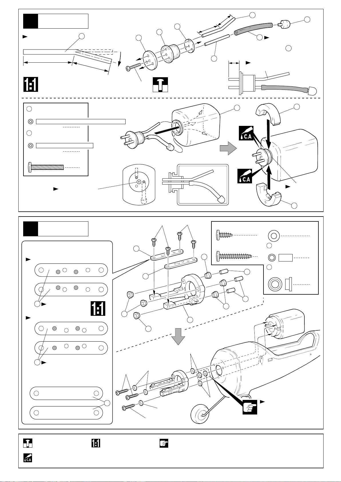
燃料タンク
Fuel Tank
3
図の様に曲げる。
Bend as shown.
長い
Long
12
短い
Short
8
3x20mm
10
長い
Long
短い
Short
12
14
9
13
シリコンチューブ
47mmにカット
Cut the Silicone Tube
13
11
12mm
向きに注意。
Note the direction.
to 47mm Length.
12
アルミパイプ(長)
Aluminium Pipe (Long)
1
11
アルミパイプ(短)
Aluminium Pipe (Short)
3 x 20mm
Screw
ビス
タンクに入れた後、
3x20mmをしめる。
Tighten the 3 x 20mm
screw carefully.
1
1
燃料タンク
Fuel Tank
4
< >
OS製エンジンを使用する場合
< >
For OS engine
OS Max-10LA
前
Front
< >前から見た図
< >Front View
16
16
3x8mm
3x8mm
3 x 8mm
TP Screw
3 x 20mm
TP Screw
19
15
TPビス
TPビス
20
3mm
Washer
4
20
カラー
Collar
3
19
ゴムブッシュ
Rubber Bushing
21
ミゾにはめる。
Fit 21 into
the groove.
22
ワッシャー
7
3
6
16
向きに注意。
Note the direction.
OS Max-15LA
前
Front
16
向きに注意。
Note the direction.
< >
京商製・OS製以外のエンジンを使用する場合
< >For others
前
Front
仮止め。
Tentatively tighten.
瞬間接着剤で接着する。
Apply instant glue
(CA glue, super glue).
原寸図。
True-to-scale diagram.
17
19
3x20mm
19
3mm
3x20mm
3mm
注意して組立てる所。
Pay close attention here!
18
3mm
3mm
19
20
ここだけ2枚入れる。
Install two washers only
for only this hole.
重要な注意事項があるマークです。
必ずお読みください。
Do not overlook this symbol!
Warning!
6
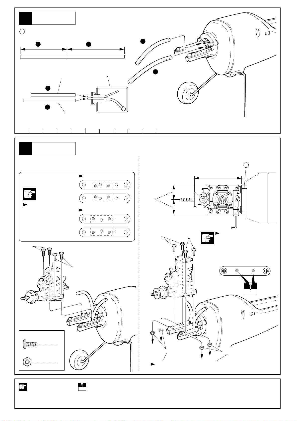
燃料タンク
Fuel Tank
5
23
シリコンチューブ
Silicone Tube
80mm 90mmA
B
A
マフラープレッシャーへ
Muffler Pressure
燃料タンク
Fuel Tank
B
A
B
キャブレターへ
Carburetor
50 100
エンジン
Engine
6
< >OS製エンジン < >
OS製以外のエンジン
< >For OS Engine < >For others
< >上から見た図
< >Top View
3x8mm
3x8mm
取付け穴注意。
Ensure that you use
the correct holes.
3x8mm
前
Front
前
Front
OS Max-10LA
平行
Parallel
OS Max-15LA
3x8mm
約73mm
18
approx. 73mm
O.S.製以外のエンジンを使用
するときは、上図を参考に穴
加工(3mm)してください。
When using engines from other
manufacturers than OS, refer
to the diagram for making
3mm holes.
3 x 8mm
Screw
3mm
Nut
ビス
ナット
注意して組立てる所。
Pay close attention here!
3mm
4
3mm
4
3mmの穴をあける(例)。
Drill holes with the
3mm
specified diameter.
O.S.製以外のエンジンのときに使う。
Use 3mm nuts with engines other than from OS.
3mm
重要な注意事項があるマークです。
必ずお読みください。
Do not overlook this symbol!
Warning!
7
サーボマウント
Servo Mounts
7
282528
28
28
25
24
8
サーボ
Servo
Supplied with the servo.
エレベーターサーボ
Elevator Control Servo
ラダーサーボ
Rudder Control Servo
スロットルサーボ
Throttle Control Servo
両面テープ
Double-sided Tape
サーボ付属
26
受信機
Receiver
サーボ付属
Supplied with
the servo.
アンテナコード
Antenna Cord
アンテナコード
を通す。
Antenna code should come
through the round hole.
1.5
mm
スイッチ
1.5
8
サーボ
Servo
9
プロポの説明書を参考に、
コネクターを接続する。
Connect as per radio
instruction manual.
Switch
エポキシ接着剤で接着する。
Apply epoxy glue.
1.5mmの穴をあける(例)。
Drill holes with the
mm
specified diameter.
注意して組立てる所。
Pay close attention here!
別購入品。
Must be purchased separately!
コードを輪ゴムで束ねる。
Bind the wires with Rubber Band.
27
輪ゴム
Rubber Band
重要な注意事項があるマークです。
必ずお読みください。
Do not overlook this symbol!
Warning!
10
サーボ
Servo
胴体
Fuselage
11
3 x 75mm
Screw
3mm
Nylon Nut
12
2.6x10mm
ビス
ナイロンナット
胴体
Fuselage
向きに注意。
94
95
1
1
3x75mm
2.6x10mm
Note the direction.
3mm
96
95
94
2.6 x 10mm
TP Screw
左右同じように組立てる。
Assemble left and right sides
the same way.
TPビス
2.6x10mm
2.6x10mm
6
9

スイッチ
Switch
13
2mm
スイッチに合わせ
2mmの穴をあける。
Drill 2mm holes to where
the switch holes located.
スイッチ
Switch
スイッチに
付属のプレート
Included with
the switch.
スイッチに付属のビス
Included with the switch.
垂直/水平尾翼
Vertical / Horizontal Tail
14
107
向きに注意。
Note the direction.
97
98
107
100
10
向きに注意。
Note the direction.
2mmの穴をあける(例)。
Drill holes with the
2mm
specified diameter.
107
別購入品。
Must be purchased separately!
107
99
重要な注意事項があるマークです。
必ずお読みください。
Do not overlook this symbol!
Warning!

垂直/水平尾翼
Vertical / Horizontal Tail
15
低粘度瞬間接着剤がヒンジにし
みこむ様にして確実に接着する。
Install the hinges completely
before applying instant glue.
低粘度瞬間接着剤がヒンジにし
みこむ様にして確実に接着する。
Install the hinges completely
before applying instant glue.
Warning!
確実に接着する。
飛行中にはずれると操縦不能になり事故につながります。
Securely glue together. If it comes off during flights, you
may lose control of your airplane, resulting in an accident !
垂直/水平尾翼
Vertical / Horizontal Tail
16
フイルムのみ。
Only cut the film.
Do not cut into
the wood.
3mm
2 x 10mm
TP Screw
2.6 x 25mm
Screw
フイルムのみ。
Only cut the film.
Do not cut into
the wood.
TPビス
ビス
6mm
19mm
8mm
35
37
2.6x25mm
2x10mm
35
37
37
36
37
36
8mm
2mm
6mm
10mm
37
2
2
35
37
37
35
36
3mm 2mm
37
36
25mm
可動するように組立てる。 瞬間接着剤で接着する。
Ensure smooth, non-binding
movement when assembling.
2mmの穴をあける(例)。
Drill holes with the
2mm
specified diameter.
Apply instant glue
(CA glue, super glue).
2x10mm
2.6x25mm
をカットする。
Cut off shaded portion.
10mm
重要な注意事項があるマークです。
必ずお読みください。
Do not overlook this symbol!
Warning!
11

垂直/水平尾翼
Vertical / Horizontal Tail
17
40
41 41
43
39
109
41
垂直/水平尾翼
Vertical / Horizontal Tail
18
2.6 x 10mm
TP Screw
TPビス
41
1
2
を締め込んだ後で曲げる。
41
Tighten and bend the
rod as shown.
1
41
2.6x10mm
番号の順に組立てる。
Assemble in the specified order.
12
エポキシ接着剤で接着する。
Apply epoxy glue.
重要な注意事項があるマークです。
必ずお読みください。
Do not overlook this symbol!
Warning!

90¡
90¡
90¡
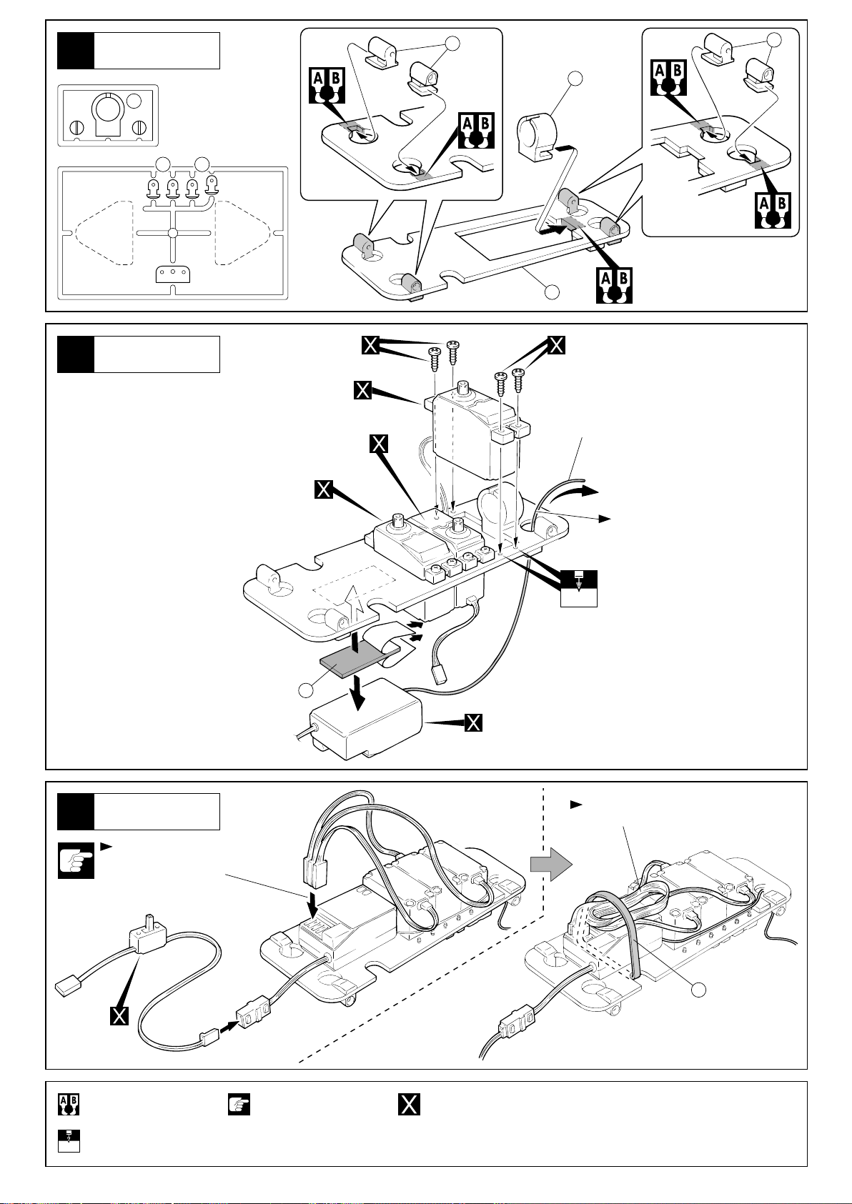
リンケージ
Linkage
19
103 104
Linkage Guide
1
2mm
ワッシャー
Washer
3
2mm
丸ナットリンケージガイド
Nut
番号の順にチェックし、必ずニュートラル
2
1
位置で組み立ててください。
Electronically center the servos and
proceed the following step.
x3
7~8mm
103
2mm
104
垂直/水平尾翼
Vertical / Horizontal Tail
20
80
81
540mm
520mm
3
サーボ付属のビス
Supplied with
the servo.
ON
4
ON
サーボ付属のビス
2
Supplied with
the servo.
1
80
1
2
2
前
Front
81
1
2
1
47
2
3
90ûになるように、 の
ねじ込み量を調整する。
Adjust so the rudder
47
and the elevators are at
right angles when rudder
servo is in neutral.
1
47
ニュートラル位置
Neutral
3
47
90û
4747
90û
2
90ûになるように、 の
ねじ込み量を調整する。
Adjust so the rudder
and the elevators are at
right angles when rudder
servo is in neutral.
47
47
をカットする。
Cut off shaded portion.
別購入品。
Must be purchased separately!
注意して組立てる所。
Pay close attention here!
番号の順に組立てる。
Assemble in the specified order.
3セット組立てる(例)。
Assemble as many times as specified.
x3
可動するように組立てる。
Ensure smooth, non-binding
movement when assembling.
重要な注意事項があるマークです。
必ずお読みください。
Do not overlook this symbol!
Warning!
13

21
バッテリー
Battery
27
輪ゴム
Rubber Band
スポンジ
Foam Pad
32
バッテリー
Battery
Warning!
確実に取り付ける。
飛行中にはずれると操縦不能になり事故につながります。
Securely glue together. If it comes off during flights, you
may lose control of your airplane, resulting in an accident !
スロットルリンケージ
Throttle Linkage
22
3 x 3mm
Set Screw
セットビス
< >ニュートラル
< >Neutral
1
1
< >スロー
< >Idle
2
102
5
102
エポキシ接着剤で接着する。
Apply epoxy glue.
4
3x3mm
2
101
< >ハイ
< >High
3
番号の順に組立てる。 別購入品。
Assemble in the specified order. Must be purchased separately!
重要な注意事項があるマークです。
必ずお読みください。
Do not overlook this symbol!
Warning!
14

23
24
カウリング
Cowling
105
マフラー
Muffler
Warning!
エンジン回転中にプロペラがはずれないように、
確実にビスをしめる。
回転中にはずれるとケガのおそれがあります。
Be sure to tighten the nut. If it comes off,
it can cause serious bodily harm and damage to property.
23
25
エンジン
Engine
シリコンチューブ
Silicone Tube
プロペラ
Propeller
23
シリコンチューブ
Silicone Tube
マフラー付属
Supplied with the Muffler.
燃料タンク
Fuel Tank
マフラープレッシャーへ
Muffler Pressure
キャブレターへ
Carburetor
別購入品。
Must be purchased separately!
重要な注意事項があるマークです。
必ずお読みください。
Do not overlook this symbol!
Warning!
15

26
胴体
Fuselage
1mm
50
1mm
1mm
胴体に合わせ1mmの穴をあける。
Trial fit the cockpit to the fuselage,
drill holes where the holes in the fuselage located.
コックピットのカットラインは大きめになっています。
50
胴体に合わせ少しづつカットしてください。
Carefully cut out the canopy to fit the fuselage.
胴体
Fuselage
27
2 x 6mm
TP Screw
28
TPビス
スパー
Spur
2x6mm
4
アンテナコードを通す。
Thread antenna cord through.
2x6mm
アンテナコード
Antenna Cord
2 x 6mm
TP Screw
TPビス
8
16
58
2x6mm
59
をカットする。
Cut off shaded portion.
注意して組立てる所。
Pay close attention here!
59
60
53
1mmの穴をあける(例)。
Drill holes with the
1mm
specified diameter.
2x6mm
500mm
58
58
2セット組立てる(例)。
Assemble as many times as specified.
x2
53
2x6mm
500mm
ここで使用するパイプは
銀パイプ。
53
Note :
Use Silver Spur in this step.
2x6mm
x2
重要な注意事項があるマークです。
必ずお読みください。
Do not overlook this symbol!
Warning!
60

29
スパー
Spur
108
710mm
テープを2回巻く。
Bind by Tape.
スパー
Spur
スパー
Spur
30
2 x 6mm
TP Screw
TPビス
58
62
4
向きに注意。
Note the direction.
6
2x6mm
60
2x6mm
62
53
ここで使用するパイプは
銀パイプ。
53
Note :
Use Silver Spur in this step.
500mm
53
2x6mm
500mm
テープを2回巻く。
Bind by Tape.
60
20mm
2
110mm
注意して組立てる所。
Pay close attention here!
1
テープを2回巻く。
Bind by Tape.
番号の順に組立てる。 別購入品。
Assemble in the specified order. Must be purchased separately!
3
58
平らな面が上。
Flat spot faces top.
2x6mm
重要な注意事項があるマークです。
必ずお読みください。
Do not overlook this symbol!
Warning!
17

クロスバー
Cross Bar
31
58
61
2 x 6mm
TP Screw
TPビス
2x6mm
61
61
穴がななめな面が下。 穴がななめな面が下。平らな面が下。
Side with wider hole
faces bottom.
2x6mm
240mm
テープを2回巻く。
Bind by Tape.
Flat spot faces bottom.
2x6mm
Side with wider hole
faces bottom.
2x6mm
90
240mm
500mm
テープを2回巻く。
Bind by Tape.
58
4
500mm
90
ここで使用するパイプは 黒パイプ。
Note : Use Black Spur in this step.
90
クロスバー
Cross Bar
32
1
2x6mm
2 x 6mm
TP Screw
84
TPビス
フックピン
Hook Pin
63
6
2
64
約710mm
approx. 710mm
6364
84
5
2x6mm
クロスバー
Cross Bar
このビスはいっぱいに
締めてから半回転もどす。
Tighten the screw once,
and unscrew 180 degree.
2
64
84
5
2x6mm
4
65
63
2x6mm
2x6mm
約710mm
approx. 710mm
3
フロントバー
Front Bar
33
平らな面が下。
Flat spot faces bottom.
59
2 x 6mm
TP Screw
2.6 x 6mm
TP Screw
注意して組立てる所。
Pay close attention here!
別購入品。
Must be purchased separately!
18
TPビス
TPビス
2x6mm
91
ここで使用するパイプは
黒パイプ。
91
Note :
Use Black Spur in this step.
2x6mm
向きに注意。
Note the direction.
2.6x6mm2.6x6mm
59
350mm
x2
4
2
番号の順に組立てる。
Assemble in the specified order.
2.6x6mm
2セット組立てる(例)。
Assemble as many times as specified.
x2
2.6x6mm
59
重要な注意事項があるマークです。
必ずお読みください。
Do not overlook this symbol!
Warning!

サイドパー
Side Bar
34
A
右側用
For right side.
向きに注意。
Note the direction.
300mm
2x6mm
ここで使用するパイプは
黒パイプ。
92
93
Note :
Use Black Spur in this step.
61
A
B
59
B
左側用
For left side.
向きに注意。
Note the direction.
59
61
2x6mm
59
92
2x6mm
2x6mm
300mm
93
穴がななめな面が下。
Side with wider hole
faces bottom.
2 x 6mm
TP Screw
2.6 x 6mm
TP Screw
TPビス
TPビス
A
B
2.6x6mm
61
向きに注意。
Note the direction.
2.6x6mm
A
4
2
B
2.6x6mm2.6x6mm
クロスバー
Cross bar
35
2 x 6mm
TP Screw
TPビス
2x6mm
63
63
66
4
240mm
20mm
2x6mm
63
63
240mm
6364
110mm
66
注意して組立てる所。
Pay close attention here!
仮止め。
Tentatively tighten.
重要な注意事項があるマークです。
必ずお読みください。
Do not overlook this symbol!
Warning!
19

36
セール取付
Sails
向きに注意。
Note the direction.
1
2.6 x 12mm
TP Screw
3 x 12mm
Screw
TPビス
1
ビス
1
84
2.6x12mm
4
2
2.6x12mm
仮止めしてあるビスを本締めします。
Tighten the screws.
240mm
2
84
3mm
3mm
Nylon Nut
84
3
3x12mm
Warning!
確実に取り付ける。
飛行中にはずれると操縦不能になり
事故につながります。
Securely glue together. If it comes off
during flights, you may lose control of
your airplane, resulting in an accident !
ナイロンナット
1
フックピン
Hook Pin
2
37
デカール
Decals
図を参考にデカールをはる。
Apply decals as illustrated.
アンテナ
Antenna
アンテナをデカールの
あまりではる。
Apply extra part of decals.
番号の順に組立てる。
Assemble in the specified order.
20
重要な注意事項があるマークです。
必ずお読みください。
Do not overlook this symbol!
Warning!

重心位置
C of G position
38
Warning!
重心のチェックをする前に飛行は、おこなわない。
重心位置が正しくないと操縦不能になり事故につながります。
Do not fly before confirming the correct location of the CG.
If the CG is incorrect, you lose control of your airplane which
leads to accidents!
< >上から見た図
< >Top View
430~450mm
重心位置
CG
完成図
Completed Kite
39
機体がかたむく場合は、バッテリーを前後に
移動し、重心位置を合わせる。
If necessary, re-position battery to get correct C of G.
バッテリー
Battery
注意して組立てる所。
Pay close attention here!
重要な注意事項があるマークです。
必ずお読みください。
Do not overlook this symbol!
Warning!
21

蛇角調整
Adjustment
図の様に各舵が動くように調整する。図の動作量は通常の飛行に適した舵角です。
Adjust the travel of each control surface to the values in the diagrams.
< >エレベーター
< >Elevator
ダウン
Down
アップ
Up
< >横から見た図
< >Side View
アップ
Up
ダウン
Down
ダウン
Down
アップ
Up
測定位置
Position for
left diagram.
8mm
8mm
< >ラダー
< >Rudder
左 右
Left Right
< >上から見た図
< >Top View
左
Left
左
Left
30mm 30mm
右
Right
右
Right
測定位置
Position for left diagram.
< >スロットルコントロール
< >Throttle Control
ハイ
High
ハイ(全開)スロー
Full ThrottleLow Throttle
スロー
Slow
無線操縦飛行機が初めてという方は、調整及び飛ばし方を、経験者のアドバイスを受けながら行ってください。
If you are a beginner, do not fly alone. Find a local R/C club or an experienced R/C flier.
飛行不可
Flying impossible.
飛行要注意
Limit
飛行可能
Flying possible.
エンジンスロー
Engine control slow.
指を放す。
Do not move any stick.
エンジンハイ
Engine control high.
エンジンスロー
Engine control slow.
本機は、基本的にエレベーターがニュートラルの時、スロットルコントロール
のみで上昇するように設計されております。初飛行の際に機体が急上昇もしく
は急下降する場合は、スロットルコントロールのみで上昇、下降ができるよう
にエレベータートリムを正しく調整してください。
Note: The Autokite XP uses the throttle only to climb and descend.
Adjust the elevator trim so that the kite flies level at approximately
1/2 to 3/4 throttle.
本機は、飛行速度が遅いので、風が強いと風上へ進みにくくなりますので、
送信機のアンテナにリボンなどを付け、リボンの傾きを参考に、飛行可能か
決めてください。
Because the flying speed of the AUTOKITE XP is relatively slow, flying it
windward will reduce its speed even more. Use the ribbon attached to the
transmitter antenna as a vane and watch out for it in order to judge by
yourself whether the present velocity allows flights or not.
飛行中、機体の姿勢がわからなくなったり、又は操縦ミスで墜落しそうに
なったら、すぐにエンジンスローにし、同時にラダー、エレベーターから
手をはなしてください。高度が10m以上あればすぐに水平飛行にもどります。
In case you should not be able to recognize the kite's position anymore
because it is flying too far away, or in case the kite is likely to crash due to a
control error, reduce engine power and, at the same time, do not manipulate
the rudder and elevator. If such is the case and the AUTOKITE XP is flying at
an altitude of more than 10m, it will immediately return to horizontal position.
本機は、エンジンのパワーを上げても飛行スピードはあまりかわりません。
かわりにどんどん上昇していきます。飛行高度は、エンジンパワーを上手
にコントロールして上下させてください。
Even if increasing engine power, the AUTOKITE XP's flying speed will not
change much. Instead, if will gradually gain altitude. Therefore, use the
engine control stick for changing altitude.
22

< >離陸させるときは
< >Take-off From a Runway
1
平坦な地面を選び、機首を風上に向け、機体の真後ろに立って、スロットルスティックを少しずつ上げていく。
Take-off from a surface as smooth as possible; stand just behind the kite and gradually move the throttle control stick up.
2
スピードが十分についたら、エレベータースティックを少しずアップにすると離陸する。
When the kite gains speed, slowly move the elevator stick down.
3
離陸後、急上昇しないように、エレベータースティックを少しずつ戻す。
After the kite leaves the ground, gently return the elevator to neutral position.
少しずつエレベータースティックを
※
ニュートラルに戻す。
風
Wind
Gradually return
the stick.
3
飛ばし方(1)
少しエレベーターを
※
アップにする。
Gradually pull the
stick down.
How to Control the Kite (1
2
)
少しずつ上げていく※
Gradually pull the
throttle up.
1
< >手投げ発進の時は
< >Launching the kite by hand
1
機体の重心を持ち、風上に向ける。
Hold the kite firmly by the fuselage and as close to the center of gravity as possible.
2
スロットルスティックをハイにする。
Push the throttle stick up.
3
5〜6歩かけだし、機体を水平に押し出す。
Run a few steps and launch the kite with plenty of airspeed and as level as possible into the wind.
4
手投げ後、エレベータースティックを少しずアップにしていく。
Slowly pull the elevator stick down once the kite is launched.
5
機体が急上昇しないように、エレベータースティックを少しずつ戻す。
If the kite climbs too steeply, slowly return the elevator stick.
6
上昇中、左右どちらかに曲がるようであれば、ラダースティックを操作し、真直ぐになおす。
If the kite banks left or right, control with the rudder the direction you want the kite to go.
傾かないようにラダーを操作して調整※
6
風
Control with the rudder stick not to bank.
6
Wind
少しずつエレベータースティックをニュートラルに戻す。※
Gradually return the stick.
少しエレベーターをアップにする。※
Gradually pull the stick down.
5
5
4
4
3
1
2
23

飛ばし方(2)
< >旋回 ※ 右旋回の場合
< >Turning
1
ラダースティックを右に倒す。(1/3〜1/2位)
Move the rudder about 1/3 to 1/2 of stick travel right.
Right Turn
How to Control the Kite (2
)
1
2
機体が傾いたらラダースティックをもどす。
エレベータースティックは操作しなくてもよい。
As soon as the kite is in a tilted position, return the rudder
stick to neutral position. It is not necessary to control the
elevator when changing the kite's flight direction.
3
途中で水平にもどってしまったら、
1 2
, を繰り返す。
As soon as it returns to horizontal position when
performing turns, repeat steps and .
4
希望のところまで旋回したら、ラダースティックを
左へ倒し機体を水平にもどす。
AS soon as the kite finishes the turn, move the rudder
into the opposite direction of turn (in this case, move
it left) and bring the kite back to horizontal position.
慣れないうちは機体の傾きを小さくし、
大きく旋回させます。
Do not attemp to bank the kite too steeply
until you have gained more experience.
In the beginning make wide and slow turns.
1 2
1/3〜1/2位右に倒す※
1
Travel 1/3 to 1/2
to the right.
243
舵は少し遅れて反応しますので、早め早めの
操作が上手に飛ばすコツです。
Because the controls respond slowly, slightly
manipulate the sticks ahead of time!
< >着陸
< >Landing
1
機体を風下から風上に向けて、着陸体勢をとる。その時、大事なことは、右や左にそれないようラダーでコントロールする。
Land the kite windward while keeping it straight.
2
エンジンスローにして高度を下げる。
Reduce engine power for gradually decreasing the altitude.
3
着陸寸前(高度1m〜50cm位)から少しずつエレベーターを
アップにし、機首を上げて着陸させる。
Just before landing (altitude of 1m to 50cm), slowly lift the
elevator to raise the kite's nose, and land it.
少しずつエレベーターを
※
3
風
Wind
アップする
Gradually pull the stick up.
2
1
24
1
3
1m ~ 50cm
風上に向かったら、左右に傾かない
※
ようにラダーを操作して調整
Keep balance with rudder stick.

セールのたたみ方
How to fold the sale.
3
2
2
3
4
1
5
4
5
6
1
品番
No.
胴体
PA1
Fuselage
カウリング
PA2B
Cowling
尾翼プラパーツ
PA5
Tail Wing Plastic Parts
メカプレートセット
PA6B
Radio Plate
ジョイントプラパーツ
PA12B
Joint Plastic Parts
ジョイント金具パーツ
PA13B
Joint Metal Parts
テールパイプ
PA27B
Tail Pipe
セール
PA29B
Sail
ウイングパイプセット
PA30B
Wing Pipe Set
品番
No.
カラーシリコンチューブ
1790
Color Silicone Tube
燃料フィルター(M)
39308
Fuel Filter (M)
ナイロンプロペラD8xP4
90408-04
Nylon Propeller D8xP4
90427-05
スピンナーナット(M5)
Spinner Nut (M5)
パーツ名
Part Names
パーツ名
Part Names
スペアパーツ
内容(キーNo.と入数)
Quantity
1 x 1
105
x 1
25
39 40 43
24 26 27 32
58 60 62 63 64
61
x 259x 3
65 66 94 95
x 1 x 2
109
x 1
108
x 1
92 93
90 91
x 1
x 2
x 141x 2
x 1
x 1
53
x 6
オプションパーツ
内容(キーNo.と入数)
Quantity
シリコンチューブ(赤, 青)
Silicone Tube (Red, Blue)
燃料フィルター
Fuel Filter
x 1
スピンナーナット, ナット, レンチ
Spinner Nut, Nut, Wrench
x 1
x 1
★定価
1200
700
500
550
400
900
1200
5500
4200
★定価
400
1000
750
700
★発送
手数料
200
(一律)
★発送
手数料
200
(一律)
SPARE PARTS
品番
No.
PA31B
PA33
PA34
PA35
PA36
PA37
PA38
90431-10
90845-40
パーツ名
Part Names
ジョイント金具
Joint Metal
垂直尾翼
Vertical Fin
水平尾翼
Horizontal Fin
アジャスターロッドセット
Adjuster Rod Set
ランディングギヤセット
Landing Gear Set
コックピット
Cockpit
デカール(オートカイト10)
Decal Set (AUTOKITE 10)
燃料タンク 100cc
Fuel Tank 100cc
スポンジタイヤ40mm(2個入り)
Sponge Tire (40mm/2pcs.)
OPTIONAL PARTS
品番
No.
90469
91490
90901
パーツ名
Part Names
PPパイプ
P.P. Pipe
フュールチューブストッパー
Fuel Tube Stopper
パイロット人形
★FOR JAPANESE MARKET ONLY.
内容(キーNo.と入数)
Quantity
94 95 96
99
97 98
80 81
2 3 6 774x 1
4 x 228x 4
50
110
8 9
14 15
5 x 2
★FOR JAPANESE MARKET ONLY.
内容(キーNo.と入数)
2本入
2 pcs.
チューブストッパー
Tube Stopper
x 1
107
x 1
x 1
101 102
x 1
x 1
10 11 12 13
x 1
Quantity
x 1
x 2
107
x 1
x 3
47
x 2
★定価
600
2400
2500
1000
1200
800
1500
600
600
★定価
300
200
1500
★発送
手数料
200
(一律)
★発送
手数料
200
(一律)
25

*発送手数料、消費税率は平成14年8月1日現在のものです。
"Kyosho Direct-Mail-Parts-Order-System" is available only for Japanese market.
京商スペアパーツ・オプションパーツの購入方法
部品を
こわしちゃった
●部品をこわしたり、なくしてしまった場合で
もスペアパーツ や オプションパーツを購 入
し、元どおりに直す事ができます。
●
パーツ は お店で 直 接購入 し て いただ く か、お
店に行けない場合は、インターネットか郵便を
利用して京商から通信販売で購入できます。
※電話での直接のご注文は取り扱っておりませ
んので予めご了承ください。
1.まずはお店でお求めください。
まずは、お近くのお店か、この商品をお買い求めいただいたお店にご来店ください。ご希望のパーツの在庫が
あれば即購入できます。その際に組立/取扱説明書をお持ちになると購入がスムーズになります。
お店で在庫切れの場合でも京商の『パーツ直送便』
これらの購入方法は日本国内に限らせていただきます
購入方法による手数料、お届け日数のめやす。
購入方法 発送手数料
お店で
お店に在庫がない場合は
パーツ直送便で
現金書留で
お店に
行けない場合
※お届け予定 日数は夏・冬期休業または交通事情 等運送上の理由により。
遅れる場合がございますのでご了承ください。
※
でお店から京商へ申し込めます
郵便振込で
インターネットで
不要
200
200
お支払い方法により
異なります。
円
円
お届け予定日数
日
3〜4
日
6〜7
日
10〜12
日
3〜4
お店でご希望のパーツがたまたま品切れだった場合でも、京商の『パーツ直送便』※を利用すればその場で注文でき
ます。『パーツ直送便』は、お店に備え付けのパーツ直送便注文用紙にご希望のパーツの品番や数量等、必要事項
をご記入の上、お店に代金をお支払いいただければ結構です。3〜4日でお客様のご自宅か、お店にお届けします。
発送手数料が不要で早く着くお得なシステムです。
※一部取り扱っていないお店もございます。
お店でパーツ直送便
注文用紙に『品番』
と必要数を記入。
パーツ直送便の
注文用紙といっしょに
代金をお店の人に
支払う!
発送手数料は
不要
3〜4日でお客様の
ご自宅かお店に
お届けします。
お届けまで
日
3〜4
パーツ直送便取り扱い店は
このステッカーが目印
2.お店に行けない場合は
次の3つの方法で京商から通信販売で購入できます。
お店に行けない場合は、京商ホームページ(http://www.kyosho.co.jp/)内のパーツオンラインショップからお申し込みいただくか、郵便局からお申し込みいただくようになります。
1
インターネットで京商へ申し込む
京商ホームページ(http://www.kyosho.co.jp/)内のインデックス
から
パーツオンラインショップをクリックしてください。
パーツオンラインショップ(インターネット)でお申し込みの
場
合は、右側の3種類(KYOSHOカード、
各社クレジットカード、代引支払い)から
お選びいただけますのでご利用ください。
お届けまで
日
3〜4
KYOSHOカードで
お支払いの場合
発送代引手数料
不要
特典満載KYOSHOオフィシャルカード
お申し込みが、京商ホームページ
(http://www.kyosho.co.jp/)
でもOK!!
各社クレジットカードで
お支払いの場合
発送手数料
の
代引にてお支払いの場合
発送及び
代引手数料
200
1000
円
円
2
現金書留で京商へ申し込む
必要事項を記入した用紙と代金を現金書留
にて京商までご送金ください。代金は次の
とおりとなります。
発送手数料
円
200
お届けまで
日
6〜7
3
郵便振込で京商へ申し込む
郵便局で払込用紙に必要事項をご記入のう
え、代金を郵便振込にて京商までご送金く
ださい。代金は次のとおりとなります。
発送手数料
円
200
郵便振込のほうが
現金書留より郵便料金が
安いね。
お届けまで
10〜12
●代金は、スペアパーツの定価の他に発送手数料(一律200円)と消費税がかかります。
●代金の計算方法は、代金=(パーツの定価の合計+発送手数料200円)×消費税1.05(1円未満は四捨五入)
《払込用紙の記入例》
(1)
払 込 取 扱 票 払込票兼受領証
00
口座番号 (右詰めにご記入ください)
※ ※
0 0 2 1 0 4 4 7 2 7 1
加
各票の※印欄は
※
入
者
名
京商株式会社
※
品番 パーツ名 数量
通
払込人において記載してください
(3)
1901 ベアリング 2
信
発送手数料
(例)
消費税
(部品+発送手数料合計金額x5%)
欄
合計
払
込
(郵便番号 )
※
人
住
所
氏
名
裏面の注意事項をお読みください。(郵政省)
(2)
(電話番号 ‑ ‑ )
金
千 百 十 万 千 百 十 円
額
料
金
(1)口座番号:00210‑4‑47271
(1)
※
口
0 0 2 1 0 4
1 6 8 0
座
殊
特
番
(4)
※
号
加
切り取らないで郵便局にお出しください
記
※
入
載
者
事
名
項
を
金
千 百 十 万 千 百 十 円
訂
※
正
額
し
た
場
※
払
合
込
は
人
住
そ
所
の
氏
箇
所
名
に
訂
正
料
(消費税込み)
印
を
押
金
し
て
く
だ
さ
特殊取扱
い
右詰めにご記入ください
4 7 2 7 1
京商株式会社
1 6 8 0
(2)
受付局日附印
円
扱
取
1,400
200
80
1,680
受
付
局
日
附
印
加入者名:京商株式会社
(2)あなたの 氏名・電話番号・郵便
番号
・
住所 を必ず記入してく
だ さい。(電話番号は登録
を スムーズにするためのもの
です。 必ずご記入ください)
(3 )注文 する 、品番・パー ツ名・注
文数を必ず記入してください。
(4)お間違えのないよう合計金額
を記入のうえ、ご送金ください。
(1)
氏 名
電
郵便
話番号
住
パーツ
番号
品 番
数 量
所
名
(2)
243 0034
神奈川県厚木市船子153
京商株式会社
ユーザー相談室
電話046‑229‑4115
(1)メモ用紙に氏名・電話番号・郵便番号
住所(電話番号は登録・発送をスムー
・
ズにするためのものです。必ずご記入
ください)と注文するパーツ名・品番
注文数を必ず記入してください。
・
(2)お間違えのないよう代金といっしょ
に郵便局よりご送金ください。
《現金書留の宛先》
〒243‑0034神奈川県厚木市船子153
京商株式会社ユーザー相談室
電話046‑229‑4115
京商株式会社
〒243‑0034神奈川県厚木市船子153●お問い合わせはユーザー相談室まで 電話046‑229‑4115 受付時間:月〜金曜(祝祭日を除く)10:00〜18:00
日
・
発送

The service mentioned below is available only for Japanese market.
組立や、操作上で不明な点のお問い合わせ方法
これらのサービスは日本国内に限らせて頂きます
組立てたり、操作してみて上手くいかない点などございましたら、ご購入いただいた
販売店または、京商ユーザー相談室へお問い合わせください。
京商ユーザー相談室へお問い合わせの際は、お電話いただくか、下記のお問い合わせ
用紙に必要事項をご記入のうえ、
京商へのお問い合わせ先→「京商ユーザー相談室」
京商にお問い合わせの際は、「京商ユーザー相談室」にご連絡ください。
お問い合わせの際は、お手元に商品や組立/取扱説明書をご用意のうえ、組立/取扱説明書のページ数,行程番号, 部品番
号(キーNo.)を用いるなど、なるべく具体的にお知らせください。
ファ ック ス
または郵便でお送りください。
電話でのお問い合わせ:
ファックス
でのお問い合わせ:
郵便でのお問い合わせ:
046‑229‑4115
046‑229‑1501
〒243‑0034神奈川県厚木市船子153京商株式会社ユーザー相談室
電話でのお問い合わせは、月曜〜金曜(祝祭日を除く)10:00〜18:00。
ファックスでは、24時間お問い合わせの受付をして居ります。回答は、翌営業日
以降となる場合があります。営業日:月曜〜金曜(祝祭日を除く)
キリトリ線
お問い合わせ用紙
お問い合わせ用紙は、フ ァ ッ ク ス または郵便でお送りください。回答方法は、京商で検討のうえ考慮させて頂きます。
郵送の場合は、お問い合わせ用紙のコピーを保管してください。
品番 商品名
ご購入店
ご使用
プロポ
ご氏名
ご自宅
住所
ご自宅の
連絡先
平日の昼間に
可能な連絡先
月曜〜金曜(祝祭日を除く)10:00〜18:00で電話連絡可能な時間帯:頃
No.11111
店名
メーカー名 商品名
フリガナ
〒___−____
都道
府県
電話 ( )
電話 ( )
エンジンオートカイト オートカイトXP
都道府県
()電話
ご使用の
エンジン
性別
生年月日
ファックス
ファックス
( )
( )
受付No.(京商記入欄)
ご購入
年月日
男/女
平成 年 月 日
大正/昭和/平成
R/C歴
約年
年月日
お問い合わせご記入欄:
組立/取扱説明書のページ数や部品番号(キーNo.)を用いるなど、なるべく具体的にご記入ください。

飛 行 後飛 行飛 行 前
Before Flying Flying After Flying
安全上の注意
Cautions for Safety
京商の無線操縦模型は、高い性能
を発揮するように設計されており
ますので、飛行場所は万一を考え
て充分に安全であることを確認し
てから楽しんで下さい。
Before flying your airplane, ensure
the airfield is spacious enough.
Always fly it outdoors in safe areas
with no debris or obstacles!
プロポの取扱方は、プロポの説明
書をご覧下さい。
For proper radio handling, refer to
its explanations.
スピンナー・プロペラのゆるみを
チェック
Ensure the spinner and propeller
are securely installed.
同じバンド(電波帯)の同時飛行
は出来ません。近くで無線操縦模
型を楽しんでいる人がいたらバン
ドを確認して下さい。
If the airplane begins to operate by
itself, somebody else is on your frequency. Do not attempt to operate
it under such condition for you may
lose of control of it.
強風や、横風での飛行はしない。
Do not fly your airplane on days
with strong winds or side winds.
〇
燃料を入れる。
Fill the fuel tank.
スティックを動かして各舵が調整
通り動くかチェック。
Move the sticks on your transmitter
to ensure that all controls move
according to your inputs and the
way you adjusted them.
×
機体を風上に向けて、着陸させる。
Always land your airplane into the
wind.
スロットルトリムを下げてエンジ
ンをストップさせる。
Bring your airplane to a halt by
lowering the throttle trim.
飛行後のエンジンは、高温になっ
ているのでヤケドに注意。
After each flight, the engine is very
hot. Beware of getting burned!
受信機のスイッチをOFFに。
Switch off the receiver.
OFF
エンジンの調整は必ず後ろから行
なってください。前、横からは大
変危険ですので絶対に行なわない
でください。
Adjust the engine always from behind,
but never from infront or the sides as
a rotating propeller may badly injure
you!
プロペラが回転中の機体には絶対
に見物の人を近付けないで下さい。
Do not allow watching people to get too
close to a rotating propeller.
傷ついたプロペラ、変形したスピ
ンナーは使用しないでください。
Disuse defective propellers as well as
deformed spinners.
送信機のアンテナを
最後までのばす。
Fully extend
the antenna
(transmitter).
送信機のスイッチを入れる。
Switch on the transmitter.
ON
ON
OF
F
受信機のスイッチを入れる。
Switch on the receiver.
ON
主翼が正しく取付けられているか確認。
Ensure the main wing is securely
installed.
〇
×
スロットルスティックを動かして、
エンジンキャブレターがスムーズ
に開閉するかチェック。
By moving the throttle control stick,
ensure the carburetor opens and
closes without effort.
スロットルをスローにしてから、
スターターをスピンナーに押し当
ててエンジンをかける。
For starting the engine, apply low
throttle and hold the engine starter
against the spinner.
ニードルを調整する。
Adjust the needle.
機体を風上に向けて、手投げ又は
離陸させる。
Hand-launch your airplane into the
wind to make it take off.
送信機のスイッチをOFFに。
Switch off the transmitter.
OFF
ON
OFF
残った燃料を抜き取り缶にもどす。
Draw out the remaining fuel from the
fuel tank and fill it back into the can.
汚れを取り、回転部にはグリスを
付ける。
Proper maintenance extends the
life of your airplane.
オプションパーツは京商純正パー
ツ以外使用しないでください。
Only use genuine KYOSHO parts.
プロポの電池が弱くなったものは、
新しいものと交換してください。
If the dry batteries in the radio are
flat, replace them with fresh ones.
まわりにいる人の上では飛行させ
ないでください。
Do not fly your airplane above people
standing around.
空の燃料缶は火中に投げ入れない
でください、非常に危険です。
Never throw burning, gleaming or
smouldering things into fuel cans,
even if these happen to be empty.
This will result in serious injury!
パーツに関するお問い合わせは、右記ユーザー
相談室までお寄せください。
THE FINEST RADIO CONTROL MODELS
R
京商株式会社 〒243-0034 神奈川県厚木市船子153
お問い合わせは:月曜〜金曜(祝祭日を除く) 10:00〜18:00
●ユ−ザ−相談室直通 電話 046-229-4115
PRINTED IN JAPAN60950208-2
 Loading...