

Page 1

ELECTRIC
POWERED
RADIO
CONTROL
HIGH PERFORMANCE
SPORT BOAT
'
•HIGH
SPEED "V"
HULL
FOR STABILITY IN
SMOOTH
AND
ROUGH WATER
•QUICK
EASY
ASSEMBLY
•HIGH TORQUE
LEMANS
360ST MOTOR
AND
SPEED
CONTROL
INCLUDED
•EFFICIENT
DIRECT-DRIVE SYSTEM FOR
LOW
MAINTENANCE
AND
HIGH
PERFORMANCE
•OFFERS
MORE RUN TIME
AND
MANEUVERABILITY
THAN
OTHER
LARGER
BOATS
[b~!f!l®IJ'[}:D
g
~~@[iffi]
liiiiJ
REQUIRES (
NOT
INCLUDED )
RADIO:
2 Channel
BATTERY: 7.2V 1200·1700mAh
ENTIRE
CONTENTS© 1991
,
HOBBico
· , I
NC.
KIT No. 2281
V1.0
Page 2
WARRANTY INFORMATION
90
Day
Limited Warranty
It is expressly understood
that
the standard
replacement warranty
of
the seller, a
copy
of
which
is annexed to and made
part ·of
this agreement, shall
be in lieu
of
any and all other warranties, including
the warranties
of
merchantability and fitness
for
use.
The
so
le responsibility
of
the seller shall
be
in its
replacement obligations contained in this standard
warranty.
Kyosho's
" Viper " is warranted
to
the original
owner
to be free
of
defects in parts
or
workmanship
for
a
period
of
90
days from
the
date
of
purchase. During
this time Kyosho's authoriz
ed
U.S. repair facility,
Hobby Services,
will repair
or
replace
at
option
any
defective parts without charge.
Limit
of
our Liability:
Our
liability
under
this warranty
is limited to the repair
or
replacement
of
defect
or
defective parts
by
Hobby
Services and
does
not
include shipping expense.
Exclus ion and/or Voidance
of
Warranty: Th is
warranty does
not
apply to
damage
or
defects
resulting from misuse, abnormal service,
damage
in
shipment,
or
damage resulting from a crash.
The
warranty is voided if the model is modified, altered,
or
repaired
by
anyone other than
Hobby
Services.
This warranty gives
you
specific legal rights,
and
you
may have other rights that vary from state to state
within the U.S.
PROOF
OF
DATE
OF
PURCHASE
It is the responsibility
of
the purchaser to
show
proof
of
the date
of
purchase if a model's warranty is to
honored. Your original purchase invoice
or
receipt
will suffice
for
this. Your Kyosho " Viper " should
be
returned directly to
Hobby
Services
for
warranty
work. The address is:
_,-
1-Y'h
~,by
Services
10 Interstate Drive
.ampaign,
Illinois 61821
r.
n: Warranty Department
Phone:
1-217-398-0007
SHIPPING INFORMATION
Please follow steps 1 through 4 in
"Repair
Service"
when
returning a model to H
obby
Services. (See
Below).
We
are
sorry, but
we
cannot
be
responsible
for
crash
damage
and/or
loss
of
kits, engines, accessories ,
etc.
REPAIR SERVICE
Should
your
model
be
past
the
90
day
warranty
period,
or
should
your
kit
be
voided
or
excluded from
warranty coverage, repairs
are
available
for
a
nominal
cost
through
Kyosho
's authorized U.S.
repair facility, Hobby Services. Since
we
want
you to
be
happy
with
your
purchase
for
a long time,
Hobby
Services
employs
a full-time in-house service staff.
They
have
the professional knowledge and
the
sophisticated
equipment
and
parts available to
service
your
model
for
years
to
come
. When
return i
ng
your
model,
whether
for
warranty
or
repair
service, please
be
sure to follow the instructi
ons
listed below. This will
help
the
technician
troubleshoot
the
system , repair it, and return it
to
you
as
quickly
as
possible.
1.)
Under
all circumstances, return the
ENTIRE
system.
2.)
Disconnect
the
receiver battery switch
harness, and make sure
the
transmitter is
turned
off
.
3.) Send written instructions which include:
proof
of
purchase
date
(your store receipt
or
purchase invoice), a list
of
all items returned,
a
THOROUGH
exp
lanation
of
the
problem
and
the
service
needed
, and
your
phone
number
where
you can
be
reached during the
day.
4.)
Also
include
your
full return address.
R
epair
charges
and postage
may
be
prepaid
or
billed C.O.D. Additional postage charges will
be
applied
for
non
-warranty returns. All repairs
shipped
outside
the
United States
must
be
prepaid
in
U.S.
funds
only.
-2-
Page 3
Important! Before You Begin
Th
is
is a sophisticated model with a large number of moving parts. Before you 8.)
Avoid using power screwdrivers when assembling your kit.. They
tend
to
overtighten screws.
begin assembly, take a look through the box
and
these instructions carefully to
decide whether or
not
you
are
ready for this challenge!
If
you
do
not
think that
this type of model is for you,
it
may be returned to the dealer as long
as
it
is 9.)
Take your time and read the directions thoroughly.
It's not how fast
you can assemble the kit but
how
fast it goes once assembled.
NEW and UNUSED. UNDER
NO CIRCUMSTANCES CAN YOUR DEALER
ACCEPT A KIT FOR RETURN IF ASSEMBLY
HAS
ALR
EADY BEGUN! If this
is not what you bargained for, then
go
no further and return this kit to
the
dealer 1 0.)
Trial
fit
all
parts
to
ensure
proper lit
belore
attaching
them
permanently.
immed
ia
tely. BUT, if a little maintenance, doesn't bother you, and the thrill
of
high performance boating is for you, then don't hesitate another minute! IT IS
VERY
IMPORTANT TO
read
through
this
entire
manual
thoroughly
to 11.)
Do not
use
excessive Ioree when tighteni
ng
sell-tappi
ng
type
screws
into plastic. Overtightening will cause the threaded portion ol
the
plastic to strip.
It
is
recommended
to
stop tightening when some
resistance is felt after the threaded portion enters the plastic.
familiarize yourself with the parts and methods
of
construction used BEFORE
actually starting
to
build.
HOW
TO
USE THIS
MANUAL
On each page you will find a directory
of
small pans that will be used in each
step. For ease
of
identification, these parts are shown actual size enabling you
to place a screw directly
on
the
picture to ensure you
have
selected the
appropriate size.
TYPE
OF
SCREW
li
o;;
...............
;-;-:;iifl::i"i'<u«>CilJTi'j
\::::"1-
QUANTITY USED
SIZE OF
___
M3 x
10
SIT SCREW (2) IN THIS STEP
SCREW
~
On
Page 4 you will find a complete list
of
parts used in this kit including the part
number and total quantity supplied in
the kit and in whi
ch
step
it
is used. When
ordering replacement or optional parts. see page 4 for a
comp
lete listing of
parts and stock numbers.
HELPFUL TIPS
AND
PRECAUTIONS
Some precautions need to be observed when building your "Viper"
to
avoid
problems.
1.)
2.)
Use a muffin tin or egg carton to separate screws. nuts. washers. etc.
This will make
it
easier to locate the correct part.
Place a mat or towel
on
the work surface where you will be building
the
kit.
This will prevent parts from rolling
oH
and will protect the work
surface at the same time.
3.) Try to avoid working over a shag
carpet
In the event that a small
part or screw should
fall onto the carpet,
it
will
be
difficult to find.
4.)
5.)
Avoid getting products like engine cleaner
or
screw lock
on
the plastic
parts. They can have a serious effect
on
your model.
Avoid operating the
• Viper • in very oold temperatures. Both resin
and
metal parts become brittle
at
low
temperatures.
In
addition.
grease
and oil
become
very
thick
causing
premature
wear
and
deficient performance.
Remove
all flashing from the parts before assembly.
METRIC NUTS AND BOLTS
All nuts bolts used throughout this k
it
are metric size. Therefore. some ol
the
notations may not
be
familiar
to
you.
An
M3
nut
is
a 3 millimeter (3mm) nut.
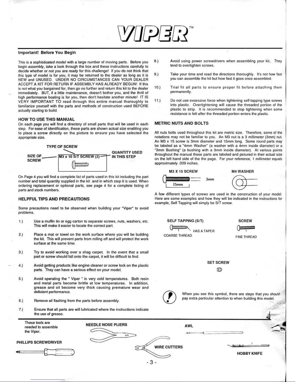
An M3 x 15 screw is 3mm diameter and 15mm long. Some round parts
may
be labeled as a "4mm Washer"
(a
washer with a 4mm inside diameter) 'or a
"3mm Bushing"
(a
bushing with a 3mm inside diameter) . At various points
throughout the manual these parts are labeled and pictured in their actual
size
on
the left hand side of the the page. For your reference. 1 millimeter equals
approximately
.039 inches.
M3X
15SCREW
M4 WASHER
3mm
A few dilferent types
of
screws
are
used in
the
construction
of
your model.
He
re are some examples
and
how they will be indicated
in
the instructions
for
exampl
e.
Sell Tapping will simply be SIT screw.
SELF TAPPING (SfT)
Qiiiiii!IIBP
I " HAS A
TAPER
COARSE THREAD
SETSCREW
@))
SCREW
FINE
THREAD
When you see this symbol, there are steps that you
should
pay extra particul
ar
attention
to
when building this model.
-
~
.....
....
.....
-
-
Ensure that all parts are will lubricated where the instructions indicate
--~~~
th
~e~
us
_e_o_f_g_
re
_a_s_e_·--------------------------------------------------------------------------------
~~~
-
:-
These tools are
6.)
7.)
needed to assemble NEEDLE
NOSE PUERS
AWL
~
.,.
lheViper.
~
PHILUPS SCREWDRIVER
[
HOBBY
KNIFE
. 3 -
Page 4
'
,
b.
.
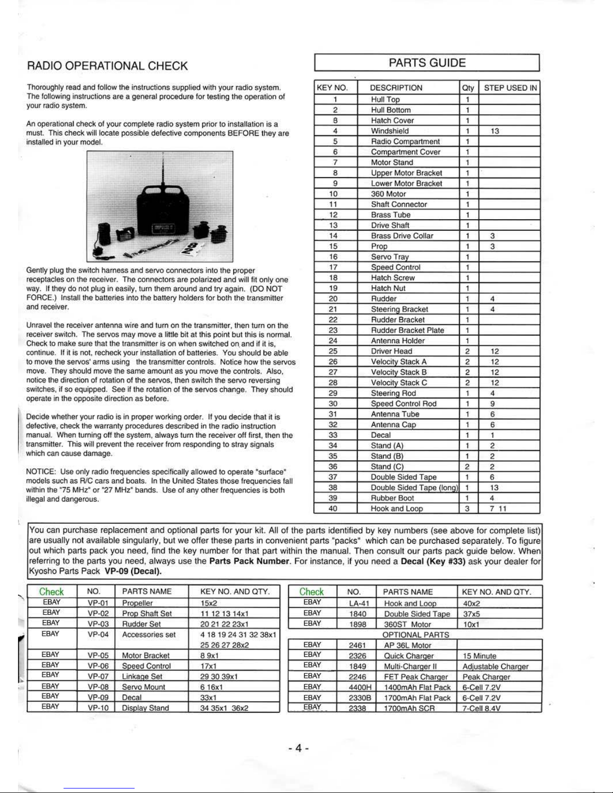
RADIO OPERATIONAL CHECK
Thoroughly read and follow the instructions supplied wilh your radio system.
The
following instructions are a general procedure for testing the oper
ation
of
your radio system.
An operational check of your complete radio system prior to installation is a
must. This check
will locate possible defective components BEFORE t
hey
are
installed in your model.
•
Gently plug the switch harness and servo connectors into the proper
receptacles
on
the
receiver. The connectors
are
polarized and will fit only one
way.
If they
do
not plug in easily, turn them around and try agai
n.
(DO NOT
FORCE
.)
Install the batteries I
nto
the battery holders f
or both
the transmitter
and receiver.
Unravel the receiver antenna wire and
tum
on
the transmitter, then tum
on
the
receiver switch. The servos may move a
little bit at this poi
nt
but this
is
normal.
Check to make
su
re that the transmitter is
on
when switched on. and if
it
is,
continue.
If it is
not
, recheck your installation
of
batteries. You should be able
to move the servos' a
rm
s using t
he
transmitter controls. Notice how the servos
move. They should move the same amount as you move t
he
controls. Also,
no
tice the direction of rotation of t
he
servos, then switch the servo reversing
switch
es,
if so equipped. See if the rotation
of
the servos change. They should
operate in the opposite direction
as
before.
Decide whether your radio is in prop
er
working order. If you decide that it is
defective, check the warranty procedures described in the r
ad
io instruction
manual. When turning off the system, always turn the receiver
off
first, then t
he
transmitter. This will prevent the receiver from responding to stray signals
which can cause damage.
NOTICE: Use only radio frequencies specifically allowed to operate "surface•
models such as RIC cars and boats. In the United States those frequencies fall
within the '75 MHz' or '
27 MHz' bands. Use of any other frequencies is both
ill
ega
l and dangerous.
KEY NO.
1
2
s
4
5
6
7
8
9
10
11
12
13
14
15
16
17
18
19
20
21
22
23
24
25
26
27
28
29
30
31
32
33
34
35
36
37
38
39
40
PARTS
GUIDE
DESCRIPTION
Oty STEP USED IN
Hull
TOfl_
1
Hull Bottom 1
Hatch
Cover 1
Windshield 1 13
Radio
Co
mpartment
1
Compartment Cover
1
Mot
or
Stand 1
l!E2_er
Motor Bracket 1
Lower Motor Bracket 1
360 Motor 1
Shaft Connector 1
Brass Tube 1
Drive
Shaft 1
Brass Drive
Collar
1
3
Prop 1
3
Servo Tray 1
Speed Control
1
Hatch
Screw 1
Hatch
Nut 1
Rudder 1 4
Steerirlg_ Bracket 1
4
Rud der Bracket 1
Rud der Bracket Plate 1
Antenna Holder 1
Dri
ver
Head
2
12
Velocity
Stack A
2
12
Veloci
ty
Stack B
2 12
Veloci
ty
Stack C
2 12
St
eerirlg_
Rod 1 4
Speed Control Rod 1
9
Antenna Tube 1
6
Antennae~
1
6
Decal 1 1
Standj~
1 2
Stand (B) 1
2
Stand (C)
2 2
Double
Sided Tape 1
6
Double
Sided Tape (long
1 13
Rubber Boot 1 4
Ho
ok
and Loop 3 7 11
You
can purchase replaceme
nt
and
optiona
l parts for
you
r ki
t.
All
of the
parts ide
ntifi
ed
by
key numbers (s
ee
above
for
complete list)
are
usua
lly not
available
sing
ularly, but
we
offer these
parts
in convenient parts
"packs" which
can
be pur
chased
separately.
To figu
re
out which parts pack you
need,
find the
key number
for
that
part with
in
the manual. Th
en consu
lt
our
parts
pack gui
de below. When
referring to
the parts you
need, always
use
the
Parts
Pack
Numbe
r.
For
ins
tance, If
you
need a Decal
(Key
#33)
ask
your
dealer for
Kyosho
Parts
Pack VP-09
(Deca
l).
Check
NO. PARTS NAME
KEY
NO. AND OTY.
Check
NO. PARTS NAME KEY NO. AND OTY.
EBA
Y
VP-
01
Propeller
1
5x2
EB
AY
LA-41 Hook
and
Loop 40
x2
EBA
Y
VP-
02
Prop Shaft Set 1
1121314x1
EBAY
1840
Double Sided Tape
37x5
EBA
Y
VP-03
Rudder Set
20
21
22 23x1
EB
AY
1898 360ST Motor 10x1
EBAY
VP-04 Accessories set
4 18 19
24
31
32
38x1 OPTIONAL PARTS
25 26
27 28x2
EBAY
2461 AP 36L Motor
EBAY
VP-
05
Motor Bracket 8
9x1
EBAY
2326
Qu
ick
Charg_er
15 Minute
EBAY
VP-
06
Saeed Control 17x1
EB
AY
1849
Mu
lti-Charger If
Ac:lj_ustable
Charger
EBAY
VP-07 UnkaQe Set
29
30
39x1
EBAY
2246 FET Peak Charger P
eak
Cha!Q!lr
EB
AY
VP-08 Servo
Mount 6 16x1
.EBAY
. 4400H 1400mAh Flal Pack
6-Ceii7
.2V
EBAY
VP-
09
Decal
33x1
EBAY
2330B 1700mAh Fl
at
Pack 6·Ceii7.2V
EBAY
VP-10 Display Stand
34 35x1 36x2
EBAY
1700mAh SCR
7-Ceii8
.4V
. 4 .
Page 5

[I)
APPLYING THE DECALS
Cut-out the decals as close to
the Lines
as
possible. Tho
box
lid
and
photo below can
be
used for
Lhe
placement
of
the decals on the
Viper.
[Ij
ASSEMBLY OF BOAT STAND
Assemble
the
boat
stand
by sliding
the
slots in (
36
)
Stand C into
the
slots
in
(34)
Stan
d A
and
(35)
St
ond
B. Secw·e
A,
Band
C by placing a
few
drops of
cyanoacrylate g
lue on
the slots
.
[Ij
PROP INSTALLATION
MJ
Z"oPLASTIC NUT
©
(1)
SH
AKE PROOF
~
WASHER
'V
(1)
Check
that
the
bra
ss
tube
is
glued
in
.
lf
not, use o
water
proof glue
to
hold the
tube
.
Screw the
(14) Bn!SS Drive
Collar
onto
the
drive
s
han.
Slide
the
(
15)
Po·
op onto the
(
14)
Br
ass
Dri
ve
Collar
so
that
the slot in
the
Prop fi ts over the
Drive
Co
llar
.
'
Lnstall
the
Shake
Proof Washer
and
the
M3.5 plastic
Nut
Tighten
the M3.5 plasti c
Nut
secure!)'·
- 5 -
NOTE
: If
the
Viper will
be
painted
sec
pag
e
11
on
painting
before
appling
the
decals.
In
a pan
of warm
water
place a few drops
of
dish
soap.
Peel
th
e backing o
fT
of the
dccal
and
dip
it
in the water.
Place
the decal on
the
Viper.
The soap
and
wnter
will
allow
the
decal to
be
positioned. Remove
Lhc
excess
water
from
the
decal
(
dab
do
not rub )
and
allow
to
dry.
[H]
I
-
Page 6

•
I
(1]
RUDDER INSTALLATION
M2.6 x 10 SIT SCREW
~
(1)
1 I"' In
stall
the
{39)
Rubber
Boot
in
the
back
of
the
Hull . The Boot goes
to
the insi
de of
the
Hull
.
Cut
ond
remove I mm
(
1116
")
rrom
the
end
or
the
Boot.
lmm
lnstllllthc
(29)
Steering
Rod
so
that
the
large bend
is
outside
the
Hull.
[Ij RADIO INSTALLATION
•
a!'f'
~
.
Remove
the
8 screws
that
hold
the
radio
trny
cover and remove the cover.
lnstnllthe
two servos
as
shown
at
the
right. The
sides
of
the
holes in
the
se.r"o
tray
may
be
trimmed for
larger
servos.
Secure
the
sei"'OS
with
the
serews provided with
the
radio system.
Screw from
radio
system
.
I
nstall
the
{
21)
Steeri
ng
Bracket
on
the
(29)
Steering
RQd. Bend
lhe
end of
the rod 90 deg1·ees down.
The
Stee•·ing Rod
sho
uld
be
installed in
the
outside hole. Slide
the (20) Rudd
er
into
the
(22)
Rudder
Bracket
. Install
the
(2
1)
Steeri
ng
Brack
et
on
the (20) Rudder
.
Secure
the
Steering
Brockel wilh II
M2.6 X 10
srr Screw.
0
~
The
striped
area
~
may
be
trimmed
to
0
fit a
larger
servo.
0
1
•
0
(0
- 6 -
Page 7

L
[I) RECEIVER INSTALLATION
Cl
ean
the bottom
of
the receiver and the back
of
the
raruo
compartme
nt
with alcoho
l.
Place a piece
of
(37)
Double Sided
Tap
e on the bottom of the receiver
and
attach
it
to
the
back
of
the radio compartment.
/
Re~iv(
Louble
Sided Tape
o-
32 Antenna Cap
1----31
Antenna Tube
(f)
Wrap the
re~iver
in a plastic bag to
prevent moisture
from
damaging it.
Route the receiver
antenna
through the (24)
Antenna Hold
er
and
the
(3
1)
Antenna
Tube
. Place the
(3
2)
Antenna Cap over
the
(3
1)
Antenna
Tub
e.
DO
NOT
cut
the excess receiver antenna.
[I]
RECEIVER BATTERY INSTALLATION
Cl
ean
the side
of
the Receiver
Batte1-y
and
the
bottom right side
oflhe
hull beside
the
radio compartment with alcohol. Place a
piece
of
(40)
Hook
and
Loop material on
the Receiver
Battc•-y .
Remove
the paper backing from the oth
er
side
of
the Hook
and
Loop and
install
the
Receiver Battery and Hook and
Loop
to
the
bottom
rigbt
side
of
the
hull next
to
the
raruo
eompm·tment. This
will allow the Receiver
Battery to
be
removed when needed.
-7-
/
-
Page 8

[I) RUDDER CONTROL
Plug the Receiver Battery
and Servos
iniAl
the Receiver.
Turn
the
radio on and
set
the
servo trim levers
to neutral.
0
0
0
0
Trim
lhe
servo
arm
IAl
the shape
and
size shown.
In
sta
ll
the servo
arm
90 degrees
IAl
the
center
line
of
the servo.
The
(29) S
teering
Rod
should be
instal
led in
the
center
hole
NOTE: If more steering is needed
move the
(29)
steering
Rod
to
the outside hole on
the
servo arm.
By
extending
or
contracting
the
bend in the
(29)S
tee
ring Rod
adjust
the
length so
that
lhe
servo
arm
and
steering
bracket
are
parallel.
Install
th
e (30) Speed
Control Ro
d in
the hole 9/16
'"
from
the
center
of
the
servo arm, with the servo arm
in
lhe
neutral position
as
shown
at
the right.
0
By
moving
the
(3
0)
Spe
ed
Control
Rod out
one hole
on
the servo
arm,
\ m
o•·e
speed cont•·ol
~,
, mov7ment can
be
obtained.
'
'
,
'
---------------
~
, ' RIGHT TURN
•,
LE
FT
TURN
'
'
'
· - - -
---
-
r·
.~,
•
SPEED CONTROL MOVEMENT COMPARED TO STI
CK
MOVEMENT
...,
-
'
r
l
HIGH SPEED LOW SPEED NEUTRAL
REVERSE LOW SPEED REVERSE HIGH SPEED
- 8 -
Page 9

j1 ol RECEIVER SWITCH INSTA.LLATION
ST[
Install the receiver switch in
lhe
(6)
Compartm
ent
Cove~
us
ing
the
screws
provided with
the
receiver
switch.
STE 2. Route
the
receiver
antenna
and the receiver battery wire
through
lhe
indentat
ion
in
the radio compartment. rein
staU the
compartment
cover using the 8 screws.
·
ITIJ
BATTERY INSTALLATION
N
OTE: The
battery
will plug in only one
way.
DO
NOT
forc
e it.
S .
Put a strip
of
(40) Hook
and
Loop
ST
al
each end
of
the battery.
.. Remove the paper backing
from
the
(40)
Hook
and
Loop an
d in
sta
ll
the
battery
at
the left.
side of the radio
compartment on the bull bottom.
In
stall the
battery
toward the
front
of
the radjo compartment.
thjs will help balance
the
boat
in
the center.
lftlll£DCH
4iii'Pj(jjf
-
9-
Page 10

1
12
1 DRIVER AND STACK INSTALLATION
M3xa SIT SCREW
•
~
(2)
M3x6SCREW
o-
(6)
M3NUT
@ (6)
NOTE:
The
D1iver
Heads and the
Ve
locity
Stacks may
be
painted
with
a b
ru
sh-on
ena
mel
such
as
Kyosho"s Polyca
Paint.
'""C
. Install the two (
25)
Driv
er
Heads
with two
M3x8 S/1' Screws.
STE-
2. Install the
sLx
(26, 27, 28) Velocity
Stacks.
The
(28
)Velocity
Stack
B
(long) goes to
Lhc
rear.
Then
(27)
Velocity
Stack
A and (26)Veloci
ty
Stack
C (
short
) to
the
front. Use the
six M3x6
Screws
and
M3
Nuts.
1
13
1 WINDSHIELD INSTALLATION
\
•
STE" •. Remove
the
clear
protective covering
from
the
(4)
Windshield.
Sn':P
"'·
Install the long
stlip
of
(38) D
ouble
Sided
T
ape
along the
indentation in front of
the
dri
vcrs.
S,
~?
3. Attach the windshield
to
the
(3)
Hat
ch
Cover.
U is very important to
put
some
styrofoam
in
the hull a.nd the
under side
of
the hatch cover.
This
will all
ow
the
boat to float
should
an
accident occur.
~~~===~
~
-
10-
Page 11

l
Most types
of
paint
such as lacquer
or
epoxy can be
used. The
following is
an
example using lacquer.
SPRAY LACQUER SPRAY LACQUER
PRIMER COLOR
PLASTIC BODY
PUTTY
MASKI
NG
TAPE
THROTTLE
CJ
.
.
SA
ND
PAPEA(120. 240
AND 400 GAIT)
STEERING
FARTHEST
~HOLE
TIGHT
TURN
BATTERY TOO
FAR BACK
N
OSEHIG~
·
s:;:
'-
PAINTING THE VIPER
1.
Fill
any
dents
with
putty
and
sand
smooth.
4.
Spray
several light coats
of
paint
lo
prevent
the
paint
from running.
PUTTY
2.
Sand
using 120
grit
then
240 grit.
vo
·ver to avoid ovcr.spray.
5.Cover
the
area
not
lobe
painted with masking
tope.
Wet
the
surface while lightly
sanding
.
3. Priming
NEWSPAPER
6. Pin
striping
and decals can easily be applied
after
the
paint
has
dried.
<:z
--
··~
Cover
lo
avoid
.,.,.~·
~~
· ·
-#
over sprny.
Spray
with two coats
of
primer
and
allow
lo
dry. Wet
sand
with
400
grit
sand
paper
then
wash
and
dry.
ADJUSTMENTS
FAST FORWA
RD
SLOW FORWARD
NEUTRAL
NEUTRAL
REVERSE
RIGHT
TURN
STEERING TRIM
MIDDLE
HOLE
AVERAGE
TURN
BATTERY IN
MIDDLE
•
WIDE
TURN
BATTERY
TOO FAR
N
OSELEV
EL
~
s:;;;; ·-
N
~
AA
D
For
best
handling
the
boat
should
sit
level in
the
water.
If
the
battery is
too
far
forward ,
the
boat
will
not
get
up
on
plane
and
will be slow.
If
the
battery
is
too
far
back
the
front will bounce up and down, called porpoising.
If
the
boat
turns
too
sharp
it
may
spin
out,
and
the
back
of
the
boat
will flip
around.
- 11 -
-
'
...,.
Page 12

 Loading...