

Kyoritsu Electrical Instruments Works, Ltd. KEW 5410 Instruction Manual
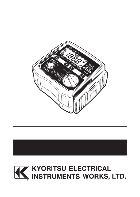
DIGITAL RCD(ELCB) TESTER
KEW 5410
INSTRUCTION MANUAL

Contents
1. Safety Warnings ………………………………………………….………….. 1
2. Procedure of removing Cover …………………………………………….… 3
2-1 Method of removing the Cover ………………………………………… 3
2-2 Method of storing the Cover ……………………………………….…. 3
3. Feature …………….…………………………………..…………………….…. 4
4. Specification ……………………………………………..…..…………….…. 5
5. Instrument Layout …………………………………………………………… 8
6. Measurement principle ……………………………………………………
.... 10
7. Preparation …………………………………………………………………... 11
7-1 Connection of Test Leads ………………………………………….… 11
7-2 Setting of Measurement Range …………………………………….... 11
7-3 Setting of IΔn ……………………………………………………….….. 12
7-4 Setting of Test Polarity …………………………………………….…. 12
7-5 Backlight ………………………………………………………………... 12
8. Measurements ……………………………………………………………... 13
8-1 Connection ………………………………………………………….…. 13
8-2 Voltage Measurement ……………………………………………….... 13
8-3 RCD Test ………………………………………………………..……... 14
8-4 Remote Test ……………………………………………………...….…. 14
8-5 Operating time ………………………………………………..……..…. 18
9. Battery Replacement …………………………………………………….... 19
10. Strap Belt Assembly ……………………………………………………..… 20
Symbols used on the instrument
CAT.II
Pri mar y ele ctrical circuit s of equip men t connected to an AC
electrical outlet by a power cord.
CAT.III
Primary electrical circuits of the equipment connected directly to the
distribution panel, and feeders from the distribution panel to outlets.
Protected throughout by DOUBLE INSULATION or REINFORCED
INSULATION
User must refer to the explanations in the instruction manual.
Earth Ground

1
1. Safety Warnings
This instrument has been designed, manufactured and tested according to
following standards, and delivered in the best condition after passing quality
control tests.
● IEC61010-1 Measurement Category CAT.III 300V / CAT.ll 400V
Pollution degree 2
● IEC61010-031
● IEC61557-1, 6
● IEC60529 IP54
This instruction manual contains warnings and safety rules which have
to be observed by
the user to ensure safe operation of the instrument
and to main tain it in safe condition. Therefore, read throu gh the se
operating instructions before using the instrument.
DANGER
● Read through and understand the instructions contained in this manual
before using the instrument.
●
Keep the manual at hand to enable quick reference whenever necessary.
● The instrument is to be used only in its intended applications.
●
Understand and follow all the safety instructions contained in the manual.
It is essential that the above instructions are adhered to. Failure to follow
the above inst ruc tions may cause inju ry, ins trument dama ge and/or
damage to equipment under test.
●
The symbol indicated on the instrument means that the user must refer to the
related parts in the manual for safe operation of
the instrument. It is essential to
read the instructions wherever the
symbol appears in the manual.
DANGER is reserved for conditions and action s that are likely to
cause serious or fatal injury.
WARNING is res erv ed fo r con dit ions and acti ons that can cause
serious or fatal injury.
CAUTION is reserved for conditions and actions that can cause injury
or instrument damage.
2
DANGER
● This instrument is designed to measure the earth-to-line voltage 90 ~
264V and the line-to-line voltage up to 440V (50/60Hz). Do not exceed
the maximum allowable input of any measuring range.
● Do not attempt to make measurement in the presence of flammable
gasses. Otherwise, the use of the instrument may cause sparking,
which can lead to an explosion.
● Keep your fingers behind the safe
ty barrier on the test leads.
● Set the Fun ction Swi tch to a ny desira ble Range before making a
measurement. Do not power on the instrument with it being connected
to the live circuit.
● Never attempt to use the instrument if its surface or your hand are wet.
● Never open the Battery Cover during a measurement.
● Verify proper operation on a known source before use or taking action
as a result of the
indication.
WARNING
● Never attempt to make any measurement if any abnormal conditions,
such as a broken cover or exposed metal parts are present on the
Instrument and test leads.
● Do not in stall substit ut e part s or ma ke any mo dific at io n to the
instrument. Return the instrument to your local KYORITSU distributor
for repair or re-calibration in case of suspected faulty operation.
● Set the Funct
ion Switch to the OFF position when removing the Battery
Cover for battery replacement.
● If the overheat symbol “
” appears on the display, disconnect the
instrument from the measuring point and allow to cool down.
CAUTION
● Firmly insert the plugs of test leads to the appropriate terminals.
● Set the Function switch to the OFF position after use, and remove the
batteries if the instrument is to be stored and will not be in use for a
long period.
● Use a damp cloth with neutral detergent for cleaning the inst
rument.
Do not use abrasives or solvents.
● Do not store the instrument if it is wet.
3
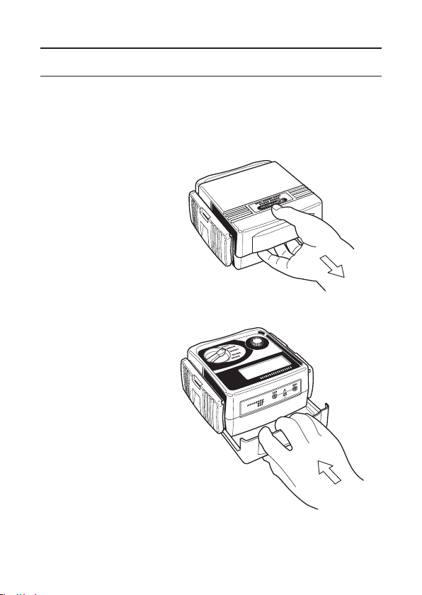
2. Procedure of removing Cover
KEW5410 has a dedicated Cover to protect against impacts from the outside
and preve nt the operatio n part, the LCD and the Con nector Block from
becoming dirty. The Cover can be detached and put on the backside of the
main body during measurement.
2-1 Method of removing the Cover
Slide and pull the Cover
in the direction of an arrow.
2-2 Method of storing the Cover
Turn the
Cover, slide and
push it in the direction of
arrow.
Fig. 1
Fig. 2

4
3. Feature
This instrument is a digital RCD Tester to measure the trip time and trip out
current of RCDs. It also equips the function to measure the voltage.
● Measurement of RCD trip time
Conducting testing of rated residual non-operating currents at x 1/2 Range,
measuring RCD trip time at x1 and x5 Ranges.
● Measurement of trip out current
Measuring trip out current by varying current automati
cally.
● Remote Test
Enabling a user to hold the Test Leads with his both hands by locking the
Test Button.
● Voltage Measurement
Carrying out a constant measurement of voltage in the stand-by mode at
each Range.
● Auto-detection of Contact voltage
Detecting the voltage to earth of Earth electrodes or Protective conductors
during RCD test
-
when applying test currents - at measurement using
EAR
TH in order to prevent electrical shocks caus ed by the damaged
earth.
Measurement will be ceased at AC50V (AC100V “x5 range” only) or more.
● Dust- and Water-proof
Dust- and Water-proof construction (designed to IEC60529 IP54)
● Backlight
Facilitating working at dimly illuminated locations.
5
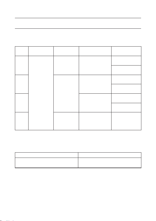
4. Specification
● Measuring range and accuracy
(23℃±5℃ , relative humidity 75% or less)
Range Rated Voltage
Test current
IΔn
Measuring
range
Accuracy
x 5
100V±10%
200V+32%
/-10%
400V±10%
50 / 60Hz
15 / 30 / 50
/ 100mA
Testing time
0ms ~ 200ms
Trip Time
±(1%rdg+3dgt)
Test Current
+2% ~ +8%
x 1
15 / 30 / 50
/ 100 / 200
/ 500mA
Testing time
0ms ~ 2000ms
Trip Time
±(1%rdg+3dgt)
Test Current
+2% ~ +8%
x 1 / 2
Testing time
0ms ~ 2000ms
Trip Time
±(1%rdg+3dgt)
Test Current
-8% ~ -2%
AUTO
RAMP
(mA)
15 / 30 / 50
/ 100 / 200
/ 500mA
40%
~110% of IΔn
(goes up by 5%)
Testing time
300ms x 15steps
Test Current
at each step
-4% ~ +4%
* Only the RCD type G (without trip out time-delay) can be tested at Auto
Ramp Test; type S (time-delay) cannot be tested.
Voltage Measurement
Measuring range Accuracy
80V ~ 450V
50 / 60Hz
±(2%rdg+4dgt)
● Applied standards : IE C61010-1 Measurement Category CAT. II I
300V / CAT.II 400V, Pollution degree 2
IEC61010-031
IEC61557-1, 6
IEC60529 IP54
● Display : 1999counts (3 1/2digits), Large LCD

6
● Used location : Altitude up to 2000m, indoor use
● Operating temperature :
& humidity
0℃ ~ 40℃ , relative humidity 85%
(no condensation)
● Storage temperature :
& humidity
-20℃ ~ 60℃ , relative humidity 85%
(no condensation)
● Withstand Voltage : AC3700V / 1 min
(between electrical circuit and enclosure)
● Insulation resistance : 50MΩ or more / 1000V
(between electrical circuit and enclosure)
● Sleep Functi
on : 1. Automatically enters Sleep mode in 3 min after
the last switch operation (current consumption
75uA). This function doesn't work at voltage
measurements. To exit from the Sleep mode,
se t th e Func ti on s wi tc h to OF F po si tio n
once, and re-set it to the Range at which a
measurement to be conducted.
2. Backlight turns off in 1 min after it lights up.
● Dimension : 186mm x 167mm x 89mm
● Weight : 965
g
● Power Source : DC12V / Size AA battery R6P (SUM-3) x 8pcs
● Possible number of : 1200 times or more
Measurements (measure every 30sec at x1/2 Range,
IΔn =100mA)
● Accessories : Instruction manual x 1pce
Strap belt x 1pce
Test lead M7128 x 1set (red & black cords)
Test lead with alligator clip M7129 x 1 set
Cord case x 1pce
Long pin M8017 x 2pcs
Size AA battery R6P(SUM-3) x 8pcs
 Loading...