

Page 1
INSTRUCTION MANUAL
VOLTAGE SENSOR
VOLTAGE SENSOR Series
KEW 8309
1. SAFETY WARNINGS
This instrument has been designed and tested according to IEC 61010:
Safety Requirements for Electronic Measuring Apparatus, and
delivered in the best condition after passing quality control tests.
This instruction manual contains warnings and safety rules which
have to be observed by the user to ensure safe operation of the
instrument and to maintain it in safe condition.
Therefore, read through these operating instructions before using
the instrument.
# WARNING
● Read through and understand instructions contained in this
manual before using the instrument.
● Keep the manual at hand to enable quick reference
whenever necessary.
● The instrument is to be used only in its intended applications.
● Understand and follow all the safety instructions contained in
the manual.
It is essential that the above instructions are adhered to. Failure
to follow the above instructions may cause injury, instrument
damage and/or damage to equipment under test.
Kyoritsu is by no means liable for any damage resulting from
the instrument in contradiction to this cautionary note.
The symbol # indicated on the instrument, means that the user
must refer to the related parts in the manual for safe operation of
the instrument.
It is essential to read the instructions wherever the # symbol
appears in the manual.
# DANGER is reserved for conditions and actions that are
likely to cause serious or fatal injury.
# WARNING is reserved for conditions and actions that can
cause serious or fatal injury.
# CAUTION is reserved for conditions and actions that can
cause injury or instrument damage.
● Never make measurement on a circuit in which the electrical
potential exceeds AC600V.
● Do not make measurement when thunder rumbling. If the
instrument is in use, stop the measurement immediately and
remove the instrument from the equipment under test.
● Do not attempt to make measurement in the presence of
flammable gasses. Otherwise, the use of the instrument may
cause sparking, which can lead to an explosion.
●
The Measuring Terminals are made of metal and they are not
completely insulated. Be especially careful about the possible
shorting where the measured conductor is not insulated.
●
Never use these sensors when their surface or your hand is wet.
Do not wet the output connector of KEW 8309WP because it
isn't dust/ water-proof.
● Remove the Measuring terminals from the circuit under test
before connecting/inserting the Output connector.
● Do not exceed the maximum allowable input of any
measuring range.
● Never open the Bottom Case of the instrument during
measurement.
● Never attempt to make any measurement if any abnormal
conditions, such as a broken cover or exposed metal parts
are present on the instrument.
● Do not install substitute parts or make any modification to the
instrument.
Return the instrument to your local KYORITSU distributor for
repair or re-calibration in case of suspected faulty operation.
● Stop using the test lead if the outer jacket is damaged and
the inner metal or color jacket is exposed.
● Do not step on or pinch the cord, or it may damage the
jacket of cord.
● Hold the inserting part (except for the cable) and disconnect
the Output connector from a measuring instrument so as not
to cause a break in the cord.
● Put the instrument on a stable place where is free from
vibrations or shocks.
● Firmly fix the Sensor unit and Measuring terminal so that
they don't fall off due to the weight of test leads.
●
Keep away Floppy Disks, Mag Cards, PCs and Displays from
the magnet, which is attached to the backside of the instrument.
● Do not expose the instrument to direct sunlight, high
temperatures, humidity or dew.
● Not to give shocks, such as vibration or drop, which may
damage the instrument.
● Use a damp cloth with neutral detergent for cleaning the
instrument. Do not use abrasives or solvents.
● Keep your fingers and hands behind the protective
fingerguard during measurement.
# DANGER
# WARNING
# CAUTION
Safety symbols
Refer to the instructions in the manual.
#
Indicates instruments with double or reinforced
insulation
Indicates that this instrument can clamp on live bare
conductors when the voltage to be tested is below
Circuit - Ground-to-Earth voltage against the indicated
Measurement Category.
Indicates AC
○ Measurement Category
To ensure safe operation of measuring instruments, IEC 61010
establishes safety standards for various electrical environ-ments,
categorized as O to CAT IV, and called measurement categories.
Higher-numbered categories correspond to electrical environments
with greater momentary energy, so a measuring instrument
designed for CAT III environments can endure greater momentary
energy than one designed for CAT II.
O : Circuits which are not directly connected to the mains
power supply.
CAT II : Electrical circuits of equipment connected to an AC
electrical outlet by a power cord.
CAT III : Primary electrical circuits of the equipment connected
directly to the distribution panel, and feeders from the
distribution panel to outlets.
CAT IV : The circuit from the service drop to the service
entrance, and to the power meter and primary
overcurrent protection device (distribution panel).
Incoming wire
Socket
Interior wiring
Device which is
O:
not directly
connected to the
mains power supply
2. FEATURES
• This is a Sensor to measure AC voltage up to 600V.
• Designed to following international safety standards:
IEC 61010-1 Measurement Category (CAT.) III 600V
IEC 61010-031 Requirements for hand-held probes
• Installed differential amplifier enables measurement of floating
voltage.
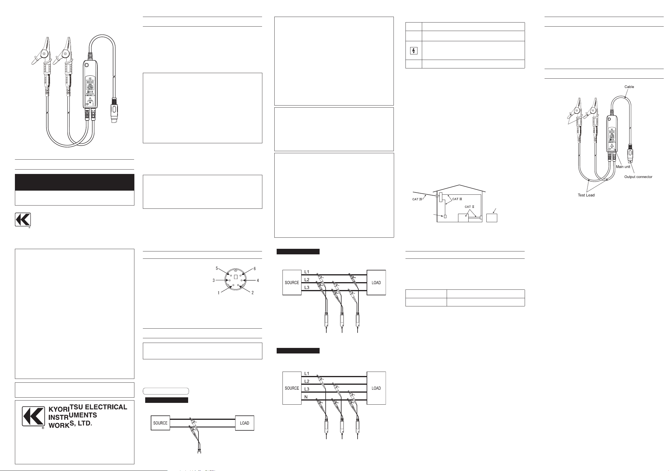
3. INSTRUMENT LAYOUT
Protective
fingerguard
Protective fingerguard :
It is a part providing protection against electrical shock and
ensuring the minimum required air and creepage distances.
DISTRIBUTOR
Kyoritsu reserves the rights
described in this manual without notice and without obligations.
to change specifications or designs
● Three-phase 3-wire
4. DIN PLUG PIN ASSIGNMENT
1 : DC Power Pin / Positive
( +3~+5V)
2 : DC Power Pin / Negative
( -3~-5V)
3 : GND pin
5 : Output signal pin
6 : Sensor recognition pin
(Resistance between Pin 3 and Pin 6: 3.3kΩ
4 : No use
* Above figure shows the pin assignment seeing the Clamp sensor from
output connector part. The figure of the pin assignment of connection
terminal is symmetrical to above figure.
5. OPERATING INSTRUCTIONS
This sensor operates on a power provided via Output
Connector. Rated voltage should be applied to the positive/
negative DC Power Pins to get correct indication.
(1) Connect the Output Connector of the Sensor to the input
terminal of the measuring instrument.
(2) Connect the V and COM Measuring terminals to the
conductors under test.
(3) Take the readings on the measuring instrument.
Example of connection
● Single-phase 2-wire
Find Quality Products Online at: sales@GlobalTestSupply.com
Example of Floating Voltage measurement with Three KEW 8309
● Three-phase 4-wire
Measurement example with Three KEW 8309
www.GlobalTestSupply.com
6. SPECIFICATIONS
• Max. input voltage
AC600Vrms(sin), 848.4V Peak
• Output voltage
AC0 ~ 60mV (Output/Input: 0.1mV/V)
• Measuring ranges and accuracy
Measuring Range Accuracy (Frequency range)
6 ~ 600V ±1.0%rdg±0.1mV(50/60Hz)
• Temperature and Humidity Ranges (guaranteed accuracy):
23ºC±5ºC,relative humidity 85%or less (without condensation)
• Operating Temperature and Humidity Ranges:
-10-~50ºC,relative humidity 85%or less (without condensation)
• Storage Temperature and Humidity Ranges
-20~60ºC,relative humidity 85%or less (without condensation)
• Supply Voltage ( from Output Connector)
DC±3V~±5V
• Input impedance:
Approx.3.4MΩ
• Output impedance:
Approx.180MΩ
• Location for use:
Altitude up to 2000m, Indoors
• Standards (Safety):
IEC / EN 61010-1: CAT III 600V, pollution degree 2
IEC / EN 61010-031
IEC 61326-1 (EMC)
EN50581(RoHS)
• Withstand Voltage:
5160V (rms 50/60Hz) for 5 sec., between measuring
terminal and enclosure
• Insulation Resistance:
50MΩor greater at 1000V,between measuring terminal and
enclosure
• Dimensions, Weight :
87(L) x 26(W) x 17(D)mm (excluding protrusions)
Approx.135g
• V,COM Cable length:
Approx. 0.9m
• Test Lead Length:
Approx. 1m
• Output Connector:
MINI DIN 6PIN
• Accessories:
Instruction manual
• Option:
7185 (Extension cable)
7197 (small Alligator clip)
 Loading...