

Page 1

INSTRUCTION MANUAL
DIGITAL RCD(ELCB) TESTER
KEW 5410
Find Quality Products Online at: sales@GlobalTestSupply.com
www.GlobalTestSupply.com
Page 2

Contents
1. Safety Warnings ………………………………………………….………….. 1
2. Procedure of removing Cover …………………………………………….… 3
2-1 Method of removing the Cover ………………………………………… 3
2-2 Method of storing the Cover ……………………………………….…. 3
3. Feature …………….…………………………………..…………………….…. 4
4. Specification ……………………………………………..…..…………….…. 5
5. Instrument Layout …………………………………………………………… 8
6. Measurement principle ……………………………………………………
7. Preparation …………………………………………………………………... 11
7-1 Connection of Test Leads ………………………………………….… 11
7-2 Setting of Measurement Range …………………………………….... 11
7-3 Setting of IΔn ……………………………………………………….….. 12
7-4 Setting of Test Polarity …………………………………………….…. 12
7-5 Backlight ………………………………………………………………... 12
8. Measurements ……………………………………………………………... 13
8-1 Connection ………………………………………………………….…. 13
8
-2 Voltage Measurement ……………………………………………….... 13
8-3 RCD Test ………………………………………………………..……... 14
8-4 Remote Test ……………………………………………………...….…. 14
8-5 Operating time ………………………………………………..……..…. 18
9. Battery Replacement …………………………………………………….... 19
10. Strap Belt Assembly ……………………………………………………..… 20
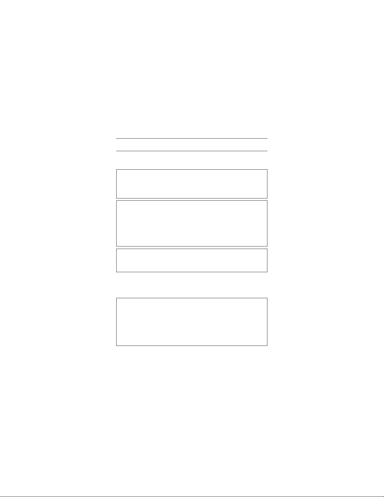
Symbols used on the instrument
Pri mary elec tri cal circuits of equip ment connect ed to an AC
CAT.II
electrical outlet by a power cord.
Primary electrical circuits of the equipment connected directly to the
CAT.III
distribution panel, and feeders from the distribution panel to outlets.
Protected throughout by DOUBLE INSULATION or REINFORCED
INSULATION
User must refer to the explanations in the instruction manual.
.... 10
Earth Ground
Find Quality Products Online at: sales@GlobalTestSupply.com
www.GlobalTestSupply.com
Page 3
1. Safety Warnings
This instrument has been designed, manufactured and tested according to
following standards, and delivered in the best condition after passing quality
control tests.
● IEC61010-1 Measurement Category CAT.III 300V / CAT.ll 400V
Pollution degree 2
● IEC61010-031
● IEC61557-1, 6
● IEC60529 IP54
This instruction manual contains warnings and safety rules which have
to be observed by
and to maintain it in safe con dit ion. The ref ore , read through th ese
operating instructions before using the instrument.
● Read through and understand the instructions contained in this manual
before using the instrument.
●
Keep the manual at hand to enable quick reference whenever necessary.
● The instrument is to be used only in its intended applications.
●
Understand and follow all the safety instructions contained in the manual.
It is essential that the above instructions are adhered to. Failure to follow
the above instruction s may cau se injur y, ins tru men t da mag e and/o r
damage to equipment under test.
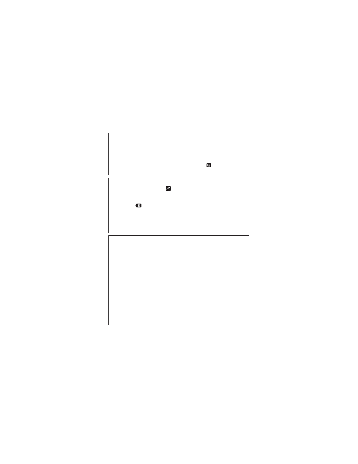
●
The symbol indicated on the instrument means that the user must refer to the
related parts in the manual for safe operation of the i
read the instructions wherever the
DANGER is reserved for conditions and action s that are likely to
WARNING is reser ved for condi tio ns and acti ons tha t ca n ca use
CAUTION is reserved for conditions and actions that can cause injury
t
he user to ensure safe operation of the instrument
DANGER
symbol appears in the manual.
cause serious or fatal injury.
serious or fatal injury.
or instrument damage.
nstrument. It is essential to
1
Find Quality Products Online at: sales@GlobalTestSupply.com
www.GlobalTestSupply.com
Page 4
DANGER
● This instrument is designed to measure the earth-to-line voltage 90 ~
264V and the line-to-line voltage up to 440V (50/60Hz). Do not exceed
the maximum allowable input of any measuring range.
● Do not attempt to make measurement in the presence of flammable
gasses. Otherwise, the use of the instrument may cause sparking,
which can lead to an explosion.
● Keep your fingers behind the safe
● Set the Fu nction Switch to any desirable Ran ge before mak ing a
measurement. Do not power on the instrument with it being connected
to the live circuit.
● Never attempt to use the instrument if its surface or your hand are wet.
● Never open the Battery Cover during a measurement.
● Verify proper operation on a known source before use or taking action
as a result of the
● Never attempt to make any measurement if any abnormal conditions,
such as a broken cover or exposed metal parts are present on the
Instrument and test leads.
● Do not insta ll substi tu te parts o r make any mod if icati on to the
instrument. Return the instrument to your local KYORITSU distributor
for repair or re-calibration in case of suspected faulty operation.
● Set the Funct
Cover for battery replacement.
● If the overheat symbol “
instrument from the measuring point and allow to cool down.
● Firmly insert the plugs of test leads to the appropriate terminals.
● Set the Function switch to the OFF position after use, and remove the
batteries if the instrument is to be stored and will not be in use for a
long period.
● Use a damp cloth with neutral detergent for cleaning the inst
Do not use abrasives or solvents.
● Do not store the instrument if it is wet.
indication.
ion Switch to the OFF position when removing the Battery
ty barrier on the test leads.
WARNING
” appears on the display, disconnect the
CAUTION
rument.
2
Find Quality Products Online at: sales@GlobalTestSupply.com
www.GlobalTestSupply.com
Page 5
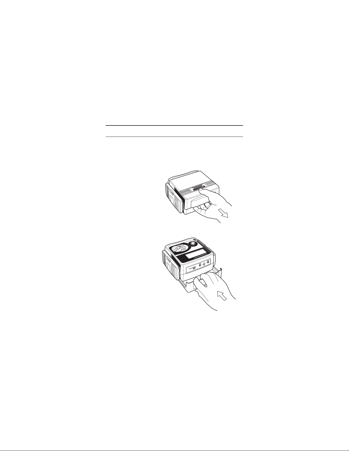
2. Procedure of removing Cover
KEW5410 has a dedicated Cover to protect against impacts from the outside
and preve nt the ope rat ion part, the LCD an d the Connector Block from
becoming dirty. The Cover can be detached and put on the backside of the
main body during measurement.
2-1 Method of removing the Cover
Slide and pull the Cover
in the direction of an arrow.
2-2 Method of storing the Cover
slide and
Cover,
Turn the
push it in the direction of
arrow.
Fig. 1
Fig. 2
3
Find Quality Products Online at: sales@GlobalTestSupply.com
www.GlobalTestSupply.com
Page 6

3. Feature
This instrument is a digital RCD Tester to measure the trip time and trip out
current of RCDs. It also equips the function to measure the voltage.
● Measurement of RCD trip time
Conducting testing of rated residual non-operating currents at x 1/2 Range,
measuring RCD trip time at x1 and x5 Ranges.
● Measurement of trip out current
Measuring trip out current by varying current automati
Remote Test
●
Enabling a user to hold the Test Leads with his both hands by locking the
Test Button.
● Voltage Measurement
Carrying out a constant measurement of voltage in the stand-by mode at
each Range.
● Auto-detection of Contact voltage
Detecting the voltage to earth of Earth electrodes or Protective conductors
during RCD test
in order to prevent electr ical shoc ks ca used by the damaged
EARTH
earth.
Measurement will be ceased at AC50V (AC100V “x5 range” only) or more.
● Dust- and Water-proof
Dust- and Water-proof construction (designed to IEC60529 IP54)
● Backlight
Facilitating working at dimly illuminated locations.
-
when applying test currents - at measurement using
4
cally.
Find Quality Products Online at: sales@GlobalTestSupply.com
www.GlobalTestSupply.com
Page 7
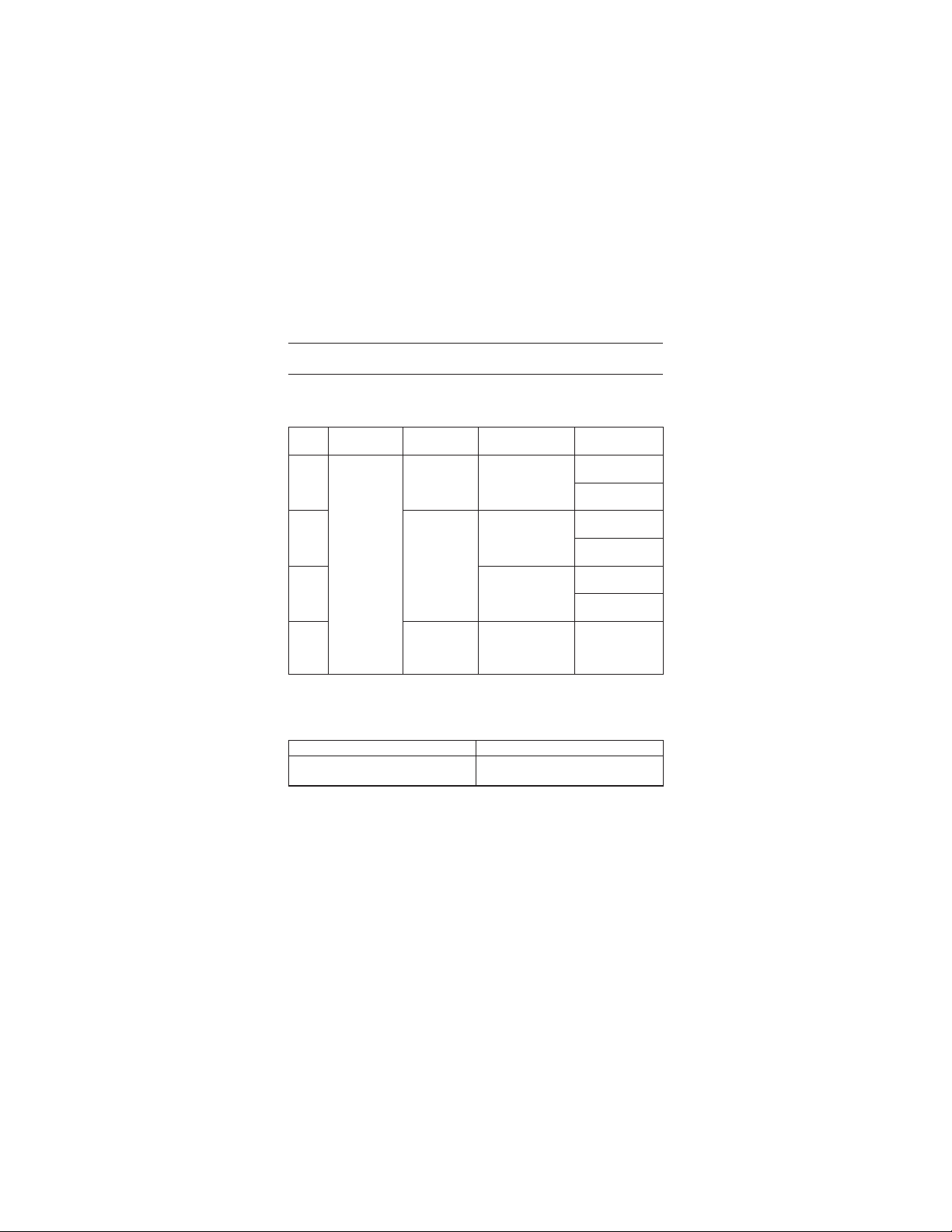
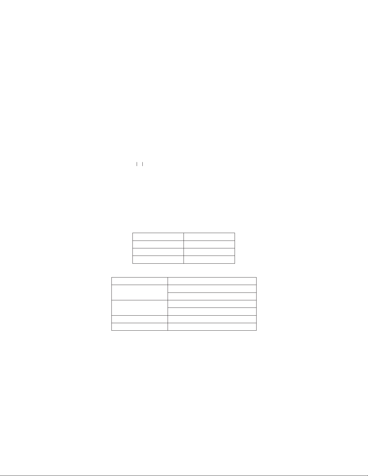
4. Specification
● Measuring range and accuracy
(23℃±5℃ , relative humidity 75% or less)
Range Rated Voltage
x 5
x 1
100V±10%
200V+32%
/-10%
400V±10%
x 1 / 2
AUTO
RAMP
* Only the RCD type G (without trip out time-delay) can be tested at Auto
Voltage Measurement
● Applied standards : IE C610 10-1 M ea sur em ent Ca te gor y CAT.III
● Display : 1999counts (3 1/2digits), Large LCD
50 / 60Hz
(mA)
Ramp Test; type S (time-delay) cannot be tested.
Measuring range Accuracy
80V ~ 450V
50 / 60Hz
Test current
IΔn
15 / 30 / 50
/ 100mA
15 / 30 / 50
/ 100 / 200
/ 500mA
15 / 30 / 50
/ 100 / 200
/ 500mA
300V / CAT.II 400V, Pollution degree 2
IEC61010-031
IEC61557-1, 6
IEC60529 IP54
Measuring
range
Testing time
0ms ~ 200ms
Testing time
0ms ~ 2000ms
Testing time
0ms ~ 2000ms
~11
0% of IΔn
40%
(goes up by 5%)
Testing time
300ms x 15steps
±(2%rdg+4dgt)
Accuracy
Trip Time
±(1%rdg+3dgt)
Test Current
+2% ~ +8%
Trip Time
±(1%rdg+3dgt)
Test Current
+2% ~ +8%
Trip Time
±(1%rdg+3dgt)
Test Current
-8% ~ -2%
Test Current
at each step
-4% ~ +4%
5
Find Quality Products Online at: sales@GlobalTestSupply.com
www.GlobalTestSupply.com
Page 8

● Used location : Altitude up to 2000m, indoor use
● Operating temperature :
& humidity
● Storage temperature :
& humidity
● Withstand Voltage : AC3700V / 1 min
● Insulation resistance : 50MΩ or more / 1000V
● Sleep Functi
● Dimension : 186mm x 167mm x 89mm
● Weight : 9
● Power Source : DC12V / Size AA battery R6P (SUM-3) x 8pcs
● Possible number of : 1200 times or more
Measurements (measure every 30sec at x1/2 Range,
● Accessories : Instruction manual x 1pce
on : 1. Automatically enters Sleep mode in 3 min after
0℃ ~ 40℃ , relative humidity 85%
(no condensation)
-20℃ ~ 60℃ , relative humidity 85%
(no condensation)
(between electrical circuit and enclosure)
(between electrical circuit and enclosure)
the last switch operation (current consumption
75uA). This function doesn't work at voltage
measurements. To exit from the Sleep mode,
se t th e Fu n ct i on swi t ch to OF F po si t ion
once, and re-set it to the Range at which a
measurement to be conducted.
2. Backlight turns off in 1 min after it lights up.
65g
IΔn =100mA)
Strap belt x 1pce
Test lead M7128 x 1set (red & black cords)
Test lead with alligator clip M7129 x 1 set
Cord case x 1pce
Long pin M8017 x 2pcs
Size AA battery R6P(SUM-3) x 8pcs
6
Find Quality Products Online at: sales@GlobalTestSupply.com
www.GlobalTestSupply.com
Page 9
● Operating error
Operating error (B) is an e rro r obtain ed under the nom inal ope rating
conditions, and calculated with the intrinsic error (A), which is an error of
the instrument used, and the error (En) due to variations.
2
2
2
2
B=±(
A +1.15
----------------
E
+E
+E
1
2
√
3
+E
2
+E
5
8
)
A : Intrinsic error
: Variation due to changing the position
E
1
: Variation due to changing the supply voltage
E
2
: Variation due to temperature
E
3
: Variation due to the resistance of Probe *
E
5
: Influence by the variation in System Voltage
E
8
* Probe = auxiliary Earth electrode to be used for the sampling of
electric potentials during measurements
IΔn Probe resistance
15mA Less than 200Ω
30mA Less than 100Ω
50/100/200/500mA Less than 20Ω
KEW5410 Max Operating Error (IEC61557)
Range Max Operating Error
x 5
x 1
test current 0% ~ +10%
time measurement ±10%
test current 0% ~ +10%
time measurement ±10%
x 1/2 test current -10% ~ 0%
AUTO RAMP (mA) ±6%
7
Find Quality Products Online at: sales@GlobalTestSupply.com
www.GlobalTestSupply.com
Page 10

5. Instrument Layout
1
2
3
4
1. LCD
2. 0° / 180° Button (Polarity change)
3. IΔn Button
4. Test Button
5. Backlight Button
6. Function Switch
Connector Block LCD
Fig. 3
8
5
6
Find Quality Products Online at: sales@GlobalTestSupply.com
www.GlobalTestSupply.com
Page 11
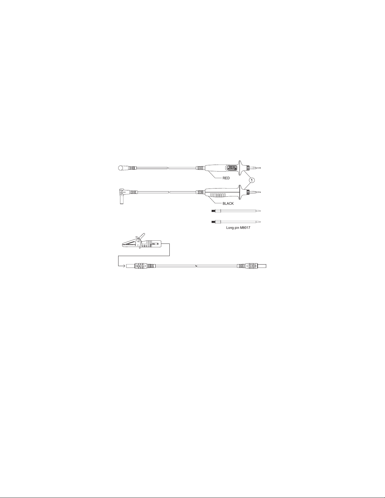
Test Lead
1. Test Lead M7128
2. Test lead with alligator clip M7129
Fig. 4
* Long pin for M7128
The Tip pin of M7128 can be replaced with the Long pin M8017.
(1) Unscrew and remove ① shown in Fig.4 and remove the Tip pin.
(2) Install the Long pin and tighten ①.
9
Find Quality Products Online at: sales@GlobalTestSupply.com
www.GlobalTestSupply.com
Page 12

6. Measurement principle
This instrument has a constant current circuit, and drives leakage currents (I)
between LINE-NEUTRAL as illustrated in Fig.5 to activate RCDs, moreover,
can output and measure leakage currents flowing to the earth as shown in
Fig.6.
● Trip time measurement:
Measure and displ ay the time be tween th e start of d riv ing leaka ge
currents (I) and trip of the RCD.
● Trip out cur
Increase the leakage current gradually from the 40% of IΔn, the current
value when RCD trips is displayed.
Influence of the fluctuations in system voltages is less on this instrument due
to the incorporated constant current circuit.
rent measurement:
Fig. 5 Fig. 6
10
Find Quality Products Online at: sales@GlobalTestSupply.com
www.GlobalTestSupply.com
Page 13

7. Preparation
7-1 Connection of Test Leads
Connect the test lead properly.
● Connect the test lead M7128; red cord to the load of the Connector
block and black cord to the power supply.
● When using the test lead with Alligator clip, connect the test lead M7128
(red) to the load of Connector block and M7129 to the power.
7-2 Setting of Measurement Range
Turn the Fun ction Sw itch and power on the in
appropriate Ranges.
Range construction: There are 4 Ranges on this instrument.
For trip time measurement :
x 5
Apply a current 5 times bigger than IΔn to measure RCD trip
time.
For trip time measurement :
x 1
Apply IΔn to measure RCD trip time.
For the test - rated residual non-operating current :
x 1/2
Apply a half of IΔn to confirm the RCD under test doesn't trip.
AUTO
RAMP
Do not power on the instrument with it being connected to the live circuit.
For trip out current measurement :
Vary a testing current in the range of 40% ~ 110% of IΔn to
measure the trip
out current on the RCD.
WARNING
11
strument, then select any
Find Quality Products Online at: sales@GlobalTestSupply.com
www.GlobalTestSupply.com
Page 14

7-3 Setting of IΔn
Balance the IΔn of the instrument and of the RCD by using the IΔn Button.
● Default value : 30mA
● Selectable values at x 5 Range are 15, 30, 50 and 100mA;
200 and 500mA are not available (Black arrow mark “▼” on the LCD
indicates the selected value). In case that 200 or 500 mA is selected at
any Ranges other than x 5 Range and set the Function Switch to x 5
Range, the value
7-4 Setting of Test Polarity
Press the 0° /180° Button and select the polarity for test.
When the instrument is connected as illustrated in Fig.7, 8; current flows from
the load to power in positive half cycle at 0° and flows from the load to power
in negative half cycle at 180° , and when it is connected as illustrated in Fig.9;
current flows from the load to earth i
the load to earth in negative half cycle at 180° .
● Default polarity : 0°
7-5 Backlight
Press the Backlight Button and turns on the backlight to facilitate working at
dimly illuminated location.
● Backlight turns off automatically in 1 min after it lights up.
Press the button again to turn it on.
automatically restores to 30mA.
positive half cycle at 0° and flows from
n
12
Find Quality Products Online at: sales@GlobalTestSupply.com
www.GlobalTestSupply.com
Page 15
8. Measurements
8-1 Connection
Connect the instrument according to Fig. 7, 8, 9.
DANGER
This instrument is designed to measure the earth-to-line voltage 90 ~
264V and the line-to-line voltage up to 440V (50/60Hz). Do not exceed
the maximum allowable input of any measuring range.
● Power on the instrument before connecting to the measuring point.
Prior to a measurement, confirm that the instrument isn't in the Sleep
●
mode. If it is in the sleep mode, set the Function Switch to OFF position
first and do p reparation for measurement according to “ Chapter 7.
Preparation ”.
Then connect the instrument to the measuring point.
Dis connect the lo ad of the RCD to be teste d be for e co nnecting the
instrument. Otherwise, it may influence on the test results.
8-2 Voltage Measurement
nstrume nt au tomatic ally measure voltages when it detects input of
The i
voltage.
Indication of “Lo V” is displayed on the LCD when the measured voltage
is less than 80V; “H i V” is displayed with audible wa rni ng when the
measured voltage is 450V or higher. Disconnect the instrument from the
measuring point immediately when “Hi V” is displayed on the LCD, and
stop further measurements. The Test But
“Hi V” is displayed on the LCD, and RCD test cannot be performed.
WARNING
CAUTION
DANGER
ton is disabled while “Lo V” or
13
Find Quality Products Online at: sales@GlobalTestSupply.com
www.GlobalTestSupply.com
Page 16

8-3 RCD test
Press the Test Button while voltage is displayed on the LCD, then RCD test
starts.
● x1/2, x1, x5 Ranges
Measured RCD trip time will be displayed on the LCD. When the RCD
under test doesn't trip, “OL ms” will be displayed instead.
Test results must be matched with the operating times mentioned at
clause 8.5.
● AUTO RAMP Range
Measured trip out current will be displayed on t
under test doesn't trip, “OL mA” will be displayed instead.
Measured results are kept displayed until the Function Switch, IΔn Button
or 0° /180° Button is operated. Restore the tripped RCD and apply voltages;
then a Voltage measurement can be re-started.
8-4 Remote Test
Connect the instrument as illustrated in Fig.7, 8, 9 with th e Test Button
pressed down & locked.
Then voltage m
automatically.
Restore the tripped RCD with the Test Button on the instrument turned &
locked, and apply voltages. Then the instrument measures voltages for about
1 sec and starts RCD test automatically again.
urement is conducted for about 1 sec and RCD test starts
eas
LCD. When the RCD
he
14
Find Quality Products Online at: sales@GlobalTestSupply.com
www.GlobalTestSupply.com
Page 17
DANGER
● Voltage to earth of Earth electrodes or Protective conductors is auto-
matically detected during RCD test
at measurement using EARTH in order to prevent electrical shocks
caused by the damaged earth. When the detected voltage at RCD test
exceeding AC50V (AC100V “x5 range” only), “
after pressing the Test Button and halt the measurements.
● When overheat symbol “
instrument from the measuring point and allow to cool down.
● Replace the batteries with new ones immediately when the Low battery
warning “
● Setting of IΔn may not be proper or the instrument isn't connected to
the object under test correctly when “no” is displayed on the LCD.
The IΔn of the instrumen t and the RCD und er test should be the
same. Check the connection prior to measurements.
● Me as ur ed res ul ts ma y be influ en ce d by a presen ce of vol ta ge
between protective conductors and EARTH at measu rement using
protective conductors. When testing the circuit with earthed Neutral
wire, check the connection between Neutral and Earth before starting
measurements. Measured results may be influenced by a presence of
voltage between Neutral and EARTH.
● Measured results may be influenced by a presence of leakage current
in the circuit under test. Presence of leakage current may be doubt if
any electric
● Resis tance of ea rt hed elect rodes in the circuit under test with a
Probe
100Ω(IΔn=30mA) / 20Ω(IΔn=50/100/200/500mA ), or less.
● Equipment following the RCD, e.g. capacitors or rotating mashinery,
may cause a significant lengthening of the measured trip time.
” starts flashing.
field exists in the other earth equipments.
-
auxiliary earthed electrode - should be 200Ω (IΔn=15mA) /
-
when applying test currents -
Hi V” is displayed
WARNING
” app ears on the LCD, disconnect the
CAUTION
rements.
15
● Restore the tested RCD after measu
Find Quality Products Online at: sales@GlobalTestSupply.com
www.GlobalTestSupply.com
Page 18
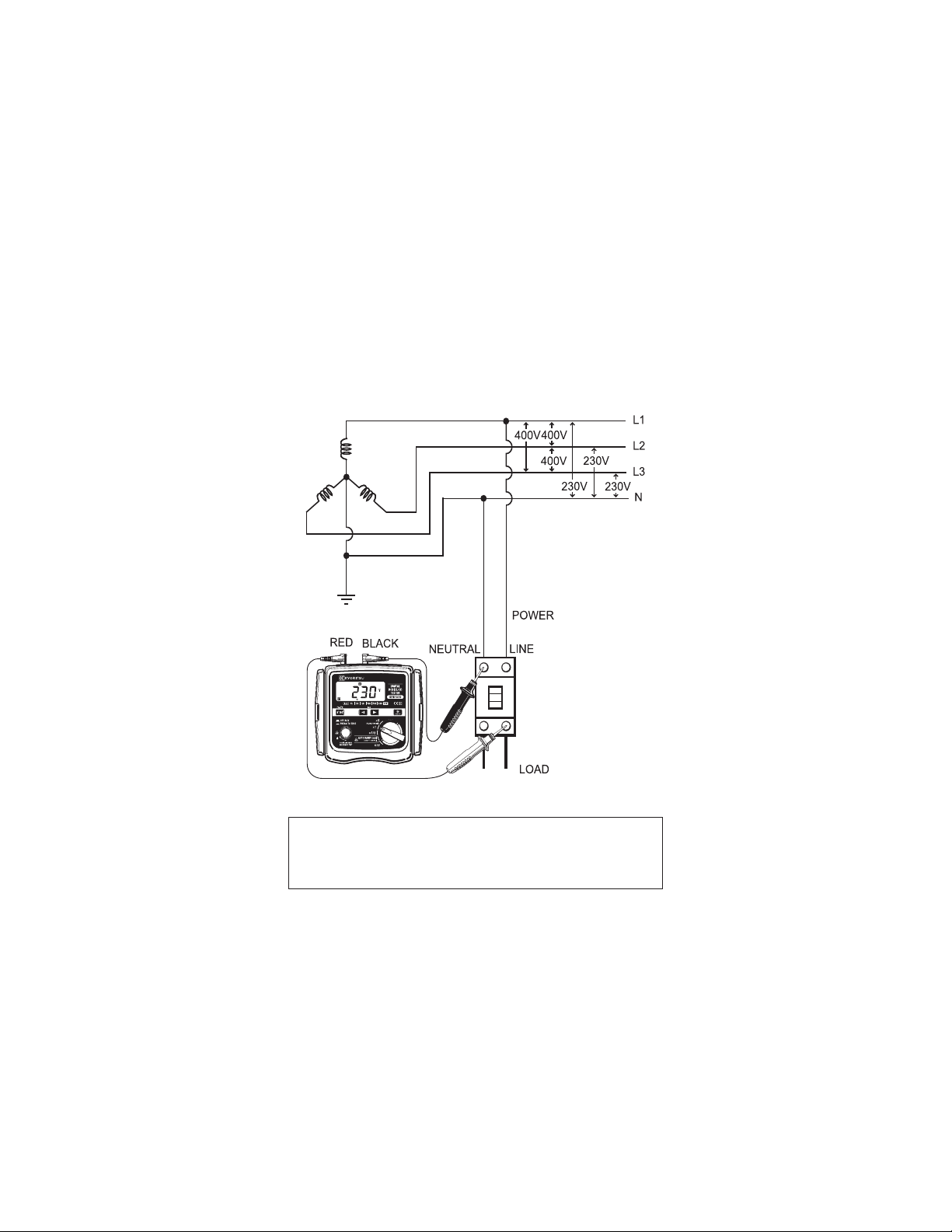
● Neutral - Line
Connect the “PRIMARY” of the C onnector Block to the Neutral of the
power of RCD, and the “SECONDARY” of the Connector Block to the Line
of the load of RCD.
Fig. 7
DANGER
This instrument is designed to measure the earth-to-line voltage 90 ~
264V and the line-to-line voltage up to 440V (50/60Hz). Do not exceed
the maximum allowable input of any measuring range.
Find Quality Products Online at: sales@GlobalTestSupply.com
www.GlobalTestSupply.com
16
Page 19

● Line - Line
Connect the “PRIMARY” of the Connector Block to L2 of the power of
RCD, and the “SECONDARY” of the Connector Block to L1 of the load of
RCD.
Fig. 8
DANGER
This instrument is designed to measure the earth-to-line voltage 90 ~
264V and the line-to-line voltage up to 440V (50/60Hz). Do not exceed
the maximum allowable input of any measuring range.
Find Quality Products Online at: sales@GlobalTestSupply.com
www.GlobalTestSupply.com
17
Page 20

● Earth - Line
Co nne ct the “P R IM A RY” of the C on n ec tor B lo ck to Ear t h, a nd t he
“SECONDARY” of the Connector Block to Line of the load of RCD.
Connection using Earth
Lea kage cu rrent s may flow to RCD (A),
which is installed in the power supply of the
RCD (B) under test, when current flows to
Fig. 9
Extra caution should be taken when applying current to EARTH for tests
since the other RCDs (see Fig.10) may operate and damage the devices
connected to the instrument and cause accidents.
the EARTH; so RCD (A) may trip as well.
Fig. 10
DANGER
8-5 Operating time
Trip ping ti me is t he time needed by the RCD to
operating current of IΔn. The standard values of tripping time are defined by
IEC 61009 and IEC 61008 are listed in the table below for IΔn and 5IΔn.
Type of RCD IΔn (x1) 5IΔn (x5)
General(G)
Selective(S)
300ms
max allowed value
500ms
max allowed value
130ms
min allowed value
18
tri p at a rate d residual
40ms
max allowed value
150ms
max allowed value
50ms
min allowed value
Find Quality Products Online at: sales@GlobalTestSupply.com
www.GlobalTestSupply.com
Page 21

9. Battery Replacement
DANGER
● Do not open the Battery Cover if the instrument is wet.
● Never replace the batteries during measurements. Set the Function
swit ch to the OFF positi on and disconnect the test leads from the
instrument, when replacing batteries, in order to preve nt electrical
shocks.
● Do not mix new and old batteries.
● In st all bat ter ie s in the ori entat io n as shown insi de the bat ter y
compartment, observing correct polarity.
1. Set the Function switch to the OFF position, and disconnect the Test leads
from the Connector Block.
Loosen 2 pcs of Battery Cover fixing screws, and remove the Battery Cover.
2.
3. Replace all 8 pcs of batteries . Ins tall new batte ries observing correc t
polarity. Battery : R6P (size AA) x 8 pcs
4. Install the Battery Cover, and tighten up the screws.
CAUTION
Fig. 11
19
Find Quality Products Online at: sales@GlobalTestSupply.com
www.GlobalTestSupply.com
Page 22

10. Strap Belt Assembly
Correct assembly is shown in Fig.12. By hanging the instrument round
the neck, both hand let free for testing.
Fig. 12
Pass the Strap belt down through
the si de pan el of the main bod y
from the top, and up thr oug h the
slo ts of the Pro be case from the
bottom.
Pass the Strap through the buckle,
ad ju st th e strap for le ngth and
secure.
20
Find Quality Products Online at: sales@GlobalTestSupply.com
www.GlobalTestSupply.com
 Loading...