

Page 1

Instruction Manual
High Voltage Digital Insulation Tester
KEW 3128
Find Quality Products Online at: sales@GlobalTestSupply.com
www.GlobalTestSupply.com
Page 2

Contents KEW3128
Contents
Contents ・・・・・・・・・・・・・・・・・・・・・・・・・・・・・・・・・・・・・・・・・・・・・・・・・・・・・・・・・・・・ 2
1. Safety Warnings ・・・・・・・・・・・・・・・・・・・・・・・・・・・・・・・・・・・・・・・・・・・・・・・・・・・4
2. Feature ・・・・・・・・・・・・・・・・・・・・・・・・・・・・・・・・・・・・・・・・・・・・・・・・・・・・・・・・・・・ 7
3. Specification ・・・・・・・・・・・・・・・・・・・・・・・・・・・・・・・・・・・・・・・・・・・・・・・・・・・・・・ 9
4. Instrument Layout ・・・・・・・・・・・・・・・・・・・・・・・・・・・・・・・・・・・・・・・・・・・・・・・・ 16
4. 1 FRONT VIEW ・・・・・・・・・・・・・・・・・・・
4. 2 SIDE PANEL ・・・・・・・・・・・・・・・・・・・・・・・・・・・・・・・・・・・・・・・・・・・・・・・・・・18
4. 3 TEST LEADS ・・・・・・・・・・・・・・・・・・・・・・・・・・・・・・・・・・・・・・・・・・・・・・・・・ 19
4. 4 HARD CASE ・・・・・・・・・・・・・・・・・・・・・・・・・・・・・・・・・・・・・・・・・・・・・・・・・・19
5. Preparation for Measurement・・・・・・・・・・・・・・・・・・・・・・・・・・・・・・・・・・・・・・20
5. 1 CHECKING THE BATTERY VOLTAGE ・・・・・・・・・・・・・・・・・・・・・・・・・・・20
5. 2 TEST LEAD CONNECTION・・・
6. Measurement ・・・・・・・・・・・・・・・・・・・・・・・・・・・・・・・・・・・・・・・・・・・・・・・・・・・・21
6. 1 BASIC OPERATION ・・・・・・・・・・・・・・・・・・・・・・・・・・・・・・・・・・・・・・・・・・・21
6.1.1 How to start measurements ・・・・・・・・・・・・・・・・・・・・・・・・・・・・・・・・・・21
6.1.2 Steps for Measurements ・・・・・・・・・・・・・・・・・・・・・・・・・・・・・・・・・・・・・23
6.1.3 Setting for Measurement ・・・・・・・・・・・・・・・・・・・・・・・・・・・・・・・・・・・・・30
6.1.4 Graph Ope
6.1.5 Menu・・・・・・・・・・・・・・・・・・・・・・・・・・・・・・・・・・・・・・・・・・・・・・・・・・・・・・37
6.1.6 Filter Mode・・・・・・・・・・・・・・・・・・・・・・・・・・・・・・・・・・・・・・・・・・・・・・・・・41
6.1.7 Save Data ・・・・・・・・・・・・・・・・・・・・・・・・・・・・・・・・・・・・・・・・・・・・・・・・・ 42
6.1.8 Clock Setting ・・・・・・・・・・・・・・・・・・・・・・・・・・・・・・・・・・・・・・・・・・・・・・・47
6.1.9 Demo Mode ・・・・・・・・・・・・・・・・・・・・・・・・・・・・・・・・・・・・・・・・・・・・・・・・47
6. 2 INSULAT
6. 3
6.3.1 Setting Item ・・・・・・・・・・・・・・・・・・・・・・・・・・・・・・・・・・・・・・・・・・・・・・・・ 49
6.3.2 Measured Result ・・・・・・・・・・・・・・・・・・・・・・・・・・・・・・・・・・・・・・・・・・・49
6. 4
6.4.1 Polarization Index ・・・・・・・・・・・・・・・・・・・・・・・・・・・・・・・・・・・・・・・・・・・50
6.4.2 How to measure PI・・・・・・・・・・・・・・・・・・・・・・・・・・・・・・・・・・・・・・・・・・50
IR MEASUREMENT ・・・・・・・・・・・・・・・・・・・・・・・・・・・・・・・・・・・・・・49
PI MEASUREMENT (POLARIZATION INDEX) ・・・・・・・・・・・・・・・50
ration ・
ION DIAGNOSIS TESTS ・・・・・・・・・・・・・・・・・・・・・・・・・・・・・・・48
・・・・・・・・・・・・・・・・・・・・・・・・・・・・・・・・・・・・・・・・・・・33
・・・・・・・・・・・・・・・・・・・・・・・・・・・・・・1
・・・・・・・・・・・・・・・・・・・・・・・・・・・・・・・・・・2
6
0
2 KEW3128
Find Quality Products Online at: sales@GlobalTestSupply.com
www.GlobalTestSupply.com
Page 3
KEW3128 Contents
6.4.3 Measured Result ・・・・・・・・・・・・・・・・・・・・・・・・・・・・・・・・・・・・・・・・・・・53
6. 5
6.5.1 Dielectric Absorption Ratio ・・・・・・・・・・・・・・・・・・・・・・・・・・・・・・・・・・・54
6.5.2 How to measure DAR ・・・・・・・・・・・・・・・・・・・・・・・・・・・・・・・・・・・・・・・ 55
6.5.3 Measured Result ・・・・・・・・・・・・・・・・・・・・・・・・・・・・・・・・・・・・・・・・・・・57
6. 6
6.6.1 Dielectric Discharge ・・・・・・・・・・・・・・・・・・・・・・・・・・・・・・・・・・・・・・・・・58
6.6.2 How to measure DD・・・・・・・・・・・・・・・・・・・・・・・・・・・・・・・・・・・・・・・・・59
6.6.3 Measured Result ・・・・・・・・・・・・・・・・・・・・・・・・・・・・・・・・・・・・・・・・・・・61
6. 7
6.7.1 Step Voltage ・・・・・・・・・・・・・・・・・・・・・・・・・・・・・・・・・・・・・・・・・・・・・・・62
6.7.2 Measurement Setting Items ・・・・・・・・・・・・・・・・・・・・・・・・・・・・・・・・・・62
6.7.3 Measured Result ・・・・・・・・・・・・・・・・・・・・・・・・・・・・・・・・・・・・・・・・・・・64
6. 8 MEASUREMENT SCREEN ・・・・・・・・・・・・・・・・・・・・・・・・・・・・・・・・・・・・・65
6. 9 CAPACITANCE MEASUREMENT ・・・・・・・・・・・・・・・・・・・・・・・・・・・・・・・ 68
6.9.1 Mea
6. 10
6.10.1 Measurement Screen ・・・・・・・・・・・・・・・・・・・・・・・・・・・・・・・・・・・・・・69
6. 11 OTHER FUNCTIONS ・・・・・・・・・・・・・・・・・・・・・・・・・・・・・・・・・・・・・・・・・70
6.11.1 Use of Guard Terminal ・・・・・・・・・・・・・・・・・・・・・・・・・・・・・・・・・・・・・・ 70
6.11.2 Backlight Function ・・・・・・・・・・・・・・・・・・・・・・・・・・・・・・・・・・・・・・・・・71
6.11.3 Auto-power-off function ・・・・・・・・・・・・・・・・・・・・・・・・・・・・・・・・・・・・・7
7
. Battery Charging and Replacement ・・・・・・・・・・・・・・・・・・・・・・・・・・・・・・・・72
7. 1 HOW TO CHARGE BATTERY ・・・・・・・・・・・・・・・・・・・・・・・・・・・・・・・・・・72
7. 2 HOW TO REPLACE BATTERY ・・・・・・・・・・・・・・・・・・・・・・・・・・・・・・・・・・73
8. Communication Function/ Supplied Software ・・・・・・・・・・・・・・・・・・・・・・・75
8. 1 HOW TO INSTALL THE SOFTWARE ・・・・・・・・・・・・・・・・・・・・・・・・・・・・ 76
8. 2 HOW TO START KEW WINDOWS FOR KEW3128 ・・・・・・・・・・・・・・80
9. Ac
9. 1 METAL PARTS FOR LINE PROBE, AND REPLACEMENT ・・・・・・・・・81
10.Disposing the Product ・・・・・・・・・・・・・・・・・・・・・・・・・・・・・・・・・・・・・・・・・・・82
DAR MEASUREMENT (DIELECTRIC ABSORPTION RATIO) ・54
DD MEASUREMENT (DIELECTRIC DISCHARGE) ・・・・・・・・・・・58
SV MEASUREMENT (STEP VOLTAGE) ・・・・・・・・・・・・・・・・・・・・ 62
surement Screen ・
VOLTAGE MEASUREMENT ・・・・・・・・・・・・・・・・・・・・・・・・・・・・・・69
cessories ・
・・・・・・・・・・・・・・・・・・・・・・・・・・・・・・・・・・・・・・・・・・・・・・・・・・・・・81
・・・・・・・・・・・・・・・・・・・・・・・・・・・・・・・・・・・・・・68
1
KEW3128 3
Find Quality Products Online at: sales@GlobalTestSupply.com
www.GlobalTestSupply.com
Page 4

1. Safety Warnings KEW3128
1. Safety Warnings
○
This instrument has been designed, manufactured and tested according to IEC
61010: Safety requirements for Electronic Measuring apparatus, and delivered
in the best condition after passing quality control tests. This instruction manual
contains warnings and safety rules which have to be observed by the user to ensure
safe operation of the instrument and to maintain it in safe condition. Therefore,
read through these operating instructions before using the instrument.
# WARNING
● This instrument outputs high voltages. Read through and understand the
instructions contained in this manual before using the instrument.
● Keep the manual at hand to enable quick reference whenever necessary.
● The instrument is to be used only in its intended applications.
● Understand and follow all the safety instructions contained in the manual.
It is essential that the above instructions are adhered to.
Failure to follow the above instructions may cause injury, instrument damage
and/or damage to equipment under test.
○ The symbol # indicated on the instrument, means that the user must refer to
the related parts in the manual for safe operation of the instrument. It is essential
to read the instructions wherever the # symbol appears in the manual.
# DANGER : is reserved for conditions and actions that are likely to cause
serious or fatal injury.
# WARNING : is reserved for conditions and actions that can cause serious
or fatal injury.
# CAUTION : is reserved for conditions and actions that can cause injury
or instrument damage.
4 KEW3128
Find Quality Products Online at: sales@GlobalTestSupply.com
www.GlobalTestSupply.com
Page 5

KEW3128 1. Safety Warnings
# DANGER
● Put a pair of insulated gloves and use this instrument.
● Never make measurement on a circuit in which the electrical potential
exceeds AC/DC600V.
● Do not attempt to make measurement in the presence of flammable
gasses. Otherwise, the use of the instrument may cause sparking, which
can lead to an explosion.
● Never attempt to use the instrument if its surface or your hand are wet.
● Be careful not to short-circuit the power line with the metal part of the test
leads when measuring voltage. It may cause personal injury.
● Do not exceed the maximum allowable input of any measuring range.
● Do not press the Test Button without test leads connected to the
instrument.
● Never open the Battery Compartment Cover while making measurement.
● Do not touch the circuit under test when measuring insulation resistance or
right after a measurement. You may get an electric shock by a test voltage.
● Stop a measurement if contamination or carbonization which may impair
insulation characteristics is found on the test leads or around the terminals.
● Do not repeat short-circuiting/ opening of test leads intentionally during
insulation resistance measurements. Otherwise, measurements may be
ceased or LCD may become blank due to a malfunction of the instrument.
Aerial discharges occur at the tips of test leads when short-circuiting and
opening the test leads; excessive discharges may impair the performance
of the instrument.
# WARNING
● Never attempt to make any measurement if any abnormal conditions are
noted, such as broken case and exposed metal parts.
● Do not rotate the Range Switch with the test leads connected to the equipment
under test.
●
Do not install substitute parts or make any modification to the instrument. Return
the instrument to Kyoritsu or your distributor for repair or re-calibration.
● Do not try to replace battery if the surface of the instrument is wet.
● Be sure to insert the plug into the terminal firmly when using test leads.
● Make sure to power off the instrument when opening the Battery Compartment
Cover for battery replacement.
KEW3128 5
Find Quality Products Online at: sales@GlobalTestSupply.com
www.GlobalTestSupply.com
Page 6

1. Safety Warnings KEW3128
# CAUTION
● Always make sure to set the Range Switch to the appropriate position
before making measurement.
● Be sure to set the Range Switch to the OFF position after use and
remove the test leads. When the instrument will not be in use for a long
period, place it in storage after removing the battery. Instructions how
to remove a battery are described at Clause 7. Battery Charging and
replacement (=>P.72).
● Do not expose the instrument to the direct sun, high temperature and
humidity or dewfall.
● Use a cloth dipped in water or neutral detergent for cleaning the instrument.
Do not use abrasives or solvents.
● When this instrument is wet, please store it after it dries.
● Remove a battery from the instrument and pack it carefully at the time of
transportation.
Symbol
#
CAT. Ⅳ
6 KEW3128
Danger of possible electric shock
Instrument with double or reinforced insulation
DC
AC
Earth terminal
Must refer to the Instruction Manual to protect humans and devices
The circuit from the service drop to the service entrance, and to the
power meter and primary overcurrent protection device (distribution
panel)
Find Quality Products Online at: sales@GlobalTestSupply.com
www.GlobalTestSupply.com
Page 7

KEW3128 2. Feature
2. Feature
KEW3128 is a digital high voltage insulation resistance tester with 6-range:
500V, 1000V, 2500V, 5000V, 10000V and 12000V, and can measure up
to 35TΩ. Fine adjustment of voltage setting at each Range is available.
Measured results can be saved in the internal memory; they can be transferred
to a PC via a special USB cord. Measuring data can also be transferred to a
PC in real-time.
● Designed to meet following safety standards:
IEC 61010-1 CAT.IV 600V
● Insulation Resistance Measurement
Test Voltage 12kV (max), Resistance 35TΩ (max),
Short-Circuit Current 5mA (max)
● Insulation Diagnosis Tests
Values of Polarization Index (PI), Dielectric Absorption Ratio (DAR) and
Dielectric Discharge (DD) are displayed automatically, and measurements
of Step Voltage (SV), Leakage Current and Capacitance can be performed.
* Further details of Insulation Diagnosis Test is described in clause
6. 2 (=>P.48).
● Saving the Measured Data
The internal memory can store 32 files (max).
Use of Print Screen Function enables save of screenshots.
● Dual Power Supply
Lead storage battery (12V, 5Ah) should be used for KEW3128. In the
event of interruption, while operating with AC power supply, power to the
instrument is automatically restored by the battery in the instrument.
KEW3128 7
Find Quality Products Online at: sales@GlobalTestSupply.com
www.GlobalTestSupply.com
Page 8

2. Feature KEW3128
● Large Display
5.7-inch (320 x 240 dots)
● Graph Display
Varia tions in insulati on resistan ces and leaka ge cur rents under
measurements are displayed as graphs.
When a measurement period exceeds 90 min (IR measurement only),
90min or later portion of the measured result isnt displayed on a graph.
● Application
Data in the internal memory or measuring in real-time can b
a PC via a special USB adapter. The supplied software facilitates setting of
the instrument and data analysis.
● Live Circuit Warning
LIVE circuit warning symbols plus audible warning
● Auto Discharge Function
When insulation resistance like a capacitive load is measured, electric
charges stored in capacitive circuits are automatically discharged after
measuring. Discharge can be checked with a voltage monitor.
e transferred to
● Backlight Function
Backlight function to facilitate working at dimly illuminated location or at
nighttime work.
● Auto-Power-Off Function
To prevent the instrument being left powered on and conserve battery
power, the instrument automatically turns off approx. 10 min after the last
switch operation.
● Filter Function
KEW3128 provides 3 kinds of Filter functions to alleviate fluctuations in
readings. Details of Filter function are described at 6.1.6 Filter Mode
(=> P.41).
8 KEW3128
Find Quality Products Online at: sales@GlobalTestSupply.com
www.GlobalTestSupply.com
Page 9

KEW3128 3. Specification
3. Specification
● Applicable Standards:
IEC61010-1 CAT.IV 600V Pollution Degree2
IEC61010-031 For Hand-held Probe Assemblies
IEC61326 EMC Standard for electrical equipment for
measurement, control and laboratory use
IEC60529 IP64 (with the Bottom Case closed)
CISPR22, 24
KEW3128 9
Find Quality Products Online at: sales@GlobalTestSupply.com
www.GlobalTestSupply.com
Page 10

3. Specification KEW3128
● Measuring Range and Accuracy (under 23±5ºC and 45 – 75%RH)
【Insulation Resistance Tester】
Rated Voltage
Max value 500GΩ 1.00TΩ 2.50TΩ 5.00TΩ 35.0TΩ 35.0TΩ
Accuracy
Display Range
Out-of-
range
display
Short-circuit
Lower
limit
Upper
limit
current
Leakage
current
Output
current
500V 1000V 2500V 5000V 10000V 12000V
400k to 50GΩ
±5%rdg±3dgt
50G to 500GΩ
±20%rdg
* Accuracy is
not guaranteed
with setting of
250V or less.
400k to 999k
1.00M to 9.99M
10.0M to 99.9M
100M to 999M
1.00G to 9.99G
10.0G to 99.9G
100G to 600G
<400kΩ <800kΩ <2.00MΩ <4.00MΩ <8.00MΩ <8.00MΩ
<1.8mA
>600GΩ >1.20TΩ >3.00TΩ >6.00TΩ >35.0TΩ >35.0TΩ
1mA or more,
1.2mA or less
under a load of
0.5MΩ
* Should be
500V or more
800k to 100GΩ
±5%rdg±3dgt
100G to 1TΩ
±20%rdg
800k to 999k
1.00M to 9.99M
10.0M to 99.9M
100M to 999M
1.00G to 9.99G
10.0G to 99.9G
100G to 999G
1.00T to 1.20T
<1.65mA <1.65mA <1.65mA <0.263mA <0.315mA
1mA or more,
1.2mA or less
under a load of
1MΩ
2M to 250GΩ
±5%rdg±3dgt
250G to 2.5TΩ
±20%rdg
2.00M to 9.99M
10.0M to 99.9M
100M to 999M
1.00G to 9.99G
10.0G to 99.
1
00G to 999G
1.00T to 3.00T
1mA or more,
1.2mA or less
under a load of
2.5MΩ
4M to 500GΩ
±5%rdg±3dgt
500G to 5TΩ
±20%rdg
4.00M to 9.99M
10.0M to 99.9M
100M to 999M
1.00G to 9.99G
10.0G to 99.9G
9G
100G to 999G
1.00T to 6.00T
Max 5.0mA
0.01nA 〜
1mA or more,
1.2mA or less
under a load of
5MΩ
8M to 1TΩ
±5%rdg±3dgt
1T to 10TΩ
±20%rdg
10T t
o 35TΩ
Va
lues are
displayed, but
accuracy isnt
guaranteed.
8.00M to 9.99M
10.0M to 99.9M
100M to 999M
1.00G to 9.99G
10.0G to 99.9G
100G to 999G
1.00T to 9.99T
10.0T to 35.0T
0.15mA or
more, 0
o
r less under a
load of 10MΩ
8M to 1TΩ
±5%rdg±3dgt
1T to 10TΩ
±20%rdg
10T to 35TΩ
Values are
displayed, but
accuracy isnt
guaranteed.
8.00M to 9.99M
10.0M to 99.9M
100M to 999M
1.00G to 9.99G
10.0G to 99.9G
100G to 999G
1.00T to 9.99T
10.0T to 35.0T
0.15mA or
.25mA
more, 0.25mA
or less under a
load of 12MΩ
Note: The Lower limit value within the Display Range is shown when the test
leads are short-circuited and the Upper limit value within the Display
Range is shown when measured values exceeds the Display Range.
10 KEW3128
Find Quality Products Online at: sales@GlobalTestSupply.com
www.GlobalTestSupply.com
Page 11

KEW3128 3. Specification
【Output Voltage】
Rated Voltage 500V 1000V 2500V 5000V 10000V 12000V
Monitor Accuracy ±10%rdg±20V ±10%rdg±20V ±10%rdg±20V ±10%rdg±20V ±10%rdg±20V ±10%rdg±20V
Output Accuracy 0~+20% 0~+10% 0~+10% 0~+10% -5~+5% -5~+5%
Selectable Range
50~600V
(in steps of 5V)
610~1200V
(in steps of 10V)
1225~3000V
(in steps of 25V)
3050~6000V
(in steps of 50V)
6100~10000V
(in steps of 100V)
10100~12000V
(in steps of 100V)
Incorrect readings are displayed when external AC voltages are applied.
【Graph of Resistance-Output voltage Characteristic】
500V/1 000V/25 00V/500 0V Range
6,000
5,000
4,000
3,000
2,000
Output Voltage (V)
1,000
0
0.0001 0 .001 0.01 0.1 1 1 0 10 0
Insulation Resistance (GΩ)
5000V
2500V
1000V
500V
14,000
12,000
10,000
8,000
6,000
4,000
Output Voltage (V)
2,000
0
0.0001 0.001 0.01 0.1 1 10 100
10kV/12 kV Range
12kV
10kV
Insulation Resistance (GΩ)
Rated current at 500V, 1000V, 2500V, 5000V Ranges : max 1mA or higher
Rated current at 10kV, 12kV Ranges : max 0.5mA
Above graphs show the relations between output voltages and measurement
resistances.
KEW3128 11
Find Quality Products Online at: sales@GlobalTestSupply.com
www.GlobalTestSupply.com
Page 12

3. Specification KEW3128
【Volt Meter】
Range Voltage Test
Measuring Range
Accuracy ±2%rdg±3dgt
【Frequency】
Range Voltage Test
Measuring Range 45.0 ~ 65.0Hz
Accuracy ±0.2Hz
【Ammeter】
Measuring Range
* The output current can throw 5mA. The current that flows by the lower
bound within the range of the resistance measurement is shown in the table
【Insulation Resistance Tester】 of page 10.
When resistance that is lower than the lower bound within the range of
the resistance measurement is measured, the measurement current might
become larger than 2.4mA.
The display in that case becomes >2.40mA".
Minimum resolution 0.01nA
DC Voltage AC Voltage
±30~±600V 30~600V(50/60Hz)
0.00nA〜 2.40mA
(determined by resistance
and voltage values)
Depending on the
effective range of
insulation resistances
【Capacity Meter】
Range 500V ~ 5000V Range 10000V / 12000V Range
Accuracy
* Measurements of capacitance of 0.5μ or more shouldnt be repeated at
10000V/ 12000V Ranges in a short time. (Rough guide: 5 times/ hour)
* A message Noise Error may be displayed on the LCD and a measurement
may be ceased at 10000/12000V Ranges. In this case, select a lower Voltage
Range and test again.
【C
alculated Value】
PI,DAR,DD
Measurement Mode PI DAR DD
Display Range 0.00 ~ 999 0.00 ~ 999 0.00 ~ 999
Computational error ±2dgt ±2dgt ±2dgt
● Electromagnetic compatibility (IEC61000-4-3)
Radio-frequency electromagnetic field
12 KEW3128
5.0nF ~ 50.0μF 5.0nF ~ 1.0μF
±5%rdg±5dgt
= 10V/m : 20times of the specified accuracy
Find Quality Products Online at: sales@GlobalTestSupply.com
www.GlobalTestSupply.com
Page 13

KEW3128 3. Specification
● Operating system Dual integration
● Display
● Low battery warning Battery mark display (in 4 levels)
● Response time approx 30 sec in a range of ±5% of accuracy
● Auto-power-off
● Altitude 2000m or less
● Temperature & humidity
range(guaranteed accuracy)
● Operating temperature &
humidity range
● Storage temperature &
humidity range
● Overload protection AC720V/10 sec.
● Withstand voltage
● Insulation resistance 1000MΩ or more/DC1000V
● Dimension
● Weight
● Power source
320 x 240 dots, 5.7-inch
Monochrome Display
ap prox 60 sec in a range of ±20% of
accuracy (Response time becomes slower
when output voltage becomes lower.)
Power-off function operates when 10 min
pass without any key operatio
23ºC±5ºC/Relative humidity 85% or less
(no condensation)
-10ºC~50ºC/Relative humidity 85% or less
(when operating with an external power
supply, no condensation)
0ºC~40ºC/Relative humidity 85% or less
(when operating with battery, no condensation)
-20ºC~60ºC/Relative humidity 75% or less
(no condensation)
AC8770V : between line terminal and
enclosure /5sec (50/60Hz)
AC6880V : between the measuring
terminal and enclosure /5sec (50/60Hz)
AC2330V : between the power connector
and enclosure /5sec (50/60Hz)
(between electrical circuit and enclosure)
330(L)×410(W)×180(D)mm
(Instrument and Hard case )
approx 9kg (including battery)
(Instrument and Hard case )
Rechargeable Lead storage battery
( PXL-12050:12V 5Ah), AC Power supply
(100V ~ 240V, 50 / 60Hz)
n.
KEW3128 13
Find Quality Products Online at: sales@GlobalTestSupply.com
www.GlobalTestSupply.com
Page 14

3. Specification KEW3128
● Current Consumption (representative values at 12V of battery voltage)
Range 500V 1000V
Short-circuiting the output 2650mA 2300mA
Short-circuiting the output
of rated current
Opening the output 210mA 220mA
Range 2500V 5000V
Short-circuiting the output 1700mA 1600mA
Short-circuiting the output
of rated current
Opening the output 280mA 380mA
Range 10000V 12000V
Short-circuiting the output 1550mA 1550mA
Short-circuiting the output
of rated current
Opening the output 570mA 650mA
1350mA/0.5MΩ 1500mA/1MΩ
1650mA/2.5MΩ 2000mA/5MΩ
500mA/10MΩ 540mA/12MΩ
Range Voltage Test
Measuring voltages 210mA
Range All Ranges
On Stand-by 210mA
Backlight is On Increased by 80mA
14 KEW3128
Find Quality Products Online at: sales@GlobalTestSupply.com
www.GlobalTestSupply.com
Page 15

KEW3128 3. Specification
● Continuous measurement: No limitation (IR measurement mode)
* recorded data and graph are max 90 min.
Max 90 min (SV measurement mode)
Max 60 min (PI/DAR/DD measurement mode)
●
Max current consumption and measurement time while rated currents are maintained.
Condition Current consumption Measurement time
500V / 300kΩ
1000V / 600kΩ
2500V / 2.4MΩ
5000V / 4.8MΩ
10000V / 20MΩ
12000V / 24MΩ
* Current consumption may exceed above values when low resistances,
which influence the output of rated currents, are measured.
* Measurement time (approx 4 hours) described at page 15 and the
Measurement time in above table are the periods tha
battery voltage drops to the lowest level
* It is recommended to charge the battery with reference to 7.1 How to
charge battery described in the manual before stating to use with the
instrument since the battery voltage may be low due to self-discharge.
2100mA
or less
Approx
2 hours
t full-charged
● Accessories Line Probe (MODEL7226)
Line Probe with Alligator Clip (MODEL7227)
Earth Cord (MODEL7224)
Guard Cord (MODEL7225)
C
(MODEL8212 USB)
PC Software
Straight Type Metal Parts (MODEL8029)
Power Cord (MODEL7170)
Instruction Manual
KEW3128 15
ommunication Adapter
Find Quality Products Online at: sales@GlobalTestSupply.com
www.GlobalTestSupply.com
Page 16

4. Instrument Layout KEW3128
4. Instrument Layout
4. 1 Front View
16 KEW3128
Find Quality Products Online at: sales@GlobalTestSupply.com
www.GlobalTestSupply.com
Page 17

KEW3128 4. Instrument Layout
Keys
Keys Details
Print Screen/
Backlight
ESC
ENTER
UP/DOWN
TEST
Range Switch
Shuttle Switch
KEW3128 17
Key
Key
Key
Key
Button
Short press : Turn on/ off the LCD Backlight
Long press : Save the displayed screen as a
(1sec or longer) BMP (bitmap) file.
Cancel a process, or return to the previous screen.
Confirm entries, or move to the next screen.
Move a cursor or alter setting values.
Start measurements.
Power on/off the instrument, or select a
Measurement Range.
Move a cursor or alter setting values.
Find Quality Products Online at: sales@GlobalTestSupply.com
www.GlobalTestSupply.com
Page 18

4. Instrument Layout KEW3128
Connectors
4. 2 Side Panel
ENTERキー
USB Connector
バックライト
Power Connector
ESCキー
Battery Cover
18 KEW3128
Find Quality Products Online at: sales@GlobalTestSupply.com
www.GlobalTestSupply.com
Page 19
KEW3128 4. Instrument Layout
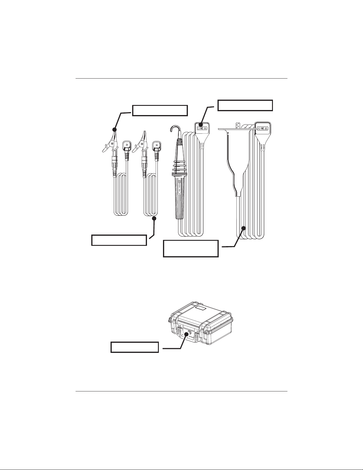
4. 3 Test Leads
Earth Cord (Black)
Guard Cord (Green)
Depending on usage, either Line Probe or Line Probe with Alligator Clip is
connected to the Line terminal.
Line Probe
w/Alligator Clip (red)
Line Probe (red)
4. 4 Hard Case
Regulating valve
Regulating valve is to balance the air pressure in the Case hermetically sealed
and external atmosphere for easy opening/closing of Case lid.
Do not force to turn it or remove it.
KEW3128 19
Find Quality Products Online at: sales@GlobalTestSupply.com
www.GlobalTestSupply.com
Page 20
5. Preparation for Measurement KEW3128
5. Preparation for Measurement
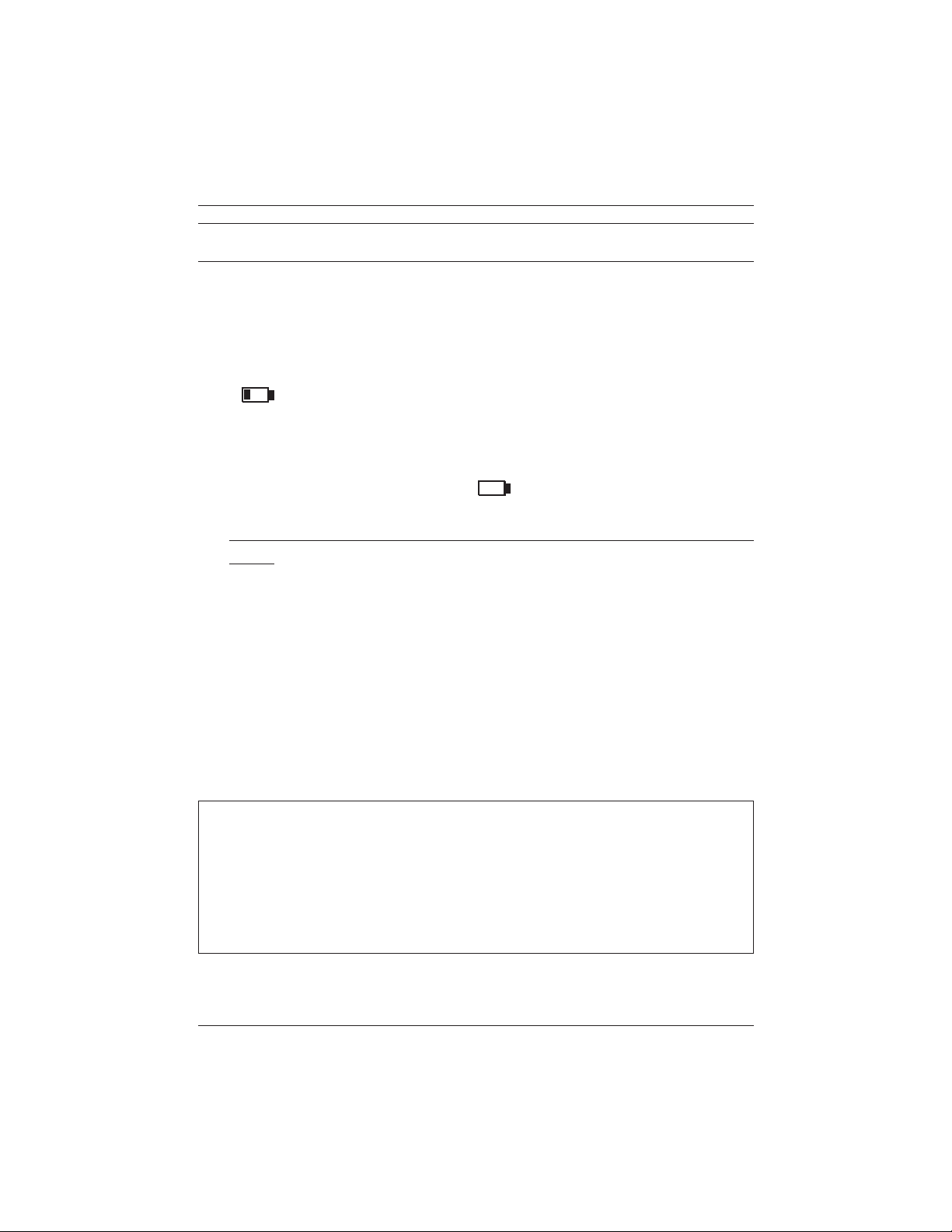
5. 1 Checking the battery voltage
Set the Range Switch to any position other than OFF without connecting
the Power Cord to the Power Connector.
When the Battery Mark shown at the upper right on the LCD is last 1 level
( ), the battery is almost exhausted. Replace or recharge battery
to continue measurements. The instrument operates properly even if
under such a low battery, and such a low battery status may not affect the
accuracy.
When the Battery Mark is vacant ( ), the battery voltage is below the
lower limit of the operating voltage. So the accuracy cannot be guaranteed.
No measurement can be performed even the TEST Button is pressed
down. Refer to Battery Charge and Replacement (=>P.72) and charge or
replace battery.
5. 2 Test Lead Connection
Insert the test lead firmly to the Connector Terminal on the instrument.
Connect the Line Probe (red) or Line Probe with Alligator clip (red) to
the Line Terminal, Earth Cord(black) to the Earth Terminal and Guard
Cord(green) to Guard Terminal. No need to connect Guard Cord when
establishing a guard is not necessary.
Refer toHow to use Guard Terminal(=>P.70) in this manual for further details.
# DANGER
● If the TEST Button is pressed while the Range Switch is at a Range other
than OFF, high voltages may applied to the test leads and you may get
an electric shock.
● Do not connect the Earth Cord (black) nor Guard Cord (green) to the Line
Terminal.
Carefully read through 1. Safety Warnings (P.4) in this manual.
20 KEW3128
Find Quality Products Online at: sales@GlobalTestSupply.com
www.GlobalTestSupply.com
Page 21

KEW3128 6. Measurement
6. Measurement
6. 1 Basic Operation
6.1.1 How to start measurements
Start-up Screen
Setting the Range Switch to any position other than the OFF position
powers on the instrument. Setting the Switch to the OFF position powers
off the instrument.
Following Start-up Screen with Model name and Version info is displayed
when powering on the instrument. Then KEW logo will appear.
* Pressing the Enter Key skips the opening screen.
The Mode Selection Screen appears at the initial operation after
purchase.
The instrument remembers the previous selected mode, and starts with
the mode next time it is powered on.
KEW3128 21
Find Quality Products Online at: sales@GlobalTestSupply.com
www.GlobalTestSupply.com
Page 22
6. Measurement KEW3128
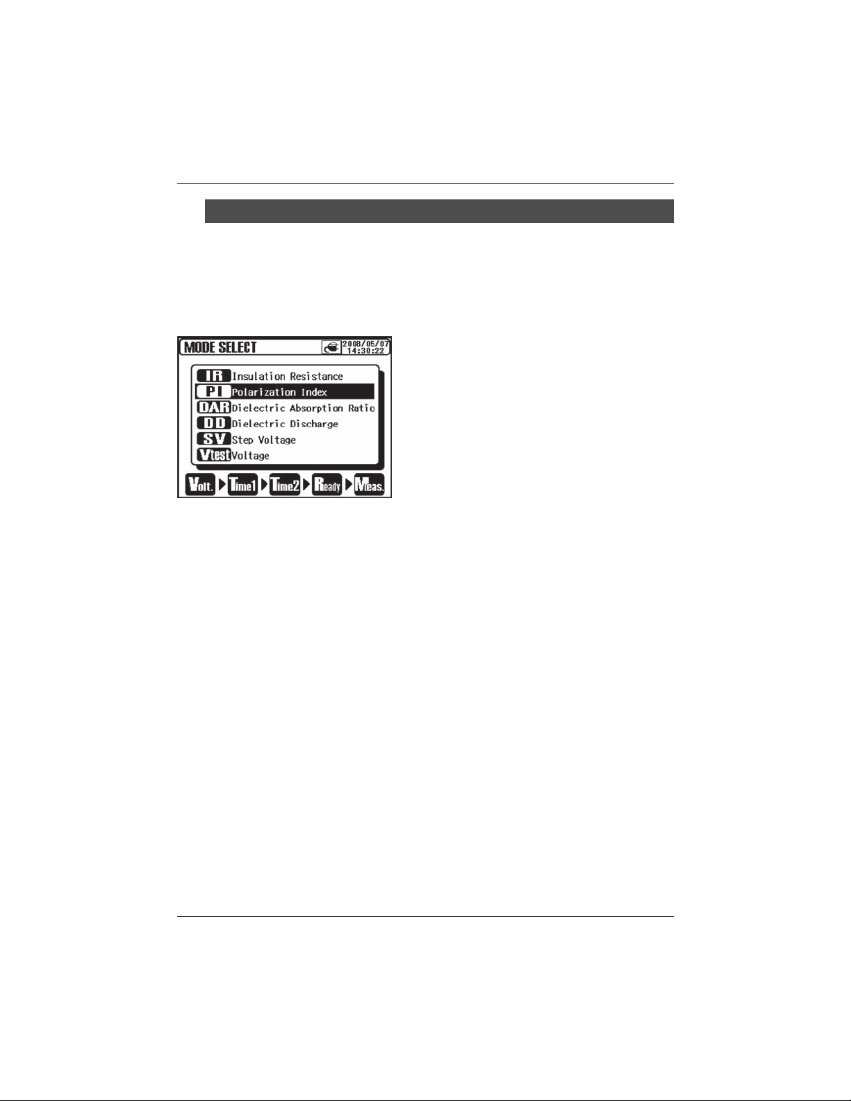
How to select a Measurement Mode
A long press (1 sec or more) of the ESC Key displays the Mode Selection
Screen.
Measurement modes which are selectable on the Model Selection Screen
are mentioned at Insulation Diagnosis test (=>P.48).
Move the cursor with the UP/ DOWN Key
or Shuttle Switch, and confirm the mode
with the ENTER Key.
Then a process from making settings to a
start of measurement is displayed at the
bottom of the LCD. Measurement Modes
can be switched directly from the Menu.
(=>P.37 Menu)
22 KEW3128
Find Quality Products Online at: sales@GlobalTestSupply.com
www.GlobalTestSupply.com
Page 23
KEW3128 6. Measurement
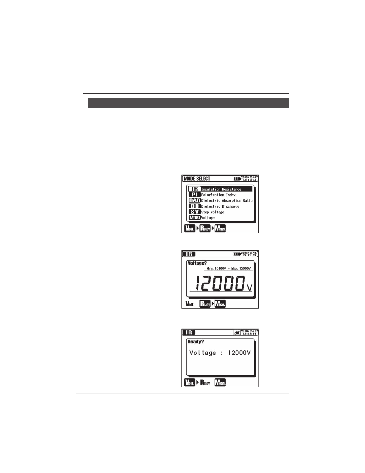
6.1.2 Steps for Measurements
Insulation Resistance Measurement
① Check the voltage which can be applied to the circuit under test,
and set the Range Switch to any desired Voltage Range.
② Select the IR (Insulation Resistance) on the Mode Selection
Screen, and press the ENTER Key.
The instrument gets started with the previously selected mode, and enters
into the stand-by mode.
③ Set a voltage value, and confirm it with the ENTER Key.
④ Confirmation Screen is displayed. Press the ENTER Key and
confirm the value.
KEW3128 23
Find Quality Products Online at: sales@GlobalTestSupply.com
www.GlobalTestSupply.com
Page 24
6. Measurement KEW3128
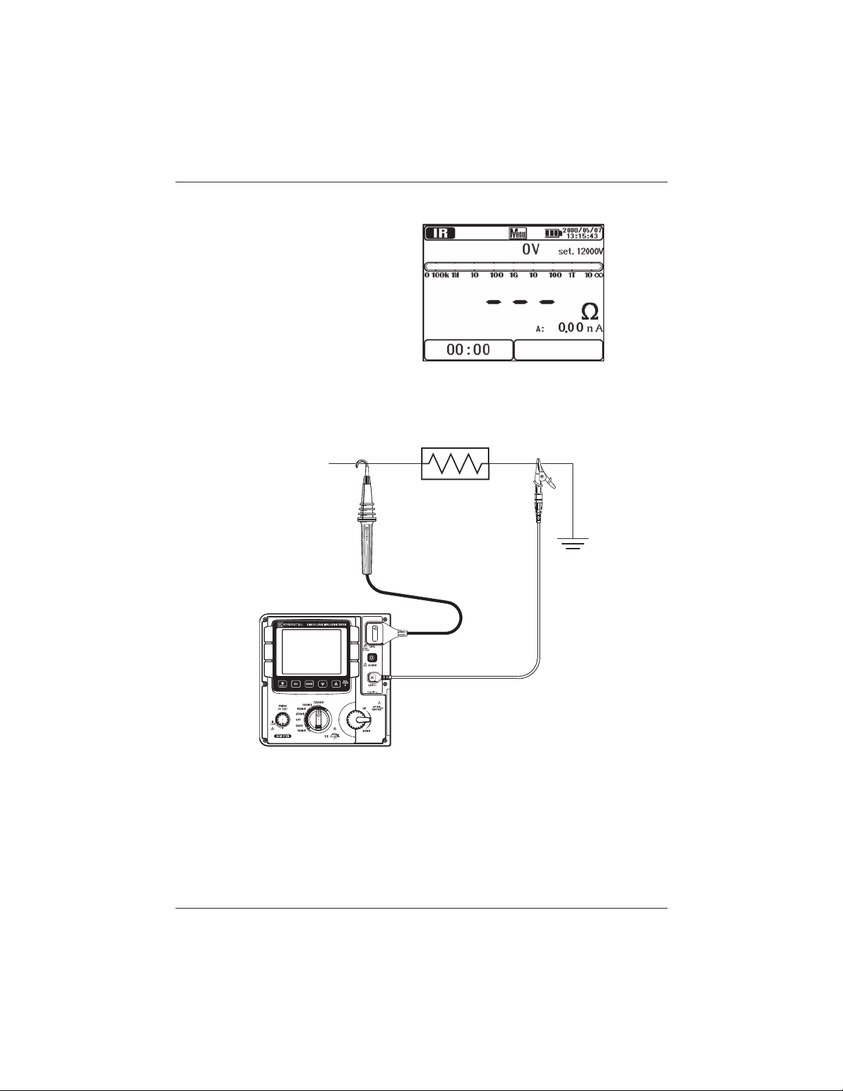
⑤
The instrument enters into stand-by mode when settings are made.
⑥ Connect the Earth Cord (black) to the Earth Terminal of the
circuit under test.
LINE
⑦ Put the tip of the Line Probe (red) to the circuit under test. Then
press the Test Button. The buzzer sounds intermittently during a
measurement.
Press and turn the Test Button clockwise to lock the Button for making
measurements continuously.
The sound of buzzer when a Voltage Range is set to 12kV is special to
give warnings that high voltages more than 10kV is output.
24 KEW3128
Find Quality Products Online at: sales@GlobalTestSupply.com
www.GlobalTestSupply.com
Page 25
KEW3128 6. Measurement
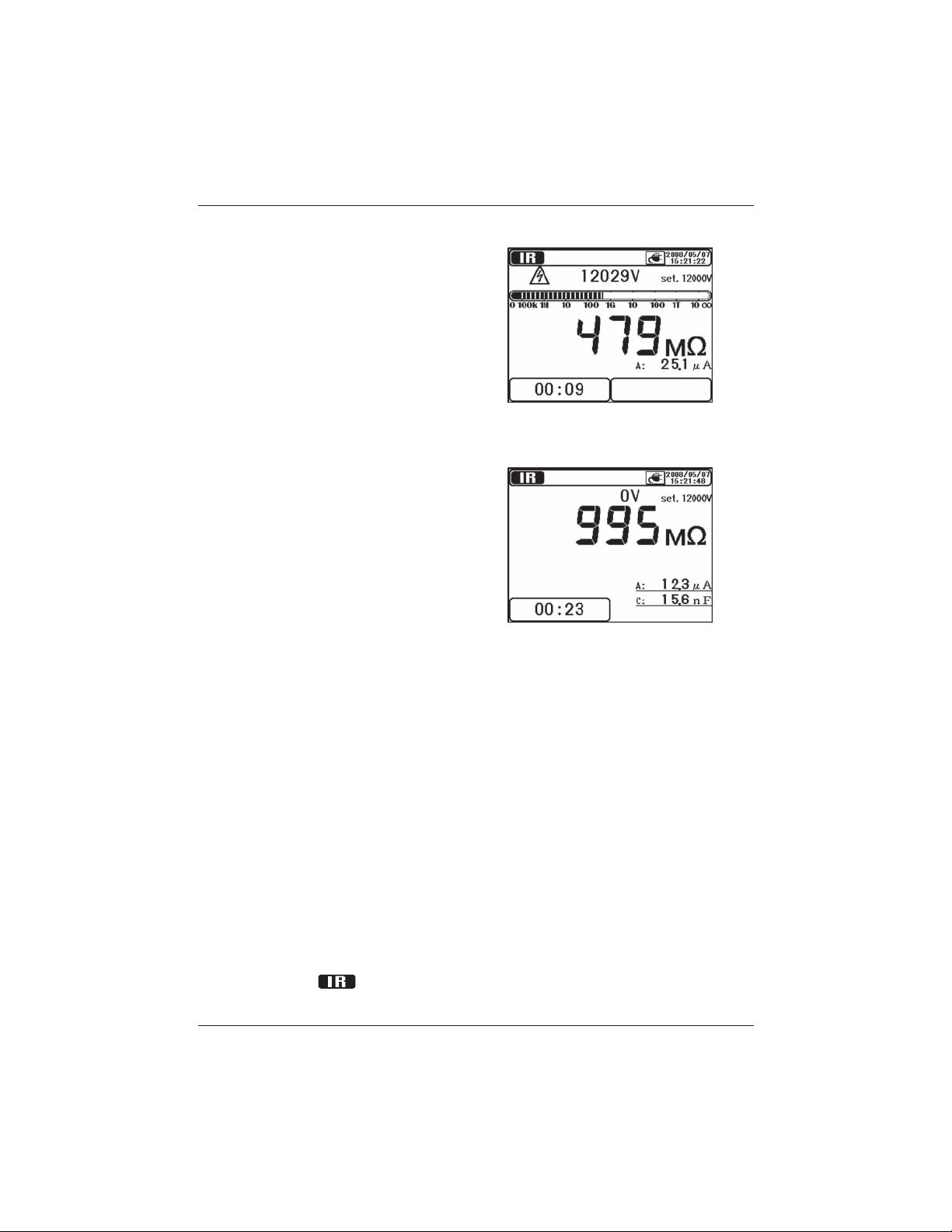
⑧ The measured value will be displayed on the LCD.
⑨ Release the Button to stop the measurement. Then the measured
results will be displayed on the LCD.
Turn the locked Test Button counterclockwise and unlock the Button.
⑩ This instrument has an auto-discharge function. With the test
leads connected to the circuit under test, release the Test button
to discharge capacitance in the circuit after test.
Confirm that the readings on the Voltage monitor becomes 0V.
*
⑪ Set the Range Switch toOFFposition, and remove the test
Next measurement may not be started when the Test Button is pressed
Refer to IR Measurement (=>P.49) and subsequent pages about
KEW3128 25
Do not remove the test leads if the discharging process is not
finished. In case of disconnection of test leads before the finish
the discharging process, reconnect the test leads to the measured
object again and continue the discharge. In this case, a longer
discharge period is required because the internal discharge circuit
doesnt work. Attention should be paid when reconnecting the test
leads in order to limit the possible aerial discharges.
leads from the device under test.
right after when above step 10 is done. In this case, release the Test
Button and wait for a few seconds, and then press the Test Button.
the further details of items displayed at each Measurement mode.
Find Quality Products Online at: sales@GlobalTestSupply.com
www.GlobalTestSupply.com
Page 26

6. Measurement KEW3128
# DANGER
● Do not touch the circuit under test just after finishing a measurement. The
charged potentials may cause electrical shock hazard.
● Do not touch the circuit under test and also not to remove the test leads
until a discharge completes.
● Check with a High Voltage Detector that there is no electrical charge exists
on the circuit under test.
● Be sure to put on a pair of insulated gloves for high voltage.
● Be extremely careful not to get electric shock during insulation resistance
measurements and the Test Button is being pressed as high voltage is
present on the tip of test leads and on the circuit under test continuously.
● Do not make measurement with the Battery Cover removed.
● Do not make measurement when thunder rumbling.
# CAUTION
● When the live circuit warning is indicated or the warning buzzer sounds,
measurements cannot be made even if the Test Button is pressed.
To check the insulation of electric equipments or electric circuits, measure
their insulation resistances with this instrument. Be sure to check the
voltage which can be applied to the equipment under test before making
a measurement.
Measurements automatically stop, when battery voltage becomes too low
to ensure accuracy of readings, while the instrument is operating with a
battery. In this case, the instrument performs auto-discharge and displays
warning for low battery voltage as shown below. Then LCD becomes blank.
26 KEW3128
Find Quality Products Online at: sales@GlobalTestSupply.com
www.GlobalTestSupply.com
Page 27

KEW3128 6. Measurement
A
Note:
* Insulation resistance values of the equipment under test may not be
stable, and the readings on the LCD may be unstable.
* Oscillation sound may be heard during insulation resistance measurement,
but it is not malfunction.
* It takes time to measure a capacitive load.
* Measurements, right after a measurement complete, may not get started
even the Test Button is pressed. In such a case, press the Button in
several seconds later.
* For insulation resistance measurements, normally the output voltage
generated by the instrument is in DC, with the positive pole (+) connected
to the earth terminal of the instrument and the negative pole (-) to the line
terminal of the instrument.
With objects under test connected to earth (ground), the v
by instrument with such polarity, usually permits to read smaller measured
values (so better for safety) comparing with other way round polarity.
* Do not extend and use the test leads; it may affect on measurement
accuracy or impair the safety of this instrument.
* When measuring high resistance higher than 1TΩ, the Part A of the Line
Probe indicated in the below illustration shouldnt be touched with the
things other than the measured object. In case that such a contact is
unavoidable, use something with high insulation resistance like Teflon or
foamed polystyrene, as a cushion.
oltage applied
* When making measurements without connecting the test leads to
anything to be tested, an over-range indication , e.g. >35.0TΩ (at 10kV
or 12kV Range), may not be displayed.
It is likely caused in high humidity environment due to currents leaked at
unexpected points other than the measured objects due to applying high
voltages.
* Proper measurements cannot be made due to influences of variations in
strong magnetic fields or noises caused at discharging energies stored in
KEW3128 27
Find Quality Products Online at: sales@GlobalTestSupply.com
www.GlobalTestSupply.com
Page 28

6. Measurement KEW3128
capacitors or something like this when short-circuiting/ opening the Line –
Earth (Guard) of the test lead during an insulation resistance measurement
is repeated. In this case, Noise Error is displayed on the LCD and further
measurement is ceased. Placing the test leads onto the LCD tends to
cause this phenomenon (indications may be all cleared) ; so do not place
the test leads onto the LCD.
When LCD becomes blank, rotate the Range Switch to the OFF position,
and then set it to any desirable Voltage Range.
* When measuring low resistances (in case that currents larger than
the rated current is output) for a long time, the measured object or
the instrument may become heat and dangerous due to high energy
consumption. So this instrument automatically r
when measuring low resistances. A message Stop measuring is
displayed on the LCD, when low resistances are measured for a long time,
and measurements are stopped.
Temperature inside the instrument is high when Stop measuring is
displayed and measurements are ceased. In this case, please wait at least
30 min to make further measurements.
* The Voltage monitor may indicate 10V to 200V instead of 0V when short-
circuiting the Line Probe and Earth Cord when voltages are output. In this
case, voltages applied to the resistors mounted in the internal measuring
circuit are included and displayed on the LCD.
educe the output voltages
28 KEW3128
Find Quality Products Online at: sales@GlobalTestSupply.com
www.GlobalTestSupply.com
Page 29

KEW3128 6. Measurement
Check of Power Interruption(Voltage Measurements)
# DANGER
● Do not make measurement on a circuit above AC/DC600V(voltage to earth)
to avoid possible electric shock.Do not make a measurement, even if a line
voltage is 600V or less, when a voltage to earth is over 600V.
● When testing installation that has a large current capacity, such as a power
line, be sure to make measurements on the secondary side of a circuit
breaker in order to avoid possible hazard to the user.
● Extra precaution shall be taken to minimize the possibility of shorting the
power line with the metal tip of test lead at voltage measurement. It may
cause personal injury.
● Do not make measurement with the Battery Cover removed.
Voltage can be measured by selecting the Vtest (Voltage) on the Mode
selection screen. (=>P.22 How to select a Measurement Mode) No need
to press the Test Button to start a measurement.
This instrument is equipped with AC/DC auto-detect circuit, and can
measure DC voltages. At a DC voltage measurement, when applying
positive voltage to the Line Probe (red), positive values are displayed on
the LCD.
① Turn off the Circuit Breaker of
the circuit under test.
②
③
Refer to Voltage Measurement (=>P.69) for further details on the
KEW3128 29
Connect the Earth Cord (black) to
the earth side of the circuit under
test and the Line Probe (red) to
the line side respectively.
The voltage displayed on the LCD
shall be Lo V. If not, voltages
of 30V or more is applied on
the circuit under test. Check
the circuit under test again and
confirm that the Circuit Breaker is turned off.
indications on the LCD.
Find Quality Products Online at: sales@GlobalTestSupply.com
www.GlobalTestSupply.com
Page 30

6. Measurement KEW3128
6.1.3 Setting for Measurement
Select a mode at Measurement Mode Selection Screen, and make
settings for measurements.
Setting items are displayed on the LCD one
by one.
Use the UP/D OWN Key and Shuttl e
Switch and alter the values, and press the
ENTER Key to confirm the entry and move
to the next setting item. Pressing the ESC
Key returns to the previous item. All the
set items are displayed on the LCD once
settings are done. Press the ENTER Key
at a Confirmation Screen to get the instrument entered into a stand-by mode.
A process from making the setting to a start of measurement is displayed
at the bottom of the LCD with the corresponding stage mark flashing. The
Measurement Setting Screen is also accessible from the Menu. (=>P.37 Menu)
30 KEW3128
Find Quality Products Online at: sales@GlobalTestSupply.com
www.GlobalTestSupply.com
Page 31

KEW3128 6. Measurement
Setting of Output Voltage
Output voltage can be selected with the Range Switch first, and then fine
adjusted with the Cursor Keys. Selected voltage values cannot be altered
while making measurements or outputting voltages.
The table below shows the selectable range of voltages and step values
at each Measurement Range.
Range Step Min Max
500V 5V 50V 600V
1000V 10V 610V 1200V
2500V 25V 1225V 3000V
5000V 50V 3050V 6000V
10000V 100V 6100V 10000V
12000V 100V 10100V 12000V
KEW3128 31
Find Quality Products Online at: sales@GlobalTestSupply.com
www.GlobalTestSupply.com
Page 32

6. Measurement KEW3128
Setting of Measurement Period
TIME1 & 2 for PI/DAR Measurements, TIME for DD Measurements and
Step time for SV Measurements can be altered respectively.
The table below shows the step values for each selectable period.
Selectable period Step
15 sec – 1 min 1 sec
1 min – 10 min 30 sec
10 min – 60 min 1 min
The lower bound value of each measurement mode at the set time is 15
seconds.
32 KEW3128
Find Quality Products Online at: sales@GlobalTestSupply.com
www.GlobalTestSupply.com
Page 33
KEW3128 6. Measurement
6.1.4 Graph Operation
Selecting the Time Axis ZOOM or Measured Value Axis
ZOOM from the ENTER Menu (=>P.37) on the Graph Display Screen
enters into Graph ZOOM Mode. In this mode, zooming and scrolling of
graphs are available. A short press (within 1 sec) of the ESC Key in the
Graph ZOOM Mode quits the Graph ZOOM Mode and returns to a normal
Graph Display Screen. The instrument keeps the zoomed percentage and
the scrolled condition.
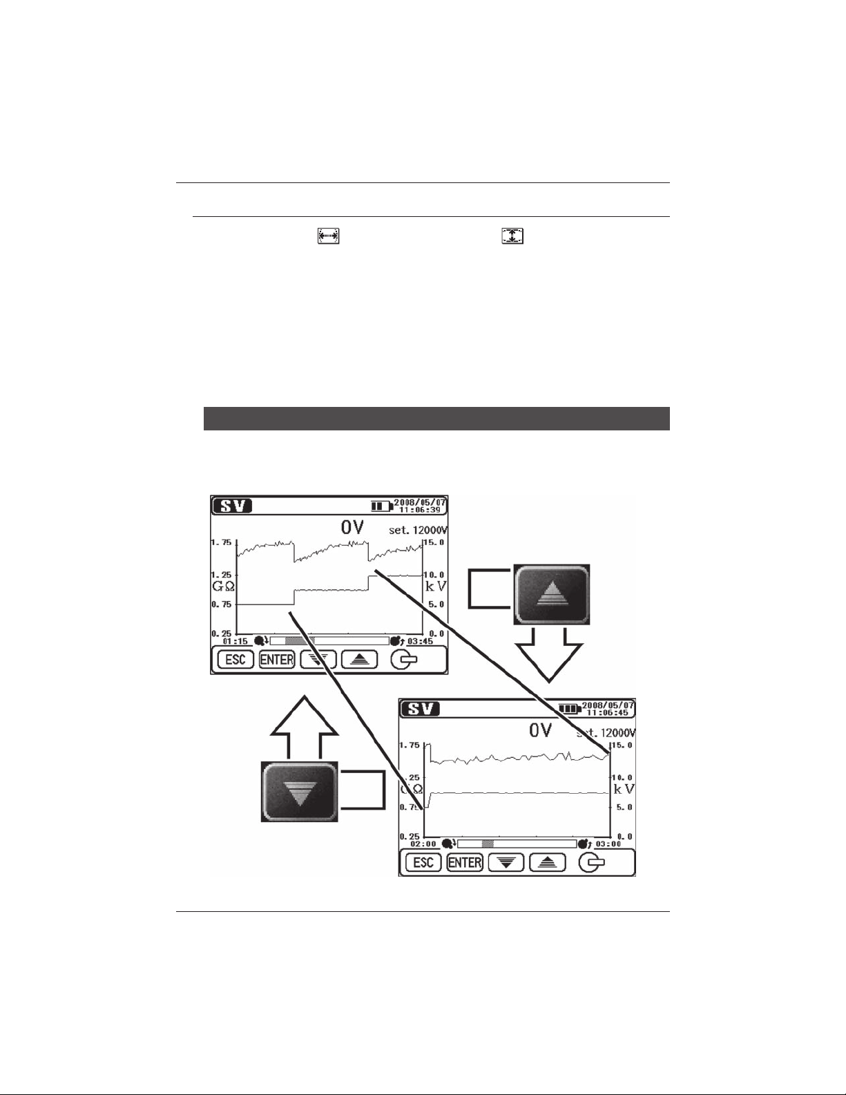
Zooming in/ out of graphs
Use the UP Key to zoom in the graph and the DOWN Key to zoom out.
The Voltage Axis at SV measurements is fixed and cannot be changed.
KEW3128 33
Find Quality Products Online at: sales@GlobalTestSupply.com
www.GlobalTestSupply.com
Page 34
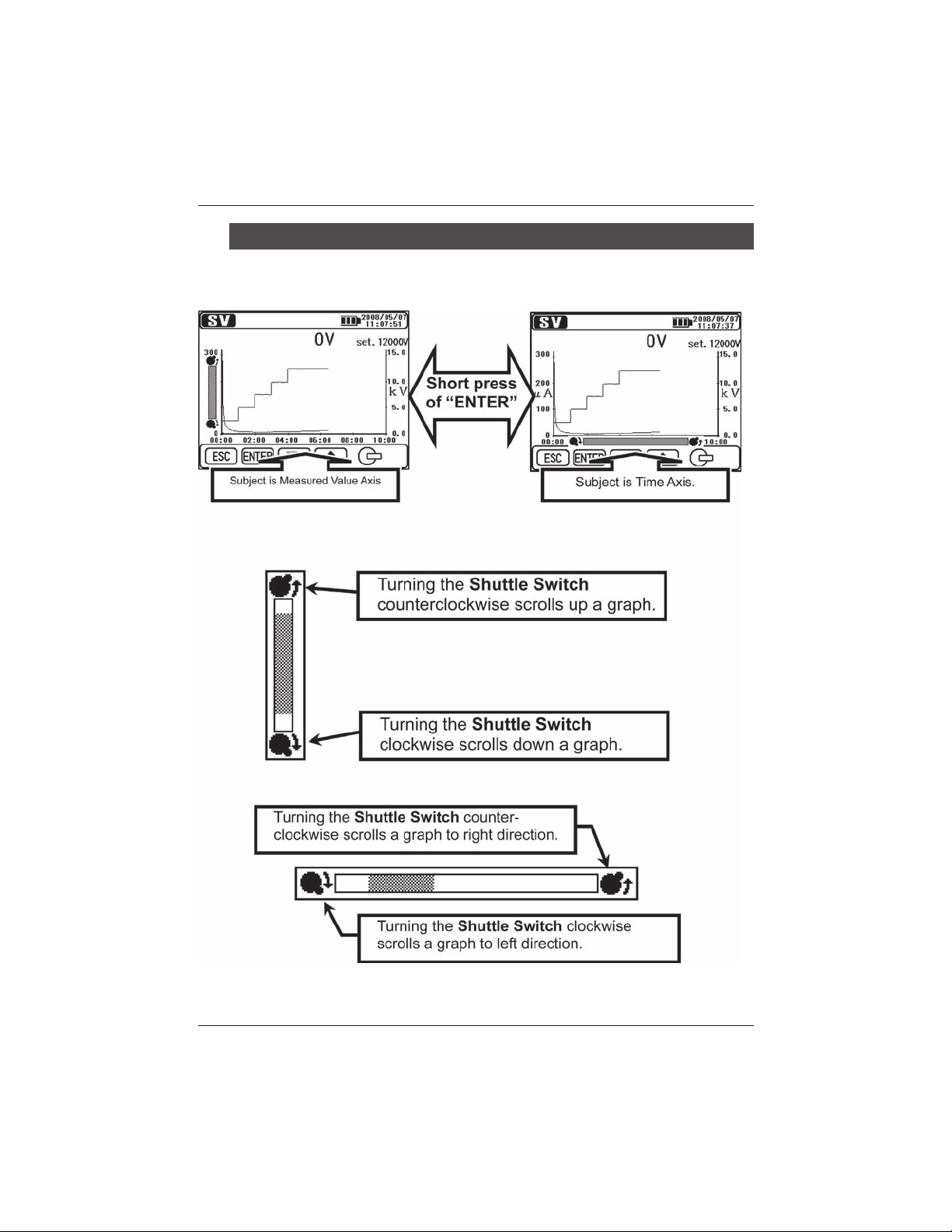
6. Measurement KEW3128
Switching the axis subject to zoom
A short press (within 1 sec) of the ENTER Key switches the Measured
Value Axis and the Time Axis to be zoomed.
● Scroll Bar at Measured Value Axis
● Scroll Bar at Time Axis
34 KEW3128
Find Quality Products Online at: sales@GlobalTestSupply.com
www.GlobalTestSupply.com
Page 35
KEW3128 6. Measurement
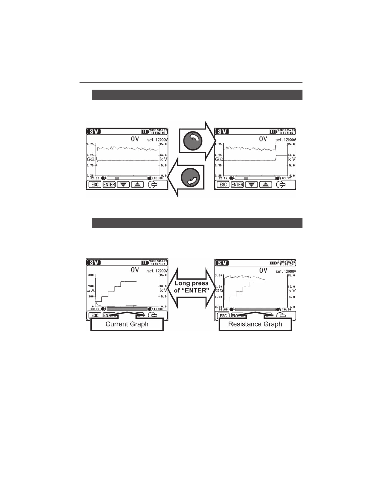
Scrolling of Graph
Turn the Shuttle Switch to scroll a graph. The Voltage Axis at SV
measurements is fixed and cannot be scrolled.
Switching the displayed graphs
A long press (1 sec or longer) of the ENTER Key switches Current and
Resistance graphs.
KEW3128 35
Find Quality Products Online at: sales@GlobalTestSupply.com
www.GlobalTestSupply.com
Page 36
6. Measurement KEW3128
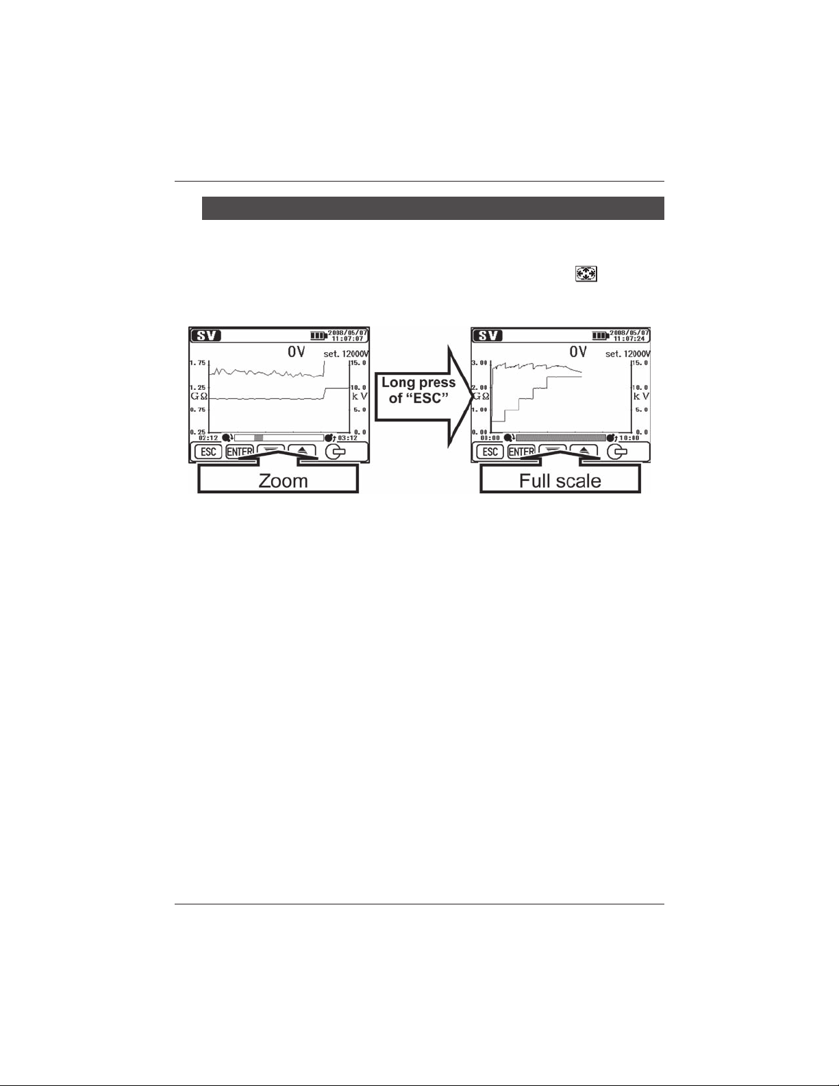
Displaying in Full-scale
A long press (1 sec or longer) of the ESC Key displays a graph in full-
scale. Displaying a graph in full-scale is also possible from the ENTER
Menu (=>P.37). Quit the Graph ZOOM Mode and select Full-scale
Display from the ENTER Menu.
36 KEW3128
Find Quality Products Online at: sales@GlobalTestSupply.com
www.GlobalTestSupply.com
Page 37
KEW3128 6. Measurement
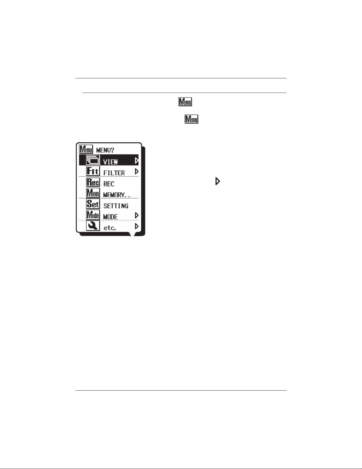
6.1.5 Menu
The Menu is available when is being displayed on the upper
middle of the LCD.
Pressing the ENTER Key while is being displayed on the LCD
pops up the Menu Window.
Move the cursor with the UP/DOWN Keys or
Shuttle Switch, and confirm the selection with
the ENTER Key. Pressing the ESC Key while the
Menu is being displayed closes the Menu Window.
Items displayed with
with submenus. Press the ENTER Key to access
to the submenus.
Pressing the ESC Key (within 1 sec) while the
submenus are being displayed returns to the
previous screen. A long press (1 sec or longer) of
the ESC Key closes the Menu Window.
mark are accompanied
KEW3128 37
Find Quality Products Online at: sales@GlobalTestSupply.com
www.GlobalTestSupply.com
Page 38
6. Measurement KEW3128
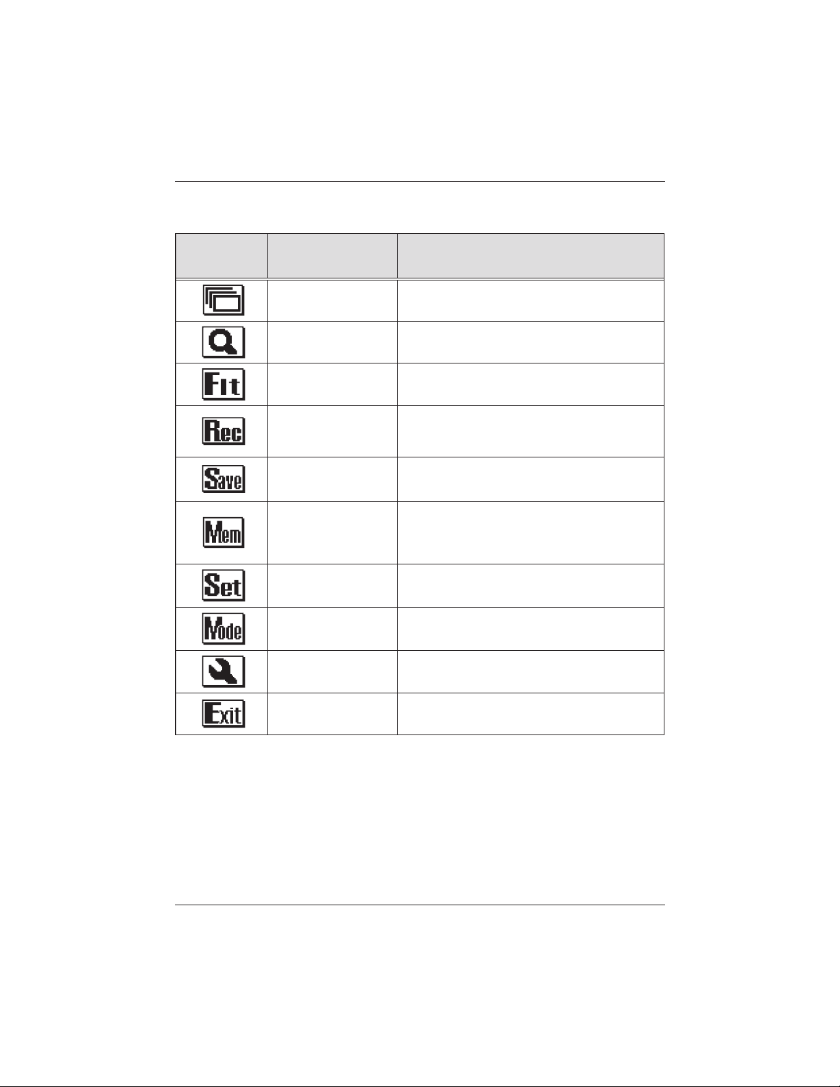
Followings are the details of each menu item.
Icon Name Function
View Change
Graph ZOOM
Filter
Record Records measured results continuously.
Save Saves the measured results only.
Internal Memory
Setting Moves to Measurement Setting Screen.
Mode Change Changes Measurement Modes.
Others
EXIT
Switches the screens.
(=>P.39 View Change)
Selects the Graph Zoom Mode.
(=>P.39 Graph ZOOM)
Makes setting for the Filter Mode.
(=>P.40 Filter)
Recalls or deletes the data in the internal
memory.
(=>P.42 Save Data)
Makes setting for clock.
(=>P.40 Other Functions)
Exits from Result Display Screen and
returns to Stand-by Mode.
38 KEW3128
Find Quality Products Online at: sales@GlobalTestSupply.com
www.GlobalTestSupply.com
Page 39

KEW3128 6. Measurement
View Change
Switches among Measured value, Current Graph and Resistance graph
views. Each sub-menu item has following function.
Icon Name Function
Measured value Displays Measured value View.
Current Graph Displays Current Graph View.
Resistance Graph Displays Resistance Graph View.
Graph ZOOM
Enters into the Graph Zoom Mode (=>P.33 Graph Operation), and
displays a graph in full-scale. Each sub-menu item has following function.
Icon Name Function
Time Axis ZOOM
Mea s u r ed va l u e
Axis ZOOM
Full-scale Display Displays a graph in full-scale.
KEW3128 39
Zooms a graph with reference to the Time
Axis (X-Axis).
Zoo ms a g raph wi th refe r ence to the
Measured Value Axis (Y-Axis).
Find Quality Products Online at: sales@GlobalTestSupply.com
www.GlobalTestSupply.com
Page 40
6. Measurement KEW3128
Filter
Switches on/off the Filter Function. (=>P.41 Filter Mode)
Each sub-menu item has following function.
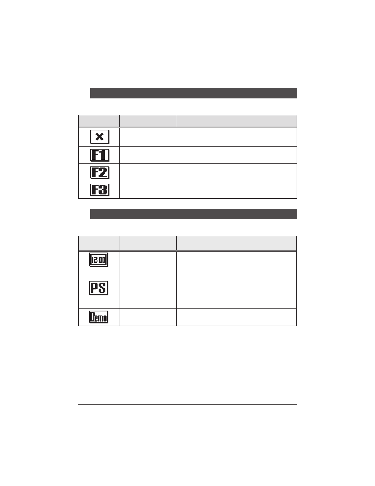
Icon Name Function
Filter OFF Displays the Measured Value View.
Filter 1 Enables Filter 1
Filter 2 Enables Filter 2
Filter 3 Enables Filter 3
Other Functions
Make settings for the instrument.
Each sub-menu item has following function.
Icon Name Function
Clock Setting
Print Screen
Demo Mode
40 KEW3128
Set the clock for KEW3128 instrument.
(=>P.47 Clock Setting)
Save the screen displayed on the LCD as
a BMP (bitmap) file. Act same as a long
press (1 sec or longer) of the Print screen
/Backlight Key.
(⇒P.17 Keys)
Switch to the Demo mode.
(⇒P.47 Demo mode)
Find Quality Products Online at: sales@GlobalTestSupply.com
www.GlobalTestSupply.com
Page 41

KEW3128 6. Measurement
6.1.6 Filter Mode
The KEW3128 has following 3 kinds of Filter Functions.
Filter Mode is effective to reduce the variations in readings due to external
influences during high resistance measurements.
Effectiveness of the Filter Mode becomes stronger when values get bigger. To
check sudden variations in resistances, the Filter Mode should be disabled.
Name Function
Filter OFF Disables the Filter (default setting)
Filter 1 Low-pass Filter (fc = 0.3Hz)
Filter 2 Moving Average (average of 5 data)
Filter 3 Low-pass Filter + Moving Average
Filter 1 : It uses it to cut the exchange element more than industrial frequency
(50/60Hz) when a high electric field has been generated around the
measurement thing.
Filter 2 : Four data immediately before the latest
measurements are averaged.
Filter 3 : Filter 1 and Filter 2 are used at the same time.
measurements a
nd the latest
KEW3128 41
Find Quality Products Online at: sales@GlobalTestSupply.com
www.GlobalTestSupply.com
Page 42

6. Measurement KEW3128
6.1.7 Save Data
Types of Save Data
The KEW3128 handles following 3 types of data.
● Logging Data (REC File)
Record the measured values (voltage, current and resistance values) at
every 1 sec from the beginning to the end of a measurement.
The max recording period is 90 min. The Measurement
Recoding should be selected on the ENTER Menu (=>P.37) while the
instrument is in the Stand-by mode to save the Logging data.
The time displayed at the top of the LCD indicating the time left that data
can be recorded. (=>P.65)
Data is saved as RECXX. (XX : 01~32)
Logging data (REC file) is recorded and saved in 15 seconds later from
the beginning of a measurement.
The data 15 seconds or earlier is shown as --. When viewing a graph
on the LCD of the instrument, the measured results for 15 seconds from
the beginning of a measurement are displayed with a straight line.
* It is same in real-time measurements using the supplied software KEW
Windows.
The measured value is saved in 15 seconds later from the beginning of a
measurement and the data 15 seconds or earlier is shown as --.
● Measured Data (SAVE File)
Measured data contains measured results only.
Select the Saving Measured Results on the ENTER Menu
(=>P.37) while the measured results are displayed on the LCD.
Data is saved as SAVEXX. (XX : 01~32)
● Print Screen (BMP File)
Captures and saves the screen images. A long press (1 sec or longer)
of the Print Screen/ Backlight Key saves screen images.
Data is saved as BMPXX. (XX : 01~32)
42 KEW3128
Find Quality Products Online at: sales@GlobalTestSupply.com
www.GlobalTestSupply.com
Page 43

KEW3128 6. Measurement
List of the Saved data
Select the Internal Memory on the ENTER Menu (=>P.37). Then a
list of saved data is displayed as follows.
Functions to recall (⇒displays the saved data), delete (⇒deletes the
saved data) and format the data (⇒formats the internal memory) are
available. Details of each parameter are as follows.
The latest data is displayed on the top.
KEW3128 43
Find Quality Products Online at: sales@GlobalTestSupply.com
www.GlobalTestSupply.com
Page 44

6. Measurement KEW3128
Recall the Saved Data
Display a list of the saved data.
Then use t h e U P / D O W N K e y or
Shuttle Switch and move the cursor
onto [LOAD], and press the ENTER
Ke y . The hi g h li ghte d c u r sor i s
displayed, and can be moved on the
files. Put the cursor on a desirable file
with the UP/ DOWN Key or Shuttle
Switch and press the ENTER Key.
A Confirmation Screen appears. Press
the ENTER Key to load the selected
data.
Pressing the ESC Key cancels to load
the data.
Displayed parameters are dependent on the selected files.
● Display the Logging data
The results of the saved data and the graphs of currents and resistances
can be displayed. The available operations against the displayed data
are same to that available when finishing measurements. Press the ESC
Key to return to the previous screen.
Items displayed at the top of the LCD are as follows.
44 KEW3128
Find Quality Products Online at: sales@GlobalTestSupply.com
www.GlobalTestSupply.com
Page 45

KEW3128 6. Measurement
● Display the Measured Data
Only the measured results can be viewed. The Graph Function isnt
available. The available operations against the displayed data are same
to that available when finishing measurements. Press the ESC Key to
return to the previous screen. Items displayed at the top of the LCD are
same to the display for the Logging data.
●Display the Print Screen
Display the saved BMP files. A black frame is displayed with flashing
around the LCD. Press the ESC Key to return to the previous screen.
Delete the saved data
Display a list of the saved data.
Then use the UP/DOWN Key or Shuttle
Sw itch and mov e th e cu rsor ont o
[DELETE], and press the ENTER Key.
The highlighted cursor is displayed,
and can be moved on the files. Put
the cursor on a file with the UP/DOWN
Key or Shuttle Switch and press the
ENTER Key to delete it.
A Confirmation Screen appears. Press
the ENTER Key to load the selected
data. Pressing the ESC Key cancels to
load the data.
KEW3128 45
Find Quality Products Online at: sales@GlobalTestSupply.com
www.GlobalTestSupply.com
Page 46

6. Measurement KEW3128
Format of the Internal Memory
Display a list of the saved data.
Then use the UP/DOWN Key or Shuttle
Sw i t ch an d m ov e t h e c u rso r o nt o
[FORMAT], and press the ENTER Key.
Then the memory is formatted and the List
Display Screen is displayed.Press the ESC
Key to cancel a format.
Max number of files that can be saved
The max number of files that can be saved is 32 files in total; addingup
all the Logging, Result and Print Screen data.
The save capacity is for 43000 data / for about 720 min in total (in case of
Logging data only). Max number of files that can be saved is dependent
on the file type.
File Type
10-min data 32 files
30-min data 23 files
Logging Data
60-min data 11 files
90-min data 7 files
Measured Data 32 files
Print Screen 32 files
46 KEW3128
Max number of files that can be saved
Find Quality Products Online at: sales@GlobalTestSupply.com
www.GlobalTestSupply.com
Page 47

KEW3128 6. Measurement
6.1.8 Clock Setting
Sel ect Clock Settin g o n t he
ENTER Menu (=>P.37). Adjust the time
in a following order: [year], [month], [day],
[h our], [ minut e] and [ displ ay for mat].
Pressing the ENTER Key confirms the
entry and proceeds to next step. Press the
ESC Key to return to the previous item.
Pressing the ENTER Key (1 sec or longer)
while [Finish] is highlighted makes the new
setting effective. A long press of the ESC
Key returns to the previous screen.
6.1.9 Demo Mode
KEW3128 has a Demo mode function to display simulated data as
measured results without generating output voltages.
Communication and save operations
work same as that work under normal
mode. The mark flashes at the top
of the LCD while the instrument is in
Demo mode.
D e m o m o d e is n t ca n c e l e d a f t e r
powering off the instrument.
Access from the ENTER menu (=> P.
37) to exit from the Demo mode.
KEW3128 47
Find Quality Products Online at: sales@GlobalTestSupply.com
www.GlobalTestSupply.com
Page 48

6. Measurement KEW3128
6. 2 Insulation Diagnosis Tests
This instrument can measure and perform following items as a part of
Insulation resistance Test.
- Insulation Resistance (IR)
- Polarization Index (PI)
- Dielectric Absorption Ratio (DAR)
- Dielectric Discharge (DD) *Auto-testing
- Step Voltage Test (SV)
Measurement Mode Function
Insulation
Resistance (IR)
Polarization Index(PI)
Dielectric Absorption
Ratio (DAR)
ielectric Discharge
D
(DD)
Step Voltage Test(SV)
Performs normal insulation resistance
measurements (consistent measurements)
Measures resistances twice and calculates
polarization index automatically.
(default value: 1 min, 10 min)
Measures resistances twice and calculates
dielectric absorption ratio automatically.
(default value: 15 sec, 1 min)
Calculates dielectric discharge based on the
measured capacitance of the measured object and
residual current values after testing.
Increases the set voltage by 20% every time
when pre-set time comes.
48 KEW3128
Find Quality Products Online at: sales@GlobalTestSupply.com
www.GlobalTestSupply.com
Page 49
KEW3128 6. Measurement
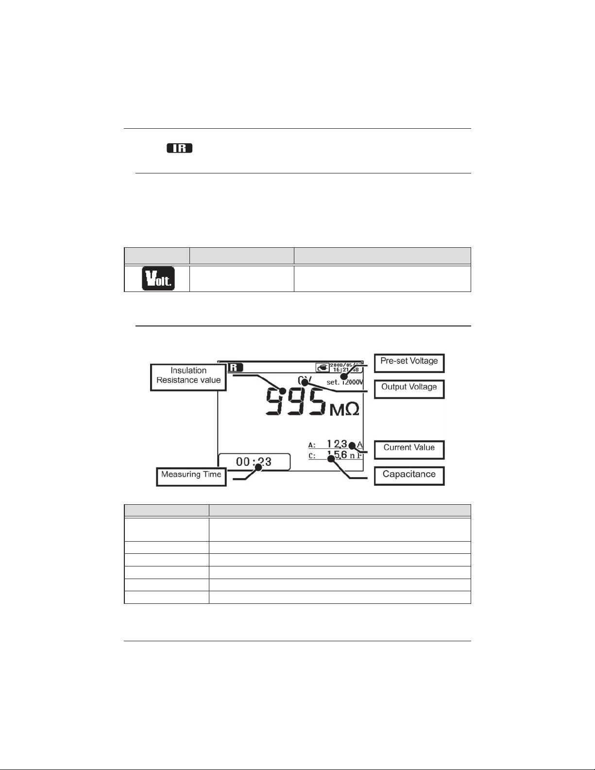
6. 3 IR Measurement
6.3.1 Setting Item
Setting items for IR measurements are as follows. Refer to Setting for
Measurement (=>P.30) and change the setting values.
At IR measurements, continuous measurements over 90 min are possible ,
however, the displayable area of the recorded data and graph are 90 min of
measured results. The later portions are displayed with numbers only.
Icon Name Details
Output voltage value Voltages to be output
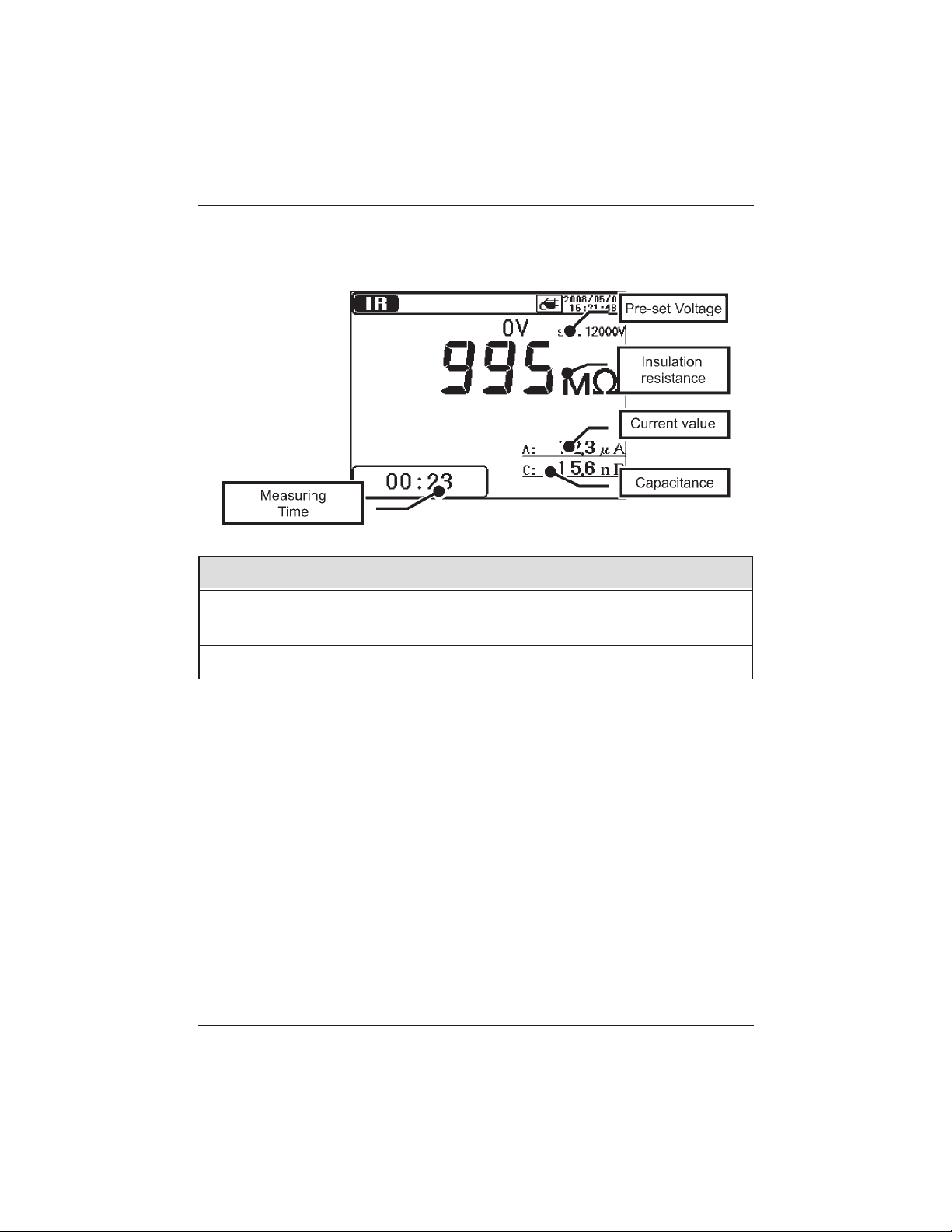
6.3.2 Measured Result
The result of IR measurement is displayed as follows.
Displayed Items Details
Insulation
Resistance
Measuring Time Elapsed time from a beginning of a measurement
Pre-set Voltage Pre-set output voltage value
Output Voltage Voltage being output
Current value Current value being measured
Capacitance Capacitance measured at discharge.
KEW3128 49
Find Quality Products Online at: sales@GlobalTestSupply.com
Measured insulation resistance value
www.GlobalTestSupply.com
Page 50
6. Measurement KEW3128
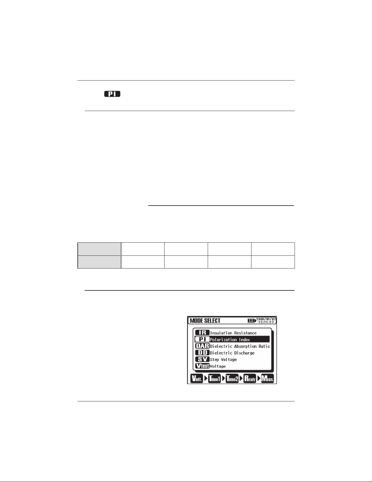
6. 4 PI Measurement (Polarization Index)
6.4.1 Polarization Index
PI : Polarization Index
This is a test to check a temporal increase of leakage currents flowing on
insulations. To determine a Polarization Index, first, measure insulation
resistance at 1 min intervals for 10 min. Then, divide the final value by
the initial reading and calculate a ratio. PI is dependent on the shape of
insulations a
is important to diagnosis the insulation of cables.
Polarization index =
nd influenced by moisture absorption, therefore, a check of PI
TIME 2
Insulation resistance value 3 or 10 min
after starting measurement
TIME 1
Insulation resistance value 30 sec or 1 min
after starting measurement
PI 4.0 or more
Criteria Best Good Warning Bad
4.0 ~ 2.0 2.0 ~ 1.0
1.0 or less
6.4.2 How to measure PI
1. Select the PI(Polarization Index) on the Mode Selection Screen.
Refer to Basic Operation (=>P.21) and operate the Screen.
50 KEW3128
Find Quality Products Online at: sales@GlobalTestSupply.com
www.GlobalTestSupply.com
Page 51
KEW3128 6. Measurement
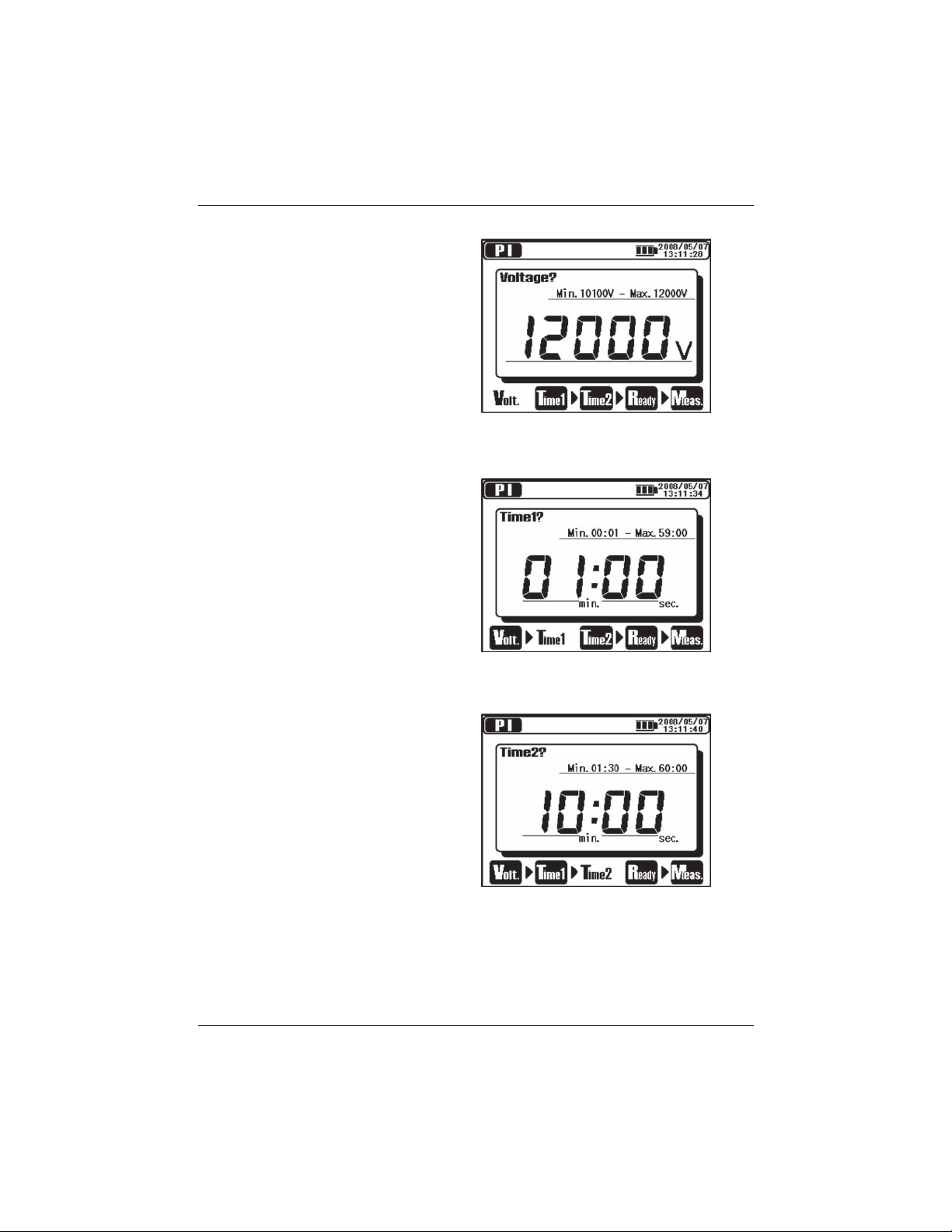
2. Set Voltage values.
3. Set TIME1.
4. Set TIME2.
KEW3128 51
Find Quality Products Online at: sales@GlobalTestSupply.com
www.GlobalTestSupply.com
Page 52
6. Measurement KEW3128
The instrument gets into the Stand-by Mode when settings are made.
Setting items for PI measurement are as follows. Refer to the Setting for
Measurement (=>P.30) and change settings.
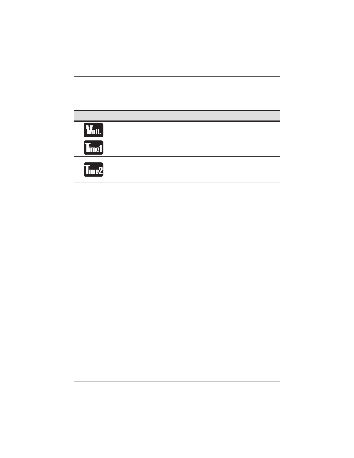
Icon Name Details
Output Voltage Voltage to be output.
PI Time 1
PI Time 2
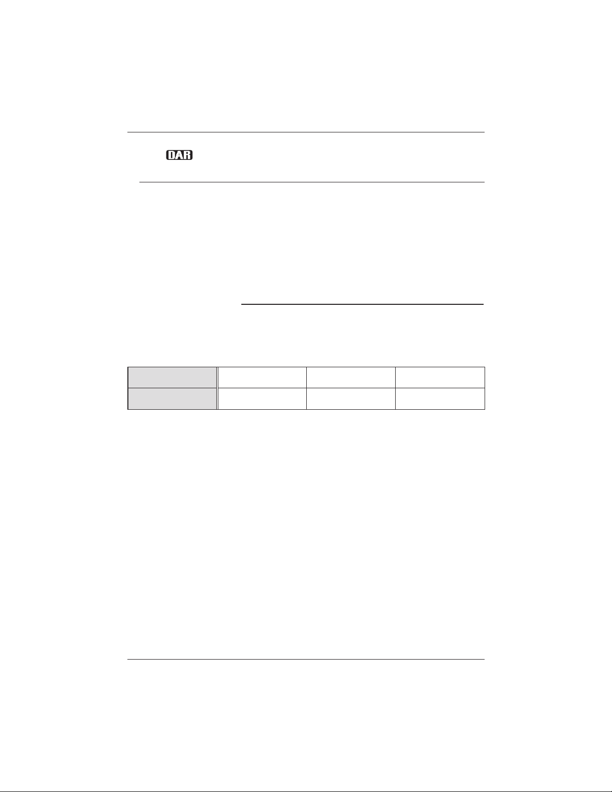
DAR Simultaneous display
DAR value is displayed during PI measurements and the measured results are
being displayed. TIME 1 and 2 values for DAR are the ones pre-set in the DAR
mode. Refer to 6.5.2 How to measure DAR (=>P.55) and set the time for DAR.
In case that DAR TIME 2 value is higher t
displayed on the LCD. A measurement stop when the PI TIME 2 comes. PI value
isnt displayed in the DAR measurement mode.
Measurement doesnt stop when PI Time
1 has been passed.
A measurement stops automatically when
this set time comes. This value should be
bigger than PI TIME 1.
han PI TIME 2 value, DAR value isnt
52 KEW3128
Find Quality Products Online at: sales@GlobalTestSupply.com
www.GlobalTestSupply.com
Page 53
KEW3128 6. Measurement
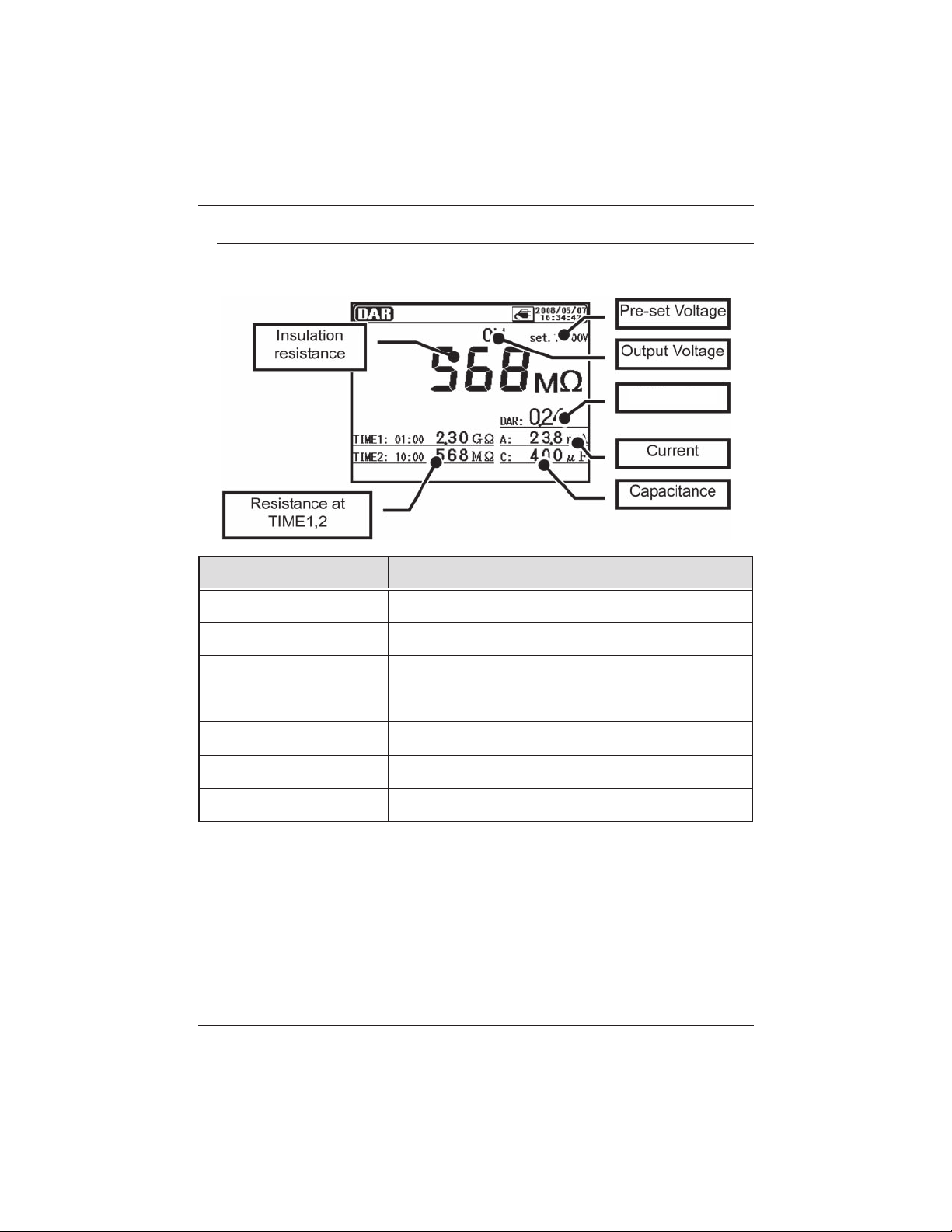
6.4.3 Measured Result
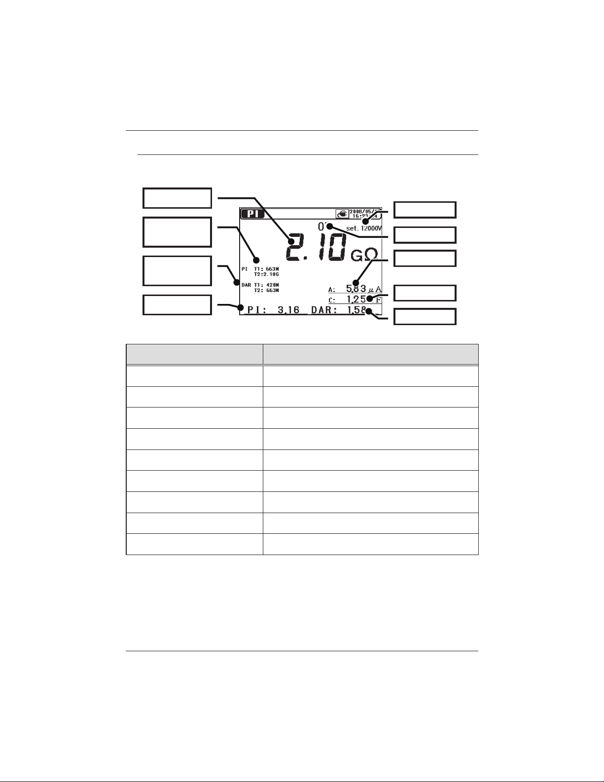
The result of PI measurement is displayed as follows.
Insulation
Pre-set Voltage
PI Resistance
at TIME1,2
DAR Resistance
at TIME1,2
PI value
Output
Current
Capacitanc
DAR value
Displayed Items Details
Insulation Resistance Measured insulation resistance value
PI Resistance at TIME1,2 PI Resistance value at TIME1 and TIME2
DAR Resistance at TIME1,2 DAR Resistance value at TIME1 and TIME2
PI Polarization Index value
Pre-set Voltage Pre-set output voltage value
Output Voltage Voltage being output
Current value Current value being measured
Capacitance Capacitance measured at discharge
DAR Die
KEW3128 53
Find Quality Products Online at: sales@GlobalTestSupply.com
www.GlobalTestSupply.com
lectric A
bsorption Ratio
Page 54
6. Measurement KEW3128
6. 5 DAR Measurement (Dielectric Absorption Ratio)
6.5.1 Dielectric Absorption Ratio
DAR : Dielectric Absorption Ratio
DAR measurement is almost same to PI measurement in a sense that
they test the time course of insulation. The only difference is that DAR
measurement can get result faster than the other.
TIME2
Dielectric
Absorption
Ratio
=
Insulation resistance value 30 sec or 1 min
after starting measurement
TIME1
Insulation resistance value 15 or 30 sec
after starting measurement
DAR 1.4 or more
Criteria Best Good Bad
1.25 ~ 1.0
1.0 or less
54 KEW3128
Find Quality Products Online at: sales@GlobalTestSupply.com
www.GlobalTestSupply.com
Page 55

KEW3128 6. Measurement
6.5.2 How to measure DAR
1.
2. Set Voltage values.
Select the DAR(Dielectric Absorption Ratio) on the Mode Selection
Screen. Refer to Basic Operation (=>P.21) and operate the Screen.
3. Set TIME1.
KEW3128 55
Find Quality Products Online at: sales@GlobalTestSupply.com
www.GlobalTestSupply.com
Page 56
6. Measurement KEW3128
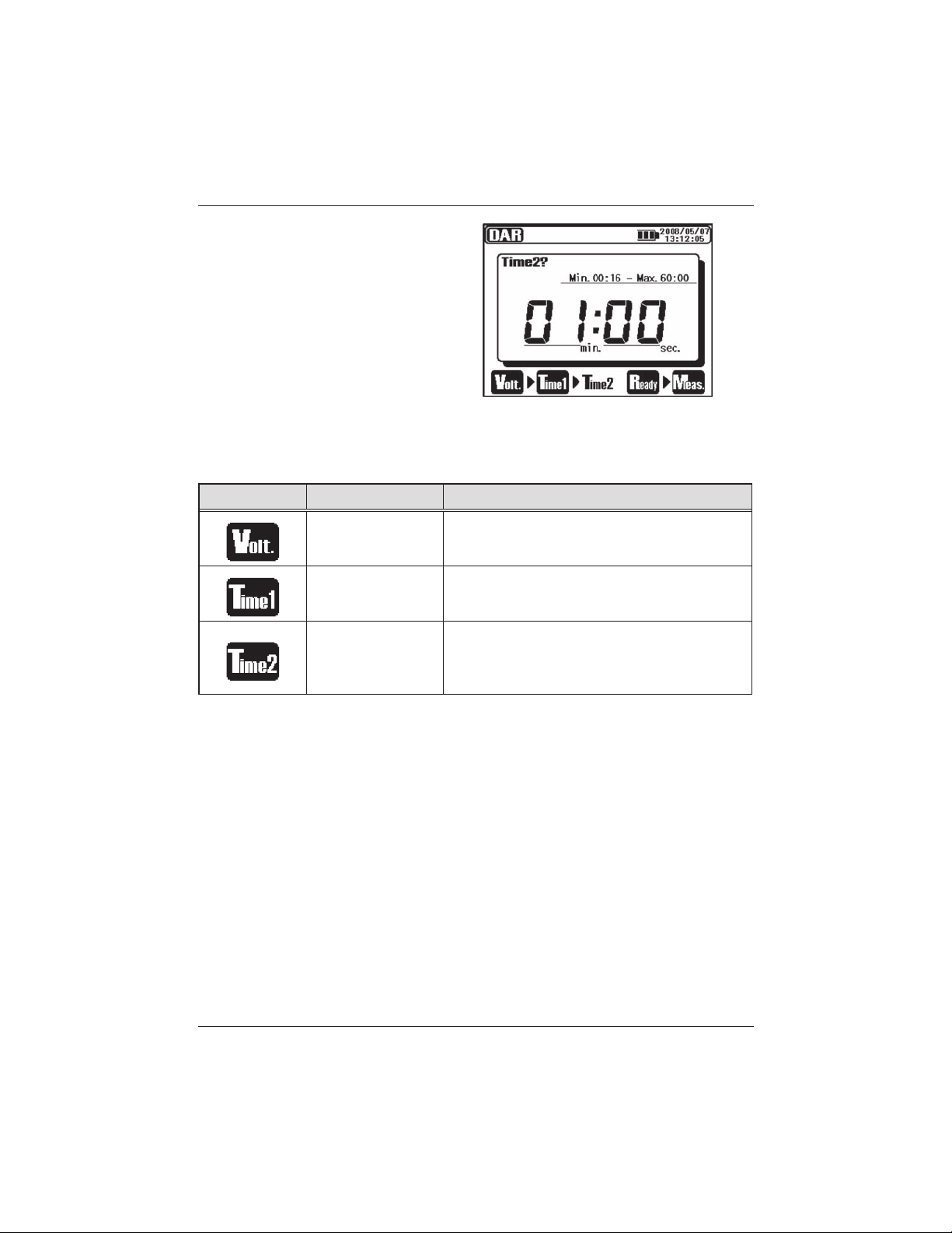
4. Set TIME2.
Setting items for DAR measurement are as follows. Refer to the Setting for
Measurement (=>P.30) and change settings.
Icon Name Details
Output Voltage Voltage to be output.
DAR Time 1
DAR Time 2
Measurement doesnt stop when
PI Time 1 has been passed.
A measurement stops automatically when
this set time comes.
This value should be bigger than PI TIME 1.
56 KEW3128
Find Quality Products Online at: sales@GlobalTestSupply.com
www.GlobalTestSupply.com
Page 57
KEW3128 6. Measurement
6.5.3 Measured Result
The result of DAR measurement is displayed as follows.
DAR value
Displayed Items Details
Insulation Resistance Measured insulation resistance value
Resistance at TIME1,2 Resistance value at TIME1 and TIME2
Pre-set Voltage Pre-set output voltage value
Output Voltage Voltage being output
DAR Dielectric Absorption Ratio
Current Current value being measured
Capacitance Capacitance measured at discharge.
KEW3128 57
Find Quality Products Online at: sales@GlobalTestSupply.com
www.GlobalTestSupply.com
Page 58

6. Measurement KEW3128
6. 6 DD Measurement (Dielectric Discharge)
6.6.1 Dielectric Discharge
DD : Dielectric Discharge
This measurement method is usually used to diagnosis multi-layer
insulations, which requires the instrument to measure the discharge current
and capacitance of the measured object 1 min after the removal of the
test voltage. This is a very good diagnostic insulation test that allows
deterioration and other problems voids in the multiple insulations to be
assessed.
Current value 1 min after
Dielectric
Discharge
=
completing measurement (mA)
Voltage value when a measurement
complete x Capacitance (F)
DD 2.0 or less
Criteria Good Warning Poor Very Poor
This criteria is a guide and could be slightly changed and be adapted to
particular objects under test based on practical experience of the users.
This method has been established to test high voltage generators installed
in electric power plants in the Europe countries.
58 KEW3128
2.0 ~ 4.0 4.0 ~ 7.0
7.0 or more
Find Quality Products Online at: sales@GlobalTestSupply.com
www.GlobalTestSupply.com
Page 59

KEW3128 6. Measurement
6.6.2 How to measure DD
1. Select the DD(Dielectric Discharge) on the Mode Selection
Screen. Refer to Basic Operation (=>P.21) and operate the Screen.
2. Set Voltage values.
3. Set TIME.
KEW3128 59
Find Quality Products Online at: sales@GlobalTestSupply.com
www.GlobalTestSupply.com
Page 60

6. Measurement KEW3128
Setting items for DD measurement are as follows. Refer to the Setting for
Measurement (=>P.30) and change settings.
Icon Name Details
Output Voltage Voltage to be output
Measuring Time
Measurements stop automatically and
DD values are calculated.
60 KEW3128
Find Quality Products Online at: sales@GlobalTestSupply.com
www.GlobalTestSupply.com
Page 61

KEW3128 6. Measurement
6.6.3 Measured Result
The result of DD measurement is displayed as follows.
DD value
Displayed Items Details
Insulation Resistance Measured insulation resistance value
Measuring Time Elapsed time from a beginning of a measurement
Pre-set Voltage Pre-set output voltage value
Output Voltage Voltage being output
DD Dielectric Discharge
Current Current value being measured
Capacitance Capacitance measured at discharge.
KEW3128 61
Find Quality Products Online at: sales@GlobalTestSupply.com
www.GlobalTestSupply.com
Page 62

6. Measurement KEW3128
6. 7 SV Measurement (Step Voltage)
6.7.1 Step Voltage
SV : Step Voltage
This is a test based on the principle that an ideal insulation will produce
identical readings at all voltages, while an insulation which is being over
stressed, will show lower insulation values at higher voltages. During the
test, the applied voltage incrementally steps by a certain voltage taking
successive 5-time measurement. Degradation of insulation may be doubt
when insulation resistances become lower at higher applied voltages.
6.7.2 Measurement Setting Items
1. Select the SV(Step Voltage) on the Mode Selection Screen. Refer
to Basic Operation (=>P.21) and operate the Screen.
2. Set Voltage values.
62 KEW3128
Find Quality Products Online at: sales@GlobalTestSupply.com
www.GlobalTestSupply.com
Page 63

KEW3128 6. Measurement
3. Set Step Time.
Setting items for SV measurement are as follows. Refer to the Setting for
Measurement (=>P.30) and change settings.
Icon Name Details
Output Voltage Voltage to be output
Step Time Time per step
In the SV measurement mode, measurements continue after the preset
Step time (V5) comes and automatically stop when 90 min pass.
KEW3128 63
Find Quality Products Online at: sales@GlobalTestSupply.com
www.GlobalTestSupply.com
Page 64

6. Measurement KEW3128
6.7.3 Measured Result
The result of SV measurement is displayed as follows.
Displayed Items Details
Insulation Resistance Measured insulation resistance value
Resistance at each
Step time
Pre-set Voltage Pre-set output voltage value
Output Voltage Voltage being output
Current Current value being measured
Capacitance Capacitance measured at discharge
Step time Pre-set Step time
64 KEW3128
Resistance value at each Step time (V1 – V5)
Find Quality Products Online at: sales@GlobalTestSupply.com
www.GlobalTestSupply.com
Page 65
KEW3128 6. Measurement
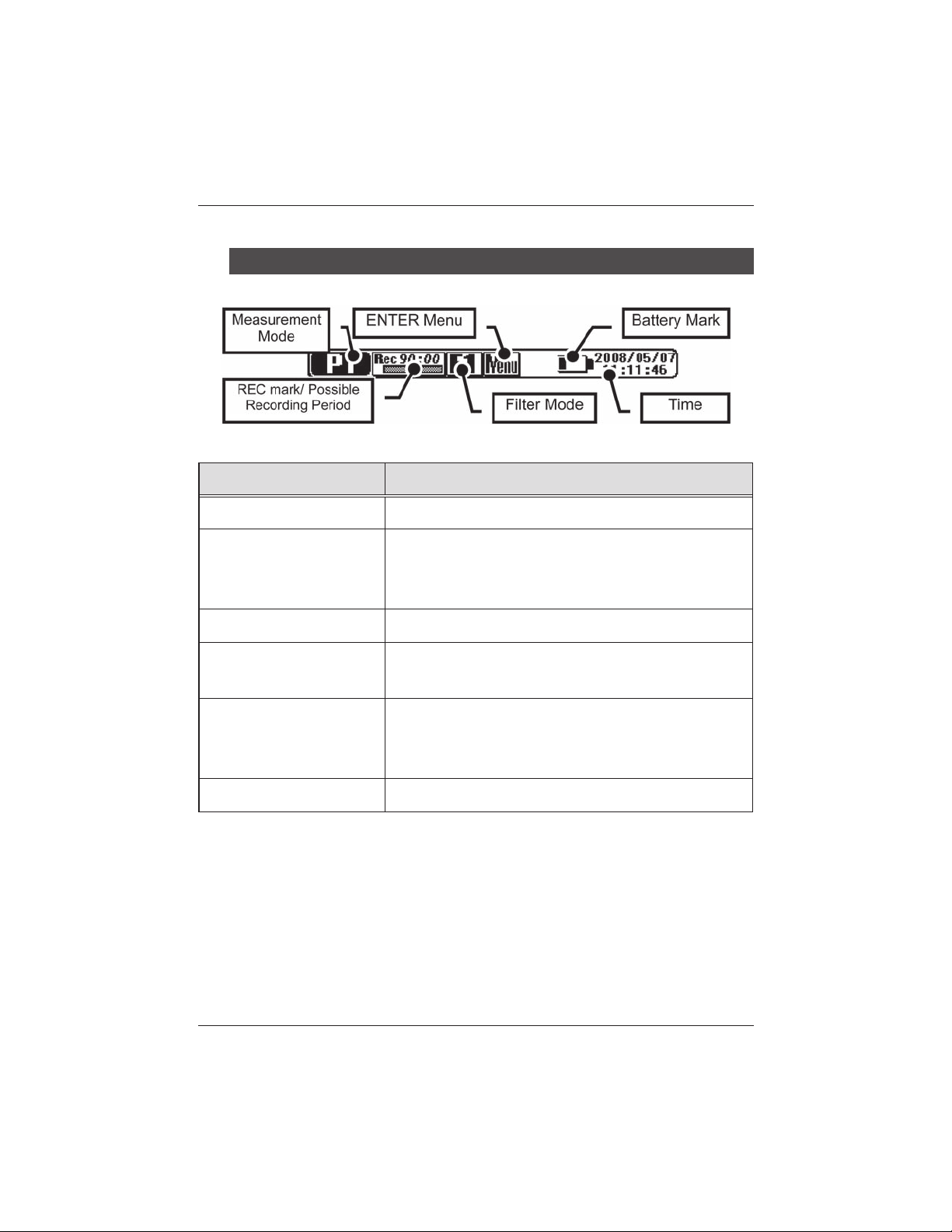
6. 8 Measurement Screen
Displayed items at the top of the LCD
Displayed Items Details
Measurement Mode Mark of the selected Measurement Mode
REC mark/ Possible
Recording Period
Filter Mode Mark of the selected Filter
ENTER Menu
Battery Mark
Time Present time and date
Displayed when REC is specified.
Possible recording time is displayed with a bar
graph and numbers.
Accessible to the ENTER Menu when pressing the
ENTER Key while this icon is being displayed.
Mark indicating the level of battery
mark is displayed when the instrument is operating
with an external power supply.
v
oltage.Different
KEW3128 65
Find Quality Products Online at: sales@GlobalTestSupply.com
www.GlobalTestSupply.com
Page 66

6. Measurement KEW3128
Items displayed at Result Display Screen
Following items are displayed on the LCD in stand-by mode and during a
measurement.
Displayed Items Details
Live Voltage Warning
Bar Graph
Measurement
Information
Measurement Time Elapsed time after a start of measurement
Pre-set Voltage Pre-set output voltage value
Output Voltage Voltage being output
I
nsulation Resistance Insulation resistance value being measured
Current Current value being measured
Pre-set Value Pre-set values for each Measurement Mode
66 KEW3128
Displayed while voltages are being output.Flashing
status shows discharge is in progress.
Ba r gra ph in dicatin g the meas ured i nsul ation
resistances
Supplementary info about each measurement
mode.
Find Quality Products Online at: sales@GlobalTestSupply.com
www.GlobalTestSupply.com
Page 67

KEW3128 6. Measurement
Items displayed at Graph Display Screen
Following items are displayed on the LCD with in stand-by mode and During
a measurement.
Displayed Items Details
Live Voltage Warning
Graph
Axis for Current/
Resistance values
Measuring Time Elapsed time after a start of measurement
Pre-set Voltage Pre-set output voltage
O
utput Voltage Voltage being output
Voltage Axis
(in SV Mode)
Pre-set Value Pre-set values for each measurement mode
KEW3128 67
Displayed while vo l t a g e s are being output.
Flashing status shows discharge is in progress.
Bar graph indicating the measured insulation
resistances.
Axis is switched between current and resistance
values depending on each graph.
value
Voltage Axis is displayed only in the SV
Measurement Mode.
Find Quality Products Online at: sales@GlobalTestSupply.com
www.GlobalTestSupply.com
Page 68
6. Measurement KEW3128
6. 9 Capacitance Measurement
6.9.1 Measurement Screen
Displayed Items Details
Capacitance value
Measuring Time Elapsed time after a start of measurement
At capacitance measurements, measured values are displayed when
insulation resistance measurements complete. When the output voltages
are 80% or less of the preset voltage values at an insulation resistance
measurement, readings for capacitance become
KEW3128 has a Protect Mode to limit charge currents in order to protect
the instrument when measuring 10uF or higher. In this mode, a message
Protect modeis displayed on the LCD.
The instrument exits from the Protect Mode automatically when a battery
charge completes or 5 min pass after entering into this mode.
68 KEW3128
Displays capacitance values of the measur ed
object after insulation resistance tests.
---.
Find Quality Products Online at: sales@GlobalTestSupply.com
www.GlobalTestSupply.com
Page 69
KEW3128 6. Measurement
6. 10 Voltage Measurement
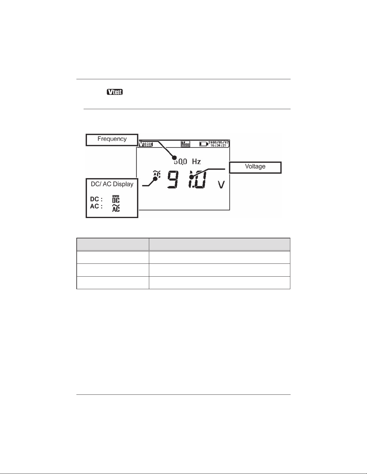
6.10.1 Measurement Screen
The result of Voltage measurement is displayed as follows.
Displayed Items Details
Frequency Frequency being measured
DC / AC Display DC / AC of measurement voltage
Voltage Voltage value being measured
KEW3128 69
Find Quality Products Online at: sales@GlobalTestSupply.com
www.GlobalTestSupply.com
Page 70
6. Measurement KEW3128
6. 11 Other Functions
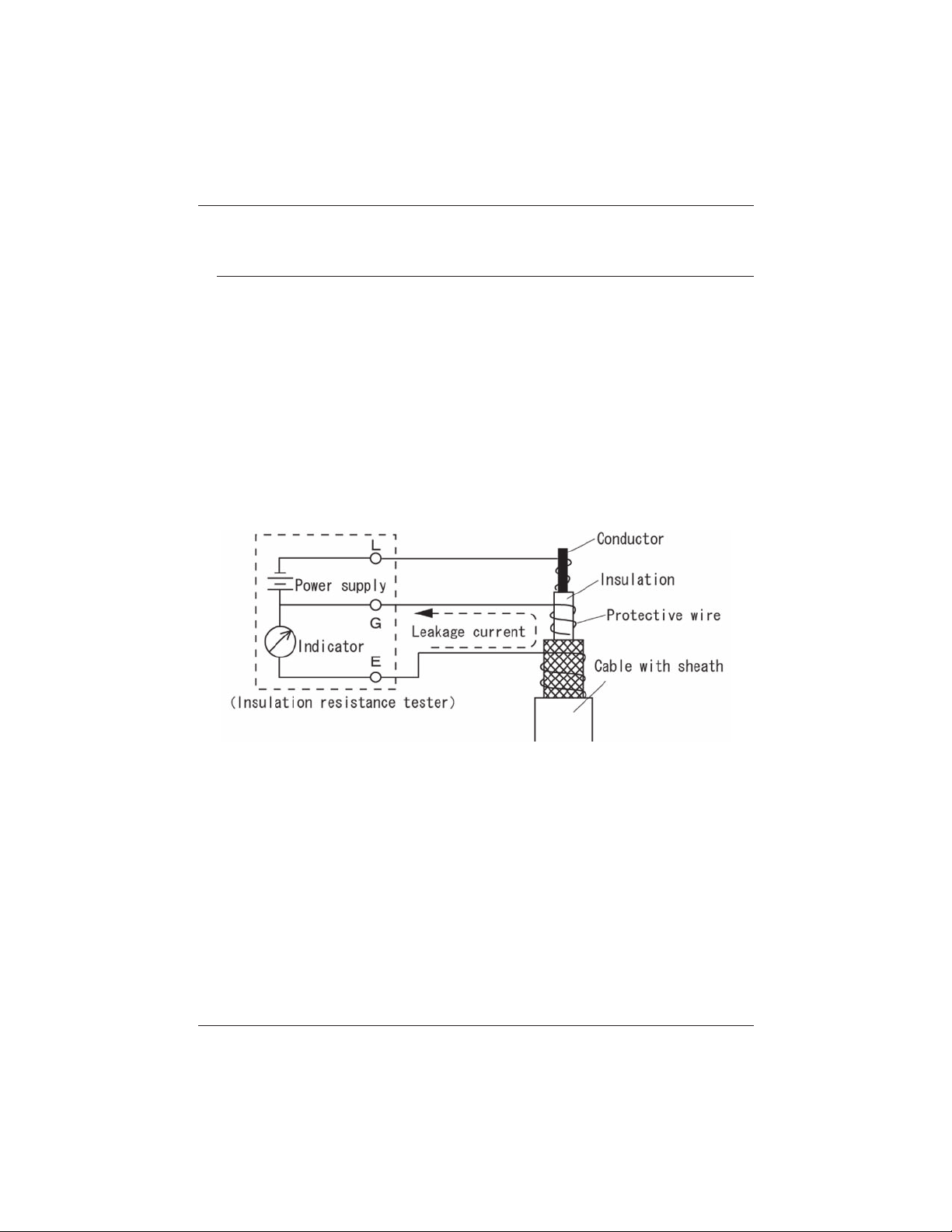
6.11.1 Use of Guard Terminal
When measuring insulation resistances of a cable, leakage currents flowing
on the surface of cable jacket and the currents flowing inside the insulator
are mixed and may cause error in readings. In order to prevent such error,
wind a conductive wire around the point where leakage currents flow.
Then connect it to the Guard terminal as shown in the below figure.
This is to move out the surface leakage resistance of the cable insulation
to measure only the volume resistance of insulator. Use the Guard cord
supplied with this instrument to connect the instrument and the Guard
terminal.
G Terminal Earthing Procedure
The G Terminal Earth System is a measurement method using a Guard
Terminal which is appropriate to measure the whole electrical paths
including high-voltage cable with the other high-voltage devices.Connect
the Guard Terminal to the Earth Electrode of the measured object and the
shielded wire of the cable to the Earth Terminal. In this case, disconnect the
shielded wire of the cable from the Earth Electrode.
To use this measurement method, the insulation resistance of sheath
(between the shielded wire and the ground) should be 1MΩ or more.
70 KEW3128
Find Quality Products Online at: sales@GlobalTestSupply.com
www.GlobalTestSupply.com
Page 71
KEW3128 6. Measurement
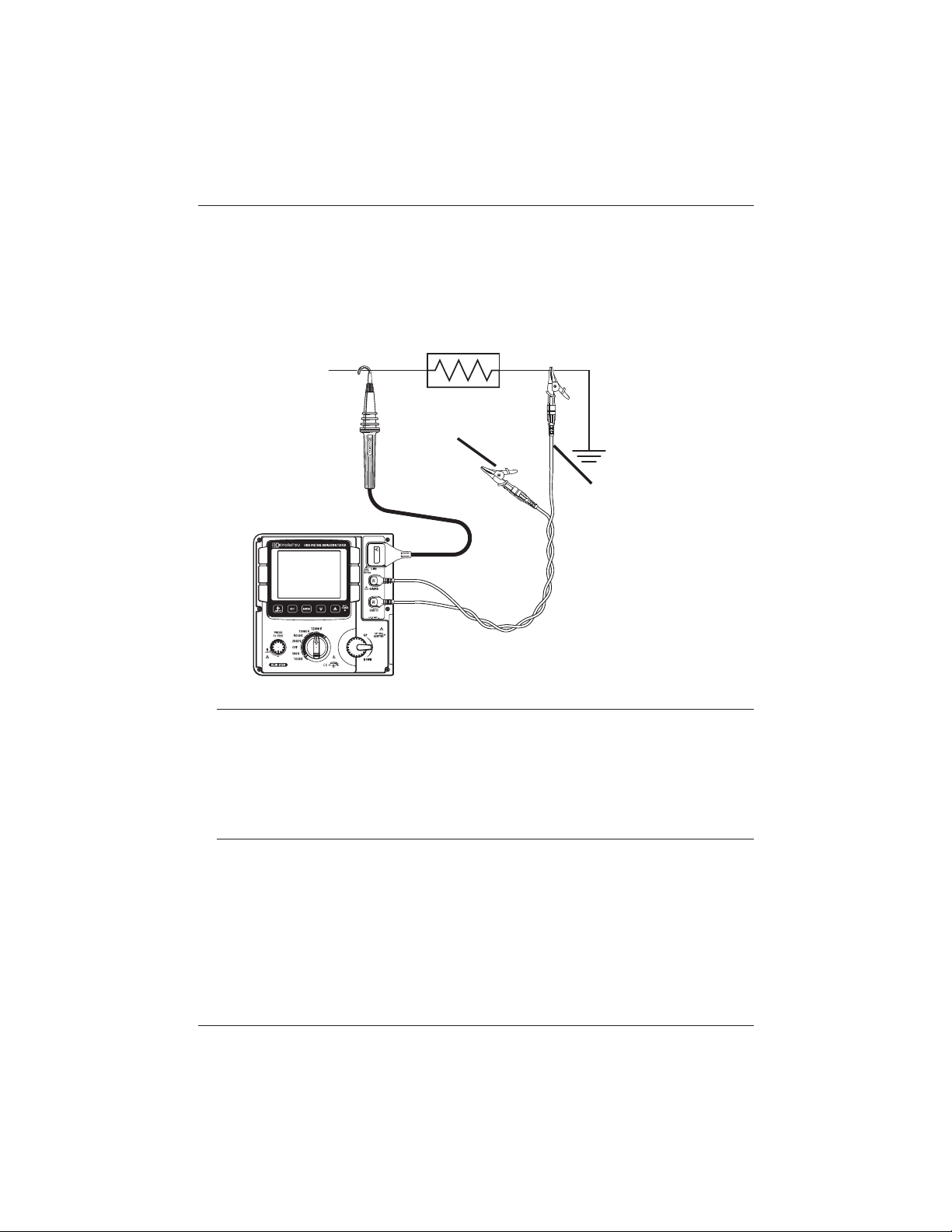
Use of Guard Terminal at high resistance measurements
It may take longer time to obtain accurate readings when measuring high
resistances of 100GΩ or higher while the instrument is operated with
battery instead of an external power supply.
In this case, wind the Guard Cord connected to the Guard Terminal to the
Earth Cord. Then accuracy of the readings gets better.
Guard Cord
Earth Cord
LINE
6.11.2 Backlight Function
This function to facilitate working at dimly illuminated location or at nighttime
work. Press the Backlight Button when the Range Switch is at any position
other than OFF. The Backlight will light up for about 1 min., and then
turned off automatically.
6.11.3 Auto-power-off Function
The instrument automatically turns off approx. 10 min after the last switch
operation. The instrument automatically turns off when approx 10 min pass
after a measurement with Timer function activated or 90 min of continuous
measurement in SV mode completes. To return to the normal mode, turn the
Range Switch to the OFF position, then to the desired position.
KEW3128 71
Find Quality Products Online at: sales@GlobalTestSupply.com
www.GlobalTestSupply.com
Page 72

7. Battery Charging and Replacement KEW3128
7. Battery Charging and Replacement
7. 1 How to charge battery
# DANGER
Use the special cord supplied with this instrument only. Firmly connect the
Power Cord to an outlet. Never connect it to a device on which electrical
potentials higher than AC240V exist.
Handling and storage instructions specified by the battery manufacturer
should be observed.
# WARNING
Connect the Power Cord to the instrument first. Cord to be firmly inserted.
Do not use the Cord if any abnormal conditions such as cracks or exposed
metal parts are present. When unplugging the Cord from the mains socket
outlet, do so by removing the Plug first and not by pulling the Cord.
① Set the Range Switch to the OFF position.
② Confirm a battery is installed in the instrument.
③ Connect the Power Cord to the instrument to feed power to the
instrument.
④ LED Status Indicator flashes in red and the Battery Mark also flashes
on the LCD.
⑤ The indicator lights up in green and the Battery Mark on the LCD stops
flashing and lights up. (Battery charge completes in about 8 hours.)
* Battery life and how many times can be charged are depended on conditions of
use and environment.
* Storing rechargeable lead-acid batteries in a low-charged state could lead to
reduced life and/or damage. When storing the battery for a long period, check
and charge the battery at regular intervals.
72 KEW3128
Find Quality Products Online at: sales@GlobalTestSupply.com
www.GlobalTestSupply.com
Page 73
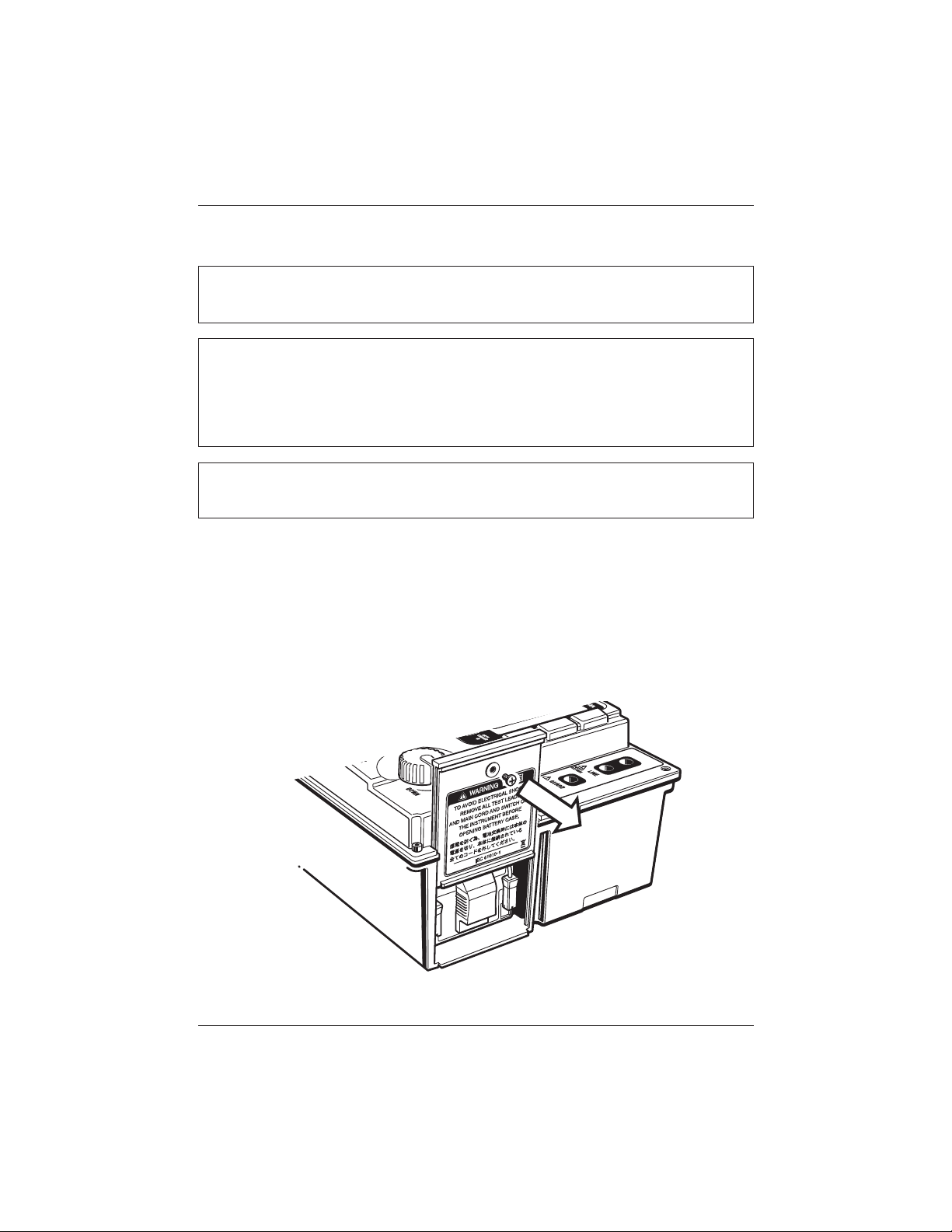
KEW3128 7. Battery Charging and Replacement
7. 2 How to Replace Battery
# DANGER
Never open the Battery Compartment Cover while making a measurement.
# WARNING
To avoid possible electric shock, remove test leads before opening the Battery
Compartment Cover. After replacing battery, be sure to tighten up the screw
for Battery Compartment Cover.
# CAUTION
Install a battery in correct polarity as marked inside.
① Remove the Power Cord from the instrument.
② Set the Range Switch to OFF position, and remove the Test Leads
from the instrument.
③ Remove the Battery Compartment Cover-fixing screws, and slide the
Cover upwards to remove it. (Attention should be paid not to lose
screws.)
KEW3128 73
Find Quality Products Online at: sales@GlobalTestSupply.com
www.GlobalTestSupply.com
Page 74

7. Battery Charging and Replacement KEW3128
④ Pull out the Tray toward, and take the battery out.
⑤ Pull up the Battery Connectors upward as indicated by arrow mark in
the below left illustration, and remove them.
+ (positive)
red
⑥ Remove the old battery and install a new one (rechargeable lead
storage battery PXL-12050: 12V 5Ah). Check the orientation of the
connectors (see above illustration on the right) and no deformation on
the metal terminals and install a battery in correct polarity. Then, insert
the Tray fully.
⑦ Install the Battery Compartment Cover so that the surfaces of the Cover
and the instrument become flat, and fix it with screws.
74 KEW3128
- (negative)
black
Find Quality Products Online at: sales@GlobalTestSupply.com
www.GlobalTestSupply.com
Page 75

KEW3128 8. Communication Function/ Supplied Software
8. Communication Function/ Supplied Software
● Interface
USB communication is possible by using this instrument with the supplied
USB Adapter (M-8212).
Communication method: USB Ver1.1
Followings can be done by USB communication:
* Downloading a file in the internal memory of the instrument to a PC
* Making settings for the instrument via PC.
* Displaying the measured results as a graph and saving them in real-
time.
● Software
KEW Windows for KEW3128 (Supplied CD-ROM )
● System Requirements
* OS (Operation System)
Windows2000/XP/VISTA(CPU: Pentium III 800MHz or higher)
* Memory
256Mbyte or more
* Display
Resolution 1024 × 768 dots, 65536 colors or more
* HDD (Hard-disk) space required
100Mbyte or more
* .NET Framework (2.0 or later)
● Trademarks
* Windows® and Microsoft® Excel are the registered trademark of
Microsoft in the United States.
* Pentium is a registered trademark of Intel in the United States.
KEW3128 75
Find Quality Products Online at: sales@GlobalTestSupply.com
www.GlobalTestSupply.com
Page 76

8. Communication Function/ Supplied Software KEW3128
8. 1 How to install the Software
Followings are the instructions to install the software KEW Windows and
KEW Windows for KEW3128.
① Before installing the software, followings shall be checked.
● To prepare your system to install this software, please close all open
programs.
● Be sure NOT to connect the instrument with USB until install is
completed.
● Installation shall be done with administrative right.
② Insert the CD-ROM in your PC's CD-ROM drive.
When the setup program doesn't run automatically, double click the
"KEWLauncher.exe".
Then following window appears. ClickNext.
76 KEW3128
Find Quality Products Online at: sales@GlobalTestSupply.com
www.GlobalTestSupply.com
Page 77

KEW3128 8. Communication Function/ Supplied Software
③ R ead t h rough and u n d erstand t h e L icense Ag reement, a n d
checkI accept….. Then click Next.
④ Enter the user information and specify the location to where install the
software. Then click Next.
KEW3128 77
Find Quality Products Online at: sales@GlobalTestSupply.com
www.GlobalTestSupply.com
Page 78

8. Communication Function/ Supplied Software KEW3128
⑤ Confirm the information on install, and click Install to start installing.
⑥ Click Finish when install completes.
78 KEW3128
Find Quality Products Online at: sales@GlobalTestSupply.com
www.GlobalTestSupply.com
Page 79

KEW3128 8. Communication Function/ Supplied Software
⑦ An installation of KEW Windows for KEW3128 is followed by the
installation of KEW Windows.
● To install the KEW Windows for KEW3128", you can follow the
same installation procedure described for KEW Windows .
If you need to remove this software, use the Add/Remove Programs tool in
the Control Panel.
KEW3128 79
Find Quality Products Online at: sales@GlobalTestSupply.com
www.GlobalTestSupply.com
Page 80
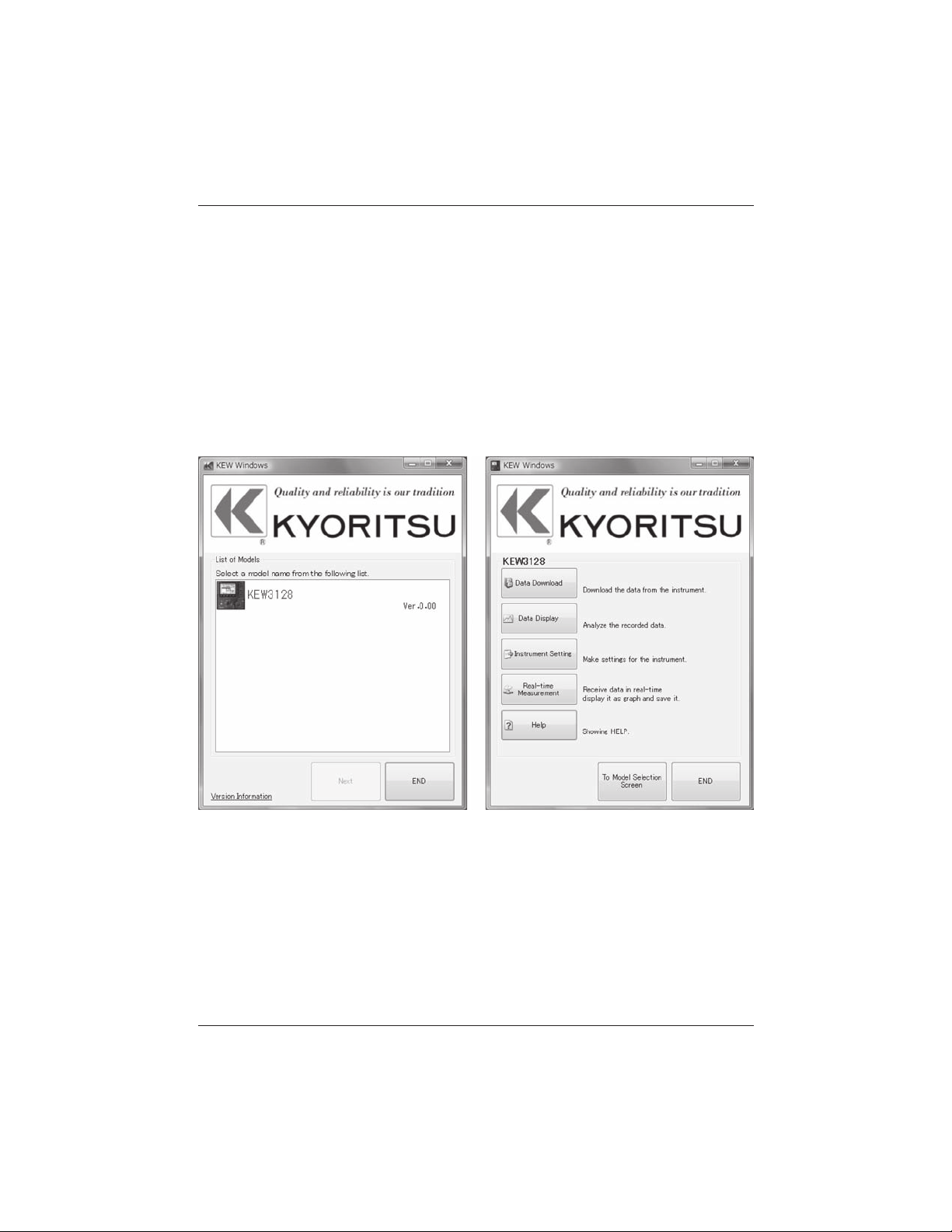
8. Communication Function/ Supplied Software KEW3128
8. 2 How to start KEW Windows for KEW3128
● Start and Quit
Start the software by; 1) clicking the icon for [KEW Windows] on the desktop,
or 2) clicking [Start] → [Program] → [KEW] → [KEW Windows]. Then the
KEW products, which have been installed in the KEW Windows, are
listed up. Select the KEW3128 on the list, and then click Next. Then
a main menu for KEW Windows for KEW3128 appears. Click [Data
Download] or [Instrument Setting].
80 KEW3128
Find Quality Products Online at: sales@GlobalTestSupply.com
www.GlobalTestSupply.com
Page 81

KEW3128 9. Accessories
9. Accessories
9. 1 Metal parts for Line Probe, and replacement
① Metal Parts
Standard, Hook Type: To be used to hook the instrument.
MODEL 8029: Tip metal, Straight Type(accessory)
② How to replace the metal parts
Turn the Line probe counterclockwise to remove the attached tip metal.
Put the tip metal you want to use to the hexagon socket and turn it to
clockwise together with the tip of probe, and tight up screws.
Standard Tip Metal
Hook Type
(Shipped out with being attached to the Line Probe)
Male Thread
Hexagon Socket
Tip Metal Straight Type
(accessory)
KEW3128 81
Find Quality Products Online at: sales@GlobalTestSupply.com
www.GlobalTestSupply.com
Page 82
10.Disposing the Product KEW3128
10. Disposing the Product
Waste Electrical and Electronic Equipment (WEEE), Directive 2002/96/EC
This Product complies with the WEEE Directive (2002/96/EC) marking
requirement. The affixed product label (see below) indicates that you must not
discard this electrical/electronic product in domestic household waste.
Product Category
With reference to the equipment types in the WEEE directive Annex 1, this
product is classified as a Monitoring and Control instrumentation product.
Disposing lead-storage batteries
When you throw away the batteries, be sure to cover their positive and negative
terminals and always observe local laws and regulations.
Insufficient insulation of the terminals may cause explosion or fire because
electrical energies remain in lead-storage batteries after use.
82 KEW3128
Find Quality Products Online at: sales@GlobalTestSupply.com
www.GlobalTestSupply.com
 Loading...