

Page 1
INSTRUCTION MANUAL
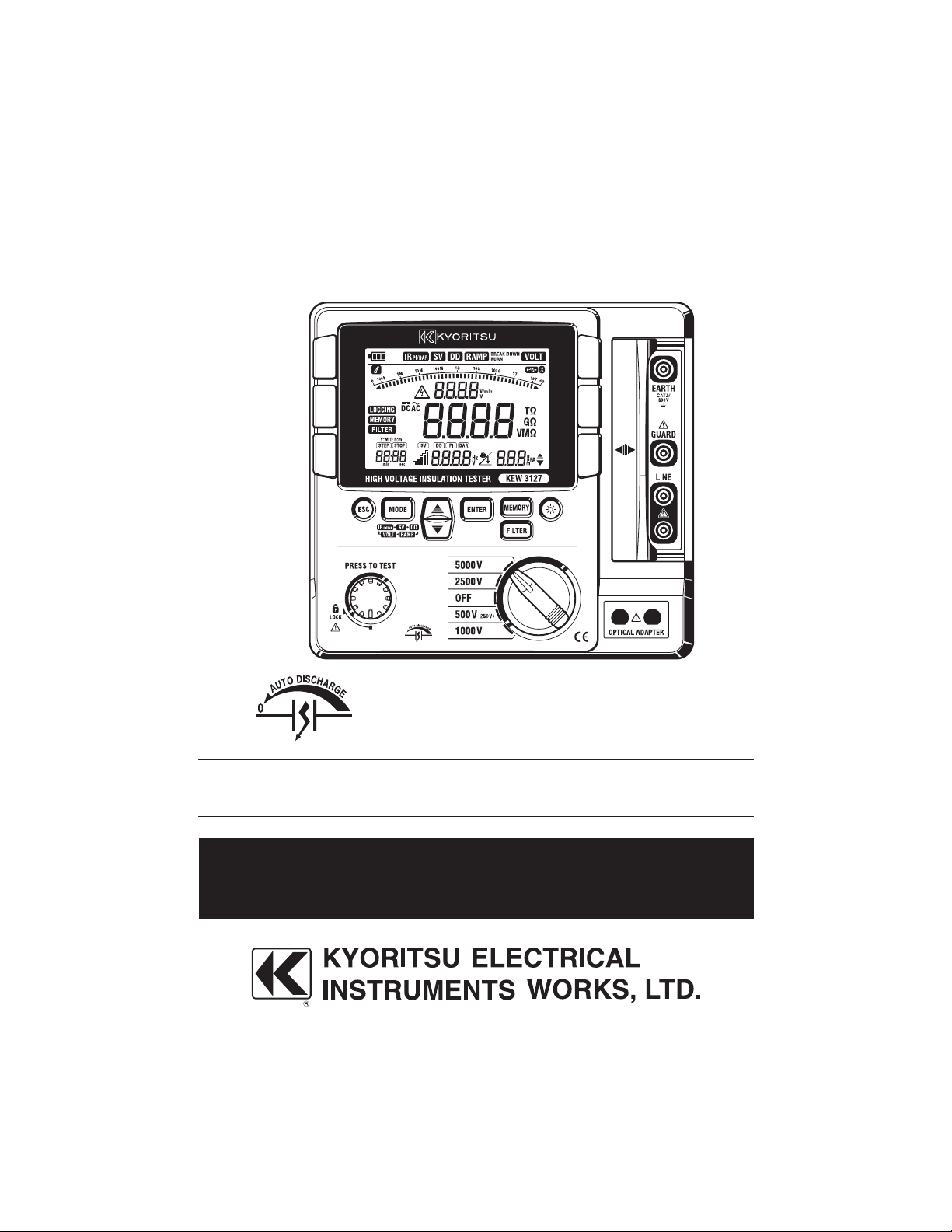
HIGH VOLTAGE INSULATION TESTER
KEW 3127
Find Quality Products Online at: sales@GlobalTestSupply.com
www.GlobalTestSupply.com
Page 2

Contents
1.Safety warnings ・・・・・・・・・・・・・・・・・・・・・・・・・・・・・・・・・・・・・・・・・・・・・・・・・・・1
2.Feature ・・・・・・・・・・・・・・・・・・・・・・・・・・・・・・・・・・・・・・・・・・・・・・・・・・・・・・・・・・5
3.Specification ・・・・・・・・・・・・・・・・・・・・・・・・・・・・・・・・・・・・・・・・・・・・・・・・・・・・・・ 6
4.Instrument layout ・・・・・・・・・・・・・・・・・・・・・・・・・・・・・・・・・・・・・・・・・・・・・・・・・10
4-1 Instrument layout ・・・・・・・・・・・・・・・・・・・・・・・・・・・・・・・・・・・・・・・・・・・・10
4-2 LCD display ・・・・・・・・・・・・・・・・・・・・・・・・・・・・・・・・・・・・・・・・・・・・・・・・・ 11
4-3 Opening and closing Hard case ・・・・・・・・・・・・・・・・・・・・・・・・・・・・・・・・12
4-4 Taking out KEW3127 from the Hard case ・・・・・・・・・・・・・・・・・・・・・・・12
5. Preparation for measurement ・・・・・・・・・・・・・・・・・・・・・・・・・・・・・・・・・・・・・・・13
5-1 Checking the battery voltage ・・・・・・・・・・・・・・・・・・・・・・・・・・・・・・・・・・13
5-2 Connecting test leads ・・・・・・・・・・・・・・・・・・・・・・・・・・・・・・・・・・・・・・・・13
6. Measurement ・・・・・・・・・・・・・・・・・・・・・・・・・・・・・・・・・・・・・・・・・・・・・・・・・・・・・14
6-1 Mains disconnection check (Voltage measurement) ・・・・・・・・・・・・・・14
6-2 Insulation resistance measurement ・・・・・・・・・・・・・・・・・・・・・・・・・・・・・15
6-3 About BREAKDOWN mode and BURN mode ・・・・・・・・・・・・・・・・・・・・19
6-4 Continuous measurement ・・・・・・・・・・・・・・・・・・・・・・・・・・・・・・・・・・・・・ 20
6-5 IRPI/DAR Measurement ・・・・・・・・・・・・・・・・・・・・・・・・・・・・・・・・・・・・・・・・・ 21
6-6 SV Measurement (Step Voltage) ・・・・・・・・・・・・・・・・・・・・・・・・・・・・・・・ 27
6-7 DD Measurement (Dielectric Discharge) ・・・・・・・・・・・・・・・・・・・・・・・・28
6-8 Ramp Measurement ・・・・・・・・・・・・・・・・・・・・・・・・・・・・・・・・・・・・・・・・・・30
6-9 Voltage characteristics of measuring terminal ・・・・・・・・・・・・・・・・・・・・ 32
6-10 Use of Guard terminal ・・・・・・・・・・・・・・・・・・・・・・・・・・・・・・・・・・・・・・・32
6-11 Filter function ・・・・・・・・・・・・・・・・・・・・・・・・・・・・・・・・・・・・・・・・・・・・・・・33
6-12 Backlight function ・・・・・・・・・・・・・・・・・・・・・・・・・・・・・・・・・・・・・・・・・・・ 33
6-13 Auto-power-off function ・・・・・・・・・・・・・・・・・・・・・・・・・・・・・・・・・・・・・・33
7. Memory function ・・・・・・・・・・・・・・・・・・・・・・・・・・・・・・・・・・・・・・・・・・・・・・・・・・34
7-1 Function details ・・・・・・・・・・・・・・・・・・・・・・・・・・・・・・・・・・・・・・・・・・・・・・34
7-2 How to save data ・・・・・・・・・・・・・・・・・・・・・・・・・・・・・・・・・・・・・・・・・・・・ 35
7-3 How to recall saved data ・・・・・・・・・・・・・・・・・・・・・・・・・・・・・・・・・・・・・・ 36
7-4 How to delete data ・・・・・・・・・・・・・・・・・・・・・・・・・・・・・・・・・・・・・・・・・・・37
Find Quality Products Online at: sales@GlobalTestSupply.com
www.GlobalTestSupply.com
Page 3

8.Clock Setting ・・・・・・・・・・・・・・・・・・・・・・・・・・・・・・・・・・・・・・・・・・・・・・・・・・・・38
9. Communication Function/ Software ・・・・・・・・・・・・・・・・・・・・・・・・・・・・・・・・・・39
9-1 KEW3127 Settings ・・・・・・・・・・・・・・・・・・・・・・・・・・・・・・・・・・・・・・・・・・・ 39
9-2 How to install the Software ・・・・・・・・・・・・・・・・・・・・・・・・・・・・・・・・・・・・42
9-3 How to start KEW Windows for KEW3127 ・・・・・・・・・・・・・・・・・・・45
9-4 Features of KEW Smart ・・・・・・・・・・・・・・・・・・・・・・・・・・・・・・・・・・・・・・・47
10.Battery Charging and Replacement ・・・・・・・・・・・・・・・・・・・・・・・・・・・・・・・48
10-1 How to charge battery ・・・・・・・・・・・・・・・・・・・・・・・・・・・・・・・・・・・・・・・48
10-2 How to replace battery ・・・・・・・・・・・・・・・・・・・・・・・・・・・・・・・・・・・・・・・49
11.Accessories ・・・・・・・・・・・・・・・・・・・・・・・・・・・・・・・・・・・・・・・・・・・・・・・・・・・・51
11-1 Metal part for Line Probe, and replacement ・・・・・・・・・・・・・・・・・・・・・51
11-2 How to use the adaptor for recorder ・・・・・・・・・・・・・・・・・・・・・・・・・・・52
11-3 Line probe with alligator clip ・・・・・・・・・・・・・・・・・・・・・・・・・・・・・・・・・・52
12. Disposing the Product ・・・・・・・・・・・・・・・・・・・・・・・・・・・・・・・・・・・・・・・・・・・・53
Find Quality Products Online at: sales@GlobalTestSupply.com
www.GlobalTestSupply.com
Page 4

1. Safety warnings
This instrument has been designed, manufactured and tested according to IEC
61010: Safety requirements for Electronic measuring apparatus, and delivered in
the best condition after passed the inspection. This instruction manual contains
warnings and safety rules which must be observed by the user to ensure safe
operation of the instrument and retain it in safe condition.
Therefore, read through these operating instructions before using the instrument.
# WARNING
● Read through and understand instructions contained in this manual before
starting to use the instrument.
● Save and keep the manual at hand to enable quick reference whenever
necessary.
● The instrument is to be used only in its intended applications.
● Understand and follow all safety instructions contained in the manual.
It is essential that the above instructions are adhered to. Failure to follow the
above instructions may cause injury, instrument damage and/or damage to
equipment under test.
The symbol
related parts in the manual for safe operation of the instrument. It is essential to
read the instructions wherever the # symbol appears in the manual.
# indicated on the instrument means that the user must refer to
# DANGER is reserved for conditions and actions that are likely to cause
serious or fatal injury.
# WARNING is reserved for conditions and actions that can cause serious
or fatal injury.
# CAUTION is reserved for conditions and actions that can cause injury or
instrument damage.
- 1 -
Find Quality Products Online at: sales@GlobalTestSupply.com
www.GlobalTestSupply.com
Page 5

# DANGER
● Never make measurement on the circuit in which electrical potential to
ground over 600V exists.
● Do not attempt to make measurement in the presence of flammable gasses.
Otherwise, the use of the instrument may cause sparking, which can lead to
an explosion.
● Never attempt to use the instrument if its surface or your hand is wet.
● Be careful not to short-circuit the power line with the metal part of the test
leads when measuring voltage. It may cause personal injury.
● Do not apply inputs exceeding the maximum allowable measuring range.
● Do not press the Test button with test leads connected to the instrument.
● Never open the battery compartment cover while making a measurement.
● Do not touch the circuit under test while measuring insulation resistance or
right after a measurement. You may get an electric shock by a test voltage.
# WARNING
● Never attempt to make any measurement if any abnormal conditions are
noted, such as broken case and exposed metal parts or when inner jackets
are seen through the nicked outer jacket.
● Do not rotate the Range switch with the test leads connected to the equipment
under test.
● Do not install substitute parts or make any modification to the instrument.
Return the instrument to your local Kyoritsu distributor for repair or recalibration.
● Do not try to replace the battery if the surface of the instrument is wet.
● Firmly insert the plug into the terminal when using test leads.
● Ensure that the instrument is powered off when opening the battery
compartment cover for battery replacement.
- 2 -
Find Quality Products Online at: sales@GlobalTestSupply.com
www.GlobalTestSupply.com
Page 6
# CAUTION
● Always make sure to set the Range switch to the appropriate position before
making a measurement.
● Set the Range Switch to OFF position after use and disconnect the
test leads from the instrument. Remove the battery if the instrument is to be
stored and will not be used for a long period.
● Do not expose the instrument to the direct sun, high temperature and
humidity or dewfall.
● Use a cloth dipped in alcohol for cleaning the test leads and the part around
the measuring terminals.
● Do not store the instrument if it is wet.
● The Voltage warning mark is being displayed during a measurement and it
flashes when voltages 30V(DC/AC) or more exist on the circuit under test.
Symbols
Danger of possible electric shock
Instrument with double or reinforced insulation
DC
AC
Earth terminal
Crossed-out wheel bin symbol (according to WEEE Directive: 2002/96/
EC) indicating that this electrical product may not be treated as
household waste, but that it must be collected and treated separately.
- 3 -
Find Quality Products Online at: sales@GlobalTestSupply.com
www.GlobalTestSupply.com
Page 7
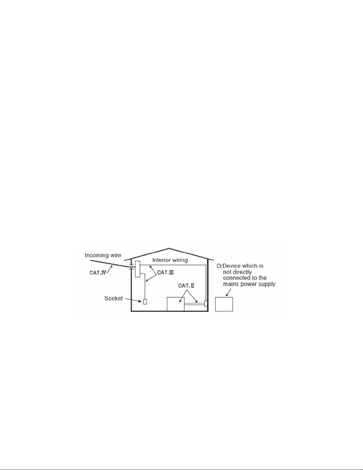
○ Measurement categories(Over-voltage categories)
To ensure safe operation of measuring instruments, IEC 61010 establishes safety
standards for various electrical environments, categorized as O to CAT.IV, and
called measurement categories. Higher-numbered categories correspond to
electrical environments with greater momentary energy, so a measuring instrument
designed for CAT.III environments can endure greater momentary energy than
one designed for CAT.II.
O : Circuits which are not directly connected to the mains power supply.
CAT.II : Electrical circuits of equipment connected to an AC electrical outlet by
a power cord.
CAT.III : Primary electrical circuits of the equipment connected directly to the
distribution panel, and feeders from the distribution panel to outlets.
CAT.IV : The circuit from the service drop to the service entrance, and to the
power meter and primary overcurrent protection device (distribution
panel).
- 4 -
Find Quality Products Online at: sales@GlobalTestSupply.com
www.GlobalTestSupply.com
Page 8

2. Feature
KEW3127 is a microcomputer controlled, high voltage insulation resistance tester
with 5-range for measuring insulation resistance.
● Designed to following safety standards:
IEC 61010-1 (CAT. IV 600V Pollution degree 2)
IEC 61010-031 (Requirements for hand-held probes)
● With auto-discharge function
When insulation resistance like a capacitive load is measured, electrical charges
stored in capacitive circuits are automatically discharged after measuring.
Discharge can be checked on the voltage monitor.
● Backlight function to facilitate working at dimly illuminated location or at
nighttime work.
● Bar graph to display measured result
● LIVE circuit warning symbols plus audible warning
● With Auto-power off function
To prevent the instrument being left powered on and conserve battery power,
the instrument automatically turns off approx. 10 min. after the last switch
operation.
● Auto-measurement and display of PI (Polarization Index), DAR (Dielectric
Absorption Ratio) and DD (Dielectric discharge), Step Voltage (SV), leakage
current and capacitance measurements, and Ramp measurement for
breakdown voltage check.
● Filter function to reduce the variations in readings due to external influences
● With a short current of max 5mA, quick measurement is possible even if the
object under test has capacitive components.
● Internal saved data and real-time measuring data can be transferred to a PC
via Bluetooth communication or by using special USB adapter (MODEL8212
USB). Easy settings for KEW3127 and data analysis via PC are possible with
the application software.
- 5 -
Find Quality Products Online at: sales@GlobalTestSupply.com
www.GlobalTestSupply.com
Page 9

3. Specification
● Applicable standards
IEC 61010-1 Measurement CAT. IV 600V Pollution degree2
IEC 61010-031 Standard for hand-held probes
MODEL7165A(CAT. IV 600V)
MODEL7224A(CAT.IV 600V)
MODEL7225A(CAT.IV 600V)
* When KEW3127 and the test lead are combined and
used together, whichever is lower category either of
them belong to is applied.
IEC 61326-2-2 EMC standard
IEC 60529 IP40(Instrument)
IP65 (Hard case)
● Measuring range and accuracy (Temperature, humidity: 23±5Cº, 45 - 75%RH)
<Insulation resistance tester>
Rated
voltage
Measuring
range(*2)
Display range
Open circuit
voltage
Rated
current
Short-circuit
current
250V(*1) 500V 1000V 2500V 5000V Accuracy
0.0-99.9MΩ
100-999MΩ
1.00-9.99GΩ
0.0M - 12.00GΩ 0.0M-120.0GΩ 0.0M-240GΩ 0.0M-1200GΩ 0.0M-12.00TΩ
DC 250V
+10%, -10%
0.0-99.9MΩ
100-999MΩ
1.00-9.99GΩ
10.0-99.9GΩ
DC 500V
+20%, -10%
For 10 sec after a test is started : max 5mA,
after that : 1.4mA
0.0-99.9MΩ
100-999MΩ
1.00-1.99GΩ
2.00-9.99GΩ
10.0-99.9GΩ
100-199GΩ
DC 1000V
+20%, -0%
1mA or more,
1.2mA or less
(at 1MΩ load)
0.0-99.9MΩ
100-999MΩ
1.00-9.99GΩ
10.0-99.9GΩ
100-999GΩ
DC 2500V
+20%, -0%
1mA or more,
1.2mA or less
(at 2.5MΩ load)
0.0-99.9MΩ
100-999MΩ
1.00-9.99GΩ
10.0-99.9GΩ
100-999GΩ
1.00-9.99TΩ
DC 5000V
+20%, -0%
1mA or more,
1.2mA or less
(at 5MΩ load)
±5%rdg
±3dgt
±20%rdg
(*1) 250V Range is for IRPI/DAR measurement only.
(*2) Measuring range goes to one lower range when the applied input drops to
80% or lower of the rating of the lower range. Measurement accuracy to be
applied is changed when the range goes to the lower range.
- 6 -
Find Quality Products Online at: sales@GlobalTestSupply.com
www.GlobalTestSupply.com
Page 10

<Voltage monitor for insulation resistance range>
Rated voltage 250V 500V 1000V 2500V 5000V Accuracy
Measuring
range
This monitor is used to check whether electrical charge stored on the equipment
under test is discharged or not. The measured voltage value displayed on the
LCD is a reference value.
Please be noted that the indicated value, when external AC voltage is applied to
the instrument, is not the correct value.
<Volt meter >
Volt
Frequency 45.0-65.0Hz(*1) 0.1Hz ±0.2Hz
(*1)When the measured voltage is less than 30V or DCV is measured, the
frequency is displayed as ----Hz on the LCD.
<Ammeter (Output Current)>
Measuring range Accuracy
0.00nA~5.50mA
(*1) If result of resistance measurement is 10MΩ or more, output current is
determined by resistance and voltage.(Accuracy is derived from measured
resistance specification and measured voltage specification)
<Capacity meter>
Rated voltage Measuring range Accuracy
250V 〜 2500V range 5.0nF 〜 50.0μF
5000V range 5.0nF 〜 25.0μF
【Calculated Value】
PI,DAR,DD
Measurement Mode Display range Computational error
30-330V 30-650V 30-1200V 30-3000V 30-6000V ±10%rdg±20V
(resolution 10V)
Measuring range Resolution Accuracy
DC voltage:±30 - ±600V
AC voltage: 30 - 600V
(50/60Hz)
1V ±2%rdg±3dgt
±10%rdg(*1)
±5%rdg±5dgt
PI 0.00 〜 9.99 ±2dgt
DAR 0.00 〜 9.99 ±2dgt
DD 0.00 〜 9.99 ±2dgt
- 7 -
Find Quality Products Online at: sales@GlobalTestSupply.com
www.GlobalTestSupply.com
Page 11

●Display: Liquid crystal display
Bar graph: Max. 41points
DAR/PI value: 9.99
Time: 99:59
●Low battery warning: Battery mark display (in 4 levels)
●Overrange indication: OL mark appears at insulation resistance
range and Hi mark at voltage range.
●Auto-ranging: Range shifts to upper range : 1000 counts
Range shifts to lower range : 80 counts
(Only at the insulation resistance range)
●Auto-power-off: Power off function operates in 10 min. after
the last switch operation.
●Used location: altitude 2000 m or less
●Temperature & humidity range (guaranteed accuracy):
23ºC±5ºC/Relative humidity 85% or less
(no condensation)
●Operating temperature & humidity range:
0ºC to 40ºC/Relative humidity 85% or less
(no condensation)
●Storage temperature & humidity range:
-20ºC to +60ºC/Relative humidity 75% or less
(no condensation)
●Overload protection: Insulation resistance range: AC1200V/10sec.
Voltage range: AC720V/10sec.
●Withstand voltage: AC6720V(50/60Hz)/5sec.
(Between electrical circuit and enclosure)
●Insulation resistance: 1000MΩ or more/DC1000V
(Between electrical circuit and enclosure)
●Dimension: 208(L)×225(W)×130(D)mm
(Hard case 380(L)×430(W)×154(D)mm)
●Weight: 4kg approx. (including battery)
Total 8kg approx. (including accessories)
●Power source: Rechargeable battery
12V5Ah Lead acid batteries (PXL12050) or equivalent.
●Power Adapter Output:DC15V(15VA)
for recharging Input:100-240V 50/60Hz
- 8 -
Find Quality Products Online at: sales@GlobalTestSupply.com
www.GlobalTestSupply.com
Page 12

●Current consumption (representative values at 12V of supply voltage)
Range 250V 500V 1000V 2500V 5000V VOLT
Output at
short-circuit
When rated
measuring current
is outputted
Output at
open circuit
On stand-by 30mA
When backlight
is on
Note) Current values in above table are all approximate values.
●Operating time: approx. 10 hours continuous
- under a load of 100MΩ at 5000V Insulation resistance range
●Accessories: Line probe: MODEL7165A
(Including MODEL8255 Straight type prod with molded parts)
Earth cord: MODEL7224A
Guard cord: MODEL7225A
Hard Case MODEL9171
Pickel Type Prod: MODEL8019
Straight Type Prod: MODEL8254
Instruction manual
Power Adapter
For 10 sec after a test is started : 700mA,
after that : 180mA
380mA
/0.25MΩ
60mA 60mA 70mA 90mA 140mA
440mA
/0.5MΩ
510mA
/1MΩ
Increased by 30mA
670mA
/2.5MΩ
860mA
/5MΩ
110mA
●Optional accessories: USB Communication set:MODEL8258
(USB adaptor(MODEL8212USB) with KEW Windows for
3127)
Adaptor for recorder:MODEL8302
Line probe with alligator clip:MODEL7168A
Long Line probe with alligator clip (15m): MODEL7253
- 9 -
Find Quality Products Online at: sales@GlobalTestSupply.com
www.GlobalTestSupply.com
Page 13

191817
9
10
11
13
14
15
16
20
4. Instrument layout
4-1 Instrument layout
1
2
3
4
5
6
7
8
1 LCD display
2 MEMORY button
3 ENTER button
4 MODE button
5 ESC button
6 UP/DOWN button
7 FILTER button
8 TEST button
9 Backlight button
10 Range switch
11 Earth terminal
12 Guard terminal
13 Line terminal
14 Communication port
(for MODEL8212USB)
15 Shutter
16 Power adapter terminal
17 Earth cord (black)
18 Guard cord (green)
19 Line probe (red)
20 Power adapter
12
- 10 -
Find Quality Products Online at: sales@GlobalTestSupply.com
www.GlobalTestSupply.com
Page 14

4-2 LCD display
16
12
15
17
18
11
101314
1
2
3
4
5
6
7
8
9
1 Battery mark
2 Overheat warning mark
3 AC/DC mark
4 LOGGING mark
5 MEMORY mark
6 FILTER mark
7 Date and time mark
8 Time
9 DAR/PI/DD/Break down/Frequency value
10 Voltage warning mark
11 Bar graph
12 MODE mark
13 USB mark(for MODEL8212USB)
14 Bluetooth mark
15 Output voltage
16 Insulation resistance
17 Unit
18 Capacitance / Output current value
- 11 -
Find Quality Products Online at: sales@GlobalTestSupply.com
www.GlobalTestSupply.com
Page 15
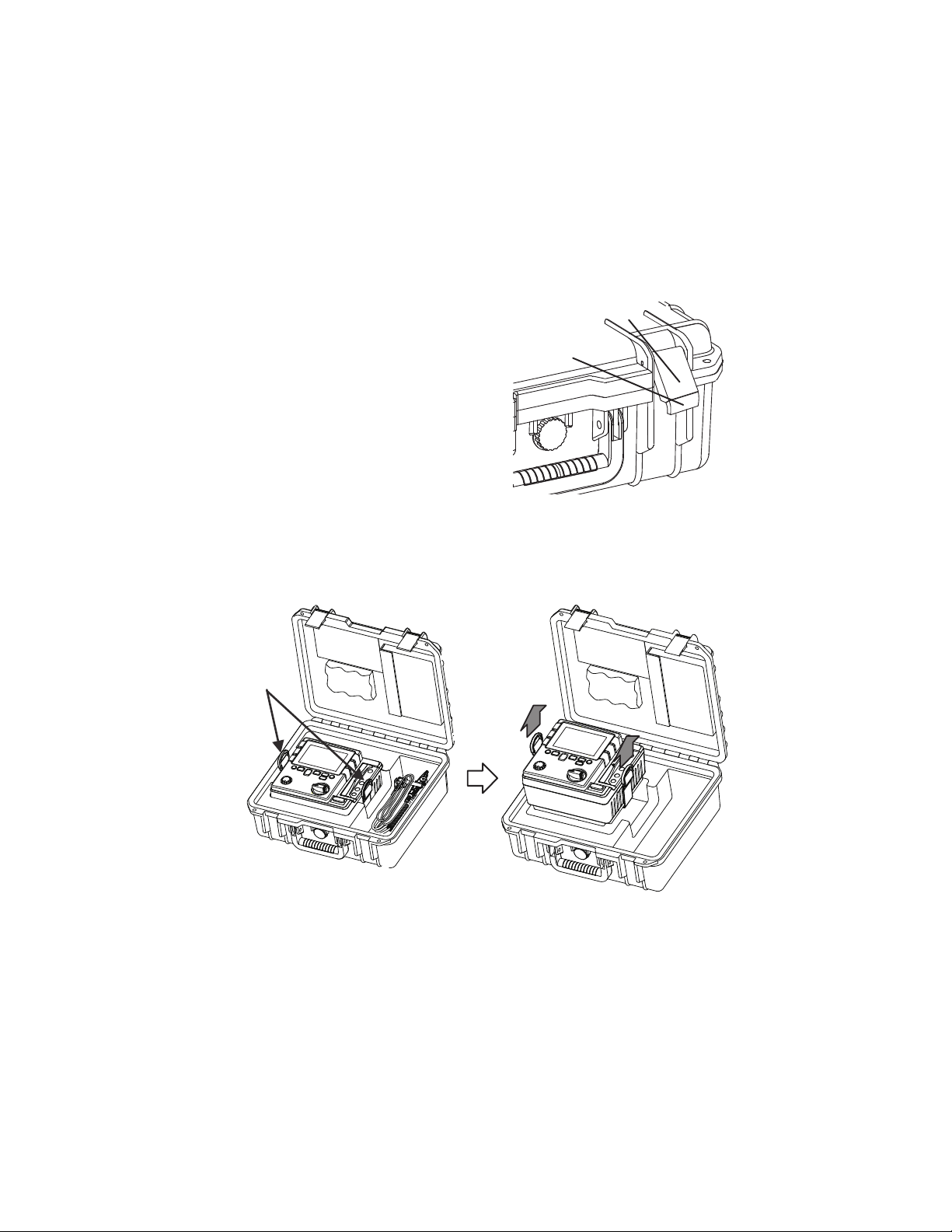
4-3 Opening and closing Hard case
Handles
The Latching device has two features: the larger portion which is the latch itself ①,
and the small latch release tab ② at the bottom of the latch.
1. To open, pull up the latch release tab
② in the direction of the arrow.
2. To close, lower the latch ① and press
until it snaps.
Never press the latch release tab ②
to close the latch as damage may result.
4-4 Taking out KEW3127 from the Hard case.
Grip the handles and pull upward to take out KEW3127 from the Hard case.
②
①
- 12 -
Find Quality Products Online at: sales@GlobalTestSupply.com
www.GlobalTestSupply.com
Page 16
5. Preparation for measurement
It is recommended to charge the battery with reference to 10.1 How to charge
battery described in the manual before stating to use with the instrument since
the battery voltage may be low due to self-discharge.
5-1 Checking the battery voltage
(1) Set the Range switch to any position other thanOFF.
(2)
When the battery mark shown at the upper left on the LCD is last 1 level ,
the batteries are almost exhausted.
Charge battery to perform further measurements.
The instrument operates properly even in such a low battery power condition
and it may not affect the accuracy.
When battery mark is empty , the battery voltage is below the lower limit
of the operating voltage. In such a condition, the accuracy isnt guaranteed.
Refer to10.1 How to charge battery and charge battery.
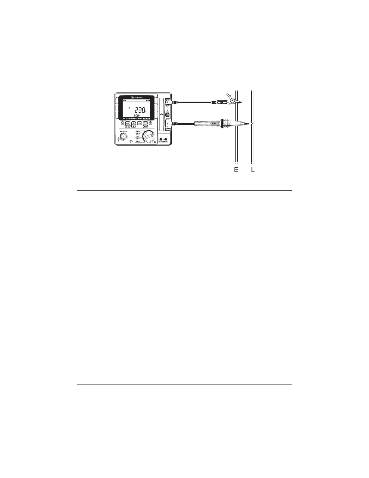
5-2 Connecting test leads
Insert the test lead firmly to the connector terminal on the instrument. Connect the
Line Probe(red) to the Line terminal, the Earth Cord(black) to the Earth terminal
and the Guard Cord(green) to the Guard terminal. (To establish guard is not
necessary, you do not have to connect the Guard cord.)
# DANGER
● Do not press the TEST button when the Range switch is at any position other
than OFF. High voltages are applied to the test leads and you may get
electrical shocks.
- 13 -
Find Quality Products Online at: sales@GlobalTestSupply.com
www.GlobalTestSupply.com
Page 17

6. Measurement
6-1 Mains disconnection check (Voltage measurement)
# DANGER
● Do not make measurement on a circuit in which the electric potential
exceeds 600V (voltage to ground) in order to avoid getting electrical shock.
In addition, do not use this instrument when the voltage to ground is 600V or
higher even the line voltage is 600V or less.
● Ensure that a measurement is performed at the secondary side of the circuit
breaker when testing the voltages of power lines, which has a large current
capacity, in order to avoid possible hazard to the user.
● Extra precaution shall be taken to minimize the possibility of shorting the
power line with the metal tip of test lead at voltage measurement. It may
cause personal injury.
● Do not start a measurement with the battery cover removed.
● Connect the Earth cord (black) to the Earth terminal of the circuit under test.
Set the Rage switch to any position other thanOFFposition.
Press the MODE button(
No need to press the Test button.
KEW3127 has an AC/DC auto-detect circuit and can measure DC voltage as well.
At DC voltage measurement, when applying positive voltage to the Line Probe
(red), positive value is displayed on the LCD.
) and selectVOLT mode.
Ensure that the circuit breaker of the circuit under test is turned off.
(1) Connect the Earth Cord (black) to the earth side of the circuit under test and
the Line Probe (red) to the line side respectively.
(2) Confirm that the voltage displayed on the LCD is Lo. If the display doesnt
show Lo, voltage is applied on the circuit under test. Check the circuit
under test again and turn off the circuit breaker.
- 14 -
Find Quality Products Online at: sales@GlobalTestSupply.com
www.GlobalTestSupply.com
Page 18
6-2 Insulation resistance measurement
# DANGER
● Confi rm that no electrical charge exists on the circuit under test before
measuring by using a high voltage detector.
● Put on a pair of insulated gloves for high voltage.
● In case the Range switch is set to Insulation resistance range, high voltage
is being applied to the tips of test leads and to the circuit under test
continuously while the Test button is kept pressed down. Be extremely
careful not to get electric shock.
● Do not start measurement with the battery cover removed.
● Never start measurement when thunder rumbling.
● Connect the Earth Cord (black) to the earth terminal of the circuit under test.
● When any mode other than VOLT mode is selected, live circuit warning
symbol appears on the LCD and the audible warning activates when a
voltage of 30V or higher is measured.
KEW3127 doesnt start a test, even the Test button is pressed down, if the
measuring voltage is 160V or higher: it starts a test if the measuring voltage
is under 160V upon a press of the Test button.
Prior to testing, ensure that the equipment under test is disconnected from
the mains supply and not energized in order to avoid possible electrical
hazards. This instrument may start a measurement for energized electrical
circuits. Be extremely careful not to get electrical shock.
- 15 -
Find Quality Products Online at: sales@GlobalTestSupply.com
www.GlobalTestSupply.com
Page 19

To check the insulation of electric equipments or electric circuits, measure
their insulation resistances by using this instrument. Ensure to check the
appropriate voltages to be applied to the equipment under test before starting
a measurement.
Note)
● KEW3127 may show unstable readings when the insulation resistance of the
equipment under test is not stable.
● Beep sound may be heard during insulation resistance measurement. But it
is not malfunction.
●It takes time to measure a capacitive load.
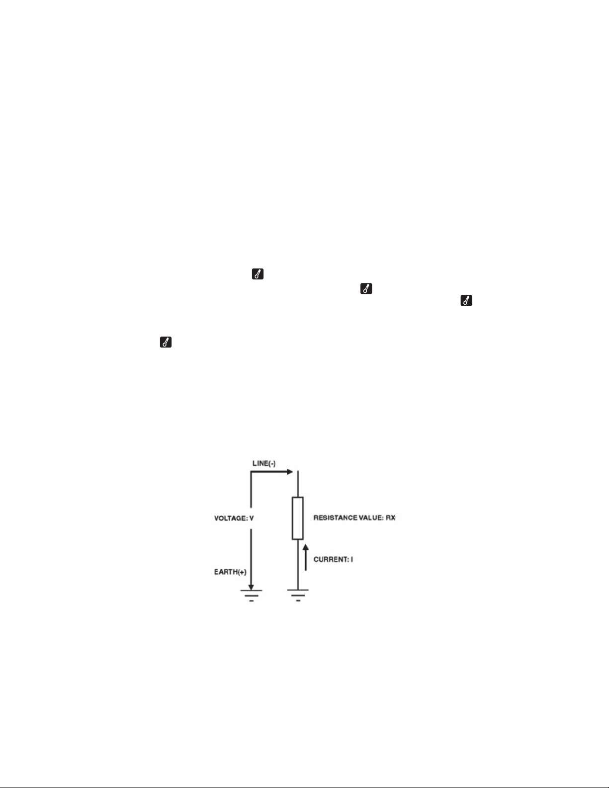
● At insulation resistance measurement, positive (+) voltage is outputted from
the Earth terminal and negative (-) voltage is outputted from the Line terminal.
Connect the Earth cord to the Earth (ground) terminal.
It is recommended to connect the positive(+) pole to the earth side when
measuring insulation resistance against the ground or when a part of the
equipment under test is earthed.
With this connection, smaller measured value can be obtained comparing
with other way round.
(1) Check the appropriate voltages to be applied to the circuit under test, and set
the Range switch to any desired insulation resistance range.
(2) Press the MODE button ( ) and select any of the following modes.
Mode Details
IR
PI/DAR Performs normal insulation resistance measurements (consistent
measurements)
(Auto-measurement and display of PI and DAR. )
SV Increases the set voltage by 20% every time when pre-set time
comes.
DD Calculates dielectric discharge based on the measured capacitance
of the measured object and residual current values after testing.
RAMP Increases the preset voltage gradually to detect insulation failures.
- 16 -
Find Quality Products Online at: sales@GlobalTestSupply.com
www.GlobalTestSupply.com
Page 20
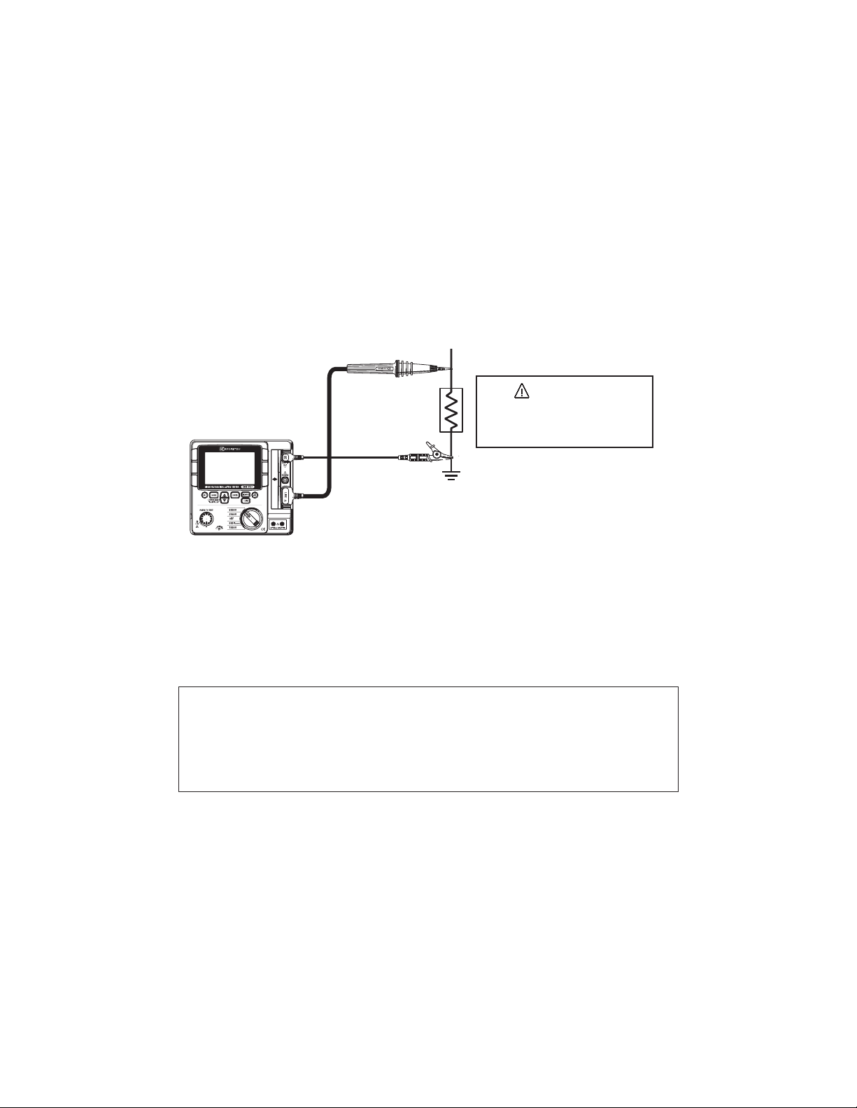
(3) Connect the Earth cord (black) to the Earth terminal of the circuit under test.
CAUTION
(4) Put the tip of the Line probe (red) to the circuit under test.
Then press the Test button. The buzzer sounds intermittently during
measurement when a range other than 500V(250V) range is selected.
(5) The measured value will be displayed on the LCD, and it remains displayed on
the LCD after a measurement.
Turn off the breaker of
the circuit under test.
(6) This instrument has Auto-discharge function. Keep the test leads connected
to the circuit under test and release the Test button when measurements end.
The auto-discharge function operates to discharge the electrical charges on
the circuit under test. Confi rm that the voltage monitor shows 0V.
# DANGER
●Do not touch the circuit under test immediately after testing.
Capacitance stored in the circuit may cause electric shock.
● Leave test leads connected to the circuit and never touch the circuit until the
discharge completes.
Auto-discharge function
This is a function to discharge capacitance stored in the circuit under test
automatically after testing. Discharge condition can be checked on the voltage
monitor. This function will be canceled when removing the test leads 2 sec. or
more before discharge completes.
- 17 -
Find Quality Products Online at: sales@GlobalTestSupply.com
www.GlobalTestSupply.com
Page 21
(7) Set the Range switch to OFF position, and remove test leads from the
instrument.
Note)
● The voltage warning mark stays on during a measurement and it blinks when
voltages of AC/DC 30V or higher exist on the circuit under test.
● When measuring low resistances (if currents larger than the rated current are
output) over a long period of time, KEW3127 consumes large power and will
overheat. When this happens, further tests are automatically inhibited and the
over-temperature symbol
be left cool down. Testing shall be resumed when symbol disappears.
Short-circuit currents at a start of measurement may get lower when the
symbol appears.
● Depending on the ambient temperature or measured resistances,
the symbol may appear and interrupt a PI measurement.
Principle of Insulation Resistance Measurement
Resistance value can be obtained by applying a certain high voltage to the
resistance (insulation resistance) and measuring the flowing current.
Resistance value = Voltage / Current
(RX = V / I)
appears on the display. The instrument must then
- 18 -
Find Quality Products Online at: sales@GlobalTestSupply.com
www.GlobalTestSupply.com
Page 22

6-3 About BREAKDOWN mode and BURN mode
Either Breakdown mode or Burn mode can be set for each measurement: IR
SV, DD, RAMP.
(1) Breakdown mode
When applied voltage decreases drastically due to breakdown or current sudden
increase caused by insulation degradation, KEW3127 stops measurement
automatically so as not to develop further damage.
KEW3127 continues measurement until an event of breakdown or current
sudden increase is detected.
(2) Burn mode
When Buren mode is selected, KEW3127 continues measurement even if
breakdown or current sudden increase event occurs. Keep checking the
damage degree of the breakdown point and fi nd the insulation failure point.
Testing performed in Burn mode is destructive.
PI/ DAR,
When breakdown occurs
and measurement stops,
breakdown mark blinks.
● When 250V Range has been selected, it is unable to select the Breakdown
mode.
- 19 -
Find Quality Products Online at: sales@GlobalTestSupply.com
www.GlobalTestSupply.com
Page 23

6-4 Continuous measurement
Press down and turn the Test button clockwise to lock it to perform a
continuous measurement of insulation resistance. After testing, turn the button
counterclockwise and set it to the initial position.
# DANGER
● Be extremely careful not to get electric shock as high voltage is present on
the tip of test leads continuously.
- 20 -
Find Quality Products Online at: sales@GlobalTestSupply.com
www.GlobalTestSupply.com
Page 24

PI/DAR Measurement
Resistance value
During measurement:
DAR or PI value
Time when
Output voltage
IR
Measurement Result
6-5 IR
At IRPI/DAR measurement, PI/ DAR values are automatically calculated and
displayed. During a measurement, values of current being measured and
capacitances measured at discharging after measurement are displayed.
PI/DAR
Output current
a test ends
(1) Setting items
Setting items for IRPI/DAR are as follows.
End of measurement:
Capacitance
● Measurement duration:
Measurement automatically stops when the preset time period passes.
● Output voltage :
For 2500V/ 5000V Range, voltage value is adjustable to – 20% of rated voltage,
can be set by 5%.
For 500V (250V) Range, either 500V or 250V is selectable.
● Breakdown/ Burn :
Either Breakdown or Burn mode is selectable. (For 250V, Burn mode only)
- 21 -
Find Quality Products Online at: sales@GlobalTestSupply.com
www.GlobalTestSupply.com
Page 25

(2) Setting procedures
Follow the procedures below
[Stand-by state]
Setting of Measurement duration (with UP/DOWN button ( ))
ENTER button ( )
Setting of Output voltage*1 (with UP/DOWN button ( ))
ENTER button ( )
Setting of Breakdown/Burn (with UP/DOWN button ( ))
ENTER button ( )
Setting is finished.
6-5-1 PI – Polarization index
This is to check a temporal increase of leakage currents flowing on insulations
and to confirm leakage currents arent increased as time passes.
PI is usually determined by the insulation resistances measured 1 min and 10
min after a measurement is started. PI is dependent on the shape of insulations
and influenced by moisture absorption, therefore, a check of PI is important to
diagnosis the insulation of cables.
ENTER button( )
(*1): 500V/2500V/5000V Range only
Insulation resistance
PI =
PI 4 or more 4 - 2 2.0 - 1.0 1.0 or less
Criteria Best Good Warning Bad
(10 min after a start of test)
Insulation resistance
(1 min after a start of test)
- 22 -
Find Quality Products Online at: sales@GlobalTestSupply.com
www.GlobalTestSupply.com
Page 26

6-5-2DAR - Dielectric Absorption Ratio
DAR measurement is almost same to PI measurement in a sense that they test
the time course of insulation. The only difference is that DAR measurement can
get result faster than the other.
Insulation resistance
DAR =
DAR 1.4 or more 1.25 - 1.0 1.0 or less
Criteria Best Good Bad
Note1: DAR time is selectable: 15 or 30 sec.
How to select:
① Keep the MODE button(
power on KEW3127. (DAR mark starts blinking.)
② Press the UP/DOWN button ( ) to switch 15 sec and 30 sec displayed at
the lower left on the LCD. Select the desirable one.
③ Press the ENTER button ( ) and confirm the selection.
Selected DAR time is saved and kept after the instrument is powered off. To
check the time currently selected, follow the step ① described as above.
(1 min after a start of test)
Insulation resistance
(15 or 30 sec min after a start of test)
) pressed down and rotate the Range switch to
*1
6-5-3 How to measure DAR/ PI
DAR and PI are measured automatically at continuous measurement of IRPI/DAR
mode. Set the Range switch to any range and measure the test object continuously.
- 1 min after a start of continuous measurement:
LCD shows DAR value.
- 10 min after a start of continuous measurement:
LCD shows PI value.
- 23 -
Find Quality Products Online at: sales@GlobalTestSupply.com
www.GlobalTestSupply.com
Page 27

When DAR/PI values are displayed as---:
DAR and PI values are determined by the methods 1. and 2. as described
above, therefore, they are displayed as --- when the measured insulation
resistances fall under any of following cases.
①measured value is 0.0MΩ
②measured value is OL
* OLis displayed when the measured value exceeds the upper limit of the
measuring range at each insulation resistance range.
Range Upper limit
250V 12GΩ
500V 120GΩ
1000V 240GΩ
2500V 1200GΩ
5000V 12TΩ
- 24 -
Find Quality Products Online at: sales@GlobalTestSupply.com
www.GlobalTestSupply.com
Page 28

6-5-4 How DAR/ PI values are displayed
(1) Start of test
No DAR/PI value,
DAR value is displayed.
(3) 10 min after the start of test
PI value is displayed.
values.
LCD shows DAR/PI values as shown below during measurements.
“---” is displayed.
(2) 1 min after the start of test
Press the UP/DOWN button
( )to switch DAR and PI
- 25 -
Find Quality Products Online at: sales@GlobalTestSupply.com
www.GlobalTestSupply.com
Page 29
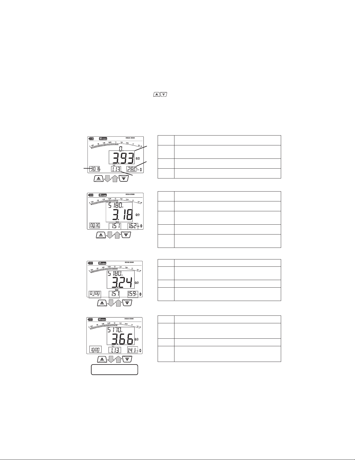
6-5-5 How to review the measured DAR/PI values
Return to (1)
Press the UP/DOWN button (
results are then displayed in following sequence. If the measurement ends earlier
than the intervals described in below (2), (3) or (4), blank displays arent shown
and returns to (1).
(1) Start of test
(B)
(D)
(A)
(C)
(2) 1 min after the start of test
) when measurements end. The measured
(A) Time when a test ends
Value measured at the end of test
(B)
(resistance value)
(C) DAR or PI value
(D) Capacitance
(2) 1 min after the start of test
(A) Elapsed time (15 or 30 sec)
Value measured 15 or 30 sec after a start
(B)
of test. (resistance value, output voltage)
(C) DAR value
Output Current measured 15 or 30 sec
(D)
after a start of test.
(3) 10 min after the start of test
(A) Elapsed time (1 min)
(B)
(C) DAR value
(D)
(4) Results at 10 min after a start of test
(A) Elapsed time (10 min)
(B)
(C) PI value
(D)
- 26 -
Value measured 1 min after a start of test.
(resistance value, output voltage)
Output Current measured 1 min after a
start of test.
Value measured 10 min after a start of
test. (resistance value, output voltage)
Output Current measured 10 min after a
start of test.
Find Quality Products Online at: sales@GlobalTestSupply.com
www.GlobalTestSupply.com
Page 30

6-6 SV Measurement (Step Voltage)
This is a test based on the principle that an ideal insulation will produce identical
readings at all voltages, while an insulation which is being over stressed, will show
lower insulation values at higher voltages. During the test, the applied voltage
incrementally steps by a certain voltage taking successive 5-time measurement.
Degradation of insulation may be doubt when insulation resistances become
lower at higher applied voltages.
SV Measurement Result
Output voltage
Resistance value
Time when
a test ends
During test: Output current
End of test: Capacitance
Present step
: 1st step
: 2nd step
・・・
: 5th step
(1) Setting items
Setting items for SV measurement are as follows.
(For SV measurement, 250V cannot be set at 500V (250V) Range.)
* Step time : Measurement duration per step.
* Breakdown/ Burn : Either Breakdown or Burn mode is selectable.
- 27 -
Find Quality Products Online at: sales@GlobalTestSupply.com
www.GlobalTestSupply.com
Page 31
Setting procedures
Follow the procedures below.
[Stand-by state]
Setting of Step time (with UP/DOWN button( ))
ENTER button( )
Setting of Breakdown/Burn (with UP/DOWN button( ))
ENTER button( )
Setting is finished.
6-7 DD Measurement (Dielectric Discharge)
This measurement method is usually used to diagnosis multi-layer insulations,
which requires the instrument to measure the discharge current and capacitance
of the measured object 1 min after the removal of the test voltage. This is a very
good diagnostic insulation test that allows deterioration and other problems voids
in the multiple insulations to be assessed.
Dielectric
Discharge
ENTER button( )
Current value 1 min after completing
measurement (mA)
=
Voltage value when a measurement
Complete (V) x Capacitance (F)
DD 2.0 or less 2.0 - 4.0 4.0 - 7.0 7.0 or more
Criteria Good Warning Poor Very Poor
This criteria is a guide and could be slightly changed and be adapted to particular
objects under test based on practical experience of the users. This method has
been established to test high voltage generators installed in electric power plants
in the Europe countries.
- 28 -
Find Quality Products Online at: sales@GlobalTestSupply.com
www.GlobalTestSupply.com
Page 32
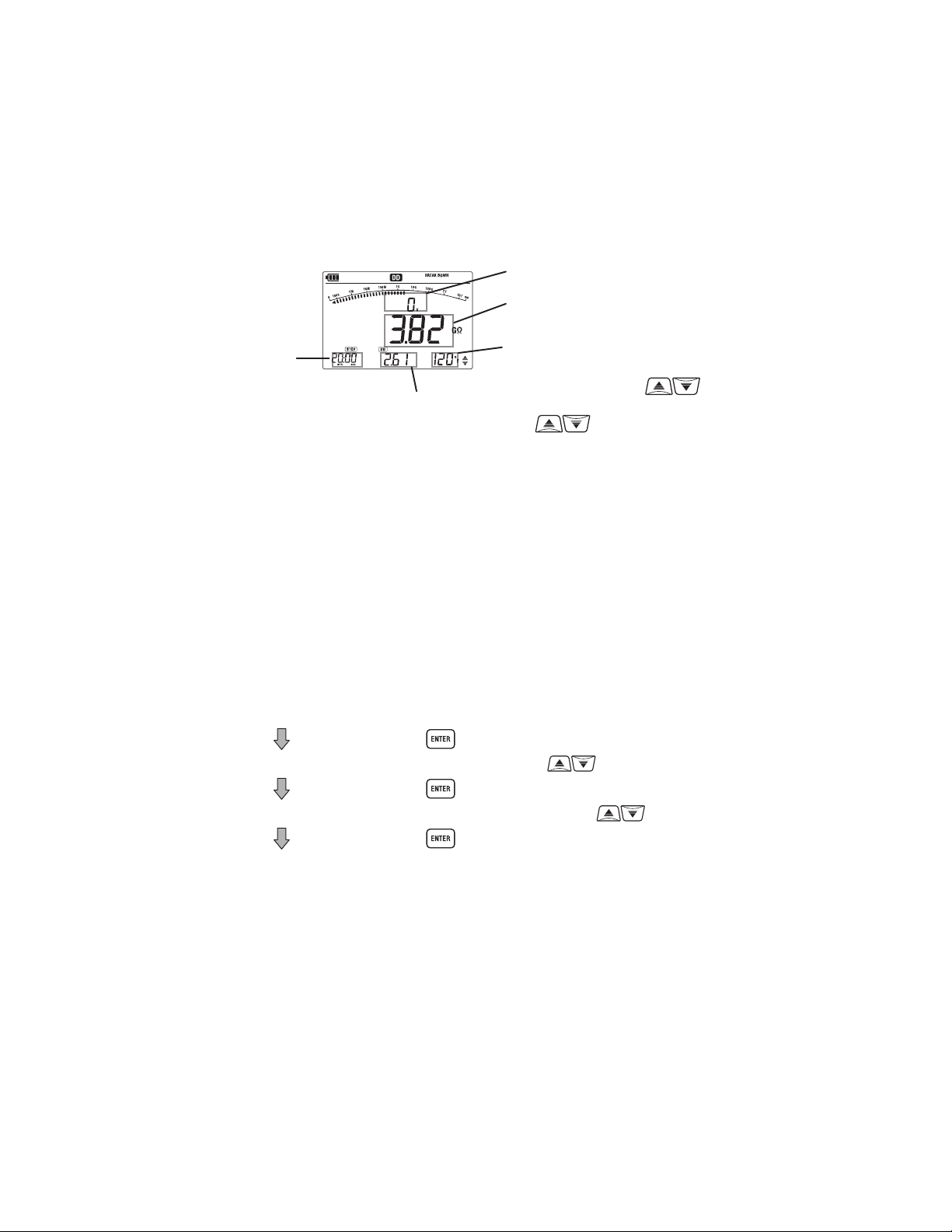
DD Measurement Result
Output voltage
Resistance value
Time when
a test ends
(1) Setting items
Setting items for DD measurement are as follows.
(For DD measurement, 250V cannot be set at 500V (250V) Range.)
* Step time : Measurement duration per step.
* Breakdown/ Burn : Either Breakdown or Burn mode is selectable.
(2) Setting procedures
Follow the procedures below.
[Stand-by state]
Setting of Step time (with UP/DOWN button( ))
ENTER button( )
Setting of Breakdown/Burn (with UP/DOWN button( ))
ENTER button( )
Setting is finished.
DD or Voltage value
(switchable with UP/DOWN button )
ENTER button( )
Discharge current or
Capacitance (switchable with
UP/DOWN button )
- 29 -
Find Quality Products Online at: sales@GlobalTestSupply.com
www.GlobalTestSupply.com
Page 33
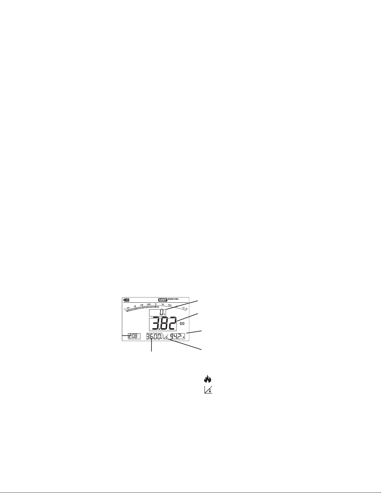
6-8 Ramp Measurement
Voltage used in Step voltage test is raised in steps but that used in Ramp
measurement is gradually raised. Therefore, Ramp measurement is useful to fi nd
the points of insulation failure without causing serious damages. This enables
you to locate a fault, such as pinholes in windings, by seeing a spark or a wisp of
smoke.
KEW3127 displays the breakdown voltage value when insulation breakdown
occurs in load.
* Breakdown mode
When a breakdown occurs, KEW3127 stops measurement and displays the
voltage which caused breakdown. When no breakdown is detected, voltage is
raised till it reaches to the preset voltage value.
* Burn mode
KEW3127 continues measurement, even if a breakdown is detected, until applying
voltage reaches to the preset value. Breakdown voltage will be displayed after a
measurement.
Note: Ensure that the object under test is completely discharged before performing
a Ramp measurement.
Ramp measurement result
Time when
a test ends
Breakdown voltage
(Voltage value when breakdown
occurred.)
- 30 -
Output voltage
Resistance value
End of test:
Output current
Breakdown mark
(Either following marks
blinks when breakdown
occurs.)
: Burn mode is set
:Breakdown mode is set.
Find Quality Products Online at: sales@GlobalTestSupply.com
www.GlobalTestSupply.com
Page 34

(1) Setting items
Setting items for RAMP measurement are as follows.
(For RAMP measurement, 250V cannot be set at 500V (250V) Range.)
* Speed of voltage rise: Voltage rise per minute.
* Breakdown/ Burn : Either Breakdown or Burn mode is selectable.
(2) Setting procedures
Follow the procedures below.
Output voltage rate can be set between 100V/min and 9000V/min.
[Stand-by state]
Setting of Voltage rise speed (with UP/DOWN button( ))
ENTER button( )
Setting of Breakdown/Burn (with UP/DOWN button( ))
ENTER button( )
Setting is finished.
ENTER button( )
- 31 -
Find Quality Products Online at: sales@GlobalTestSupply.com
www.GlobalTestSupply.com
Page 35
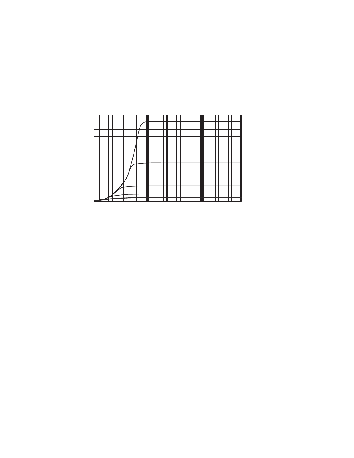
6-9 Voltage characteristics of measuring terminal
KEW3127 Output characteristics (IR
6000
PI/DAR
mode)
5000V range
5000
4000
3000
2000
Output Voltage(V)
1000
2500V range
1000V range
500V range
0
0.1
MΩ1MΩ10MΩ
Insulation Resistance
100MΩ1000
MΩ
10
GΩ
100GΩ1000
250V range
GΩ
* for 10sec after a start of test
6-10 Use of Guard terminal
When measuring the insulation resistance of a cable, leakage current flowing on
the surface of cable jacket and the current flowing inside the insulator are mixed
and may cause error in insulation resistance value. In order to prevent such error,
wind a conductive wire around the point where leakage current flows.
Then connect it to the Guard terminal as shown in the figure on the next page. This
is to move out the surface leakage resistance of the cable insulation to measure
only the volume resistance of insulator. Make sure to use the Guard cord supplied
with this instrument to connect the instrument to Guard terminal.
- 32 -
Find Quality Products Online at: sales@GlobalTestSupply.com
www.GlobalTestSupply.com
Page 36

L
Conductor
Power supply
Indicator
(Insulation resistance tester)
Leakage current
G
E
Insulation
Protective wire
Cable with sheath
6-11 Filter function
KEW3127 has Filter function. Filter Mode is effective to reduce the variations in
readings due to external influences during high resistance measurements. The
filter type is Low pass filter with cut off frequency of 0.3Hz.
Press the FILTER button(
) to enable the Filter function. The Filter mark then
appears on the LCD. To check sudden variations in resistances, ensure that the
Filter mode is turned off.
6-12 Backlight function
This function to facilitate working at dimly illuminated location or at nighttime
work. The backlight doesnt work when the Range switch is set toOFF. It
automatically turns off 1 min after the last key operation; this feature is disabled
while a measurement is processed.
6-13 Auto-power-off function
The instrument automatically turns off approx. 10 min. after the last switch
operation. To restore from the auto power off status, set the Range switch to OFF
position once and then set it to any desirable range.
- 33 -
Find Quality Products Online at: sales@GlobalTestSupply.com
www.GlobalTestSupply.com
Page 37

7. Memory Function
7-1 Function Details
Measurement data of insulation resistance can be saved in the internal memory
of KEW3127.
Following data can be saved.
1. LOGGING: Measuring data is saved every second.
2. MEMORY: Data is saved at the end of measurement.
(1) Max number of file
1. LOGGING: Max 10 files
* Up to 100min in total
* Max recording time per file: 90min
2. MEMORY: Max 32 files
(2) Parameters to be saved
Following parameters will be saved. (common for LOGGING and MEMORY)
1. In all modes: Saved time & date, measured values (resistance, current,
voltage), capacitance
2. IRPI/DAR mode: PI/ DAR value
DD mode: DD value
Ramp mode: Breakdown voltage
- 34 -
Find Quality Products Online at: sales@GlobalTestSupply.com
www.GlobalTestSupply.com
Page 38

7-2 How to save data
Follow the procedures below to save the measured data.
Pressing the ESC button (
), during operation, returns to the previous screen.
(1) Stand-by state
Data save in the MEMORY mode shall
be done after fi nishing a measurement.
(while the result is being displayed on
the LCD.)
(2) Press the MEMORY button.
(3)
Select eitherMEMORYor LOGGING
with the UP/DOWN button ( ).
Blink
(4) Press the ENTER button.
When selecting When selecting LOGGING:
MEMORY:
(5) Saving completes and
back to stand-by state.
(5) Stand-by state
“LOGGING”
mark appears
(6) Press the TEST button.
(7) Measurement and logging start.
- 35 -
Find Quality Products Online at: sales@GlobalTestSupply.com
www.GlobalTestSupply.com
Page 39
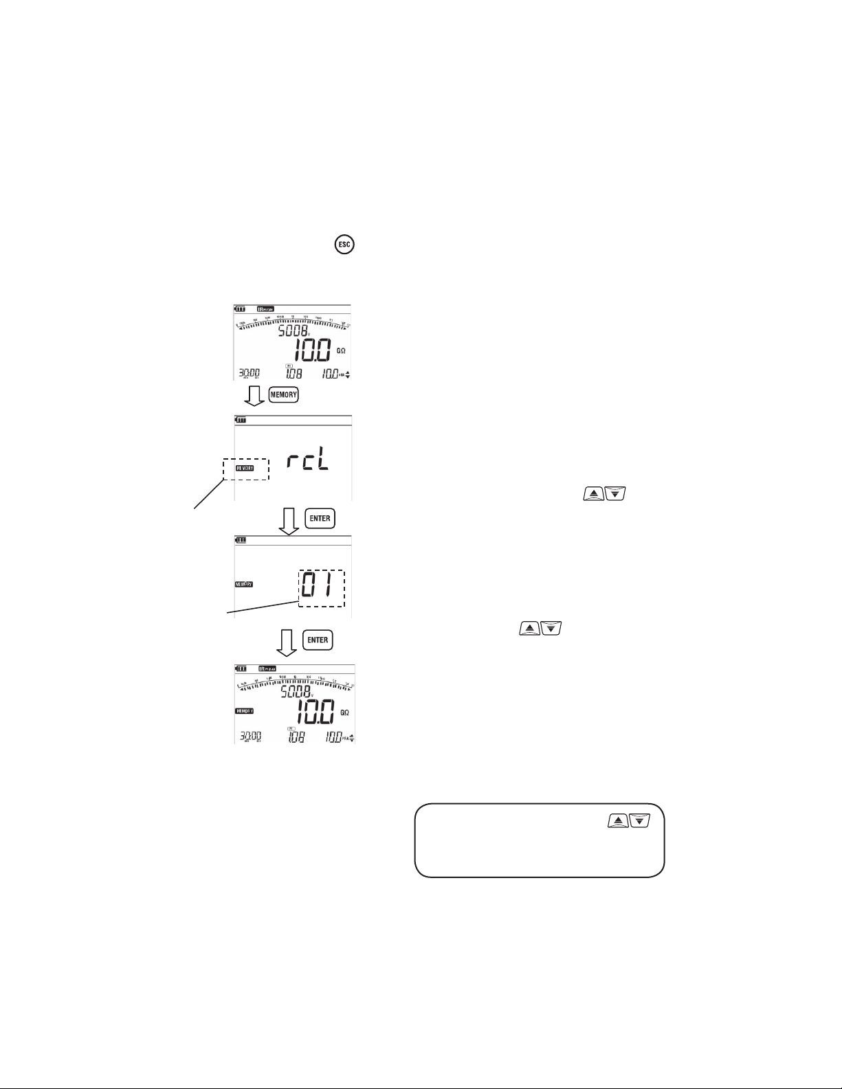
7-3 How to recall saved data
Follow the procedures below to recall the saved data.
Pressing the ESC button (
), during operation, returns to the previous screen.
(1) Stand-by state
(1s or longer)
(2) Press the MEMORY button for 1 sec or
longer.
(3)
Select eitherMEMORYor LOGGING
with the UP/DOWN button ( ).
Blink
(4) Press the ENTER button.
Memory
No.
(5) Select a memory number with the UP/
DOWN button( ).
(6) Press the ENTER button.
(7) Saved data will be displayed. If the
recalled data is logging data, the latest
data will be displayed.
Press the UP/DOWN button ( )
to switch the display of current value
and capacitance value.
- 36 -
Find Quality Products Online at: sales@GlobalTestSupply.com
www.GlobalTestSupply.com
Page 40
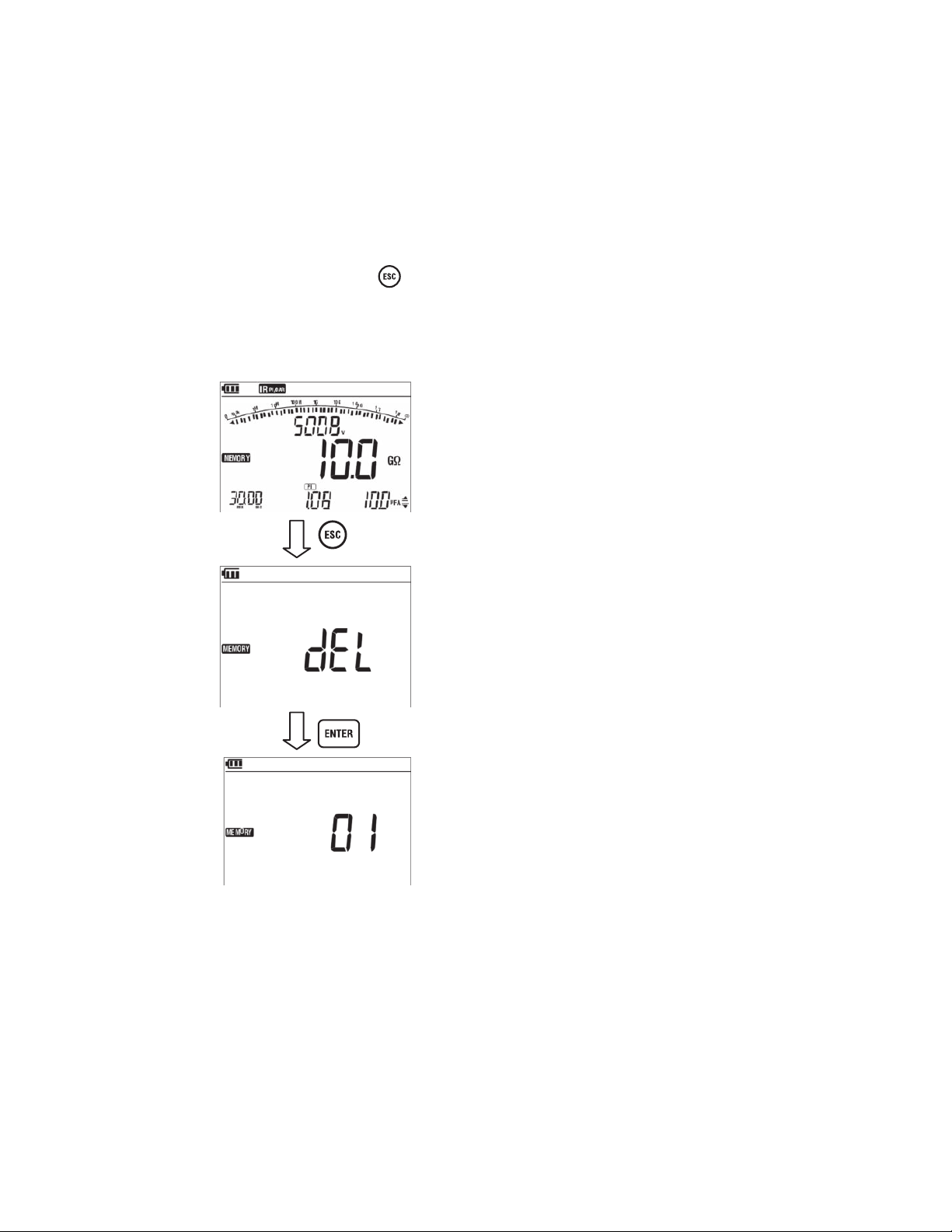
7-4 How to delete data
Follow the procedures below to delete the saved data.
Pressing the ESC button (
Recall and display the data which one wishes to delete. (See clause 7-3 How to
recall the saved data.)
), during operation, returns to the previous screen.
(1) Recall and display the saved data.
(1s or longer)
(2) Press the ESC button for 1 sec or
longer.
(3) Confi rmation screen is displayed.
(4) Press the ENTER button to delete the
data.
(5)
Return to Memory No. selection screen.
- 37 -
Find Quality Products Online at: sales@GlobalTestSupply.com
www.GlobalTestSupply.com
Page 41
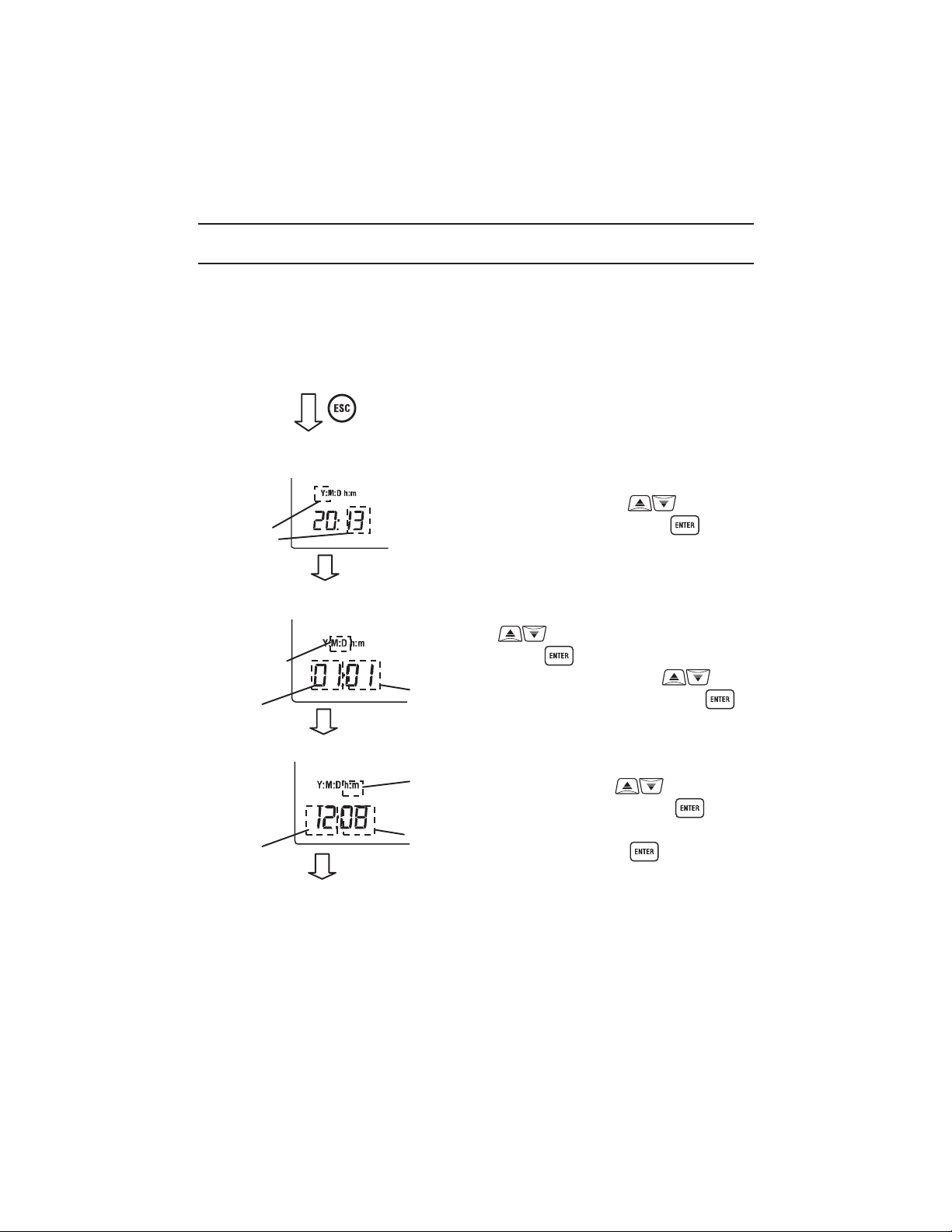
8.Clock Setting
Follow the procedures below and adjust the internal clock of KEW3127. To confi rm
the clock time, use the PC application KEW Windows or repeat the following
steps.
[Power-off state]
1. Adjust year.
Blink
2. Adjust Month & day.
Blink
Month
3. Adjust Hour &Minute.
Hour
+ Power on
Day
Blink
Minute
(1) Hold down the ESC button and power
on the instrument.
(2) At the lower left on the LCD, Y
starts blinking. Adjust the year with the
UP/DOWN button ( ), and then
press the ENTER button ( ).
(3) ThenM:Dstarts blinking. Adjust
the month with the UP/DOWN button
( ), and then press the ENTER
button ( ). Likewise, adjust day with
the UP/DOWN button ( ), and
then press the ENTER button ( ).
(4) The last parameter,h:mstarts
blinking. Adjust hour with the UP/
DOWN button ( ), and then
press the ENTER button ( ).
Do the same to set minute and press
the ENTER button ( ).
4. Clock setting
is finished.
Find Quality Products Online at: sales@GlobalTestSupply.com
www.GlobalTestSupply.com
(5) Now clock setting completes.
Power off the instrument.
- 38 -
Page 42

9. Communication Function/ Software
9-1 KEW3127 Settings
The PC software application enables analysis of the saved data from PC.
KEW3127 has following two kinds of communication methods.
(1)Bluetooth
(2)MODEL8212USB
Following can be done via PC communication.
(use software KEW Windows for KEW3127.)
* Downloading a file in the internal memory of the instrument to a PC
* Making settings for the instrument via PC.
* Displaying the measured results as a graph and saving them in realtime.
Communications with a PC cannot be established while operating KEW3127.
(e.g.: while setting measurement time, output voltage or saving data.)
When the instrument is out of the range of Bluetooth or MODEL8212 USB is
disconnected and the data download is failed, power off the instrument and on
again and retry the download.
- 39 -
Find Quality Products Online at: sales@GlobalTestSupply.com
www.GlobalTestSupply.com
Page 43
Instrument setting
Follow the procedure below and select the communication method on KEW3127
before starting PC communication.
1. [Power-off] state
+ Power on
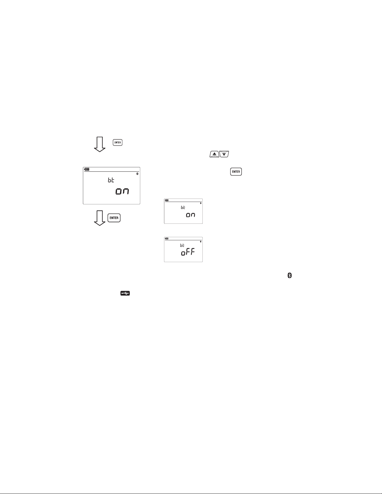
2. [Setting]
(1) Hold down the ENTER button and power
on the instrument.
(2) LCD shows BT on. Use the UP/DOWN
button (
communication method and press the
ENTER button ( ).
) and select a desirable
* Selecting Bluetooth: set to “bt on”
3. Setting is finished.
・When KEW3127 communicates via Bluetooth, Bluetooth mark( )is
displayed on the LCD. When KEW3127 communicates via MODEL8212USB,
USB mark( ) is displayed on the LCD.
* Selecting MODEL8212USB: set to “bt off”
● Using optional MODEL 8212 USB
(1) Connect MODEL 8212 USB to the USB port on a PC. (Refer to the instruction
manual for MODEL 8212 USB and install the special driver.)
(2) Connect MODEL 8212 USB and KEW3127 as illustrated below. Further
instructions for use are in the HELP for KEW Windows for 3127.
- 40 -
Find Quality Products Online at: sales@GlobalTestSupply.com
www.GlobalTestSupply.com
Page 44

Connect MODEL 8212 USB here.
● Interface
(1) Bluetooth
Bluetooth Ver2.1+EDR (Class2)
Compliant profi le: SPP
(2 )MODEL8212USB
Communication method: USB Ver1.1
● Software
KEW Windows for KEW3127 (Download this software from our homepage.
Refer to9-2 How to install the Software.)
● System Requirements
* OS (Operation System)
Windows7/VISTA/XP(CPU: Pentium 4 1.6GHz or more)
* Memory
512Mbyte or more (for Windows XP), 1Gbyte or more (for Windows 7/ Vista)
* Display
1024 × 768 dots, 65536 colors or more
* HDD (Hard-disk space required)
1Gbyte or more (including Framework)
* .NET Framework (3.5 or later)
After connecting MODEL 8212
USB. (side view)
● Trademarks
* Windows® is a registered trademark of Microsoft in the United States.
* Pentium is a registered trademark of Intel in the United States.
* Bluetooth is a registered trademark of Bluetooth SIG.
- 41 -
Find Quality Products Online at: sales@GlobalTestSupply.com
www.GlobalTestSupply.com
Page 45

9-2 How to install the Software
Followings are the instructions to install the softwareKEW Windowsand
KEW Windows for KEW3127.
(1) Before installing the software, followings shall be checked.
● To prepare your system to install this software, please close all open
programs.
● Be sure NOT to connect the instrument with USB until install is completed.
● Installation shall be done with administrative right.
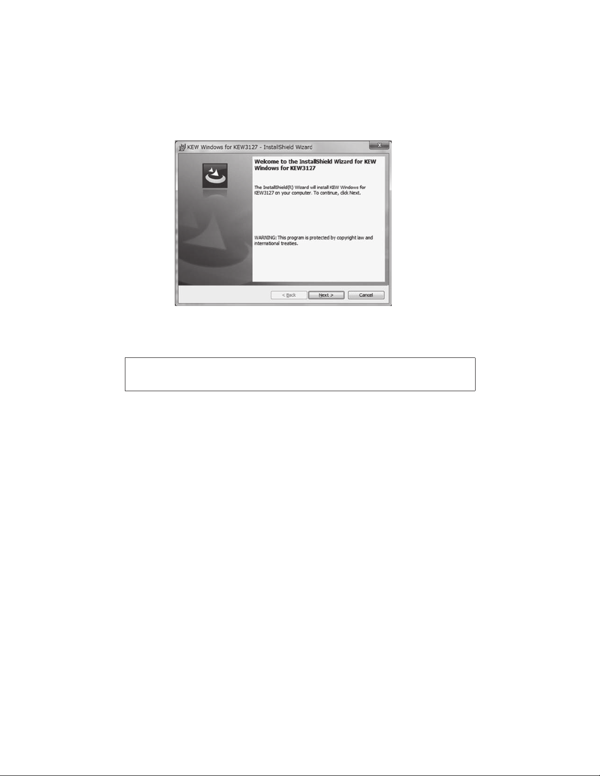
(2) Download the file "KewWin3127Inst_eng.exe"
(3) Run the "KewWin3127Inst_eng.exe".
Then following window appears. ClickNext
Read through and understand the License Agreement, and checkI accept…..
Then click Next.
- 42 -
Find Quality Products Online at: sales@GlobalTestSupply.com
www.GlobalTestSupply.com
Page 46

Enter the user information and specify the location to where install the software.
Then click Next.
Confirm the information on install, and click Install to start installing.
- 43 -
Find Quality Products Online at: sales@GlobalTestSupply.com
www.GlobalTestSupply.com
Page 47

Click Finish when install completes.
An installation ofKEW Windows for KEW3127is followed by the installation
of KEW Windows.
- 44 -
Find Quality Products Online at: sales@GlobalTestSupply.com
www.GlobalTestSupply.com
Page 48
● To install the KEW Windows for KEW3127", you can follow the same
installation procedure described for KEW Windows.
If you need to remove this software, use the Add/Remove Programs tool in
the Control Panel.
9-3 How to start KEW Windows for KEW3127
● Start and Quit
Start the software by; 1) clicking the icon for [KEW Windows] on the desktop,or
2) clicking [Start] → [Program] → [KEW] → [KEW Windows]. Then the KEW
products, which have been installed in the KEW Windows, are listed up.
Select the KEW3127 on the list, and then click Next. Then a main
menu for KEW Windows for KEW3127 appears. Click [Data Download] or
[Instrument Setting].
- 45 -
Find Quality Products Online at: sales@GlobalTestSupply.com
www.GlobalTestSupply.com
Page 49

- 46 -
Find Quality Products Online at: sales@GlobalTestSupply.com
www.GlobalTestSupply.com
Page 50

9-4 Features of KEW Smart
Remote checking of measurements is possible without accessing KEW3127
using the special Android application KEW Smart.
The application KEW Smart is available on download site for free. (An
Internet access is required.)
Please note that communication charge is incurred separately for downloading
applications and using special features of them. For your information, KEW
Smart is provided on-line only.
Main features:
● Checking of measurement
Measurements can be displayed in graphic or numeric forms on
Android devices in real-time.
● Checking of KEW3127 setting
Settings of KEW3127 can be checked.
● Saving measured results
Results can be converted and saved in PDF.
● Transmitting measurement data
Saved data can be transmitted to a PC. Details can be found in the HELP for
KEW Smart.
Cautions:
● Battery level of KEW3127 is not shown on Android devices. Ensure that the
battery level of KEW3127 is sufficient before starting to perform measurements
using these features. Charge battery if necessary.
● Remote control, such as switching ranges of KEW3127, from Android devices
is not possible.
- 47 -
Find Quality Products Online at: sales@GlobalTestSupply.com
www.GlobalTestSupply.com
Page 51

10.Battery Charging and Replacement
10-1 How to charge battery
# DANGER
Use only the Power adapter supplied with this instrument.
Connect the Power adapter to a mains socket outlet. The mains supply voltage
must not exceed AC240V.
Handling and storage instructions specifi ed by the battery manufacturer should
be observed.
# WARNING
Never attempt to make any measurement if any abnormal conditions, such
as a break on the Power adapter or exposed metal parts are present on the
instrument. When unplugging the Power adapter from the mains socket outlet,
do so by removing the plug fi rst and not by pulling the cord.
(1) Set the Range Switch to the OFF position.
(2) Confi rm a battery is installed in the instrument.
(3) Slide the shutter of the terminal to the measurement terminal side and connect
the Power Adapter.
(4) LED Status Indicator fl ashes in red and the Battery Mark also fl ashes on the
LCD.
(5) The indicator lights up in green and the Battery Mark on the LCD stops fl ashing
and lights up. (Battery charge completes in about 8 hours.)
* KEW3127 cannot perform measurement while charging battery.
* Battery life and how many times can be
charged are depended on conditions of use
and environment.
* Storing rechargeable lead-acid batteries in a
low-charged state could lead to reduced life
and/or damage. When storing the battery for
a long period, check and charge the battery
at regular intervals.
-50-
- 48 -
Find Quality Products Online at: sales@GlobalTestSupply.com
www.GlobalTestSupply.com
Page 52
10-2 How to replace battery
# DANGER
● Never open the battery compartment cover while making measurement.
● To avoid possible electric shock, disconnect the test lead and Power Adapter
from the instrument before replacing battery. After replacing batteries, make
sure to tighten up the screw for battery compartment cover.
# WARNING
● Always use 12V5Ah Lead acid battery PXL12050 or equivalent.
# CAUTION
● Install battery with correct polarity.
● Followings may cause battery liquid leak, heating, explosion or damage to
Case resulting injury.
* short-circuiting the positive and negative terminals,
* putting close to fi re, or
* disassembly or modifi cation.
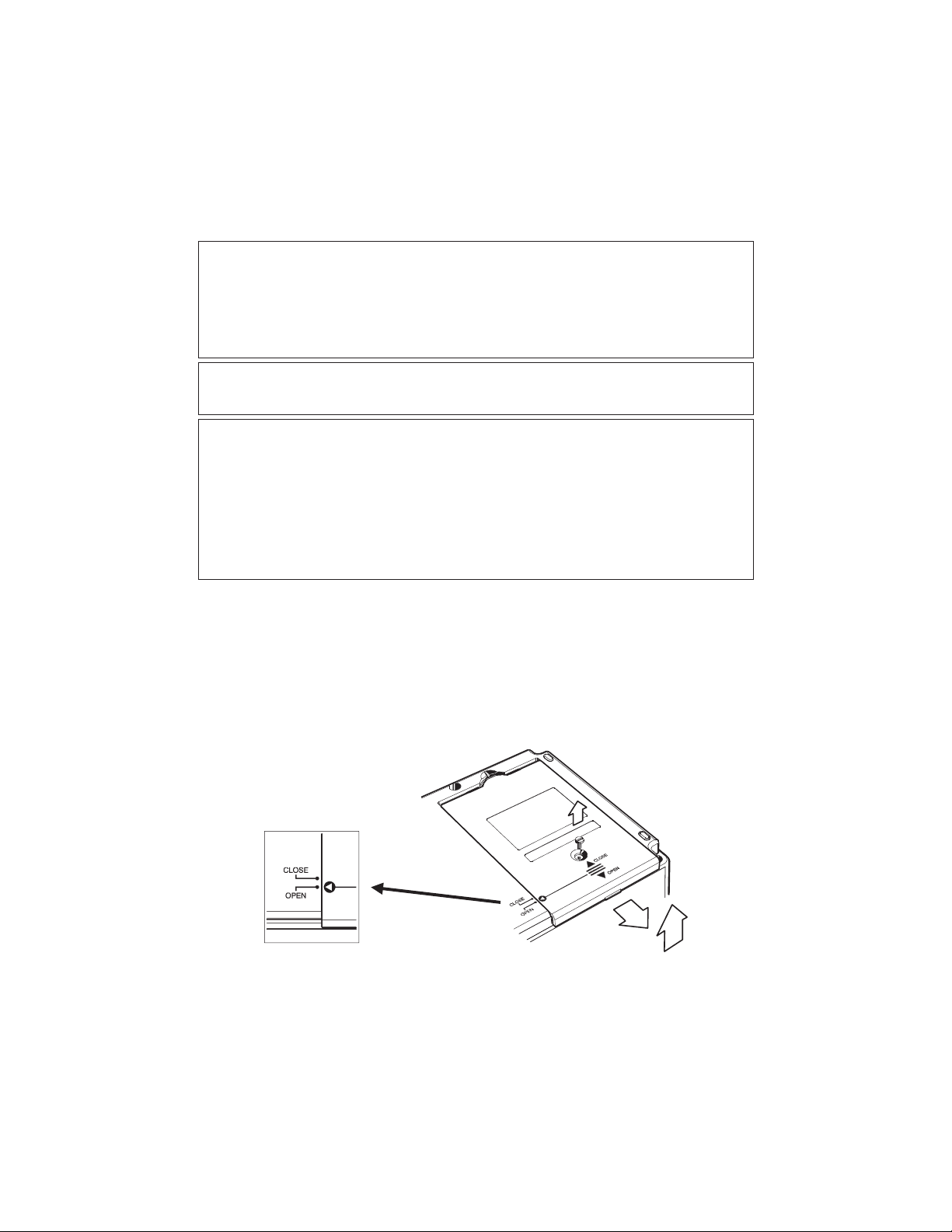
(1) Set the Range switch to OFF position, and remove the test leads and
power adapter from the instrument.
(2) Unscrew and slide to remove the battery compartment cover on the side face
of the instrument. (Match the arrow mark on the battery compartment cover
with the engraved OPEN on the instrument case.)
Attention should be paid not to lose screws.
- 49 -
Find Quality Products Online at: sales@GlobalTestSupply.com
www.GlobalTestSupply.com
Page 53

Pull up the battery as below and disconnect the red and black cables. (Pull the
(3)
positive and negative connectors upwards and disconnect them from the battery.)
Pull the connector upwards.
(4) Replace the old battery with the new one (lead-storage battery PXL-12050:
12V5Ah). Ensure that the connectors are properly attached and the metal
terminals of battery are not deformed, and then install the battery observing
the correct polarities.
(5) Slide and attach the battery compartment cover and tighten it with screw.
Ensure that the arrow mark on the battery compartment cover matches with
theCLOSEmark on the instrument case.
- 50 -
Find Quality Products Online at: sales@GlobalTestSupply.com
www.GlobalTestSupply.com
Page 54

11.Accessories
11-1 Metal parts for Line Probe, and replacement
# DANGER
In the electrical environment of CAT.II or higher, MODEL8255 should be attached
and used with the test lead. With the large exposed metal parts of MODEL8254
and 8019, the equipment under test may be shorted. It may result in failure of
the equipment under test and cause fire or lead to fatal or serious injury.
(1) Tip metal parts
MODEL8255: Standard Prod (straight type, with molded parts)
MODEL8254: Straight Type Prod
MODEL8019: Pickel Type Prod
To be used to hook the instrument.
(2) How to replace it
Turn the Line probe counterclockwise to remove the attached tip metal. Put
the tip metal you want to use to the hexagon socket and turn it to clockwise
together with the tip of probe, and tight up screws.
MODEL8255
MODEL8254
Male Screw
Hexagon Socket
MODEL8019
- 51 -
Find Quality Products Online at: sales@GlobalTestSupply.com
www.GlobalTestSupply.com
Page 55
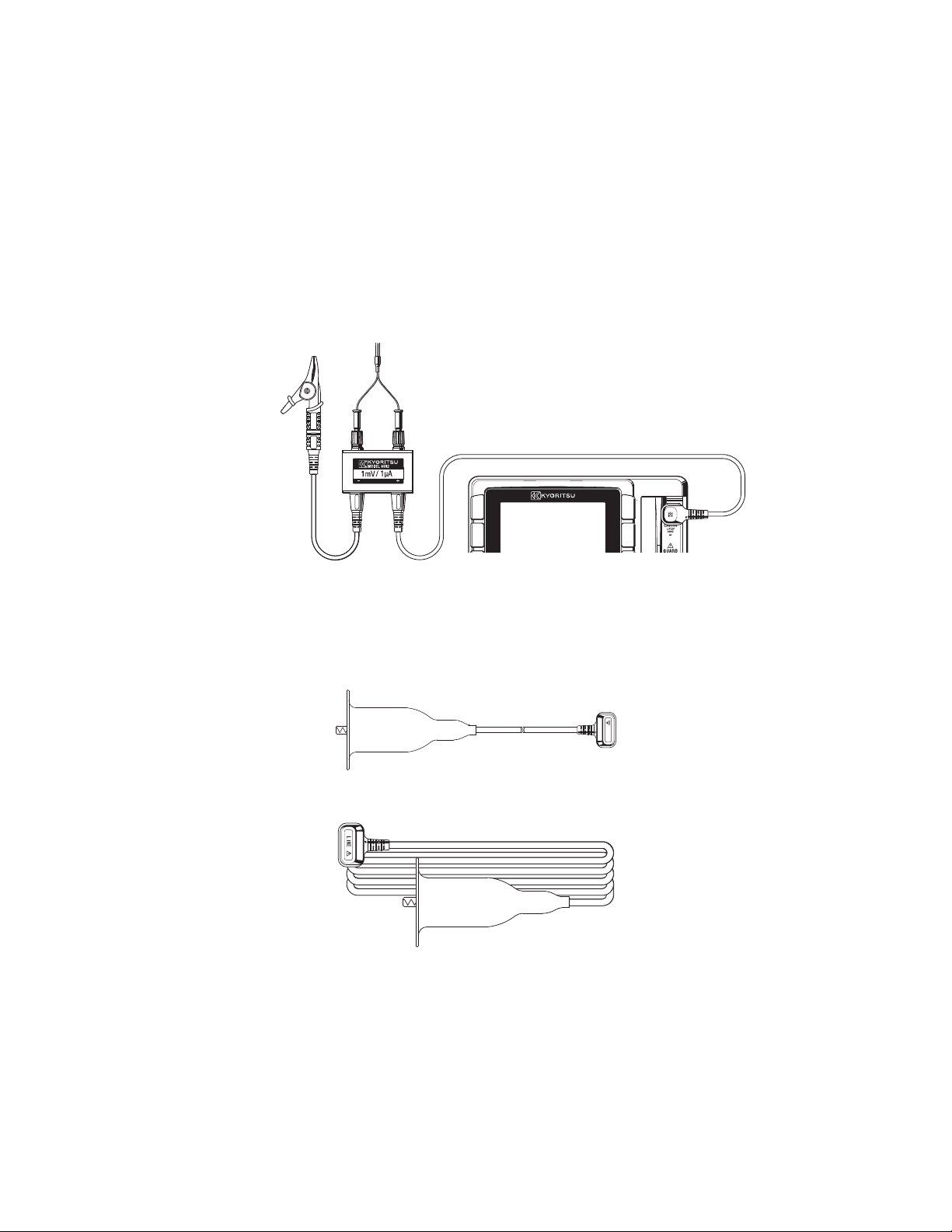
11-2 How to use the adaptor for recorder
MODEL8302 is the adaptor for recorder (option) for output current measurement.
Connect it as shown in the below fi gure.
Output is DC1mA when current of 1μA is fl owing.
To recorder
-
+
To shield
or Earth
* MODEL8302 can measure currents up to 2mA.
11-3 Line probe with alligator clip(optional accessory)
(1) MODEL7168A Line probe with alligator clip
(2) MODEL7253 Long Line probe with alligator clip (15m)
LINE
- 52 -
Find Quality Products Online at: sales@GlobalTestSupply.com
www.GlobalTestSupply.com
Page 56

12. Disposing the Product
Waste Electrical and Electronic Equipment (WEEE), Directive 2002/96/EC
This Product complies with the WEEE Directive (2002/96/EC) marking requirement.
The affixed product label (see below) indicates that you must not discard this
electrical/electronic product in domestic household waste.
Product Category
With reference to the equipment types in the WEEE directive Annex 1, this product
is classified as a Monitoring and Control instrumentation product.
Disposing lead-storage batteries
When you throw away the batteries, be sure to cover their positive and negative
terminals and always observe local laws and regulations.
Insufficient insulation of the terminals may cause explosion or fire because
electrical energies remain in lead-storage batteries after use.
- 53 -
Find Quality Products Online at: sales@GlobalTestSupply.com
www.GlobalTestSupply.com
 Loading...