

Page 1

Instruction manual
INSULATION - CONTINUITY TESTER
KEW 3021A・3022A・3023A
Find Quality Products Online at: sales@GlobalTestSupply.com
www.GlobalTestSupply.com
Page 2

Contents
1.Safety warnings ……………………………………………………1
2.Features ……………………………………………………………4
3.Specification ………………………………………………………5
4.Instrument layout …………………………………………………9
5.Preparation for measurement ……………………………………10
5 − 1 Test lead connection ………………………………………10
5 − 2 Checks on Test lead and Fuse …………………………10
6.Measurement ……………………………………………………11
6 − 1 Voltage measurement(Mains disconnection check) …11
6 − 2 Insulation resistance measurement ……………………11
6 − 3 Continuous measurement ………………………………14
6 − 4 Output voltage characteristics ……………………………14
6 − 5 Measurement of resistance (Continuity check) ………15
6 − 6 Backlight function …………………………………………16
6 − 7 Auto-power-off ……………………………………………16
7. Functions keys ……………………………………………………17
7 − 1 Comparator function ………………………………………17
7 − 2 Memory (save) function …………………………………17
8.Fuse & Battery replacement ……………………………………18
8 − 1 Battery replacement ………………………………………18
8 − 2 Fuse replacement …………………………………………19
9.Notes on Housing case and accessories ………………………19
9 − 1 Case lid ……………………………………………………19
9 − 2 Neck strap and Cord case ……………………………20
9 − 3 Test prods and replacement …………………………20
9 − 4 Adaptors for the Earth cord and replacement …………20
10.Cleaning of the instrument ……………………………………21
11.Servicing …………………………………………………………21
Find Quality Products Online at: sales@GlobalTestSupply.com
www.GlobalTestSupply.com
Page 3

1.Safety warnings
○ This instrument has been designed, manufactured and tested
according to IEC 61010-1: Safety requirements for Electronic
Measuring apparatus, and delivered in the best condition after passed
the inspection. This instruction manual contains warnings and safety
rules which must be observed by the user to ensure safe operation of
the instrument and retain it in safe condition. Therefore, read through
these operating instructions before using the instrument.
WARNING
Read through and understand instructions contained in this manual
before starting using the instrument.
Save and keep the manual handy to enable quick reference
whenever necessary.
The instrument is to be used only in its intended applications.
Understand and follow all the safety instructions contained in
manual.
Failure to follow the instructions may cause injury, instrument
damage and/or damage to equipment under test. Kyoritsu is by no
means liable for any damage resulting from the instrument in
contradiction to this cautionary note.
○ The symbol
refer to the related parts in the manual for safe operation of the
instrument. It is essential to read the instructions wherever the
symbol appears in the manual.
DANGER : is reserved for conditions and actions that are likely
#
WARNING: is reserved for conditions and actions that can cause
#
CAUTION : is reserved for conditions and actions that can cause
#
Never make measurement on a circuit in which the electrical
potential exceeds AC/DC600V(Measurement CAT III 600V).
Do not attempt to make measurement in the presence of flammable
gasses. Otherwise, the use of the instrument may cause sparking,
which can lead to an explosion.
Never attempt to use the instrument if it's surface or your hand are wet.
Be careful not to short-circuit the power line with the metal part of the
test leads when measuring a voltage. It may cause personal injury.
Do not exceed the maximum allowable input of any measuring range.
Never open the Battery cover during a measurement.
indicated on the instrument, means that the user must
#
to cause serious or fatal injury.
serious or fatal injury.
injury or instrument damage.
#
DANGER
#
the
#
—
1
—
Find Quality Products Online at: sales@GlobalTestSupply.com
www.GlobalTestSupply.com
Page 4

The instrument should be used only in its intended applications or
conditions. Otherwise, safety functions equipped with the instrument
do not work, and instrument damage or serious personal injury may
be caused.
Verify proper operation on a known source before use or taking
action as a result indication of the instrument.
Keep your fingers and hands behind the protective fingerguard
during measurement.
WARNING
Never attempt to make any measurement if any abnormal
conditions, such as a broken case or exposed metal parts are
present on the instrument and test leads.
Never press the Test button when connecting the test leads to the
instrument.
Never rotate the Range selector switch with the test leads
connected to the equipment under test.
Do not install substitute parts or make any modification to the
instrument. Return the instrument to your local KYORITSU
distributor for repair or re-calibration in case of suspected faulty
operation.
Never touch the circuit under test during/immediately after the
insulation resistance measurement. The test voltage may cause
electrical shock.
Do not replace batteries if the instrument is wet.
Ensure that the test leads are firmly inserted into the terminal.
Set the Range selector switch to OFF position when opening the
Battery cover for battery replacement.
Stop using the test lead if the outer jacket is damaged and the inner
metal or color jacket is exposed.
Always set the Range selector switch to the appropriate position
before making measurement.
Set the Range selector switch to "OFF" position after use and
remove the test leads. The instrument consume small current at
any range other than OFF, and it shortens the battery life.
Remove the batteries if the instrument is to be stored and will not
be in use for a long period.
Do not expose the instrument to direct sunlight, high temperatures, humidity or dew.
Use a damp cloth with neutral detergent for cleaning the
instrument. Do not use abrasives or solvents.
Do not store the instrument if it is wet. Store it after it dries.
#
CAUTION
#
—
2
—
Find Quality Products Online at: sales@GlobalTestSupply.com
www.GlobalTestSupply.com
Page 5

Symbols
Danger of possible electric shock
〜
#
Instrument with double or reinforced insulation
AC
Earth terminal
Refer to the instructions in the manual to protect the user and
instrument.
This instrument satisfies the marking requirement defined in the
WEEE Directive. This symbol indicates separate collection for
electrical and electronic equipment.
Protection against wrong connection is up to 440V.
○ Measurement Category
To ensure safe operation of measuring instruments, IEC 61010
establishes safety standards for various electrical environments,
categorized as O to CAT IV, and called measurement categories.
Higher-numbered categories correspond to electrical environments
with greater momentary energy, so a measuring instrument
designed for CAT III environments can endure greater momentary
energy than one designed for CAT II.
O : Circuits which are not directly connected to the mains
power supply.
CAT II : Electrical circuits of equipment connected to an AC
electrical outlet by a power cord.
CAT III : Primary electrical circuits of the equipment connected
directly to the distribution panel, and feeders from the
distribution panel to outlets.
CAT IV : The circuit from the service drop to the service entrance,
and to the power meter and primary over-current
protection device (distribution panel).
O: Device which is
not directly
connected to the
mains power supply
—
3
—
Find Quality Products Online at: sales@GlobalTestSupply.com
www.GlobalTestSupply.com
Page 6

2.Features
KEW3021A/3022A/3023A are four-range digital insulation resistance
testers for testing low-voltage installation below 600V.Resistance
measurement with audible Continuity check function is also available.
Designed to following safety standards:
IEC61010-1(CAT III 600V Pollution degree 2)
IEC61010-031 (Requirements for hand-held probes)
Small and light weight.
Auto-discharge function
When insulation resistance like a capacitive load is measured,
electric charges stored in capacitive circuits are automatically
discharged after measuring. Discharge can be checked with the
LED &
Two resistance ranges: 40Ω and 400Ω (2-range auto) are also
available. Buzzer sounds when a measured current exceeds
200mA.
This instrument has 0Ω ADJ. function to null the resistance of test
lead or fuse at resistance measurement.
Measured value is held for about 5 sec. after insulation/ resistance
measurement of the Test button is released.
Backlight function to facilitate work at night or dimly lit locations.
Bar-graph to indicate measured results
Max. 99 data can be saved to the internal memory at the insulation
resistance range.
Visible and audible warning ( or is indicated and buzzer
sounds) when the measured insulation resistance exceeds the preset value.
Live circuit warning indication, LED and buzzer.
The Safety key must be kept pressed down to select 500V or 1000V
range. Otherwise, neither 500V or 1000V range can be selected.
Auto-power off function
To prevent the instrument being left powered on and conserve
battery power, the instrument automatically turns off approx. 15
min. after the last switch operation.
The mark flickers when the battery voltage drops to the lower
limit.
Test leads with remote control switch (voltage won't be outputted
when the test lead is not connected.)
Robust housing case
Neck strap for both hand's operation
User-changeable test prod
mark on LCD.
—
4
—
Find Quality Products Online at: sales@GlobalTestSupply.com
www.GlobalTestSupply.com
Page 7

3.Specification
Applicable standards
IEC 61557-1,2,4
IEC 61010-1, -2-030 Masurement CAT III 600V Pollution degree2
(Location for use: altitude 2000m or less, indoor use)
IEC 61010-031
IEC 60529 IP40
EN 61326-1 (EMC)
EN 50581 (RoHS)
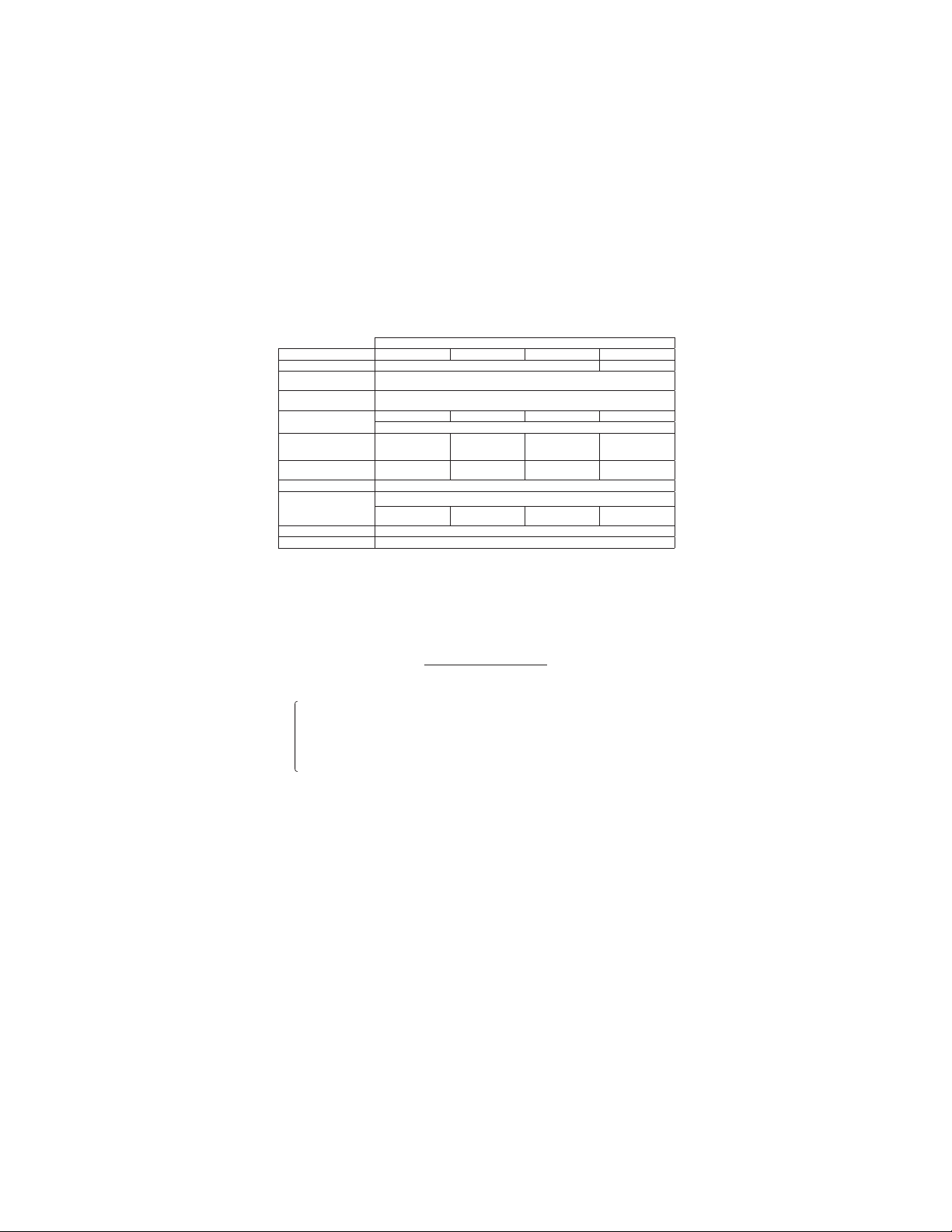
Measuring range and accuracy
<Insulation resistance range>
Nominal voltage 1000V 500V 250V 125V
Auto Range 0〜4/40/400/2000MΩ
Open circuit
voltage
Short circuit
current
Nominal test
current
st
1
effective
measurement
range
Center scale
range
Accuracy ±(2%rdg+6dgt)
nd
2
effective
measurement
range
Accuracy ±(5%rdg+6dgt)
Accuracy at 0 Within 6dgt
Nominal voltage 500V 250V 100V 50V
Auto Range 0〜4/40/400/2000MΩ 0〜4/40/200MΩ
Open circuit
voltage
Short circuit
current
Nominal test
current
st
1
effective
measurement
range
Center scale
range
Accuracy ±(2%rdg+6dgt)
nd
2
effective
measurement
range
Accuracy ±(5%rdg+6dgt)
Accuracy at 0 Within 6dgt
0.200〜
1000MΩ
2000MΩ
0.200〜
200.0MΩ
200.1〜
2000MΩ
Nominal test voltage 100%~120%
1MΩ 0.5MΩ 0.25MΩ 0.125MΩ
50MΩ 50MΩ 5MΩ 5MΩ
1001〜
Nominal test voltage 100%~120%
0.5MΩ 0.25MΩ 0.1MΩ 0.05MΩ
50MΩ 5MΩ 5MΩ 5MΩ
KEW3021A
Within 1.5mA
1mA 0%〜+20%
0.200〜
200.0MΩ
0.110〜0.199MΩ
200.1〜
2000MΩ
KEW3022A
Within 1.5mA
1mA 0%〜+20%
0.200〜
40.00MΩ
0.110〜0.199MΩ
40.01〜
2000MΩ
—
5
—
0.200〜
40.00MΩ
40.01〜
2000MΩ
0.200〜
20.00MΩ
20.01〜
200.0MΩ
0〜4/40/200MΩ
0.200〜
20.00MΩ
20.01〜
200.0MΩ
0.200〜
20.00MΩ
20.01〜
200.0MΩ
Find Quality Products Online at: sales@GlobalTestSupply.com
www.GlobalTestSupply.com
Page 8
Nominal voltage 1000V 500V 250V 100V
Auto Range 0〜4/40/400/2000MΩ
Open circuit
voltage
Short circuit
current
Nominal test
current
st
1
effective
measurement
range
Center scale
range
Accuracy ±(2%rdg+6dgt)
nd
2
effective
measurement
range
Accuracy ±(5%rdg+6dgt)
Accuracy at 0 Within 6dgt
0.200〜
1000MΩ
2000MΩ
Nominal test voltage 100%~120%
1MΩ 0.5MΩ 0.25MΩ 0.1MΩ
50MΩ 50MΩ 5MΩ 5MΩ
1001〜
KEW3023A
Within 1.5mA
1mA 0%〜+20%
0.200〜
200.0MΩ
0.110〜0.199MΩ
200.1〜
2000MΩ
0.200〜
40.00MΩ
40.01〜
2000MΩ
0〜4/40/200MΩ
0.200〜
20.00MΩ
20.01〜
200.0MΩ
<Operating uncertainty>
Operating uncertainty (B) is an error obtained under the nominal
operating conditions, and calculated with the intrinsic error (A),
which is an error of the instrument used, and the error (En) due to
variations. According to IEC61557, the maximum operating error
should be within +/-30%.
B =︱A︱+ 1.15 × √ ( E12 + E22 + E32 )
A : Intrinsic error(%)
B : Operating uncertainty(%)
E1: Variation due to changing the position(%)
E2: Variation due to changing the Supply voltage(%)
E3: Variation due to changing the temperature(%)
Nominal operating conditions
Ambient temperature : 0〜40℃
Relative humidity : 90% or less
Position : Horizontal〜±90゜
Battery voltage : within the battery effective range
—
6
—
Find Quality Products Online at: sales@GlobalTestSupply.com
www.GlobalTestSupply.com
Page 9

<Resistance range>
Auto-range 0〜40.00/ 400.0Ω
Open-circuit voltage(DC) 5V±20%
Short-circuit current DC200mA or more
Measuring range to keep
operating error/ tolerance
Outside of the measuring range to
keep operating error/ tolerance
<Voltage range>
Measured voltage 20 〜 600V
Accuracy ± (3%rdg+6dgt)
Accuracy at 0 Within 6dgt
<Number of measurement >
Possible number of measurement within the "BA
(Measure 5 sec., and take pause for 25 sec.)
Range Resistor for test
50V 0.05MΩ at least 1300 times
100V 0.
125V 0.
250V 0.
500V 0.
1000V
Continuity
Temperature & : 0℃〜 40℃ (RH: 90% or less)
humidity range (no condensation)
Storage temperature : -20℃〜 60℃ (RH: 75% or less)
& humidity range (no condensation)
Location for use : Altitude 2000m or less, Indoor use
Response time : Indicated value at each insulation resistance
Withstand voltage : A C5, 160 V(5 0/6 0Hz) fo r 5s . b et we en th e
Overload protection : The instrument operates properly after each of
1
125
25
5
1
range comes within accuracy within approx. 1
sec. after a resistance corresponding to the
mid-value and 0
the measuring terminals. (It may take
when measuring a capacitive load.)
electrical circuit and the enclosure.
the voltage shown in the table below is
0.2〜400Ω/ ±(2%rdg + 8dgt)
0〜0.19/Ω0.1Ω
TTERY.GOOD" range.
Possible number of
measurement
MΩ at least 1300 times
MΩ at least 1200 times
MΩ at least 1000 times
MΩ at least 1000 times
MΩ at least 400 times
1
Ω at least 1300 times
Ω
is suddenly applied across
applied.
time
—
7
—
Find Quality Products Online at: sales@GlobalTestSupply.com
www.GlobalTestSupply.com
Page 10
MODEL KEW3021A / 3023A KEW3022A
Continuity range
Insulation
resistance
AC voltage AC720V / 10sec. AC720V / 10sec.
Auto-ranging:
Range shifts to upper range : when a reading go over 4200
Range shifts to lower range : when a reading go to less than 320
Dimension : approx. 105(L)×158(W)×70(D)mm
Weight : approx. 600g (including batteries)
Power source : R6P or LR6 size AA x 6pcs
Nominal power : 2.7VA
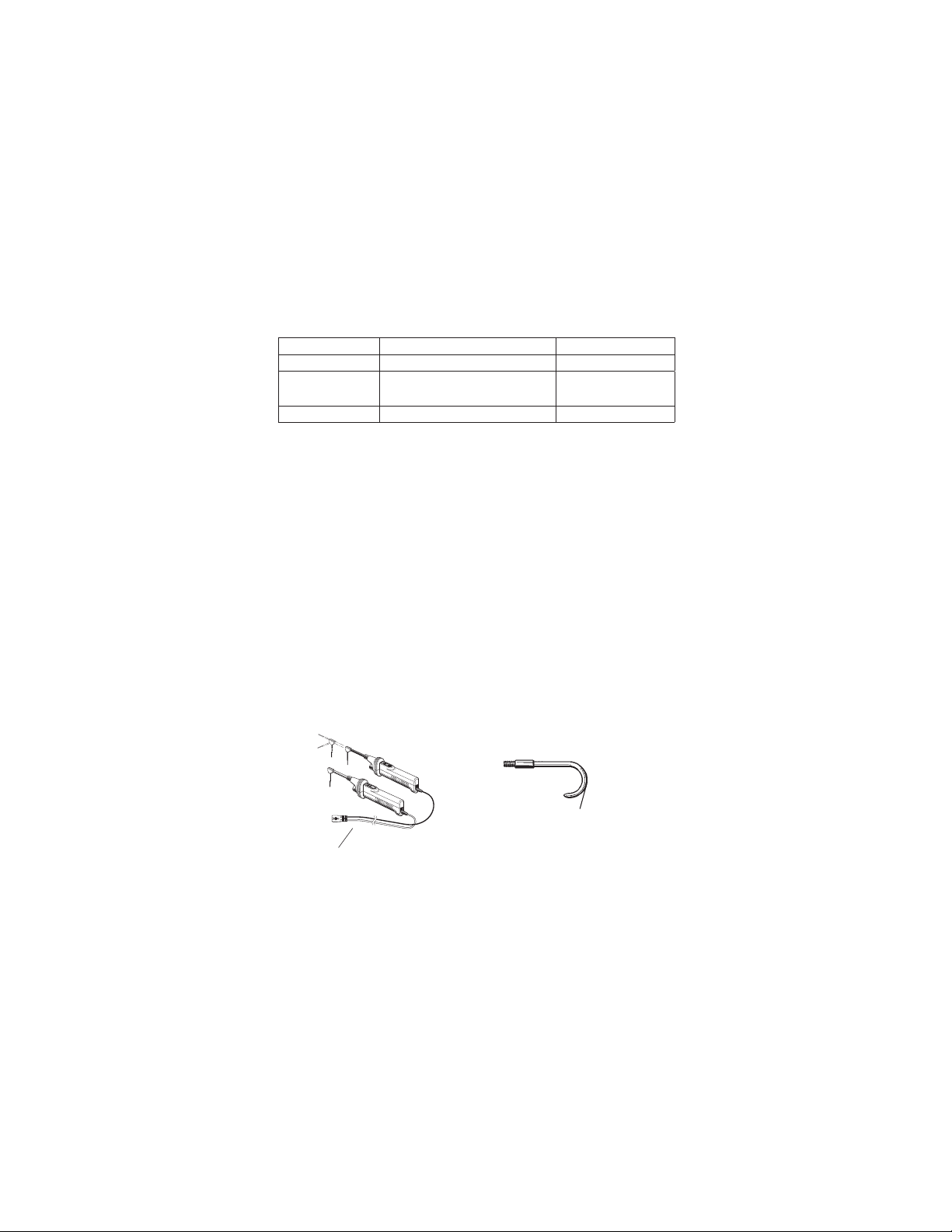
Accessories
MODEL7103A Test lead with remote control switch 1 set
MODEL7161A test bar 1 pce
MODEL7131B Safety alligator clip 1 pce
MODEL8017 Extension prod 1 pce
Neck strap 1 pce
Cord case 1 pce
R6P (SUM-3), size AA 6 pcs
Instruction manual 1 pce
Optional
MODEL7115 Extension probe
MODEL8016 Pickle type prod
AC 440V / 1min. AC 440V / 1min.
All ranges:AC1200V / 10sec.
AC600V / 10sec.
All ranges :
Pickle type prod
Extension probe
When the instrument and the test lead are combined and used together,
whichever lower category either of them belongs to will be applied.
Find Quality Products Online at: sales@GlobalTestSupply.com
www.GlobalTestSupply.com
Fig. 1
—
8
—
Page 11
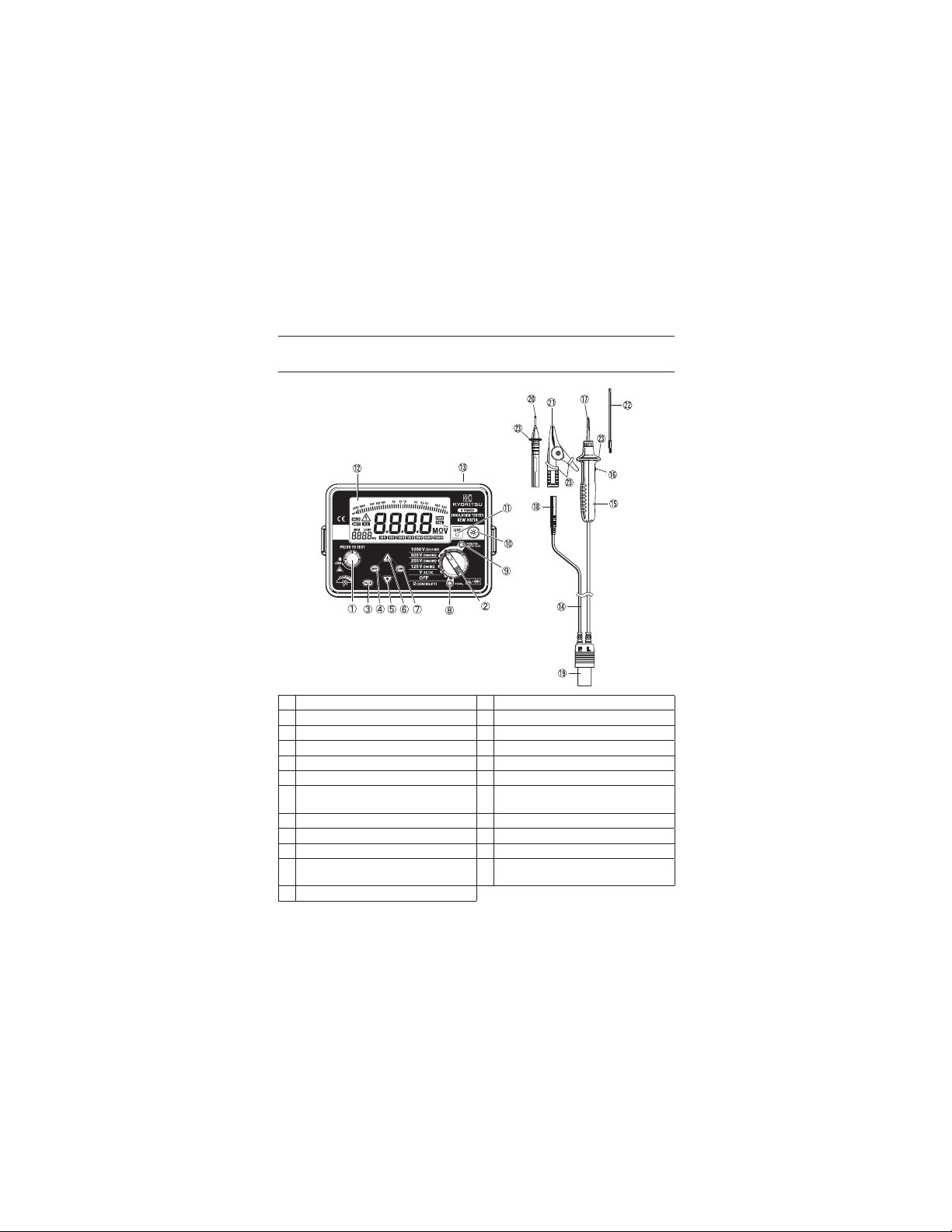
4.Instrument layout
Fig. 2 Instrument layout (KEW3021A)
Protective figerguard:
It is a part providing protection against electrical
shock and ensuring the minimum required air
and creepage distances.
① Test button ② Range selector switch
③ ENTER key ④ MEM key
⑤ DOWN key ⑥ UP key
⑦ Comp key ⑧ 0 Ω ADJ. key
⑨ Safety key ⑩ Backlight key
⑪ LIVE LED ⑫ Display
⑬ Probe socket ⑭ Test lead with remote control
⑮ Line probe ⑯ Remote control switch
⑰ Standard prod (MODEL8072) ⑱ Earth code
⑲ Probe connector ⑳ Test bar (MODEL7161A)
Safety alligator clip
㉑
(MODEL7131B)
Protective fingeguad
㉓
switch MODEL7103A
Extension prod
㉒
(MODEL8017)
—
9
—
Find Quality Products Online at: sales@GlobalTestSupply.com
www.GlobalTestSupply.com
Page 12

5.Preparation for measurement
5-1 Test lead connection
Insert the Probe connector into the Probe socket on the instrument
correctly as shown below.
Probe connector
Probe socket
5-2 Checks on Test lead and Fuse
(1) Set the Range selector switch on the instrument to theΩ
(CONTINUITY) position.
(2) Break in test lead or fuse is suspected if "OL" is displayed on the
LCD when shorting the LINE(red) and EARTH(black).
(3) Test lead or instrument itself may have troubles when "OL" is
displayed on the LCD after replacing the fuse. In this case, send
the instrument to your local KYORITSU distributor for repair.
DANGER
When the Test button or the Remote control switch is pressed
while the Range selector switch set to an insulation resistance
range, take care not to touch the tip of the Test probe where a high
voltage is present in order to avoid possible shock hazard.
Test lead and fuse must be inspected prior to measurement
according to Clause 5-2 indicated in this manual in order to avoid
possible electrical shock hazard. Voltage cannot be measured if a
break is present on the fuse.
#
—
10
—
Fig. 3
Find Quality Products Online at: sales@GlobalTestSupply.com
www.GlobalTestSupply.com
Page 13

6.Measurement
6-1 Voltage measurement (Mains disconnection check)
(1) Connect the Earth probe to the earth of the circuit under test and
Line probe to the other side. If the circuit is not earthed, connect
Earth probe to any appropriate conductor.
(2) Take the reading on the LCD without pressing the Test button or
Remote control switch. The mark " 〜 " is displayed when
measuring AC voltage. The mark " − (minus)" is displayed when
the LINE probe is connected to the negative side of the conductor
under test to measure DC voltage. "Lo" is displayed on the LCD
when the measured voltage is under 20V.
Fig. 4
DANGER
Test lead and fuse must be inspected prior to measurement
according to Clause 5-2 indicated in this manual in order to avoid
possible electrical shock hazard. Voltage cannot be measured if a
break is present on the fuse.
Never make measurement on a circuit in which the electrical
potential exceeds AC/DC600V in order to avoid possible shock
hazard. (Refer to "3.Specification, AC voltage measurement.")
When testing installation that has a large current capacity, such as
a power line, be sure to make measurement on the secondary side
of a circuit breaker in order to avoid personal injury.
Do not press the Test button or Remote control switch during
voltage measurement.
Never short live conductors with the tip of a probe to avoid
personal injury.
Do not make measurement with the Battery cover removed.
Keep your fingers and hands behind the protective fingerguard
during measurement.
6-2 Insulation resistance measurement
Before performing any insulation test, check the maximum voltage
that may be applied to the circuit under test.
#
—
11
—
Find Quality Products Online at: sales@GlobalTestSupply.com
www.GlobalTestSupply.com
Page 14

Note:
Some circuits have an unstable insulation resistance, which causes
the reading to vary during measurement.
The instrument may generate a high pitch tone during
measurement. This is not a failure.
If the circuit under test has a large capacitive load, it may take
some time before the final reading can be obtained.
On insulation resistance range, DC voltage is supplied through
earth and Line probes, with earth probe having positive polarity.
Earth probe should be connected to the earth conductor in the circuit
under test. Such connection is known to be more suitable
insulation tests since an insulation resistance value measured with
the positive side connected to earth is typically less than that taken
through the reversed connection.
DANGER
When the Test button or Remote control switch is pressed with the
Range selector switch set to an insulation resistance range
position, take care not to touch the tip of the test probe or the
circuit under test where a high voltage is present in order to avoid
possible shock hazard.
Do not make measurement with the Battery cover removed.
Ensure that the circuit under test is de-energized prior to any
insulation testing.
(1) Check the maximum voltage that may be applied to the circuit
under test. Set the Range selector switch to a desired insulation
resistance range. Keep the Safety key pressed down when
turning the Range selector switch to 500V and 1000V position.
(Only the 500V range is available on KEW3022A.) The message
"no" is displayed on the LCD when turning the Range selector
switch without pressing the Safety key.
Buzzer sounds when the Safety key is pressed down.
Keep the Safety key pressed down when switching 500V and 1000V
#
CAUTION
#
for
Fig. 5
—
12
—
Find Quality Products Online at: sales@GlobalTestSupply.com
www.GlobalTestSupply.com
Page 15

(2) Connect the Earth probe to the earth terminal of the circuit under
test. If the circuit is not earthed, connect the Earth probe to any
appropriate conductor.
(3) Connect the Line probe to the circuit under test and press the Test
button or Remote control switch.
(4) Take the reading on the LCD.
Fig. 6
Fig. 7
Principle of operation:
Resistance = Voltage/ Current
RX = V/ I
(5) Set the Range selector switch to the OFF position and disconnect
the test leads from the instrument after measurement.
<Auto discharge function>
This function allows electric charges stored in the capacitance of the
circuit under test to be automatically discharged after testing.
Set the Range selector switch to the OFF position or turn the Remote
control switch off with the test lead connected.
Discharge can be monitored by the LIVE LED and mark.
Fig. 8
—
13
—
Find Quality Products Online at: sales@GlobalTestSupply.com
www.GlobalTestSupply.com
Page 16

(6) Set the Range selector switch to the OFF position, and disconnect
the probes from the instrument.
DANGER
Never touch the circuit under test immediately after testing.
Capacitance stored in the circuit may cause electric shock.
Leave the test leads connected to the circuit until the LIVE LED
and LIVE circuit warning stop flickering.
6-3 Continuous measurement
For continuous measurement, a lock-down feature is incorporated on
the Test button. Pressing and turning clockwise locks the button in the
operating position, the button is released by turning it
counterclockwise.
While the Test button is locked down, a high voltage is present at
the tip of a probe. Attention should be paid to avoid possible shock
hazard.
6-4 Output voltage characteristics
This instrument conforms to IEC61557. This standard defines that the
nominal current shall be at least 1mA, and the lower limit of the
insulation resistance maintaining the nominal voltage at the
measurement terminal. (See the graph below.)
This value is calculated by dividing the nominal voltage by nominal
current. i.e., in case that the nominal voltage is 500V, the lower limit
of the insulation resistance is found as follows.
Divide 500V by 1mA equals 0.5MΩ.
That is, insulation resistance of 0.5MΩ or more is required to provide
the nominal voltage to the instrument.
Nominal voltage
Lower limit of insulation resistance
to supply nominal
current 1mA
50V 100V 125V 250V 500V 1000V
50k Ω
KEW3021A
#
DANGER
#
0.100M Ω 0.125M Ω 0.25MΩ
0.5M Ω 1M Ω
—
14
—
Find Quality Products Online at: sales@GlobalTestSupply.com
www.GlobalTestSupply.com
Page 17
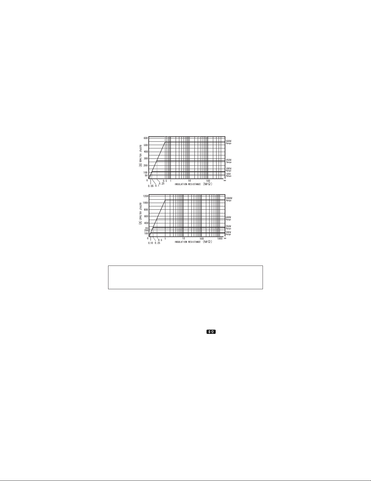
KEW3021A
KEW3022A
KEW3023A
Fig. 9
6-5 Measurement of resistance (Continuity check)
DANGER
Do not apply voltage to the resistance range. Always test the circuit
or equipment to ensure it is surely de-energized before
#
measurement.
Zero Ω ADJ. function
This is a function to null the resistance of the test lead or fuse in order
to display the resistance of the equipment under test only.
Setting:
(1) Set the Range selector switch to theΩ(Continuity) position.
(2) Short the test leads: LINE (red) and EARTH (black).
(3) Press the Zero Ω ADJ. key with the Test button locked or with the
Remote control switch pressed. Then
mark is lit up and a
value of 0.00 Ω is displayed on the LCD. This value is saved in
the memory of the instrument and won't be cleared after turning
off the instrument.
—
15
—
Find Quality Products Online at: sales@GlobalTestSupply.com
www.GlobalTestSupply.com
Page 18

Releasing:
(1) Set the Range selector switch to theΩ(Continuity) position.
(2) Open the test leads: LINE (red) and EARTH (black).
(3) Press the Zero Ω ADJ.
displayed on the LCD while the Test button is locked or the
Remote control switch is pressed down .
Measurement:
(1) Set the Range selector switch to the Ω (Continuity)position.
(2) Connect the test leads to the equipment under test, and press the
Test button or Remote control switch.
Principle of operation:
Resistance = Voltage/ Current
to release this function when "OL" is
key
RX= V / I
Note:
The zero Ω ADJ. function is available when the indicated value is
under 9 Ω .
A beak in Test lead or fuse is suspected when "OL" is displayed on
the LED even if LINE (red) and EARTH (black) are shorted.
Change the connection of LINE (red) and EARTH (black) when
measuring the voltage with the switched polarities.
The measurement result at the resistance function may be effected
by
the impedance or transient current in the operating circuit, which
is connected in parallel to the instrument.
6-6 Backlight function
To facilitate working in dimly lit situations, a
backlight function is provided which
illuminates the display. Press the backlight
to operate this function. The backlight
key
will light up for about 30 sec., and then turns
off automatically.
6-7 Auto-power-off
To prevent the instrument being left powered on and conserve battery
Fig. 10
Fig. 11
power, the instrument automatically turns off approx. 15 min. after the
last switch operation.
To turn on the instrument again, turn the Range selector switch to
OFF position once.
Then set it to the desired range.
—
16
—
Find Quality Products Online at: sales@GlobalTestSupply.com
www.GlobalTestSupply.com
Page 19

7.Functions keys
7-1 Comparator function
Set a reference resistance value at the insulation resistance range.
The measured value is compared to the pre-set reference value, and
the mark of
Settable reference value:
0.1/0.2/0.25/0.4/0.5/1/2/3/5/10/20/30/50/100/Any : Unit [MΩ]
The upper limit of
50/100/125 V : 0.000 to 199.9: Unit [MΩ]
250/500/1000 V : 0.000 to 999.9 : Unit [MΩ]
This function can be set at each range.
Setting procedure
(1) Set the range selector switch to OFF.
(2) While pressed down
any desired insulation resistance range.
In this case, there is no need to press the Safety Key to select
500V/1000V range.
(3) Press the UP or DOWN
press the
Select to sound the when the measured value exceeds the
pre-set value.
Select to sound the when the measured value is under the
pre-set value.
(4) The number displayed at the lower left on the LCD starts
flickering. Press the UP or DOWN
value, and press the
(5) The message and the set value are displayed on the LCD
once the setting completes.
(6) Press the key to release this function.
Setting for Any
(1) The decimal point displayed at the lower left on the LCD starts
flickering when "Any" is selected. Press the UP or DOWN
select the desired decimal position, and then press the
(2) The four-digit start flickering from the left. Press the UP or DOWN
key
e.g.: in case 0.5M
and set it to the desired value, and press the
or is displayed on the LCD and buzzer
"
Any" varies depending on output voltage.
key, turn the range selector switch to
key
to select or and then
key
key
.
to select the reference
Ω
key
is set.
.
key
key
to
key
.
.
7-2 Memory (save) function
Measured insulation resistance can be saved to the internal memory
up to 99 data.
Saving method:
(1) Measure the insulation resistance, and press the MEM key while
the message
Find Quality Products Online at: sales@GlobalTestSupply.com
www.GlobalTestSupply.com
Fig. 12. Change of sub-indication
is displayed on the LCD.Then a memory
—
17
—
Page 20

number displayed at the lower left flickers.Select any memory
number with the UP or DOWN key, and press the
(2) Then, the measurement result displayed at the middle on the LCD
flickers. Press the
the internal memory, and the memory number is increased by 1.
Press the
Recalling the memory data
(1) Set the Range selector switch to any desired Insulation resistance
range, and press the
(2) Press the UP or DOWN key to switch the memory number.The
measured voltage and value are displayed on the LCD.
Deleting all memory data
(1) To delete all memory, rotate the Range selector switch from OFF
to Ω (CONTINUITY) position with the
release the
(2) The message "clr" is displayed on the LCD. It flickers and buzzer
sounds when the
deletion is completed once "Ω" is displayed on the LCD.
Note:
The mark "---" is displayed on the LCD when no data is saved with
the selected memory No.
Resistance value is displayed on the LCD when data is saved with
the selected memory No.
Old data is overwritten with new when a new data is saved with the
same memory No.
key to delete the result.
key to save the result.It will be saved to
key.
key.
key is being pressed down again. The
key pressed down.Then
key.
8.Fuse & Battery replacement
DANGER
Never open the Battery cover during a measurement.Dispose the used
batteries according to the rules, which is defined by each community.
To avoid possible electric shock, remove test leads before opening
the Battery cover. After replacing batteries, be sure to tighten up the
screws for Battery cover.
#
WARNING
#
CAUTION
Do not mix new and old batteries.
Install batteries in correct polarity as marked inside the Battery
compartment.
8-1 Battery Replacement
(1) Disconnect the test probe from the instrument.
(2) Open the battery compartment cover by unscrewing the metal
captive screw to reveal battery compartment.
Find Quality Products Online at: sales@GlobalTestSupply.com
www.GlobalTestSupply.com
#
—
18
—
Page 21

(3) Always replace all six batteries with new ones at the same time.
(4) Screw the battery compartment lid back on before using the
instrument.
8-2 Fuse Replacement
(1) Disconnect the test probe from the
instrument.
(2) Open the battery compartment cover
by unscrewing the metal captive.
Screw to reveal battery compartment
and replace the fuse.
Fuse type: 500mA/600V(F) quick
acting ceramic fuse 6.35 x 32mm.
(3) Screw the battery compartment lid
back on before using the instrument.
BATTERY
Fig. 13
SCREW
FUSE
SPARE
FUSE
9.Notes on Housing case and accessories
9-1 Case lid
Case lid can be fit under the Housing case while making measurement.
(1) Unhook and open the Case lid.
(2) Turn it 180 degrees.
Put the Case lid under the Housing case.
(3) Hook it on to the Housing case.
Fig. 14
—
19
—
Find Quality Products Online at: sales@GlobalTestSupply.com
www.GlobalTestSupply.com
Page 22

9-2 Neck strap and Cord case
This instrument is equipped with a strap to suspend from the neck to
allow both hands to be used freely for easy and safe operation.
Fig. 15
9-3 Test prods and replacement
1. Types of Test prods
MODEL8072: Standard Test prod
Used for ordinary measurement.
(Attached to the Line probe at the time of purchase.)
MODEL8017: Extension probe
Used in difficult-to-reach situations.
MODEL8016: Pickle prod (Optional)
Used to hook the probe on a conductor.
2. How to replace Test prod
To remove the Test prod, turn the cap of LINE probe
counterclockwise. Insert the threaded end of another prod into the
hexagonal hole on the probe cap as shown. Then, turn the probe
cap clockwise to secure it on the body of the probe.
Female
Screw
Male Screw
Prod
Hexagonal Hole
Extension Prod
Pickel Prod
Fig. 16
9-4 Adaptors for the Earth cord and replacement
1. Adaptors
MODEL7131B: Safety alligator clip
Connected to the Earth terminal of the Earth terminal board.
MODEL7161A: Test bar
Connected to the earth side of the outlet.
—
20
—
Find Quality Products Online at: sales@GlobalTestSupply.com
www.GlobalTestSupply.com
Page 23
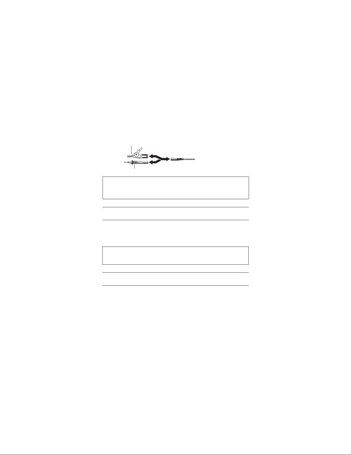
2. How to replace Adaptors
To remove the adaptors, pull them out. Then firmly attach the
adaptor as desired to the tip of the Earth cord.
Safety alligator clip
Test bar
DANGER
Disconnect the test leads from the instrument before replacing
the test prods of the Line probe or the adaptors of the Earth
cord in order to avoid a possible electric hazard.
#
Fig. 17
10.Cleaning of the instrument
Cleaning Meter cover
When cleaning the instrument, wipe it with a silicon cloth or soft
cloth to remove dust or dirt.
When it is hard to remove the dirt, wipe it with a cloth wet with
water and dry the instrument completely after cleaning.
CAUTION
Never use any solvent which may transmute plastics, for
example, organic solvent such as benzene, acetone, etc.
#
11.Servicing
If this tester should fail to operate correctly, return it to your
nearest distributors stating the exact nature of the fault.
Before returning the instrument, make sure that:
a) Operating instructions have been followed.
b) Test Leads have been inspected.
c) Fuse has been checked.
d) Battery has been checked.
e) The unit is returned with all accessory leads.
Remember, the more information written about the fault, the
quicker it will be serviced.
—
21
—
Find Quality Products Online at: sales@GlobalTestSupply.com
www.GlobalTestSupply.com
 Loading...