

Page 1

Instruction Manual
DC Milliamp Clamp Logger
KEW 2510
www.GlobalTestSupply.com
Page 2

Contents
1.Safety warnings
2
.
Features
3
.
Specifications
4
.
Instrument layout
5
.
Preparation
6
.
Getting started
6-1
6-2
7
.
Other functions
7-1
7-2
7-3
7-4
7-5
8
.
Communication function/ Application software
9
.
AC adapter power supply
9-1
9-2
10
.
Zero-adjustment
Measurement
Data Hold function
Auto-power-off function
Backlight & LED light
Analog output function
Memory function
How to use AC adapter
Specifications of AC adapter
Battery replacement
……………………………………………………
……………………………………………………………
………………………………………………………
……………………………………………………
…………………………………………………………
………………………………………………………
……………………………………………
………………………………………………
………………………………………………………
…………………………………………
……………………………………
……………………………………
……………………………………
…………………………………………
…………………………………………
…………………………………
……………………………………………
…………………
…………………………
1
4
4
6
6
7
7
7
8
8
8
9
9
9
10
11
11
11
12
www.GlobalTestSupply.com
Page 3

1.Safety warnings
measuring apparatus, and delivered in the best condition after
warnings and safety rules which have to be observed by the user to
ensure safe operation of the instrument and to maintain it in safe
Read through and understand the instructions contained in this
Keep the manual at hand to enable quick reference whenever
Understand and follow all the safety instructions contained in the
It is essential that the above instructions are adhered to. Failure to
follow the above instructions may cause injury, instrument damage
and/or damage to equipment under test. Kyoritsu is by no means
liable for any damage resulting from the instrument in contradiction to
refer to the related parts in the manual for safe operation of the
instrument. It is essential to read the instructions wherever the
is reserved for conditions and actions that are likely
is reserved for conditions and actions that can
is reserved for conditions and actions that can
○
This instrument has been designed, manufactured and tested
according to IEC
passing quality control tests. This instruction manual contains
condition. Therefore, read through these operating instructions before
starting to use the instrument.
●
manual before starting to use the instrument.
●
necessary.
●
The instrument is to be used only in its intended applications.
●
manual.
these cautionary notes.
○
The symbol # indicated on the instrument means that the user must
symbol appears in the manual.
#DANGER :
#WARNING:
#CAUTION:
61010
: Safety requirements for Electronic
#WARNING
to cause serious or fatal injury.
cause serious or fatal injury.
cause injury or instrument damage.
1
www.GlobalTestSupply.com
Page 4

Please refer to the following explanation of the symbols used on the
product may not be treated as household waste, but that it
Never make measurements on a circuit in which earth potentials of
Do not attempt to make measurements in the presence of
flammable gasses. Otherwise, the use of the instrument may cause
Never attempt to make any measurements if the clamp sensor and/
or the instrument has any structural abnormality, such as a crack,
The instrument should be used only in its intended applications or
instrument do not work, and instrument damage or serious personal
Keep your hands and fingers behind the safety barrier on clamp
Never attempt to make any measurements if any abnormal
conditions, such as a broken cover or exposed metal parts are
instrument. Return the instrument to your local KYORITSU distributor
Ensure that the Clamp sensor is disconnected from the object
under test, and that the instrument is powered off when opening the
medical electronic devices. Special care should be taken when using
instrument and in this manual.
User must refer to the explanations in the instruction manual.
#
Application around hazardous live conductors is NOT
permitted.
Crossed-out wheel bin symbol (according to WEEE
Directive:
must be collected and treated separately.
●
45
Vpk or higher exist.
●
sparking, which can lead to an explosion.
● Never attempt to use the instrument if its surface or your hand is wet.
●
Do not exceed the maximum allowable input of any measuring range.
●
Never open the battery compartment cover during a measurement.
●
or if the cover is not securely attached.
●
Do not measure AC currents.
●
conditions. Otherwise, safety functions equipped with the
injury may be caused.
●
sensor during a measurement.
●
present on the instrument and clamp sensor.
● Do not install substitute parts or make any modifications to the
for repair or re-calibration in case of suspected faulty operation.
●
Do not try to replace batteries if the surface of the instrument is wet.
●
battery compartment cover for battery replacement.
● Radio waves at Bluetooth communication may affect the operations of
Bluetooth communication in the areas where such devices are present.
2002/96
#DANGER
#WARNING
/EC) indicating that this electrical
2
www.GlobalTestSupply.com
Page 5

●
Do not expose the instrument to direct sunlight, high temperature,
This instrument is not water/ dust-proof. Do not use it in a dusty
Always power off the instrument after use. Remove batteries if the
Use a damp cloth with neutral detergent or water for cleaning the
To ensure safe operation of measuring instruments, IEC
categorized as O to CAT IV, and called measurement categories.
with greater momentary energy, so a measuring instrument designed
for CAT III environments can endure greater momentary energy than
Circuits which are not directly connected to the mains power
directly to the distribution panel, and feeders from the
and to the power meter and primary over-current protection
humidity or dew.
#CAUTION
●
environment or where it will get wet.
●
instrumentis to be stored and will not be in use for a long period.
●
instrument. Do not use abrasives or solvents.
○
Measurement Category
61010
establishes safety standards for various electrical environments,
Higher-numbered categories correspond to electrical environments
one designed for CAT II.
KEW
2510
O:
is CAT O rated. Do not use in CAT II, III or IV environments.
supply.
CATⅡ: Electrical circuits of equipment connected to an AC
electrical outlet by a power cord.
CATⅢ: Primary electrical circuits of the equipment connected
distribution panel to outlets.
CATⅣ: The circuit from the service drop to the service entrance,
device (distribution panel).
O: Device which is
not directly
connected to the
mains power supply
3
www.GlobalTestSupply.com
Page 6

2.Features
Temperature coefficient defined later in this manual and also zero
- should be taken into consideration if ambient temperature varies
●
Measure 4 to 20 mA instrumentation signal
●
Measure 0 to
●
LED light for illuminating the measurement spot
●
Auto-power-off function
●
Percentage (%) span
●
Analog output function to output the measured results to a recorder
or digital multi-meter
●
Data hold function
●
Memory function stores up to
●
Transfer data to PC via BluetoothⓇ
●
AC adapter supplied as a standard accessory
100
mA DC current without breaking the loop
192000
records
3.Specifications
●
Measuring range and accuracy (23ºC±5º
(1)DC current (auto-range)
Range Display range
20mA0.00~±21.49mA0.00~±21.49mA±0.2%rdg±5
100mA±21.0~±
※
Cautions for a long period of measurement or recording:
・
A b o u t 10 min of warm up is required right after powering on the
instrument.
・
point fluctuation – about 20 counts with a 10º
during a recording.
(2)Analog output function
Output DC voltage (10mV/mA) corresponding to a reading.
Range Display range Output voltage Accuracy
20
mA0.00~±21.49mA0.0~±
100mA±21.0~±
※
1300
mV is output when the display shows ”OL”. (-
See clause 6 for explanations on OL display.
※
Output impedance : approx. 5k
126.0mA±21.0~±
Guaranteed accuracy
126.0mA±
www.GlobalTestSupply.com
210~±126 0
Ω
C, RH 75% or less)
Accuracy Condition
120.0mA±1.0%rdg±5
C rise in temperature
214.9
4
Accuracy specified at clause
mV
3 (1
) plus (±0.5
Accuracy specified at clause
mV
3 (1
) plus (±3
1300
After Zero-
dgt
adjustment
described at
dgt
clause 6-1.
mV)
mV)
mV for“-OL”.)
Page 7

●
switch operation. This function is disabled when a
cord is being connected to the OUTPUT terminal
Applicable standards
Measurement CAT O (Other), Pollution degree
IEC
IEC
IEC
EN
●
Display Liquid crystal display
(See also
●
Refresh rate Approx. once/ 0.6 second
●
Sampling rate
(Averaging data in about
●
Location for use In-door use, altitude
●
Operating temperature
& humidity
●
Storage temperature
& humidity
●
Power source Size AA battery x 4 pcs
(Alkaline LR
External supply (AC adapter MODEL
●
Battery life
IEC
61010-1
61010-2-032
613 2 6-1
60529
50581
(EMC)
IP
40
RoHS Directive
“4. Instrument layout”.)
Approx. 4ms
0.6
sec.)
2000
-10 to +50º
C RH85% or less (no condensation)
m or less
When using AC adapter:
0
to +40º
-20 to +60º
C RH85% or less (no condensation)
C RH85% or less (no condensation)
6
is recommended.)
Approx. 50 hours continuous with alkaline batteries
8320
2
)
(with Backlight, LED light and BluetoothⓇfeature OFF)
●
Auto-power-off
Power off function operates in 10 min after the last
and memory function to record results is activated.
●
Temperature
coefficient (above 28º
●
Withstand voltage
0.1
x specified accuracy/ ºC
C or below 18º
2210
V AC for 5 sec
C)
(between electrical circuit and enclosure)
●
Insulation resistance 100MΩ
or more/
1000
V
(between electrical circuit and enclosure)
●
Rated voltage
●
Conductor size Max. Ф6
●
Dimension
●
Weight Approx.
●
Accessory Soft case MODEL
Size AA Alkaline battery LR
Instruction manual
AC adapter MODEL
CD-ROM (KEW Windows for
Software installation manual
●
Optional accessory
42
Vpk (circuit – ground)
mm
111
(L) x 61(W) x 46(D)mm
310
g (including batteries)
9096
・・・・・・・・・・・・・・・・・1 pce
・・・・・・・・・・・・・・・・・・・・・・・1 pce
8320
Analog output cord MODEL
6
・・・・・・・・・・・4 pcs
・・・・・・・・・・・・・・・1 pce
2510)・・・・1 pce
・・・・・・・・・・・・1 pce
7256
5
www.GlobalTestSupply.com
Page 8
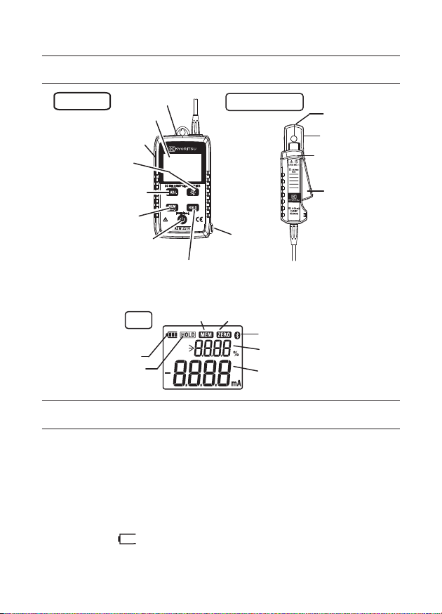
4.Instrument layout
Power on the instrument, and then check smooth opening and
When operating the instrument with battery, always check the
battery voltage, without connecting the AC adapter, before
regardless of battery status while the AC adapter is connected to
Press Power button and get the instrument started. If empty battery
appears in the LCD, replace the batteries with new
Ensure that the Data hold function is not in active status.
LED light
Main unit
External supply
connection terminal
Light button
Zero adjustment
(0 ADJ.) button
Memory
(MEM) button
Barrier: It is a part providing protection against electrical shock and
ensuring the minimum required air and creepage distances.
Battery mark
Hold mark
LCD
Power button
Data hold button
LCD
Memory mark
Clamp sensor
Analog output
terminal
Zero adj. mark
Bluetooth®mark
Sub display
Main display
Transformer
jaws
Polarity mark
Barrier
Trigger
5.Preparation
(1)
closing of clamp sensor.
(2)
starting to use the instrument. Battery mark doesn’t appea r
the instrument.
indicator
“ ”
ones according to“9
(3)
. Battery replacement”in this manual.
6
www.GlobalTestSupply.com
Page 9

6.Getting started
Dirty clamp sensor may cause false reading. Confirm that clamp
When performing zero adjustment in order to minimize the influence
of electromagnetic waves, bring a clamp sensor close to the
results may not be obtained. Please open and close the sensor
With the transformer jaws closed and without clamping them onto a
Press the trigger to open the transformer jaws and clamp them onto a
●
Do not clamp onto an un-insulated conductor.
●
Always use analog output cord MODEL
7256
, specially designed to
this instrument, when using analog output function.
#DANGER
#WARNING
●
Keep your fingers and hands behind the barrier during a
measurement.
#CAUTION
●
sensors are clean before making a measurement.
●
conductor under test.
●
Take sufficient care not to apply shock, vibration or excessive force
whenopening and closing the clamp sensor. Otherwise, accurate
lightly.
6−1Zero-adjustment
Perform zero adjustment prior to starting a measurement.
conductor, press the Zero ADJ. button.
Then the Zero adjustment mark“ ”is shown on the LCD for
about
1
・
・
sec.
Zero ADJ. button is disabled while;
the LCD showing“OL”, or
recording results with memory function.
6−2Measurement
conductor under test and take the
reading shown in main display area.
(See the figure below.)
• When a current flows in the same
direction as indicated by the arrow
mark on the jaws, the polarity of
the reading is positive and vice
versa.
correct
wrong
7
www.GlobalTestSupply.com
Page 10

※
mA, bars (---) are displayed instead of
the Data hold button once to freeze the reading. The reading will be
held regardless of subsequent variation in input. The Data hold mark“
"is indicated on the display while the instrument is in the Data
operation. This function is disabled if the cord is being connected to
the analog output terminal or while recording measured data with
powering on the instrument. To restore this function, power off once
% (Span) display
The sub display shows percentage value as the basis of 4mA is 0% and
20
mA is
100
%. (at 20mA range only)
The table at the right shows the
relationship between %(Span)
values and measured values (mA).
Measured
values (mA
-20.
The percentage value is
calculated based on the
following formula, assuming the
measured value as X.
Percentage = (
※
Over-limit indication
When a measured value exceeds the max display range (
" O L" o r “-OL” (for negative values) is indicated on the display.
When the range reaches to
percentage values.
│X│
- 4.00)×6.25
100
12
20
100
Percentage
display (%)
)
00 100.0
0
.
00
2
.
00
4
.
00 0.0
.
00 50.0
.
00 100.0
.
0
-25.
-12.
---
126.0
0
5
mA),
7.Other functions
7−1DataHoldfunction
This is a function to freeze the measured value on the display. Press
Hold mode. To exit Data Hold mode, press the Data hold button again.
7−2Auto-power-offfunction
The instrument automatically powers off about 10 min after the last
memory function.
Todisablethisfunction:
Hold down the Data hold button while powering on the instrument.
The LCD shows “P. o FF” for about 1 sec immediately after
and power on again.
8
www.GlobalTestSupply.com
Page 11
7−3Backlight&LEDlight
Press the Light button to turn on/ off the LED light and LCD
backlight. These lights automatically turn off after two minutes. To
disable the automatic light timeout, hold down the Light button while
sec immediately after powering on the instrument. To restore
DC voltage signal corresponding to the measured result is output
recorder or a digital multi-meter connected to the instrument by using
the main display and number of stored record is on the sub display
powering on the instrument. The LCD shows “L.oFF” for about 1
automatic light timeout, power off once and power on again.
7−4Analogoutputfunction
from the analog output terminal. (10mV/mA) It can be checked on a
MODEL
7256
※
When connecting the
analog output cord to
output cord.
Digital multi-meter
or recorder
the instrument, the subdisplay shows “OUT”
for 1 sec.
Analog output cord
MODEL7256
7−5Memoryfunction
Store measured values in the internal memory of KEW
2510
. Hold
down the Memory button 1 sec or longer to start recording. Another
long press will stop the recording. The mark keeps blinking on
the LCD duringa recording. Power button doesn’t work in this period.
※
Max number of records :
※
Recording interval : 1/5/10/30/60 sec.
Use the special application software to
change the setting of recording
interval. Default setting is 60 sec.
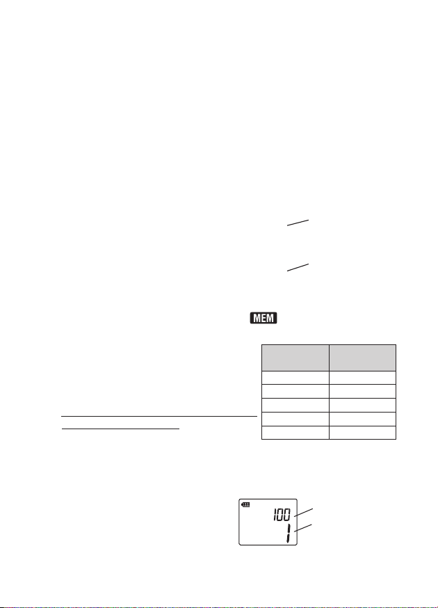
Checking recording interval and
number of stored results :
Press the Memory button to show the
192000
Recording
interval
1
sec
5
sec
10
sec
30
sec
60
sec
Max recording
period
53
hours
11
days
22
days
66
days
133
days
currently selected recording interval on
for 1 sec.
e.g.
100
results stored with
recording interval of 1 sec.:
Number of records
Recording interval
9
www.GlobalTestSupply.com
Page 12

※
Recording stops when number of records reaches to the upper limit
. Recorded data is secured even when a recording is
interrupted by the exhausted batteries or when the instrument is
When starting a new recording, the previous recorded data will be
leave the instrument for the warm-up period of several tens of
readings will vary when the ambient temperature changes. In this
: For the supported OS, please check the version
When number of records exceeds
give numerical indication but just shows“>
※
A short press, 1 sec or less, displays the pre-set recording interval
and number of records. Do not press the button 1 sec or longer for
confirmation, otherwise recording will start/ end.
※
of
192000
powered off for battery replacement.
※
deleted. Use the special application software and download the
recorded data to your PC.
※
When making measurements for a long period of time :
・
minutes after powering it on, and then start a recording.
・
case, the temperature coefficients specified at clause 3 and
fluctuations at zero (about 20 counts fluctuate when temperature
changes by 10º
8.
●
Interface
Communication method: Bluetooth® Ver2.1+EDR Class
Compliant profile : SPP
●
System requirements
OS (Operation System)
Memory
Display
HDD
.NET Framework : 3.5 or later
●
Trademark
・
WindowsⓇis a registered trademark of Microsoft in the United States.
・
BluetoothⓇis a registered trademark of Bluetooth SIG.
C) should be taken into consideration.
Communication function/ Application software
label on the CD case or visit our homepage.
: 1Gbyte or more
:
1024
: 1Gbyte or more (including Framework)
www.GlobalTestSupply.com
x
768
10
10000
dots,
, the sub display doesn’t
9999”.
2
65536
colors or more
Page 13

●
instrument configuration via PC. Refer to the supplied software
installation manual and install the application in your PC. For the
Confirm the rated power supply of the outlet is not exceeding the
Do not put an object on the adapter or cord. Keep them away from
When disconnecting the adapter from an outlet, do so by removing
. Remove the cover for external supply, located on the side face of
Use of AC adapter is recommended for long time recording. It is also
Application software (KEW Windows for
This special application enables data download, analysis and
details, see the manual for
the icon to be created in the desktop after installation.
BluetoothⓇmark“ ”displayed on the instrument indicates the
instrument and the installed application software have been
connected.
“
2510
)
KEW Windows for
2510
”
by clicking
9.AC adapter power supply
●
Use only MODEL
●
rating of the AC adapter.
●
Unplug the adapter if it will not be used for a long period.
●
a heating object.
●
the plug not by pulling the cord.
9−1HowtouseACadapter
1
the instrument, and connect the AC adapter.
2
. Connect the plug of the AC adapter to an outlet.
9−2SpecificationsofACadapter
●
Rated power supply, frequency :
●
Rated output voltage : 9 V DC
●
Rated output current : 1.66A (max)
recommended to operate the instrument on AC adapter power with
batteries installed for backup purpose. The instrument switches
power source to batteries in an event of power outage.
※
Confirm battery level without connecting the AC adapter
beforehand. Battery indicator doesn’t appear while AC adapter is
being connected to the instrument.
8320
#WARNING
AC adapter with this instrument.
100-240
11
www.GlobalTestSupply.com
V AC, 47-63Hz
Page 14

10.Battery replacement
Ensure that the clamp sensor is disconnected from the object under
test, and that the instrument is powered off when opening the
Disconnect the AC adapter and analog output cord from the
displayed on the LCD. The LCD does not show anything, even the
batteries, in correct polarity. The use of alkaline batteries (LR6) is
#WARNING
●
battery compartment cover for battery replacement.
●
instrument.
#CAUTION
●
Do not mix new and old batteries or mix different types of batteries.
●
Install batteries in correct polarity as marked inside.
Replace batteries with new ones when the empty battery mark“ ”is
empty battery mark, when batteries are completely exhausted.
[Howtoreplacebatteries]
(1)Power off the instrument.
(2) Loosen two screws at the backside of the instrument and remove the
battery compartment cover.
(3) Remove all the old batteries and install new ones, four size AA
recommended.
(4)Reattach the cover and tighten the screws.
Battery compartment
cover
Screw
12
www.GlobalTestSupply.com
Screw
 Loading...