

Page 1

I(IPERATING
INSTRUCTI(IN
I
ROTARY
SCALE
SNAP-ON
DC VOLT-OHM-AMMETER
IITIU
SNRP
7
Our
continuing
research
has
made
it
possible
for
the instrument
to be more
free trom
the
residual
magnetism
which
is
rncidental
to
this type
of instrument
designed
to measure
drrect
current
only.
our Kew
snap-7
embodies
the finest
of
our
engineering
experience
and
knowledge
in
its
compact
form"
An
ideal
instrument
that can
meet varying
needs in
the
automobile
industry
such
as servicing
at
gas
stations
or
repair
shops, checking
batteries
and
regulators,
and also diagnosing
erectricar
systems.
Also,
very
useful
for
servicing
and
ma;ntenance
of various
types
of
electrolystic
equipment in
the
electro-chemicat
lndustry.
For
its
funct;onal
design
and unique
engineering
concept
our Kew
snap-7 wiil
prove
to
be a fascinating
service
instrument
to tlrose who
work
with
variclus
facilities
related
to the
telsphqps
switchboards,
electronic
computors,
electrolystic
refinery
and high voltage
electrostatic
power
appl icat ion.
O
Provided
with
a
warning
lanrp
that
will
autornatically
inclicate
the naed
for
battery
replacement
when
the instrument
is
in use.
O
Powered
by only
one
Eveready
216
(006p)
rype
gV
battery
which
is readity
availaole.
o
integrated
circuit
boar<i
used
ensures
the steady
performarrce
of the instrum€nt.
O
Other
features
include
the
pointer
lock
system.
voltage
tesrleads
ar.rd ohmprobe
with
threadsd
plugs.
ohmprobe
is
also supplied
with
a fuse
to
protect
the meter lrom
burnout.
Like
other Kew
snap
series
our Kew
snap-7
is
packed
with
a number
of
such
outstanding
features.
Page 2

Page 3
I
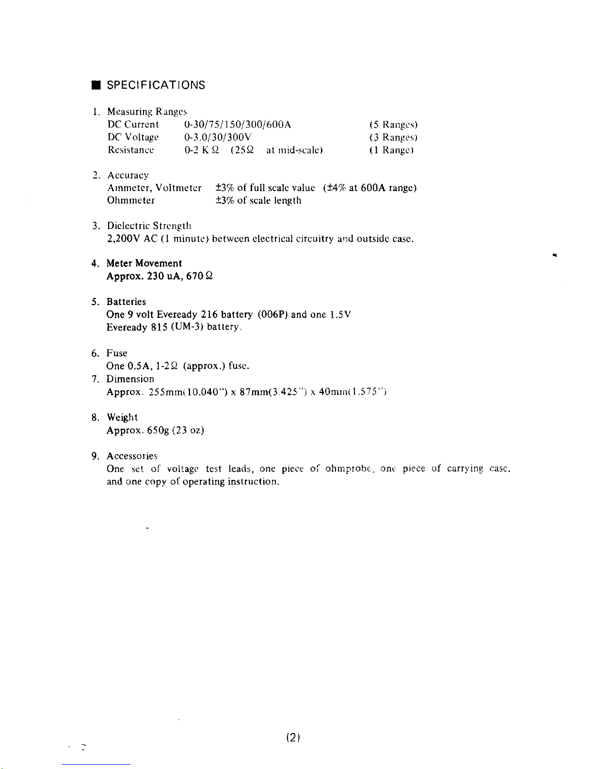
SPECIFICATIONS
l.
Measuring Range s
DC
Current 0-10/75/ I 50/300/600A
(5
Rangcs)
DC Voltage
0-3.0/30i
300V
(3
Ranges)
Resistancc
0-2 K Q
(25Q
at nrid--scalc)
(l
Rangc)
2. Accuracy
Arnmeter,
Voltmeter
13%
of full
scalc
value
(!4%
at
600,4'
rangc)
Ohmmeter
+l'le
of
scale length
3.
Dielectric
Strength
2,200V
AC
(l
minutc) between electrical oircuitry aud outside casc.
4. Meter
Movement
Approx. 230 uA,
670
Q
5. Batteries
One
9
volt Eveready 216
battery
(006P)
and one
l.5V
Eveready
815
(UM-3)
battery.
6.
Fuse
One 0.5A, l-20
(approx.)
fuse.
7.
Dimension
Approx"
255mrn(10.040") x 87mm(3.425
')
x 40mtn(I.575"i
8.
Weight
Approx.
650g
i23
oz)
9.
Accessories
One se1 oi
voltagr
test leads,
cne
piece oi
ohrnprobc,
onc
piece
cf carrying
case.
and
one
copy of operating instruction.
t2l
Page 4
NOTE: I()
F,NSI.,.RIJ
T}IE
N{AXI]\{LiN'I tsA.I.].F:RY
1,IFI],
BE SURE
TO
SWITC}{
OI..F
l'lilr l-O\\'I'lR I'.XCI:-P'|
WIILN MIIASLIRING CLRRtNT.
\IOLl',\(llr
:'IrS'I
I.FAilS
AND OL{NtPR()Ittr:
\1US'f IIE LIll-'T
RFIN{OVEI)
i'l{.OU
iiii lNSl RLirl!i:.N'i
\\}ll:.}i NO'l RI'l()tilRtD
IiOR
!{EASLiRFINIt'INTS
I
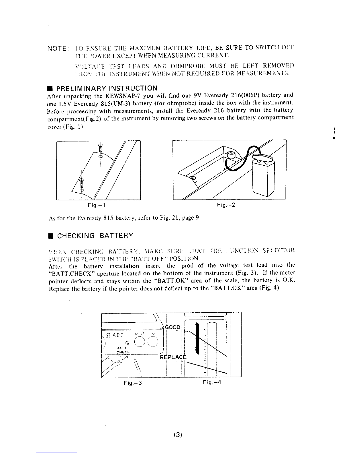
PRELIMINARY
INSTRUCTION
After
unpacking
the KEWSNAP-7
you
will find one 9v
llveready
216(006P)
battery
and
one l.-5V
L,veready 815(UM-3)
battery
(for
ohmprobe) inside
the box
with the instrument.
Ilelore
proceeding
with measurements,
install
the
Eveready 216
battery
into
the battery
contpartment(Fig.2)
of thc
instrument
by
rernoving two
screws
on the battery
compartment
covcr
(Fie.
l).
Fig.-
1
Fig.-2
As
for the.[veready
815
battery,
refer to
Fig.
21,
page
9.
T
CHECKING
BATTERY
\\ll!-\
('1lF-CKIN(;
BAf
lL,RY.
I,lAKt'l SURt:
ll{Af
-flita
I i-jN{'l
I(lN 3l-.ill(l'f()R
-c'"VIl(
ll
lS
FLA{.'ID 1N
"flih
"UA'f'I'.OI;F"'
POSIl'lON.
Aftrrr the
battery
installation
insert the
prod of the
voltage.
test lcad
into the
"BATT.CHECK"
aperture
located on the
bottom
of the instrument
(Fig.
3).
lf
the mctcr
pointer
cleflects
and stays
within the
"BATT.OK"
area
of thc
scale, the
battcry
is o.K.
Rcplace
the battery
if the
pointer
does
not deflect
up
to
thc
"BATT.OK"
area
(Fig.
4).
F is.-3
(3)
Fin
-A
Page 5

I
t.
MEASURING
DC CURRENT
(All
current
scales are
printed
in black)
Turn zero
adjust screw to
position
the meter
pointer
over the zero
on
the scale
(Fig.
5).
2.
PLACT]
TIIE IJUNCTION S}.]LF]('TOR
SWITC}I
IN
THE "+''
POSITJON
(POWI..R
IS
ON).
TURN THE
RANGF] SELECTOR
SWII'CII
KNOB UNTIL 600A
SCALE
APPEARS.
TTIEN
'TURN
"A
CAL'' SWITCII
KNOB
ON THE
RIct{T
SIDE
O}r TtlE
INSTRUMT'lN't
(F'ig.
6)
TO ZT.,RO
TI{I.i
MT.]TI]R RTAI)IN(;.
TURN
THE
RANGT1 SI;LI]CTOR
SWITCTI
KNOB trNTlL 300v
(3.0v,
30v
oR 30A)
SCALE.
APPF.ARS.
lF TIIII
MLTITR
POINIER
IS OI:I:
TTIE ZERO
POSITION
SET
ft TO
ZI'RO BY
TURNING
TIII.]
"BALANCE''
KNOts
LOCATI.]D
ON T}IE
TJPPI:R SEC'TION
Ol.' THE ITRONT CASE
(Fig.
7).
A,(;AIN
SI.]T fI{F- SCALT,]
TO THI., 600A
RANGI,
ANI)
MAKH TTIL ZIIRO
ADJIJS]'
lv{ENI
WIftl 1.}llr
"A
('AL"
Swll'(l}l
KNOll"
I{EPI]AI"T}IF]
AI]OV
h] PROCEDU
RI:S TWICII
OR l'llRF.tl
TIN'lf:lS
S0 1'ltA'l'Tt{ERll
IUAY
NOT
OCCUR
TFII] SIIIF"T
O}.'I-TIE
PoIN-TIR
Zt.]RO
POSIl'ION.
-
o
t
tu
N
Fig.-5
F is.-6
F i9.-7
(4)
Page 6

4.
Set
the dial drum scale to a
desired ampere range and make sure that
the meter is
zeroed.
Press the
jaw
trigger to open the transfornrer
jaws.
When the conductor
tr: be measured is enclosed
within the
jaws,
the ampere
reading
may be
taken.
If the
pointer
is
deflected in
the
opposite direction
place
the
function
selector srvitch
in the
"-" position.
When
the
current
to be
measured is
of
an
unknown order
select
the highest
600A
range first
and then the most
appropriate
range.
Fig.
8 shows
the current flowing in the
'positive
(*)
direction and Fig.
9
in the
negative
(-)
direction.
NEGATIVE
DIRECTION
READING
5.
When
a DC current is measured, a
hysteresis effect may be introduced into the
transformer core. To
remove
this completely
it is necessary to enclose a large AC
current carrying conductor
within the
jaws.
It is also
possible
to minimize
the
hysteresis
effect
by operating the
jaw
trigger a
few trmes to open and close thc
transformer
jaws.
On the
30A
range this hysteresis effect is the
largest with 4 to
57o error in the meter
indication. A highest degree
of
accuracy
can
be
obtained when
the current being measured is a
perfect
DC currcnt.
5.
Pointer
lock is
used
to
facilitate thc mcasute-
ment
of conductors in areas
of
poor
accessi-
bility or inadequate illumination.
In such
cases, when the reading is
registering on the
scale. simply
slide the
pointer
lock button to
the
left, to lock the
pointer
in
place,
and the
instrument'may be
removed to an area
where
it may
be read easily, before
releasing the
pointer
(Fig.
l0).
I
Fig.-8
I
-Er9m.-
v'f-
F
is.-9
F ig.-
l0
(5)
Page 7

As described
on
page
3, make
sure that the
voltage
test
leads and ohmprobe
arc
removed from
the instrument
during
the current
measurements.
If the ohmprobe
is lell
plugged
in, the
accuracy of
the current
measurement
may be affected
anrl
in addition
the fuse
located
in the ohmprobe
may be burned out
so that
the
reslstance
measurement
may not
be made,
SNAP AROL)ND
ONll
CONDUCTOR
ONI.Y
(I:ig.
ll). TII[, I\tE'ftjR
WILL
NOT
DIT,FLE('T
IF TWO
CONDUCTORS
ARE
I.NCLOSID WtTI{tN'I}iE.!AWS
(Fig.
12).
DURING
CURRENT MEASUREMENTS "REPLACE
BAT]'L]RY''
LAMP
ON THI:
SCALE PLA'tl1
LIGHTS tlP
INDICATING
THAT
THE BATTIiRY
IS WEAK.
Battery replacement
may be made
easily
by removing
the two
screws on the
battcry
compartment
cover
(Fig.
1)
as illustrated
on
page
3.
Immediately
after
completing
current
measurements, place
the lunction
selector
switch in the
"BATT.OFF"
position.
THE
FUNCTION
SELECTOR
SWITCH
SHOUI-D
ALSO
BE
LEI.'T ON THIS
POSITION
WHEN
THE
INSTRUMENT
IS
NOT
lN USI:.
F
ig.-
12
(6)
Page 8

I
MEASURING
DC
VOLTAGE
(All
voltagc scales
are
printed
in
red)
l.
BEIiORI:
VOLfA(;i:
1\'lllAStJRIrMEN'IS CHLIC'K
1'O Bl. SURI-
IHAT
TIILI
POINTIIR
lS
Rl,(;lsl taRING
IIXA('T'LY
ZERO.
ADJtts
tN'tFlNT,
Wt{tN
NFICDSSARY'
MAY BI''
\'1,\l)t' BY NIEANS
OIII lllr ZFIRO
ADJUST SCRI-IW,
I-OCIATED
ADJACITN'I
l'O
TIll:
POINTIiR L,OCK
(Fig.
5).
.t
J.
TIAKL, CLRTAIN
TIIAT
T[IF]
FUNCTION STiLUC]TOR
PfJSI'TION.
TIII.]
N'IIi'I'IJR
WII.,t- NOT DEFLECT
WTIEN
P(Jsll'loN.
Thread
the
red voltage test
lead into
the "+V"
receptacle
located
on the
bottom
of the
instrument
and
black test
lead into
the "V.
Q "
receptacle
clockwise
until they
lock in securely.
(Fie.13).
Connect
the
rcd test lead
(connecting
end
may
be either
prod
or clip) to
the
positive
(+)
side
of thc
circuit under
test and
the black tcst
lead
(connecting
end
either
prod
or clip)
to the
negative
(-)
side.
For
example,
connect
the
clip
of the test lead
to
one
side
of the circuit
under test
and,
holding the instrument
in
hand,
touch
the
prod
of other test
lead to
other sidc
as
shown in
Fig. 14. If
the
pointer
indicatcs
in excess
of
the
ratcd 300V
remove
the tcst
lead from the
circuit immediately.
6.
The
voltage test leads are constructed
as shown
in
Fig.
15.
The
prod
can
be removed by squeezing
the
rubber insulator.
swt]'crt
ls IN
]'IIti
"V.
!l
'
THH SWITCII
IS I'N
OI'III]R
F is.-
13
F ig.-
14
PROD
4. Turn the
range selector
switch
knob until
the 300V
range appears
in the
window.
Note that the
three
volt ranges are
provided
in order
of
3.0V,
30V
and 300V
full
scale.
If
the voltage
under test is
of an
unknown
order
procecd with the
voltagc
measurement
from the
highest
300V
range.
THREADEO
PLUG
,l
=<-_')--_1
-
\-
--\
INSULA
F is,
F<Dq_
TOR
,-15
(71
CUP
Page 9

I
MEASURING RESISTANCE
(Ohm
scale is
printed
in black)
INSFRT
{Jill\{PR{irJl.
l}i'iai lN51'R.1,1!,!1,.N'l:
{}Nl.
y
1il.lf
li \It.ASURINC
ItLStSi:1.NC!
l. liltrORl:. l\{AKING I{ilsISTAl\CL
il{}lASURF.lvll-.Nl.S, BI:
Sl,rRL. l HA'I
'f
Ht
ClRCL,l I
I,Nill--R
TIIST
IS
"DFIAD""'THAT
tS.'iiltrRE IS N0
vOl.'f;\GI
C(;NNLtCfL-D.
IN
CASL, OF ACCIDLNTAL
CONTA(l'I
OIj
'l-FiL
DtilvtPR{J}l[.
T{) \
"LIVE"
CIRCUIT ACCtiRATt', MI'IASUREMENTS
CANNOI IJE
\iADI1.
ALTTIOt'(li{
lllt
FtrSE
CON'IAINED lir- TIIE,
OI{I\{PROBI'. WILL PROTITCT TIIE
INSTRU\1[.N1'
F8.OM
BURNOtIT.
2.
Insert
one of
the
voltage
test leads into
the "V. Q
" receptacle
located on the
bottom
of
the instrument,
push
firmly
in and turn clockwise
to
lock
(Fig.
16). Insert the
ohmprobe
into the
"
Q
" receptacle on
the
right
side
of the instrument,
push
ilrmly
in and turn
clockwisc to lock
(Fig.
17).
F
ig.- 16
Maks
sure that the
pointer
is
on
the
"
€
"
mark of thc scale.
lf not, set the
pointer
to
the
"
@
",
using the zcro adjust screw
(Fig.
5).
When
making this adjustment,
do not short
the test leads
(l.ig.
1
8).
F is.-
17
-
o
cc
ul
N
F is.- 18
(8)
Page 10

5.
('lll:CK
'IO
BI:
SURhI
1'lIAl
lllE
F'UNCTITiN
SELEC'TOR
SWIIC}I IS IN
TIIE
"V.
Q
''
POSI'IION.
Short the
test lead
prods
and
set
the
pointer on the
zero,
using the
"
O
.ADJ"
knob
located
on thc bottom of the instrument
(Fie.
l9).
t
To
measrue
resistance
clip one
of the test leads
to one side
of the circuit
under tset and
touch
the
prod
of the ohmprobe
to the
other
side,
as illustrated
in Fig. 20.
F ig.-20
The
ohm :cale is
located
on the left side
of the rolary scaie
and i::
visible
regardless
of the
position
of the rotary switch
knob.
When
replacing the battery
and
fuse, hcild the
tear
part ol t.he ohmprobe
anC rotrl.r:
the froni
part
counter-clockwise
to separate
(Fig.2l).
lihe battery
and iuse then
can
br removed
for rcplacement.
Use the 1.5V
Eveready
815
battery and
ilie t-ur:'
rated 0.5A. l-2
approx"
(Do
not use a
fuse rated more than
0.5A).
F
is.-
19
BATTERY
F ig.-21
(e)
Page 11

(10)
Page 12

KYORITSU ELECTRICAL
INSTRUMENTS
WOIIKS. LTD.
No.5-20, Nakane 2-chome,
Meguro-ku, Tokyo.
Jaoan
Phone:
(03)
723-0131
Telex:
J2-2849
Cable Address
"KYORlTSUKElKl" TOKYO
 Loading...