

Page 1
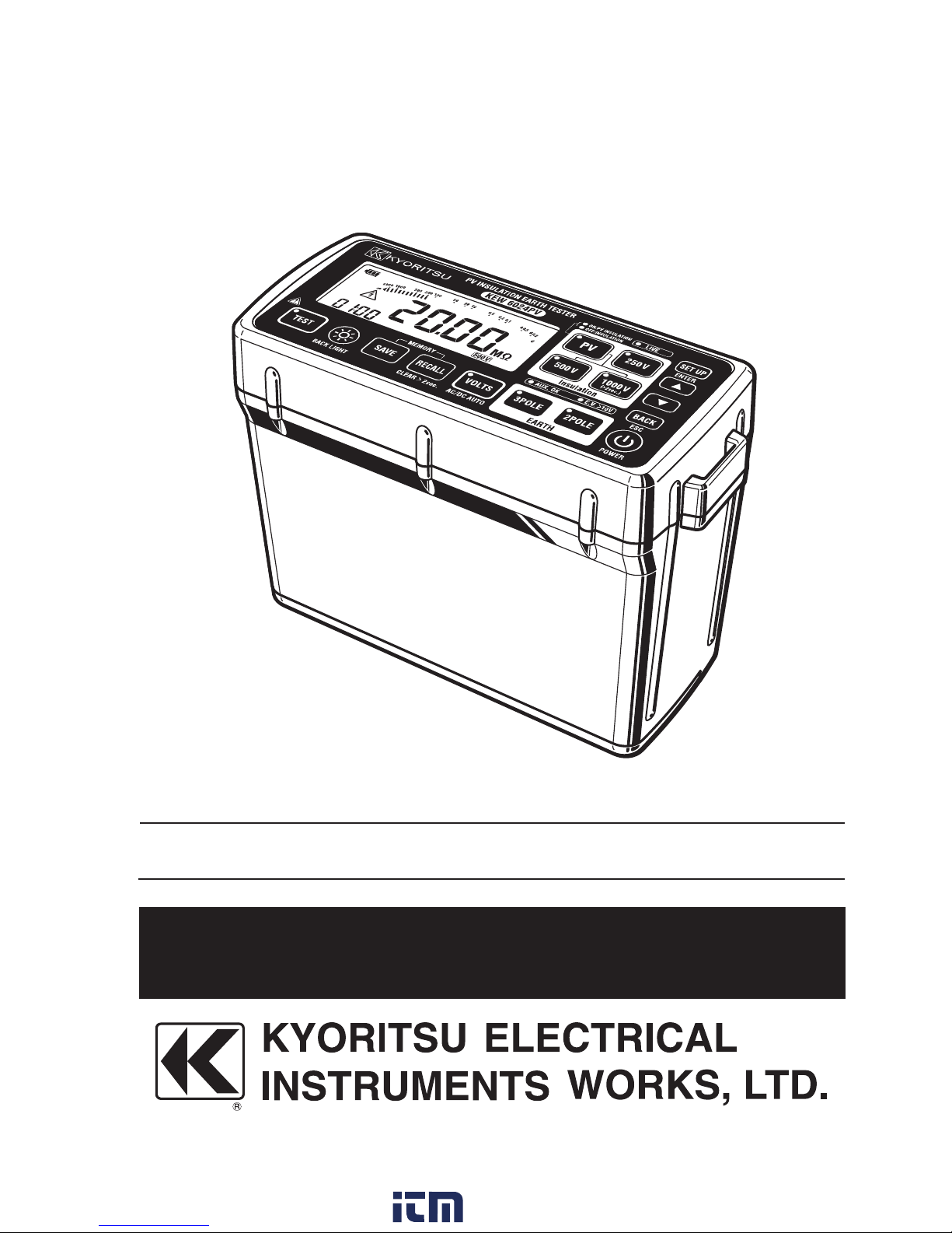
Instruction manual
PV insulation earth tester
KEW6024PV
www. .com
information@itm.com1.800.561.8187
Page 2

Contents
1. Safety warnings ................................................................................... 1
2. Features ............................................................................................... 7
3. Specifications ....................................................................................... 9
4. Name of parts .................................................................................... 14
5. Accessories ........................................................................................ 19
6. Preparations for measurement .......................................................... 21
6-1 Battery voltage check ................................................................... 21
6-2 Attaching metal tip/ adapter to test leads ...................................... 21
7. Insulation resistance measurement on PV systems .......................... 23
7-1 Measuring method ........................................................................ 25
8. Insulation resistance measurement ................................................... 31
8-1 Measuring method ........................................................................ 32
9. Earth resistance measurement .......................................................... 36
9-1 Measurement principle ................................................................. 36
9-2 Simplified measurement ............................................................... 37
9-3 Precision measurement (with MODEL7228A test leads) .............. 40
10. Voltage measurement ...................................................................... 44
10-1 Measuring method ...................................................................... 44
11. Alarm function .................................................................................. 46
11-1 Alarm function ............................................................................. 46
11-2 How to set alarm ......................................................................... 46
11-3 Display example – Alarm setting ................................................. 48
www. .com
information@itm.com1.800.561.8187
Page 3

12. Memory function .............................................................................. 49
12-1 How to save ................................................................................ 50
12-2 How to recall ............................................................................... 52
12-3 How to delete .............................................................................. 53
13. System clock settings ...................................................................... 54
13-1 How to adjust .............................................................................. 54
14. Data communication function .......................................................... 56
14-1 How to transfer data ...................................................................... 56
15. Battery replacement ......................................................................... 57
16. Shoulder strap and soft case attachment ........................................ 58
16-1 How to attach shoulder strap ...................................................... 58
16-2 How to attach soft case............................................................... 59
www. .com
information@itm.com1.800.561.8187
Page 4
1
1. Safety warnings
This instrument has been designed, manufactured and tested according to
IEC 61010: Safety requirements for Electronic measuring apparatus, and
delivered in the best condition after passing quality control tests.
This instruction manual contains warnings and safety rules which have to be
observed by the user to ensure safe operation of the instrument and to
maintain it in safe condition. Therefore, read through these operating
instructions before using the instrument.
WARNING
● Read through and understand the instructions contained in this manual
before starting to use the instrument.
● Keep the manual at hand to enable quick reference whenever necessary.
● The instrument is to be used only in its intended applications.
● Understand and follow all the safety instructions contained in the manual.
It is essential that the above instructions are adhered to. Failure to follow
the above instructions may cause injury and/or damage to the instrument.
The symbol indicated on the instrument, means that the user must
refer to the related parts in the manual for safe operation of the instrument.
It is essential to read the instructions wherever the symbol appears in the
manual.
DANGER : is reserved for conditions and actions that are likely to
cause serious or fatal injury.
WARNING : is reserved for conditions and actions that can cause
serious or fatal injury.
CAUTION : is reserved for conditions and actions that can cause
injury or instrument damage.
www. .com
information@itm.com1.800.561.8187
Page 5
2
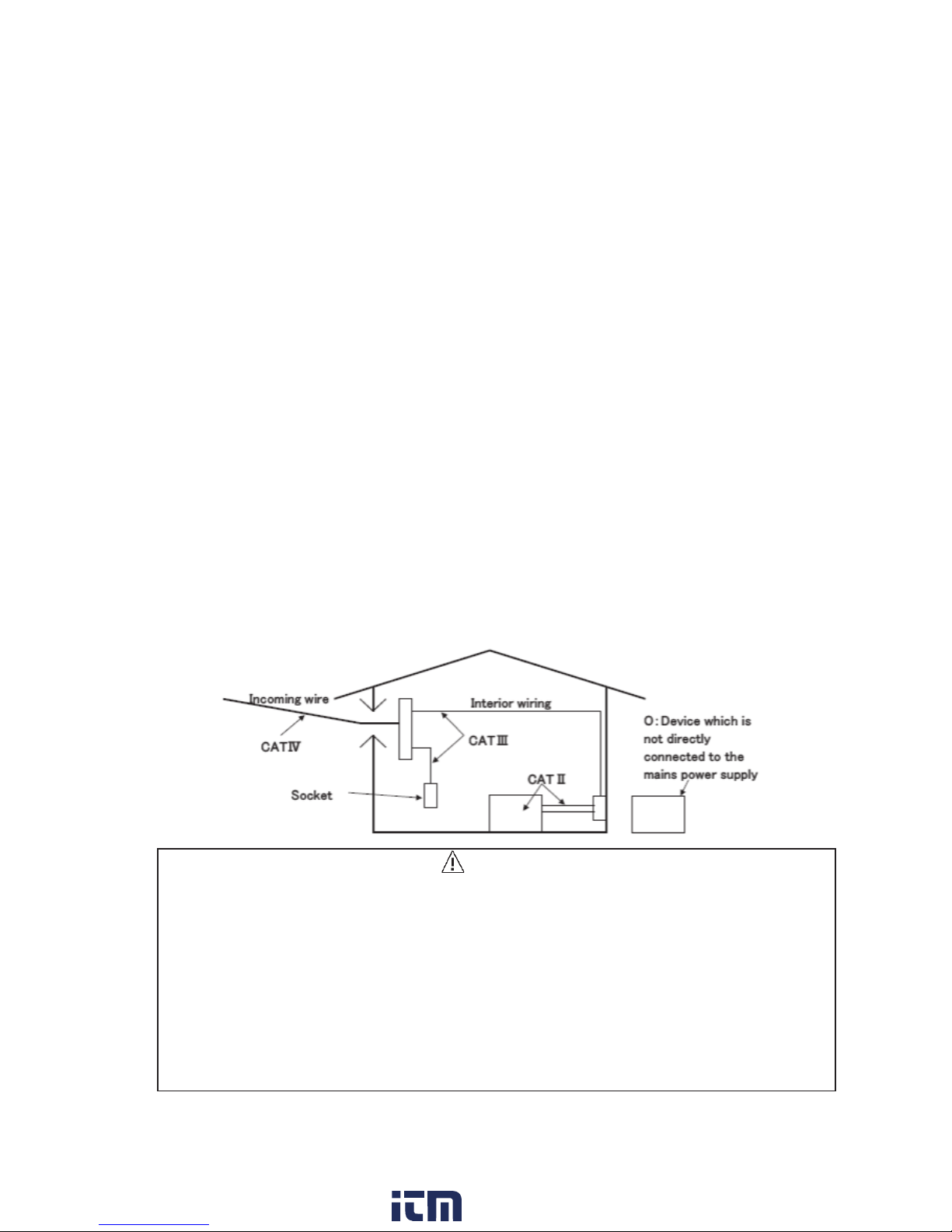
Measurement category
To ensure safe operation of measuring instruments, IEC 61010 establishes
safety standards for various electrical environments, categorized as O to
CAT IV, and called measurement categories. Higher-numbered categories
correspond to electrical environments with greater momentary energy, so a
measuring instrument designed for CAT III environments can endure greater
momentary energy than one designed for CAT II.
O (None, Other) : Circuits which are not directly connected to the mains
power supply.
CAT II : Electrical circuits of equipment connected to an AC
electrical outlet by a power cord.
CAT III : Primary electrical circuits of the equipment connected
directly to the distribution panel, and feeders from the
distribution panel to outlets.
CAT IV : The circuit from the service drop to the service
entrance, and to the power meter and primary
overcurrent protection device (distribution panel).
DANGER
● Never make measurements on a circuit in which earth potentials of
300 V or higher (in CAT IV)/ 600 V or higher (in CAT III) exist.
● Use the metal parts for test probes appropriate for the measurement
category they are used in.
● When test probes are connected to the instrument, the lower category
either of them belongs to is applied. Confirm that they are rated for the
measurement voltage of the instrument to be used.
www. .com
information@itm.com1.800.561.8187
Page 6
3
DANGER
● The instrument is to be used only in its intended applications or
conditions. Otherwise, safety functions equipped with the instrument
don’t work, and instrument damage or serious personal injury may
occur.
● Verify proper operation on a known source before taking actions as a
result of the indication of the instrument.
● Do not attempt to make measurement in the presence of flammable
gasses. Otherwise, the use of the instrument may cause sparking,
which can lead to an explosion.
● Never attempt to make connections of test leads if instrument surface or
your hand is wet.
● Be careful not to short-circuit a power line with the un-insulated metal
tip of the test probes to avoid injuries.
● Do not exceed the maximum allowable input of any measuring range.
● Do not press TEST button when connecting test leads to the instrument.
● Keep the battery compartment cover screwed and closed during a
measurement.
● Do not touch the circuit under test while measuring insulation resistance
or right after measurement to avoid electrical shock.
[Voltage test leads]
● Always use the test leads supplied with this instrument.
● Connect the test leads which are required for the measurement.
● Connect the test leads to the instrument first, and then to the measure-
ment line.
● Keep your fingers behind the barrier during a measurement.
Barrier provides protection against electrical shock and ensuring the
minimum required air and creepage distances.
● Never try to disconnect the test leads from the connectors of the
instrument during a measurement - while the instrument is energized.
● Do not touch two lines under test, at the same time, with the metal tips.
● Never touch the metal tips.
www. .com
information@itm.com1.800.561.8187
Page 7

4
WARNING
● The instrument is to be used only in its intended applications.
Understand and follow all the safety instructions contained in the
manual. Failure to follow the instructions may cause injury, instrument
damage and/or damage to the equipment under test. Kyoritsu is by no
means liable for any damage resulting from the instrument in
contradiction to these cautionary notes.
● Never attempt to make any measurements if the test leads and/or the
instrument has any structural abnormality, such as a crack or exposed
metal parts.
● Do not install substitute parts or make any modifications to the
instrument. Return the instrument to your local KYORITSU distributor for
repair or re-calibration in case of suspected faulty operation.
● Do not try to replace batteries if the surface of the instrument is wet.
● Connect the test leads firmly to the connectors.
● When replacing batteries, power off the instrument first, and then open
the battery compartment cover.
www. .com
information@itm.com1.800.561.8187
Page 8
5
CAUTION
● Select an appropriate function before starting a measurement.
● Power off the instrument after use, and disconnect the test leads.
Remove batteries if the instrument is to be stored and will not be in use
for a long period.
● Do not expose the instrument to direct sunlight, high temperature,
humidity or dew.
● Use a damp cloth with neutral detergent or water for cleaning the
instrument. Do not use abrasives or solvents.
● Wipe the instrument with a soft cloth, if it is wet, and store it after it’s dry.
Carefully read and observe the precautions with a mark of DANGER,
WARNING, CAUTION and Note: described in each chapter.
www. .com
information@itm.com1.800.561.8187
Page 9
6
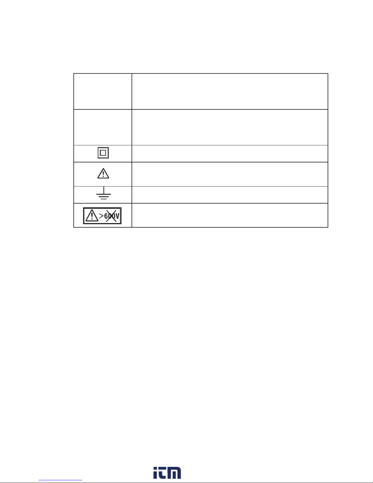
Symbols marked on the instrument
CAT III
Primary electrical circuits of the equipment connected
directly to the distribution panel, and feeders from the
distribution panel to outlets
CATIV
The circuit from the service drop to the service
entrance, and to the power meter and primary
over-current protection device (distribution panel)
Instrument with double or reinforced insulation
User must refer to the explanations in the instruction
manual.
Earth
Never use on a circuit with voltages higher than
600V.
www. .com
information@itm.com1.800.561.8187
Page 10

7
2. Features
KEW6024PV can measure insulation resistances of PV systems with open
voltages of 1000 V or less and of low-voltage installations with voltages of
600 V or less; moreover, earth resistance and AC/ DC voltage of distribution
lines and electrical appliances.
● Designed to meet the following safety standards.
IEC 61010-1,-2-030 CAT III 600V/ CAT IV 300V Pollution degree 2
IEC 61010-031
IEC 61557-1, -2, -5, -10
● Designed, produced and tested according to IEC60529 (IP54)
● Compact and light weight
● Backlight facilitating working in dimly lit areas
* The light automatically turns off if any button isn’t pressed for two minutes.
● The instrument automatically turns off if any button isn’t pressed for 10
minutes. This feature is disabled during a continuous measurement.
● Test probe with a remote control switch is supplied as standard accessory.
● Soft case – instrument is accessible while in use
● Strap belt allowing both hands free
● Replaceable metal tips are supplied as standard accessories
● Audible and visible live circuit warning
● Internal memory can store up to 1000 results. Data transfer and analysis to/
on a PC is possible by using the special software.
● Automatic AC/ DC detection at voltage measurement
www. .com
information@itm.com1.800.561.8187
Page 11

8
● Insulation resistance measurement
- When insulation resistance like a capacitive load is measured, electric
charges stored in a capacitive circuit are automatically discharged after
measurement. Discharge can be checked with the live warning LED, red
backlight, blinking symbol on the LCD and buzzer.
- Bar graph display
- Buzzer beeps when the measured value drops below or exceed the
pre-set threshold value.
- For safety reasons, a long press is required to select 1000V range.
It is possible to disable 1000V range.
* Special features for measurement on PV systems
- Measured voltages are displayed in stand-by mode.
- Elapsed time, after starting a measurement, is displayed with the
measured values.
- Auto-discharge with voltage display and also with the measured value
● Earth resistance measurement
- Measured earth voltage is displayed in stand-by mode. The LED lights up
if the measured voltage is relatively high.
- In precision measurement, warning indication will be displayed and the
LED lights up if the auxiliary earth resistance it too high.
- Easy to perform simplified measurement with two test probes on simplified
measurement function.
- Buzzer beeps when the measured value drops below or exceed the
pre-set threshold value.
www. .com
information@itm.com1.800.561.8187
Page 12
9
3. Specifications
● Measuring range and accuracy (23ºC±5ºC, RH 75% or less)
PV insulation resistance measurement
Rated measurement
voltage (DC)
500V 1000V
Range
(3-range auto)
20/ 200/ 2000MΩ
Display range
20MΩ range : 0.00 - 19.99 MΩ
200MΩ range : 15.0 - 208.9 MΩ
2000MΩ range : 159 - 2099 MΩ
Open voltage (DC)
Rated measurement voltage x
1 - 1.2 times
* Output voltage is to be divided by the
current-limiting resistor of 1 MΩ at
Earth terminal and the resistor at the
connected terminal.
Short-circuit current 1.5 mA or less
Measuring range 1.51 - 200.0 MΩ 1.51 – 1000 MΩ
Accuracy ±(1.5%rdg+5dgt)
Measuring range
0.00 - 1.50 MΩ
200.1 – 2000 MΩ
0.00 - 1.50 MΩ
1001 – 2000 MΩ
Accuracy ±(5%rdg+6dgt)
www. .com
information@itm.com1.800.561.8187
Page 13
10
Voltage/ Earth voltage measurement
Measuring range Display range (2-range auto) Accuracy
5 to 600 V AC
(45 - 65Hz)
300V range: 0.0 to 314.9 V
600V range: 240 to 629 V
±1%rdg±4dgt
±5 to ±1000 V DC
500V range: 0.0 to ±524.9 V
1000V range: ±400 to ±1049 V
Measuring method: True RMS
* Automatically detect AC/ DC when an input voltage is 5 V or higher and
show AC or DC symbol on the LCD.
* Input terminals are shown in the following table.
LINE-EARTH when selecting a voltage function
C(H)-E when selecting a simplified measurement function
P(S)-E when selecting a precision measurement function
Earth resistance measurement
Precision/
simplified
Range
(3-range auto)
Measuring
range
Display
range
Accuracy
*
1
20Ω range
0.00 - 2000 Ω
0.00 - 20.99 Ω ±3%rdg±0.1 Ω
200Ω range 16.0 - 209.9 Ω
±3%rdg±3dgt
2000Ω range 160 - 2099 Ω
Measuring method: Constant current inverter/ 825 Hz
20Ω range : approx. 3 mA
200Ω range : approx.2 mA
2000Ω range : approx. 1 mA
* For precision measurement, auxiliary earth resistance should be 100 Ω
±5% or less.
www. .com
information@itm.com1.800.561.8187
Page 14
11
Insulation resistance measurement
Rated measure-
ment voltage (DC)
250V 500V 1000V
Range
(3-range auto)
20/ 200/ 2000MΩ
Effective display
range
20MΩ range : 0.00 - 20.99 MΩ
200MΩ range : 16.0 - 209.9 MΩ
2000MΩ range : 160 - 2099 MΩ
Open-circuit
voltage (DC)
Rated measurement voltage x 1 - 1.2 times
Short-circuit current 1.5 mA or less
Rated current
(Lower limit resistance)
1.0 - 1.2 mA
0.25 MΩ 0.5 MΩ 1 MΩ
1st
effective
measuring
range
Measuring
range [MΩ]
1.51 - 100.0 1.51 - 200.0 1.51 - 1000
Mid. value 50 MΩ 50 MΩ 50 MΩ
Accuracy
(Intrinsic
error)
±1.5%rdg±5dgt
2nd
effective
measuring
range
Measuring
range [MΩ]
1.20 - 1.50
100.1 - 2000
1.20 - 1.50
200.1 - 2000
1.20 - 1.50
1001 - 2000
Accuracy
(Intrinsic
error)
±5%rdg±6dgt
Other measuring
range
0.00 - 1.19 MΩ
Accuracy
(Intrinsic error)
±5%rdg±6dgt
www. .com
information@itm.com1.800.561.8187
Page 15

12
Complies with the following standards:
● IEC 61010-1, -2 -030 CAT III 600V, CAT IV 300V Pollution degree 2
● IEC 61557-1, -2, -5, -10
● IEC 60529 IP54 (MODEL7196A/ IP40, MODEL7243/ IP42)
● IEC 61326-1, -2-2 Class B
● IEC 61010-031 MODEL7196A ......... CAT III 1000V, CAT IV 600V
MODEL7244A ......... CAT III 1000V, CAT IV 600V
*1
*1
Using the flat test prod is CAT II 600V rated.
* When test probes, sometimes with metal tips, are connected to the
instrument, the lower category either of them belongs to is applied.
● EN 50581 RoHS directive
● Location for use Altitude 2000m or less, in-door use
● Display Segment display with backlight
● Temperature & humidity range 23ºC±5ºC, RH85% or less
(accuracy guaranteed) (no condensation)
● Operating temperature -10ºC to 50ºC, RH80% or less (no condensation)
& humidity range * In a range of 40ºC to 50ºC, RH70% or less
● Storage temperature -20ºC to 60ºC, RH75% or less (no condensation)
● Withstand voltage 5160 V AC (50/60Hz) / 5 sec
Between electrical circuit and enclosure
● Insulation resistance 50MΩ or more/ 1000 V DC
Between electrical circuit and enclosure
● Auto-power-off Turns off the instrument automatically, after
a beep sound , if there is no function change,
range change or button press for about 10 min.
(*not work while performing a measurement)
● Backlight Automatically turns off if there is no activity for
about 2 min.
(*Auto-off is disabled during a measurement.)
● Dimensions 84(L) × 184(W) × 133(H) mm
● Weight Approx. 900g (including batteries)
● Power source Six size AA batteries
* Use of alkaline battery (LR6) is recommended.
www. .com
information@itm.com1.800.561.8187
Page 16
13
● Operating uncertainty
Operating uncertainty (B) is an error obtained under the nominal operating
conditions, and calculated with the intrinsic error (A), which is an error of the
instrument used, and the error (En) due to variations. According to
IEC61557, the maximum operating error should be within ± 30%.
● Operating uncertainty in insulation resistance measurements (IEC61557-2)
* Formula:
A Intrinsic uncertainty
E1 Not applicable
E2 Variation due to changing the Battery voltage
(till the battery indicator becomes empty” ”)
E3 Variation due to changing the temperature
(-10ºC to 50ºC)
* E1 is not applicable since this is a digital instrument.
* The measuring range to keep operating uncertainty of ± 30% is the same
as the 1st effective measuring range.
● Operating uncertainty in earth resistance measurements (IEC61557-5)
* Formula:
A Intrinsic uncertainty
E1 Not applicable
E2 Variation due to changing the Battery voltage
(till the battery indicator becomes empty” ”)
E3 Variation due to changing the temperature
(-10ºC to 50ºC)
E4 Variation due to series interference voltage
16·2/3 Hz, 50 Hz, 60 Hz, 10 V DC
400 Hz: 3 V
E5 Variation due to resistance of the auxiliary earth
electrode
20Ω range: 0 – 2 kΩ
200Ω range: 0 – 20 kΩ
2000Ω range: 0 – 50 kΩ
* The measuring range to keep operating uncertainty of ± 30% is within
5.00 Ω – 2000 Ω.
www. .com
information@itm.com1.800.561.8187
Page 17
14
● Possible number of measurements where battery voltage is within the
effective range (measurement of 5 sec., pause of 25 sec.)
Function
Test
resistor
Possible number of
measurements
PV Insulation
resistance
measurement
500V 0.5 MΩ Approx. 2500 times
1000V 1 MΩ Approx. 2000 times
Insulation
resistance
measurement
250V 0.25 MΩ
Approx. 2500 times
500V 0.5 MΩ
1000V 1 MΩ Approx. 1500 times
Earth measurement
(Simplified/ Precision)
10 Ω Approx. 2500 times
4. Name of parts
(1) Test lead
WARNING
Barrier is a part providing protection against electrical shock and ensuring
the minimum required air and creepage distances. Always keep your
fingers behind the barrier during a measurement.
Alligator clip
Flat test bar
Barrier
Test probe with remote control switch
www. .com
information@itm.com1.800.561.8187
Page 18
15
(2) Panel side
(3) Terminal part (Connector block)
Fig. 4-2
⑱
⑲ ⑳
Fig. 4-1
③ ④ ⑤ ⑥ ⑦
①
②
⑭
⑬
⑫
⑪
⑩
⑰ ⑯⑮
⑧⑨
www. .com
information@itm.com1.800.561.8187
Page 19
16
Items – Panel side Description
①
LCD LCD with backlight
②
Test button Starts/ stops a continuous measurement
③
Backlight button Turns on/ off the backlight
④
Save button Saves the measured result
⑤
Read/ delete button Reads out or deletes the saved data
⑥
Voltage button Measures voltages
⑦
Buttons for earth resistance
measurement
Selects simplified or precision earth
resistance measurement .
⑧ LED for aux. earth
Lights up in earth measurement to show the
auxiliary earth electrodes are connected properly.
⑨ Earth voltage warning LED
Lights up in earth measurement if the earth voltage
is relatively high.
⑩ Power button
Powers on/ off the instrument.
(A long press: 1 sec. or longer)
⑪ Back button Returns to the previous step at setting.
⑫
Down (cursor) button Decreases setting values.
⑬
Up (cursor) button Increases setting values.
⑭
Setup button Configures each setting.
⑮
LED for live circuit warning Alerts the circuit to be tested is live.
⑯
Button for insulation
resistance measurement
Selects insulation resistance measurement for PV
system or for the other objects.
⑰
Button for rated measure-
ment voltages
Selects a measurement voltage for insulation
resistance measurement. (A long press of
2 sec or longer is required to select 1000V.)
Items – Terminal part
Designated function
⑱
● LINE
● EARTH
● PV/ ordinary insulation measurement
● Earth (simplified) measurement
● Voltage measurement
⑲
● C(H)
● P(S)
● E
● Earth (precision) measurement
⑳
OPTICAL ADAPTER
For a connection of MODEL8212USB
to transfer saved data to PC
www. .com
information@itm.com1.800.561.8187
Page 20

17
(4) LCD
● Symbols common to all functions
Battery level indicator
Bar graph
(For PV insulation, insulation, earth measurements)
Segments for numerical display
Indicates “Over-range” status – the measured
value is exceeding the positive display limit.
e.g.: In earth measurements, “>2099Ω” may be
displayed. It indicates that the measured value is
exceeding 2099 Ω.
Indicates that a measurement completes and the
result is being held and displayed on the LCD.
Flashes to provide live circuit warning (for PV
insulation, insulation, earth measurement). This
mark also flashes during an insulation resistance
measurement.
Indicates that alarm function is enabled.
www. .com
information@itm.com1.800.561.8187
Page 21

18
● Symbols for PV/ ordinary insulation measurement
Appears to indicate the selected rated
measurement voltage
* 500V/1000V are selectable for PV system
Unit
Appears if 1000V button is pressed where 1000 V
is un-selectable.
● Symbols for earth measurement
・ Appears to indicate the selected function
Unit
・
Appears to alert the aux. earth resistance is too
high. (Precision measurement)
● Symbols for voltage/ earth voltage measurement
・ Indicates AC or DC
Unit
Appears to indicate negative voltage is measured.
Indicates “Over-range” status – the measured
value is exceeding the negative display limit.
e.g.: The LCD may show “< -1049V”. In this case, the
measured value is under “-1049 V”.
● Symbols for memory function
Indicates the running operation
Appears together with the measured result containing
dangerous high earth voltage.
Appears when showing site no. on the LCD.
Appears when showing data no. on the LCD.
www. .com
information@itm.com1.800.561.8187
Page 22

19
Long type and helpful to access
the distant measurement spot
Thin tip metal parts
5. Accessories
● Test leads
(1) Test probe MODEL7196A with remote control switch (red)
Fig. 5-1
(2) CAT II standard prod MODEL8072 (3) Extension prod MODEL8017
…1 pce …1 pce
Fig. 5-2 Fig. 5-3
* These metal tips are for MODEL7196A.
(5) Black cord with banana plugs at both ends
Fig. 5-4
+
(6) Alligator clip (7) Flat test bar
Fig. 5-5 Fig. 5-6
(8) L-shaped probe MODEL7243 (9) Hook type prod MODEL8016
(Optional accessory) (Optional accessory)
* Attached and used with MODEL7196A.
Fig. 5-8
Fig. 5-7
Changeable metal tips are available for MODEL7196A.
+
(4) A set of test leads with alligator clip MODEL7244A
To hook the probe on a conductor
www. .com
information@itm.com1.800.561.8187
Page 23

20
(11) Test leads for precision (12) Auxiliary earth spike
measurement MODEL7228A MODEL8032
Red 20m Yellow 10m Green 5m 215mm(L)×110mm(W)
*A pair of two spikes
+
Fig. 5-9 Fig. 5-10
+
(14) Cord reel (3 pcs) (13) Carrying bag
MODEL8200-03 MODEL9142
+
Fig. 5-11 Fig. 5-12
● Other accessories
(1) Carrying case MODEL9156
(2) Shoulder strap(with cord belt) MODEL9155
(3) Six AA alkaline batteries (LR6)
(4) Instruction manual
(6) USB adapter (7) CD(KEW Report)
Fig. 5-13 +
Fig. 5-14
+
(8) Instruction manual for MODEL8212 USB
USB
(10) Precision measurement cord set MODEL7245A (Optional accessory)
(5) USB adapter + KEW Report (software) MODEL8212 USB
www. .com
information@itm.com1.800.561.8187
Page 24

21
6. Preparations for measurement
6-1 Battery voltage check
(1) Please refer to “15. Battery replacement” in this manual and insert
batteries in KEW6024PV.
(2) Hold down the Power button at least 1 sec and power on the instrument.
* A long press of 1 sec or longer is required to power on/ off the instrument
in order to prevent a malfunction.
(3) Battery level indicator appears at the upper left on the LCD. Battery
voltage is extremely low if “ “ indicator is displayed. Replace batteries
with reference to “15. Battery replacement” to carry out further measurements. If empty “ ” indicator is displayed, battery voltage is below the
lower limit of the operating voltage. In such a condition, accuracy of the
measured result isn’t guaranteed.
When powering on the instrument with completely exhausted batteries,
empty battery indicator “ ” blinks in the LCD and also buzzer sounds
approx. 2 sec.
Use of AA alkaline battery (LR6) is recommended. Use of other batteries
may cause improper indication of battery level.
6-2 Attaching metal tip/ adapter to test leads
The following replaceable metal tips and adapters are available depending on
applications.
(1) For MODEL7196A:
1. MODEL8072 : Standard metal tip installed at a shipment
2. MODEL8017 : Long type and helpful to access the distant
3. MODEL8016 : Hook type prod (optional accessory)
www. .com
information@itm.com1.800.561.8187
Page 25

22
[How to replace the parts]
Detach the tip of Line probe by turning it counter-clockwise. Insert the metal
tip you want to use into the hexagon hole, and turn the tip part of the probe
clockwise to tighten firmly.
Note: Molded standard metal parts should be used in CAT III or IV
environment. Rated categories are written with the model name of each
parts. Always use the metal tips rated for the measurement category.
Fig. 6-1
(2) For MODEL7244A
Either of the following adapters can be attached to MODEL7244A.
1. Alligator clip
2. Flat test bar
[How to attach]
Firmly insert and connect the adapter to the end of the cord (with banana
plugs at both ends).
Fig. 6-2
DANGER
● To avoid getting electrical shocks, ensure that test leads are
disconnected from the instrument when replacing the metal tip or
adapter for test leads.
MODEL8017(CAT II)
Banana plugs, both ends
MODEL8072(CAT II)
MODEL8016 (CAT I)
Female
screw
Hexagon hole
Male screw
Metal tip
A
lligator clip
Flat test bar
www. .com
information@itm.com1.800.561.8187
Page 26

23
7. Insulation resistance measurement on
PV systems
Measure the insulation resistance of PV system to verify insulation of
PV array/ string. Before starting a measurement, confirm the voltage
value which can be applied to the object under test.
Note:
● Insulation resistance of PV array may be low if it is measured in rain or
high humidity. In addition, it takes longer time to get the result due to
large static capacitances (to earth) in such weather.
● Some objects have unstable insulation resistance and may cause unstable
readings.
● Select the insulation resistance function for PV system to measure the
insulation resistance of PV array.
● The instrument may give bleep during an insulation resistance measure-
ment, however, this is not a malfunction.
● The earth measuring terminal outputs positive voltage and the line
measuring terminal negative voltage.
● Connect the earth cord to the earth (ground) terminal at measure-
ment. It is recommended to connect the positive side to the earth side
when measuring insulation resistance against ground or when a part
of the object under test is earthed. Such connection is known to be
more suitable for insulation testing since insulation resistance values
measured with the positive side connected to earth are typically less
than those taken through the reversed connection.
www. .com
information@itm.com1.800.561.8187
Page 27

24
DANGER
● Be extremely careful not to touch the tip of test probe or circuit under test
to avoid electrical shock during insulation resistance measurement as
high voltage is present on the tip of the test probe continuously.
● Wipe the test probe with a soft cloth, if it is wet, and use it after it’s dry.
● Never make measurements with the battery compartment cover
removed.
WARNING
● Always disconnect power to the conductor under test before starting
insulation measurement. Do not attempt to make measurements on a
live conductor. Otherwise, it may damage the instrument.
● Before starting insulation resistance measurement on PV array, turn
off the main switch and disconnect the array from the solar inverter.
● Do not make measurement if any malfunction of PV array is suspected.
● Select and use ordinary insulation resistance measurement function
when measuring a conductor with P-N short-circuited.
● PV arrays generate dangerous voltages and current during the day.
Measures for work in high voltage environment should be taken and
appropriate protective gears must be used.
www. .com
information@itm.com1.800.561.8187
Page 28

25
7-1 Measuring method
DANGER
● Do not measure PV arrays with open-circuit voltage of 1000 V or more.
CAUTION
● Test and verify the insulation of P terminal prior to measuring insulation
resistance between N and earth terminals of PV array. If the measured
resistance value is low, do not perform further measurement so as not to
damage solar cells and modules.
(1) Press the PV button to select insulation resistance function for PV system.
The LCD shows “SOLA” about one second and the PV LED lights up.
(2) Connect the test leads as Fig. 7-1 shows.
MODEL7196A to LINE terminal, and MODEL7244A to EARTH terminal
Fig. 7-1
Red
Black
www. .com
information@itm.com1.800.561.8187
Page 29

26
(3) Follow the procedures described on the next page and open-circuit the
circuit to be measured.
CAUTION
This is just an example and the PV system connection may be different
from actual one. Always check the actual connection before starting
measurement.
Fig. 7-2
www. .com
information@itm.com1.800.561.8187
Page 30

27
1. Turn off the main switch of the solar PV installation following the
procedures according to the PV installation or solar Inverter instruction
manual.
2. Turn off all disconnection switches and disconnect each string.
3. In case of presence of SPDs (Surge Protection Devices) they must be
disconnected during all testing.
4. Before measurement, it is recommended to remove any electrical /
electronic device with lower withstand voltage rating than the test
voltage that is connected to the circuit under test.
5. If N-terminals of strings in circuit under test are earthed,
disconnect them before starting measurement.
(4) Confirm the voltage rating of the circuit under test, and press the button for
rated measurement voltage to select the voltage applied.
* A long press (2 sec or longer) is required to select 1000V.
* It is possible to disable 1000V range.
[How to disable/enable 1000V range]
1. Keep the 1000V button held down and power on the instrument.
2. Wait for about 5 seconds with the 1000V button held down to disable/
enable 1000V range.
[How to confirm 1000V is surely disabled]
The LCD shows “no” when pressing 1000V button.
www. .com
information@itm.com1.800.561.8187
Page 31

28
(5) Connect the earth test lead (MODEL7244A) to the earth terminal of the
circuit under test. Then, place the tip of remote probe (line) to P terminal
of the string.
Confirm that the voltage in the circuit under test is not high (usually less
than 50V). If high voltage is detected, impaired insulation is suspected.
The instrument may give live circuit warning while the subject string is
generating voltage, but can perform measurement where the voltage is
positive dc and less than the rated measurement voltage.
Note: Select the insulation resistance function for PV systems.
DANGER
● Never make measurements on a circuit in which earth potentials of
600 V or higher exist.
CAUTION
● Always turn off the breaker of the measurement line. The instrument
cannot make measurement on circuits energized with AC voltage or to
which negative DC voltage is being applied. Measurement in such live
circuit conditions may damage the instrument.
Display example
Voltage
Fig. 7-3
Solar inverter
Earth terminal
Disconnection
OFF
N terminal
P terminal
String (Solar cell array)
Black
Red
switc
h
www. .com
information@itm.com1.800.561.8187
Page 32

29
(6) Press the TEST button or remote control switch to start a continuous
measurement.
Note: Sometimes the insulation resistance value takes long time until
becomes stable because the string capacitance is big.
It is possible to relatively compare the insulation resistance value of each
string taking the reading after 1 minute of testing, so without waiting for
long time until the value is stable.
The LCD shows “>2099MΩ” when the measured result exceeds
the display range (over-range).
[Display example]
(7) Press TEST or remote control switch again to stop a continuous
measurement.
PV Insulation resistance – Measurement principle
Blin
k
Measured value
Elapsed time
Fig. 7-4
● Influences of voltage and current
generated by PV system are
subtracted.
● Flow of current I
2
stops when
static capacitance C is fully
charged.
Resistance = Voltage / Current
RX = V / (I
1
+ I2)
Fig. 7-5
LINE(-) P terminal N terminal
PV
Voltage:V
EARTH(+)
StaticResistance
Current:I1
Current:I2
capacitance:C:RX
www. .com
information@itm.com1.800.561.8187
Page 33

30
(8) [Auto discharge function]
This function allows electric charges stored in the capacitance of the
circuit under test to be automatically discharged after measurement.
Set the TEST button or remote control switch to off with the test leads
connected. Discharge can be monitored by the readings displayed at the
lower left of the LCD and also by live circuit warning LED, red backlight
and blinking mark.
Warning example
(9) Press the POWER button to power off the instrument when measurement
completes, and then disconnect the test leads from the instrument.
DANGER
● Never touch the circuit under test immediately after measurement.
Capacitances stored in the circuit may cause electric shock. Leave the
test leads connected to the circuit and do not touch the circuit until the
voltage value displayed at the lower left corner of the LCD becomes
positive dc value, live circuit warning LED turns off and audible warning
stops.
Blink
Voltage
Fig. 7-6
www. .com
information@itm.com1.800.561.8187
Page 34

31
8. Insulation resistance measurement
This instrument is used to measure insulation resistance in electric appliance
or circuit to inspect the insulation performance. Check the voltage rating of
the object to be tested before making measurement and select the voltage
applied to.
Note:
● Depending on the object being measured, displayed insulation resistance
value may not stabilize.
● The instrument may give bleep during an insulation resistance measurement, however, this is not a malfunction.
● Measurement time may be longer when measuring capacitive load.
● In insulation resistance measurement, the earth terminal outputs positive
voltage and the line terminal negative voltage.
● Connect the earth cord to the earth (ground) terminal at measurement.
It is recommended to connect the positive side to the earth side when
measuring insulation resistance against ground or when a part of the
object under test is earthed. Such connection is known to be more
suitable for insulation testing since insulation resistance values
measured with the positive side connected to earth are typically less
than those taken through the reversed connection.
CAUTION
● Be extremely careful not to touch the tip of test probe or circuit under test
to avoid electrical shock during insulation resistance measurement as
high voltage is present on the tip of the test probe continuously.
● Wipe the test probe with a soft cloth, if it is wet, and use it after it’s dry.
● Never make measurements with the battery compartment cover
removed.
www. .com
information@itm.com1.800.561.8187
Page 35

32
8-1 Measuring method
(1) Press the PV button to select insulation measurement function. The LCD
shows “InSU” for about one second, and the PV LED turns off.
(2) Connect the test leads as Fig. 8-1 shows.
MODEL7196A to LINE terminal, and MODEL7244A to EARTH terminal
Fig. 8-1
(3) Check the voltage rating of the object to be tested before making
measurement and select the voltage applied with the rated measurement voltage button.
● Hold down 1000V button two seconds or longer.
● It is possible to disable 1000V range.
[How to disable/enable 1000V range]
1. Keep the 1000V button held down and power on the instrument.
2. Wait for about 5 seconds with the 1000V button held down to disable/
enable 1000V range.
[How to confirm 1000V is surely disabled]
The LCD shows “no” when pressing 1000V button.
(4) Connect the earth test lead (MODEL7244A) to the earth terminal of the
circuit under test. Then, place the tip of remote probe (line) to the circuit
under test and press TEST or remote control switch to start a continuous
measurement. Press TEST or remote control switch again to stop
measurement.
Red
Black
www. .com
information@itm.com1.800.561.8187
Page 36

33
Voltage:V
Resistance:RX
Current:I
LINE(-)
EARTH
(+)
Resistance=Voltage / Current
RX=V / I
CAUTION
● Always disconnect power to the conductor under test before starting
insulation measurement. Do not attempt to make measurements on a
live conductor. Otherwise, it may damage the instrument.
Fig. 8-2
Fig. 8-3
Fig. 8-4
The LCD shows “>2099MΩ” when the measured result exceeds the
display range (over-range).
Display example
Earth terminal
Black
Red
Power
Load
OFF
Switch
Principle of insulation resistance
measurement
www. .com
information@itm.com1.800.561.8187
Page 37

34
(5) [Auto discharge function]
This function allows electric charges stored in the capacitance of the
circuit under test to be automatically discharged after measurement.
Set the TEST button or remote control switch to off with the test leads
connected. Discharge can be monitored by the readings displayed at the
lower left of the LCD and also by live circuit warning LED, red backlight
and blinking mark.
Warning
example
Pressing the BACK button during discharging allows you to monitor the
discharge voltage. In this case, the measured insulation value will be
cleared and go off from the screen.
(6) Press the POWER button and power off the instrument when measure-
ment completes, and then disconnect the test leads from the instrument.
DANGER
● Never touch the circuit under test immediately after measurement.
Capacitance stored in the circuit may cause electric shock. Leave the
test leads connected to the circuit and do not touch the circuit until
live circuit warning LED and warning mark stop blinking.
Blink
Voltage
Fig. 8-5
www. .com
information@itm.com1.800.561.8187
Page 38

35
(7) Output voltage characteristics
This instrument conforms to IEC61557-2. This standard specifies that the
rated current shall be at least 1 mA and thus defines the lower limit of the
insulation resistance to maintain the rated voltage at the measurement
terminal. (See the graph below.)
This value is calculated by dividing the rated voltage by rated current.
ie., in case that the rated voltage is 500 V, the lower limit of the insulation
resistance is found as follows.
Divide 500 V by 1mA equals 0.5 MΩ.
That is, insulation resistance of 0.5 MΩ or more is required to provide the
rated voltage to the instrument.
Rated voltage 250 V 500 V 1000 V
Lower limit of insulation resistance to
supply rated measurement current (1 mA)
0.25 MΩ 0.5 MΩ 1 MΩ
Fig. 8-6
Insulation resistance(MΩ)
Output voltage(V)
range
1000V
range
500V
range
250V
www. .com
information@itm.com1.800.561.8187
Page 39

36
9. Earth resistance measurement
With the earth resistance measurement function of this instrument, earth
resistance of power distribution lines, in-house wiring system and electrical
appliances can be measured.
DANGER
● The instrument will produce a maximum voltage of about 50 V between
C (H) and E terminals at earth resistance measurement. Take enough
caution to avoid electric shock hazard.
● When measuring earth voltage, do not apply voltage greater than 600 V
between measuring terminals.
● When measuring earth resistance, do not apply voltage between
measuring terminals.
9-1 Measurement principle
This instrument makes earth resistance measurement with fall-of-potential
method, which is a method to obtain earth resistance value Rx by applying
AC constant current I between the measurement object E (earth electrode)
and C (current electrode), and finding out the potential difference V between
E and P (potential electrode).
Rx = V / I
Fig. 9-1
P (Potential)
Constant current generator
C (Current)
Voltmeter
E (Earth)
www. .com
information@itm.com1.800.561.8187
Page 40

37
9-2 Simplified measurement
Use this method when the auxiliary earth spike cannot be stuck. In this
method, an existing earth electrode with a low earth resistance, such as a
metal water pipe, a common earth of a commercial power supply and an
earth terminal of a building, can be used with two-pole method (E and P).
(1) Connect the test leads as Fig. 9-2 shows.
MODEL7196A to LINE (C) terminal, and MODEL7244A to EARTH (E)
terminal
Fig. 9-2
(2) Wiring
Make connection as shown in the following figure.
Connection using common earth Connection using socket outlet
of commercial power supply
Fig. 9-3 Fig. 9-4
Red
Black
E Black C Red
Power
Load
re Rx
PN
E
E Black C Red
www. .com
information@itm.com1.800.561.8187
Page 41

38
DANGER
● Use a voltage detector to check a common earth of commercial power
supply.
● Do not use this instrument to check a common earth of commercial
power supply.
A danger will be caused because the voltage may not be displayed even
in case of a live conductor, when the connection of the earth electrode to
be measured has come off, or when the connection of the test leads of
the instrument is not correct etc.
(3) Earth voltage check
● Press the 2POLE button and select simplified measurement function.
Then, 2POLE mark is displayed on the LCD.
● In the connection state of Fig. 9-3 or 9-4, check the earth voltage
displayed on the LCD. The earth voltage displayed in this state is the
voltage between C(H) and E terminals.
Display example
Fig. 9-5
Make sure that the voltage is less than 10 V. When the display reads 10 V
or more, a warning LED as shown below lights up. (The warning LED
lights up at 5 V or more for an earth voltage of 400 Hz.)
Red LED lights up. Fig. 9-6
Excessive errors in earth resistance measurement may be caused in the
condition that warning LED for high earth voltage is lighting up. To avoid
this, make measurement after reducing the voltage by turning off the
power supply of the equipment under test etc.
Displayed at the lower
left of the LCD display
www. .com
information@itm.com1.800.561.8187
Page 42

39
(4) Measurement
● Press TEST or the remote control switch to start a continuous
measurement. Press TEST or remote control switch again to stop
measurement.
Display example
Fig. 9-7
The LCD shows “>2099Ω” when the measured result exceeds the
display range (over-range).
(5) Simplified measurement value
Two-pole method is used for simplified measurement. In this method,
earth resistance value re of earth electrode connected to terminal C(H) see Fig. 9-3 - is added to true earth resistance value Rx and shown as an
indicated value Re.
Re = Rx + re
If the re is known beforehand, true earth resistance value Rx is calculated
as follows.
Rx (true resistance) = Re - re
www. .com
information@itm.com1.800.561.8187
Page 43

40
9-3 Precision measurement (with MODEL7228A test leads)
(1) Connection
Switch the auxiliary earth spikes P(S) and C(H) into the ground deeply.
They should be aligned at an interval of 5 - 10 m from the earthed
equipment under test. Connect the green wire to the earthed equipment
under test, the yellow wire to the auxiliary earth spike P(S) and the red
wire to auxiliary earth spike C(H) from terminals E, P(S) and C(H) of the
instrument in order.
Fig. 9-8
MODEL7228A(with cord reel)
Fig.
9-9
Fig. 9-10
Note:
Make sure to stick the auxiliary earth spikes in the moist part of the soil.
Give enough water where the spikes have to be stuck into the dry, stony or
sandy part of the earth so that it may become moist.
In case of concrete, lay the auxiliary earth spike down and water it, or put a
wet cloth etc. on the spike when making measurement.
Use MODEL7228A test leads for
measurement.
Connect the red wire (20m) to C(H)
terminal, yellow wire (10m) to P(S)
terminal and green wire to E terminal.
GreenRed Yello
w
CPE
C
P
E
A
uxiliary earth spikes
Earth electrode under test
Red
Yellow
Green
www. .com
information@itm.com1.800.561.8187
Page 44

41
(2) Earth voltage check
● Press the 3POLE button and select precision measurement function.
Then, 3POLE mark is displayed on the LCD.
● In the connection state of Fig. 9-10, check the earth voltage displayed
on the LCD. The earth voltage displayed in this state is the voltage
between P(S) and E terminals.
Display example
Fig. 9-11
Make sure that the voltage is less than 10 V. When the display reads 10 V
or more, the warning LED as shown below lights up. (The warning LED
lights up at 5 V or more for an earth voltage of 400 Hz.)
Red LED lights up. Fig. 9-12
Excessive errors in earth resistance measurement may be caused in the
condition that warning LED for high earth voltage is lighting up. To avoid
this, make measurement after reducing the voltage by turning off the
power supply of the equipment under test etc.
Displayed at the lower
left of the LCD display.
www. .com
information@itm.com1.800.561.8187
Page 45

42
(3) Measurement
Press TEST or the remote control switch to start a continuous measurement. Press TEST or remote control switch again to stop measurement.
Fig. 9-13
The LCD shows “>2099Ω” when the measured result exceeds the
display range (over-range).
(4) Auxiliary earth resistance
If the auxiliary earth resistance is within the allowable range and doesn’t
affect measurement, the LED (AUX. OK) lights up.
Green LED lights up. Fig. 9-14
If the auxiliary resistance of auxiliary spick P or C is too high to make
measurement, the display reads “RP_H” or “RC_H”. Recheck the
connection of test leads and the earth resistance of auxiliary earth spike.
When RP is too high: When RC is too high:
Fig. 9-15 Fig. 9-16
Display example
www. .com
information@itm.com1.800.561.8187
Page 46

43
DANGER
● If measurement is made with the test leads twisted or in touch with each
other, the reading of the instrument may be affected by induction. When
connecting the test leads, make sure that they are separated.
● If earth resistance of auxiliary earth spikes is too large, it may result in
inaccurate measurement. Make sure to stick the auxiliary earth spike
P(S) and C(H) into the moist part of the earth carefully, and ensure
sufficient connections between the respective connections.
● If auxiliary earth resistance is higher than 100 times of the upper limit
value of the selected measurement range, the measured result may be
displayed on the next higher range.
e.g.:
When the measured result is 10 Ω, the LCD normally shows “10.00Ω”,
however, it may show “10Ω”.
www. .com
information@itm.com1.800.561.8187
Page 47

44
10. Voltage measurement
DANGER
● Do not apply a voltage exceeding the maximum allowable input (600 V
AC/ 1000 V DC) to the insteument and between terminals.
10-1 Measuring method
(1) Press the VOLTS button to select voltage measurement function.
(2) Connect the test leads as Fig. 10-1 shows.
● MODEL7196A to LINE terminal, and
MODEL7244A to EARTH terminal
Fig. 10-1
(3) Connect the black test lead to the earth side of the circuit under test and
the red remote probe to the line side.
Fig. 10-2
Red
Black
Select voltage function.
Never press
CAUTION
TEST button.
CAUTION
Never press
remote button.
www. .com
information@itm.com1.800.561.8187
Page 48

45
(4) Check the reading on the LCD without pressing TEST or remote control
button. The instrument detects AC/ DC automatically, and shows “DC”
for dc input and “AC” for ac input on the LCD.
● As for dc inputs, the negative polarity sign “-“ is displayed to the left of
the reading where the line probe side is charged with negative polarity.
● When the measured voltage is less than 5 V, any of AC, DC or polarity
symbols don’t appear.
When the measured result exceeds the display range (over-range), the
LCD reads as follows.
AC voltage : > 629 V
Positive DC voltage : > 1049 V
Negative DC voltage : <- 1049 V
Fig. 10-3
Display example
Measured value
Current time
(Hour: Min.)
www. .com
information@itm.com1.800.561.8187
Page 49

46
11. Alarm function
11-1 Alarm function
Compare the measured result and the pre-set reference value on PV
insulation measurement, insulation measurement and earth measurement
functions and notify the result to the user with buzzer.
● Select any of the following reference values or enter a desired value.
Different values can be set for each range.
Function
Alarm function – Reference value
Insulation meas. (MΩ)
& PV insulation meas.
0.1, 0.2, 0.25, 0.4, 0.5, 1, 2, 3, 5,
10, 20, 30, 50, 100
Earth meas. (Ω)
1, 2, 3, 4, 5, 10, 20, 30, 50, 100,
200, 300, 500, 1000
● When “>” is selected at alarm setting, buzzer sounds and blinking “>” mark
and the pre-set reference value are displayed when the measured value
exceeds the reference value.
● When “<” is selected at setting, buzzer sounds and blinking “<” mark and
the pre-set reference value are displayed when the measured value is
less than the reference value.
● This function is disabled if “OFF” is selected. (Default setting: OFF)
11-2 How to set alarm
The following figures (Fig. 11-1 to 11-7) show how to set alarm. The setting
procedures described below are common to all functions. Pressing the
BACK button in setting process returns to the previous step.
Stand-by state
Fig. 11-1
1. Press SET UP.
Blink
Fig. 11-2
2. Press cursor button (△ or ▽ ) to
select “>”, “<” or “OFF”.
www. .com
information@itm.com1.800.561.8187
Page 50

47
3. Press SET UP.
4. Press cursor button (ڹ or ۃ) to
select any reference value.
(Select “Any” to enter a desired value.)
5. Press SET UP.
Blink
Setting completes
when selecting a
reference value.
When entering a desired value:
7. Press SET UP.
Alarm setting completes.
Fig. 11-3
Fig. 11-4
Fig. 11-5
Fig. 11-6
Fig. 11-7
10. Repeat step 8. and 9. to select a
desired number for the second and
third digit.
6. Press cursor button (ᇞ or佇) to set
decimal place.
8. Press cursor button (ᇞor 佇) to move
the blinking cursor onto the first digit.
11. Setting completes when the last
digit has been set.
9. Press
SET UP
.
Blink
www. .com
information@itm.com1.800.561.8187
Page 51

48
11-3 Display example – Alarm setting
Fig. 11-8 Fig. 11-9
Fig. 11-10 Fig. 11-11
Insulation measurement
(stand-by state)
Insulation measurement
(during measurement)
Earth measurement
(during measurement)
● When “>” has been selected, buzzer sounds and blinking “>” mark
and the pre-set reference value are displayed when the measured
value exceeds the reference value.
● When “<” is selected at setting, buzzer sounds and blinking “<” mark
and the pre-set reference value are displayed when the measured
value is less than the reference value.
● Indications remain the same at PV insulation measurement. Buzzer
sounds when the measured value is greater or lower than the
pre-set reference value.
Alarm mark and the pre-set reference value are displayed while alarm function is
enabled. When starting a PV insulation or earth resistance measurement, the
alarm mark will only be displayed.
Earth measurement
(stand-by state)
www. .com
information@itm.com1.800.561.8187
Page 52

49
12. Memory function
Results measured in PV insulation resistance, voltage, insulation resistance
and earth resistance measurements can be saved in the memory of the
instrument. (max. 1000) In addition, two different location numbers can be
allocated to each data.
Parameters saved
with the results
Detail Range
Saved time
and date
Time and date when the data saved is
recorded automatically.
Note:
● Note the measured time and date.
● Data transfer to PC is required to view
the saved time and date.
-
Data no.
Select and allocate a data no. to save a
result. Number will automatically be
given in sequence.
0 - 999
Site no. 1
Specify and allocate a desired site no. to
a measured data. (E.g.: Give a specific
no. to the building where the measure-
ment is done.)
0 - 99
Site no. 2
Specify and allocate a desired site no. to
a measured data. (E.g.: Give a specific
no. to the distribution panel where the
measurement is done.)
0 - 99
www. .com
information@itm.com1.800.561.8187
Page 53

50
12-1 How to save
● Quick save
Pressing SAV E at any of steps 3 through 7 can save the data without
entering Site no. 1, 2 and Data no. In this case, the instrument automatically assigns each number; Site no. 1 and 2 will be the same
as the last time and Data no. will be the previous number plus one.
2. Press SAV E .
(In case of voltage measurement,
press SAV E during a measurement.)
1. Confirm the measured value is held
right after a measurement.
3. Press cursor button (△ or ▽) to
set Site no 1.
Blink
Blink
Site no.1
4. Press SET UP.
Site no. 2
9. Quick save
Fig. 12-1
Fig. 12-2
Fig. 12-3
5. Press cursor button (△ or ▽) to
set Site no 2.
www. .com
information@itm.com1.800.561.8187
Page 54

51
6. Press SET UP.
7. Press cursor button (ᇞor 佇) to
set Data no. The displayed
number is the previous number
plus one.
Blink
Data save completes.
2 sec later
Returns to the state at the beginning.
(Measured result is held and displayed)
9. Quick save
Fig. 12-4
Data no.
Fig. 12-5
Fig. 12-6
8. Press SET UP.
www. .com
information@itm.com1.800.561.8187
Page 55

52
12-2 How to recall
Follow the procedures below to recall the saved data.
Note:
● When recalling PV insulation resistance data, the LED on PV button
lights up.
● When recalling the data saved with earth voltage alert, “ ” mark
is also displayed on the LCD.
Stand-by state
1. Stand by or data hold state.
2. Press RECALL.
4. Press SET UP to check the Site no. 1
and 2.
Data no.
Site no. 2
Site no.1
The warning mark appears when
recalling data for which earth
voltage alert was given.
Fig. 12-7
Fig. 12-8
Fig. 12-9
3. Saved data is displayed.
Press cursor button (△ or ▽) to
select a desired Data no.
Fig. 12-10
www. .com
information@itm.com1.800.561.8187
Page 56

53
12-3 How to delete
Follow the procedures below to delete the saved data.
Stand-by state
1. Stand by or data hold state.
2. Hold down RECALL 2 sec.
icon will then be displayed.
Hold down
2 sec.
3. Press cursor button (△ or ▽) to
select the Data no. of the data you wish
to delete.
4. Press SET UP.
5. DEL icon blinks.
Blink
6. Press SET UP.
Data has been deleted.
To delete all the saved data,
select “ALL” which comes
before the number 0 and
after the number 999.
Fig. 12-14
Fig. 12-13
Fig. 12-12
Fig. 12-11
Long press of
2 sec :Delete
www. .com
information@itm.com1.800.561.8187
Page 57

54
13. System clock settings
To adjust the date and time of internal system clock, follow the steps below.
When saving measured results in the internal memory, date and time
information will be saved together.
* Not the date and time when the measurement was performed.
13-1 How to adjust
● The following figures show how to set the system clock.
● The clock setting is allowed only on stand-by screen for voltage
measurement.
● Pressing the BACK button in setting process returns to the previous step.
1. Press SET UP.
2. First, set year. Press cursor button
(ᇞor 佇) to adjust the second digit
from the right.
3. Press
SET UP
.
Blink
Fig. 13-1
Fig. 13-2
Fig. 13-3
4. Press cursor button (ᇞ or佇) to
adjust the last digit.
Blink
Stand-by state: voltage measurement
www. .com
information@itm.com1.800.561.8187
Page 58

55
Year
6. Press cursor button (
ᇞ or
佇
) to adjust
month. Previously adjusted year will be
displayed at the lower left corner.
Month. Day
10. Adjust hour according to the same
procedure for adjusting year. Previously
adjusted month and day will be
displayed at the lower left corner.
5. Press SET UP.
Month
Fig. 13-4
7. Press SET UP.
Day
Blink
Fig. 13-5
8. Now adjust day.
* Returns to the top of
year setting.
9. Press SET UP.
Fig. 13-6
Blink
11. Press SET UP.
12. Adjust minute according to the same
procedure for adjusting year.
Fig. 13-7
Blink
Minute
Hour
13. Press
SET UP
.
Settings complete.
Fig. 13-8
Blink
www. .com
information@itm.com1.800.561.8187
Page 59

56
14. Data communication function
Data transfer to PC is possible by using our optical adapter MODEL8212
USB.
14-1 How to transfer data
(1) Install “KEW Report” first before trying to transfer data to PC.
(2) Connect the plug of MODEL8212 USB to the USB port on the PC.
(3) Disconnect the test leads from the instrument, and then connect
MODEL8212 USB as follows.
(4) Power on the instrument. * Selecting any function is just all right.
(5) Run “KEW Report” and click Download command. Then the data will be
transferred from the instrument to PC.
For further details, please refer to the instruction manual for 8212USB
and HELP for KEW Report.
Fig. 14-1
www. .com
information@itm.com1.800.561.8187
Page 60

57
15. Battery replacement
When the battery indicator shows empty “ ”, replace the batteries with
new ones.
DANGER
● Do not open the battery compartment cover if the instrument is wet.
● Never attempt to replace batteries during a measurement. In order to
avoid getting electrical shock, ensure that the instrument is powered off
and test leads are disconnected from the instrument before replacing
batteries.
● The battery compartment cover must be closed and screwed before
starting a measurement. Otherwise, electrical shock hazard may be
caused.
CAUTION
● Do not mix new and old batteries or mix different types of batteries.
● Install batteries in correct polarity as marked inside.
(1) Power off the instrument, and then disconnect the test leads.
(2) Loosen two screws which are fixing the battery compartment cover, and
remove the cover.
(3) Replace all six batteries with new ones at the same time. Be sure that the
battery polarity is correct.
Use of six size AA alkaline batteries (LR6) is recommended.
(4) Install the battery compartment cover, and tighten two screws for the cover.
Fig. 15-1
www. .com
information@itm.com1.800.561.8187
Page 61

58
16. Shoulder strap and soft case attachment
16-1 How to attach shoulder strap
(1) Run the side belt through the slider
as Fig. 16-1 shows. (for two side belts)
(3) Attach the shoulder strap to the
side belt as Fig. 16-3 shows.
Fig. 16-1
(2) Attach the side belt as
Fig. 16-2 shows.
(to both sides)
Fig. 16-3
A
djust the slider to alter the length of strap.
Side belt
Slider
Shoulder strap
Fig. 16-2
www. .com
information@itm.com1.800.561.8187
Page 62

59
16-2 How to attach soft case
Put the instrument into the soft case as Fig. 16-4 shows. Follow the arrows
with number 1 and 2 in sequence.
(1) Run the side belts though the slits on the soft case, and put the instrument
into the soft case.
(2) Place the partition box to the bottom of the soft case. Test leads can be
stored in this box.
Fig. 16-4
Instrument
Partition
box
Soft case
①
②
Cord belt
Test leads
Tie the test leads
to the shoulder
stra
p
.
Shoulder strap
Fig. 16-5
Complete
www. .com
information@itm.com1.800.561.8187
 Loading...