

Page 1
INSTRUCTION MANUAL
1. Features
●
Designed to meet international safety standards.
IEC61010-1.IEC61010-031 & IEC61010-2-032
Measurement Category (CAT.) IV 600V
Pollution Degree 2
●
Double molded main body provides comfortable
single handed grip
●
Data Hold Function
●
LCD Backlight function to facilitate working at dimly
lit situations.
●
REL func tion t o in dicate meas urem ent variati on
(Current, voltage, Resistance measurement)
●
MIN/MAX function enables easy reading of min &
max value during measurement.
●
PEAK Hold Function enables Peak value measurement of starting current. (only at ACA Range)
●
With Continuity & Diode Check Function
●
Capacity measurement of capacitors
●
Temperature measurement, switchable between ℃
and ℉
●
NCV (Non Contact Voltage) Function for wiring check
●
600V input protection
●
Sleep Function to extend battery life
●
With Bar Graph, 6039 count display
2. Safety Warnings
This instrument has been designed,manufactured and
tested according to IEC 61010: Safety requirements
for Electronic Measuring apparatus, and delivered in
the best condition after passed the inspection.
This instruction manual contains warnings and safety
rules which must be observed by the user
to ensure
safe operation of the instrument and retain it in safe
condition.
Therefore, read through these operating instructions
before using the instrument.
# WARNING
●
Read through and under stand the instr uctio ns
con t a i n e d in th i s ma n ual bef o re us i n g th e
instrument.
●
Keep the manual at hand to enable quick reference
whenever necessary.
●
The instrument is to be used only in its intended
applications.
●
Understand and follow all the safety instructions
contained in the manual.
●
It is essen tia l that th e abo ve i nst ruc tio ns a re
adhered to.
●
Failure to follow the above instructions may cause
in jur y, i nst rum ent d amag e and /or d ama ge to
equipment under test.
The symbol # indicated on the instrument means
that the user must refer to the related parts in the
manual for safe oper ation of the instrument. It is
essential to read the instructions wherever the #
symbol appears in the manual.
# DANGER is reserved for conditions and actions
that are likely to cause serious or fatal injury.
# WARNING is reserved for conditions and actions
that can cause serious or fatal injury.
# CAUTION is reserved for conditions and actions
that can cause injury or instrument damage.
●
Marks listed in t he table below are used on this
instrument.
#
User must refer to the manual.
Instrument with double or reinforced insulation
Indicates that this instrument can clamp on
bare conductors when measuring a voltage
corresponding to the applicable measurement
category, which is marked next to this symbol.
AC
DC
AC & DC
Th i s in s t r u me n t sa t i s f ie s th e ma r k i n g
requirement defined in the WEEE Directive.
This symbol indicates separate collection for
electrical and electronic equipment.
# DANGER
●
Never make measu rement on a circuit in which
voltage over AC600V exists.
●
Do n ot att empt t o make m easu re m ent i n the
presen ce of flammable gasses. Otherwise, the
use of the instrument may cause sparking, which
can lead to an explosion.
●
Transformer jaw tips are designed not to short the
circu it under test. I f equipment u nd er test has
expose d con d u c t i v e pa r t s , ho w e v e r, ex t r a
pre cauti o n sho u l d be tak e n t o mini m i ze th e
possibility of shorting.
●
Never attempt to use the instrument if its surface
or your hand is wet.
●
Do not exceed the maximum allowable input of
any measuring range.
●
N e v e r o p en t h e B a t te ry co v er du r in g a
measurement.
●
The instrument is to be used only in its intended
ap pli cati ons o r cond iti ons . Othe rwi se, sa fet y
funct ions equipped with the instru ment doesn't
work, and instrument damage or serious personal
injury may be caused.
# WARNING
●
Nev e r at t empt to make measu r ement if any
abnor mal conditions, s uch as brok en case and
exposed metal parts are found on the instrument.
●
Do not rotate the Function Switch while the test
leads are being connected.
●
Do not install subst i t u te pa r t s or make any
modification to the instrument. For repair or recalibration, return the i nstrument to your local
distributor from where it was purchased.
●
Do not try to replace the batteries if the surface of
the instrument is wet.
●
Di sconn ect all t he c ords an d cable s from t he
object under test an d power off th e instrument
be fore op eni ng th e Battery Co ver f or Ba tte ry
replacement.
●
Verify proper operation on a known source before
use or taking action as a result of the indication of
the instrument.
# CAUTION
●
Set the Function Switch to an appropriate position
before starting measurement.
●
Firmly insert the test leads.
●
Disconnect the test leads from the instrument for
current measurement.
●
Do not expose the instrument to the direct sun,
high temperature and humidity or dewfall.
●
Alti tude 2000m or less. Approp riate operati ng
temperature is within 0℃ and 40℃.
●
This instrument isn't dust & water proofed. Keep
away from dust and water.
●
Be sure to power off the instrument after use.
When the instrument will not be in use for a long
peri od, pla ce i t in sto rage af ter removin g the
batteries.
●
Use a cloth dipped in water or neutral detergent
for cleaning the instrument. Do not use abrasives
or solvents.
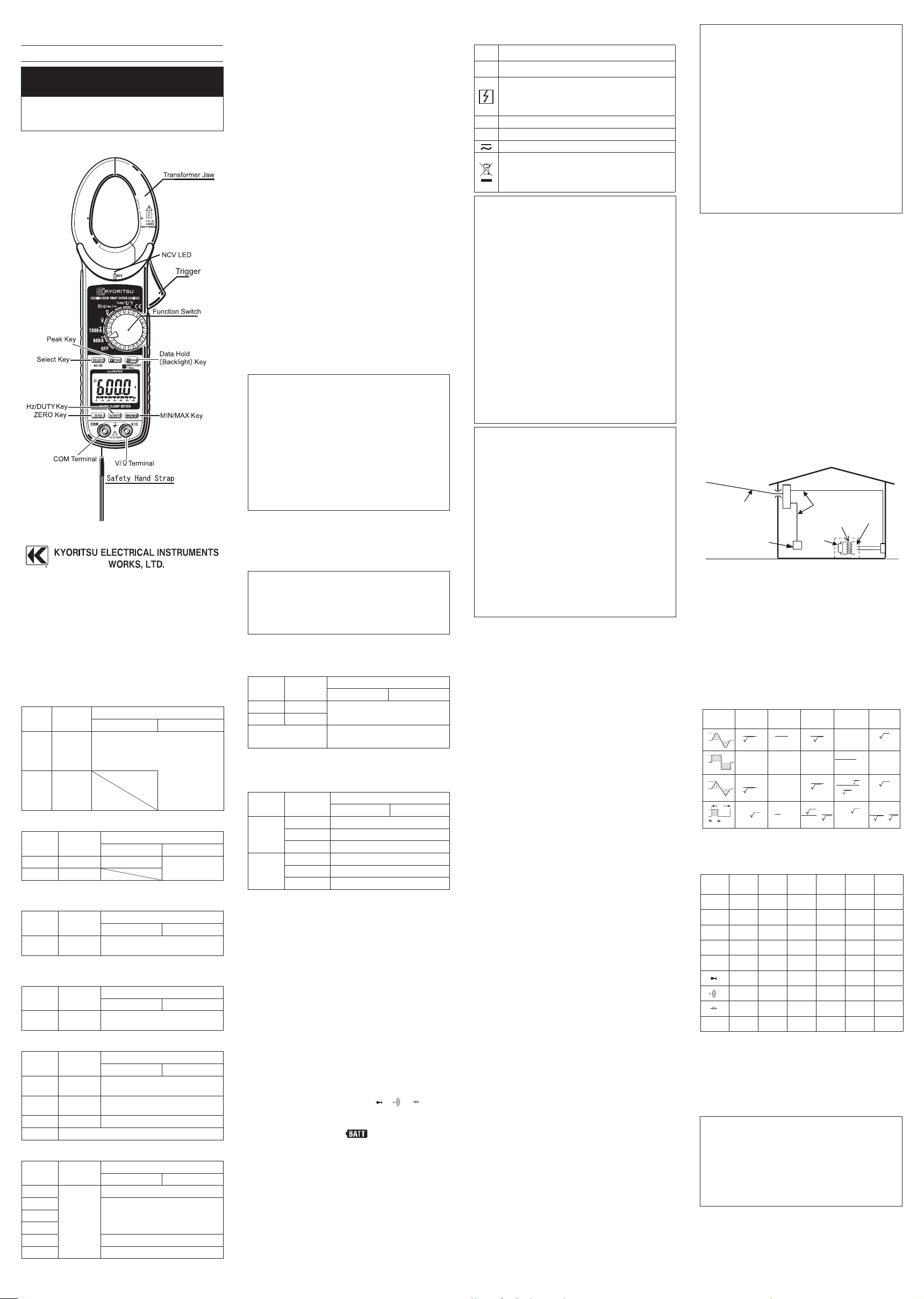
Measurement categories (Over-voltage categories)
To ensure safe operation of measuring instruments,
IEC61010 establishes safety standards for various
electrical environments, categorized as CAT.Ⅰ to
CAT.Ⅳ, and called measurement categories.
Higher-numbered categories correspond to electrical
environments with greater momentary energy, so a
m e a su r i n g in s t r u m e n t d e s ig n e d f o r CAT. Ⅲ
environments can endure greater momentary energy
than one designed for CAT.Ⅱ.
CAT.Ⅰ: Secondary electrical circuits connected to an
AC electrical outlet through a transformer or
similar device.
CAT.Ⅱ: Pr ima ry electr ica l circuits of e qui pme nt
connected to an AC electrical outlet by a
power cord.
CAT.Ⅲ:
Primary electrical circuits of the equipment
connected directly to the distribution panel, and
feeders from the distribution panel to outlets.
CAT.Ⅳ: Th e circuit fro m the ser vice drop t o the
service entrance, and to the power meter
and primary over current protection device
(distribution panel).
DIGITAL CLAMP METER
KEW SNAP SERIES
KEW2046R 600A TRMS Type
KEW2056R 1000A TRMS Type
Incoming wire
Interior wiring
Transformer
CAT.I
CAT.II
CAT.III
CAT.IV
Socket
3. Specification
3-1. Measuring range & accuracy
(acc u r a c y guarante e d at 23℃ ±5℃, hu m i d ity
45~85%) AC Current 600A, 1000A Function
Function
Measuring
Range
Accuracy
KEW2046R KEW2056R
600A
0-600.0A
Peak 1500A
CF=2.5@600A
CF=3.0@500A
±2.0%rdg±5dgt(50/60Hz)
±3.5%rdg±5dgt(40~500Hz)
±5.5%rdg±5dgt(500~1kHz)
* Add 2% at CF>2
1000A
0-1000A
Peak 1500A
CF=2.5@600A
CF=3.0@500A
DC Current 600A, 1000A Function
Function
Measuring
Range
Accuracy
KEW2046R KEW2056R
600A 0-600.0A ±1.5%rdg±5dgt
±1.5%rdg±5dgt
1000A 0-1000A
AC Voltage Function
(Auto-ranging, Input impedance: approx. 10MΩ)
Range
Measuring
Range
Accuracy
KEW2046R KEW2056R
6/60/600V
0-600.0V
±1.5%rdg±4dgt (50/60Hz)
±3.5%rdg±5dgt (40~400Hz)
DC Voltage Function
(Auto-ranging, Input impedance: approx. 10MΩ)
Range
Measuring
Range
Accuracy
KEW2046R KEW2056R
600mV/6/6
0/600V
0-600.0V ±1.0%rdg±3dgt
Resistance (Diode Check/ Continuity/ Capacity)
Range
Measuring
Range
Accuracy
KEW2046R KEW2056R
600Ω/6k/
60k/600kΩ
0-600.0V ±1.0%rdg±5dgt
6M/60MΩ
0.600-60.00MΩ
±5%rdg±8dgt
Cont Buzzer
0-600.0Ω Buzzer sounds at 100Ω or less
Diode Test voltage: 0-2V
Capacity Function
Range
Measuring
Range
Accuracy
KEW2046R KEW2056R
40nF
0.01nF
-4000μF
Auto-ranging
the accuracy is not guaranteed
400nF
±2.5%rdg±20dgt4μF
40μF
400μF the accuracy is not guaranteed
4000μF the accuracy is not guaranteed
Frequency/DUTY Function(Auto-ranging for Frequency)
Range
Measuring
Range
Accuracy
KEW2046R KEW2056R
ACA
40Hz-400Hz
±0.5%rdg±5dgt
ACV
1Hz〜10kHz
0.1-99.9%
(Pulse width/Pulse period)
±2.5%rdg±5dgt
Note: Me a s u r a b l e in pu t s ar e : 40Vr m s @ AC V or
50Arms@AC600A, 350A@AC1000A Range
Temperature Function
Range
Measuring
Range
Accuracy
KEW2046R KEW2056R
℃
-50℃ ~
0℃
±5℃±3dgt
0℃ ~ 150℃
±3℃±2dgt
150℃ ~ 700℃
±2℃±2dgt
℉
-58℉~ 32
℉ ±9℉±3dgt
32℉~ 302
℉ ±5℉±2dgt
302℉~1292
℉ ±2%±2dgt
Above specified accuracy is applied to Clamp meter
itself. Accuracy of Temperature probe is excluded.
3-2. General Specification
●
Mode of operation : △ Σ mode
●
Display : max. 6039 counts
(Frequency: 9999, Capacity &Temperature:4039)
& Bar graph
●
Over-range indication : "OL" displayed when exceeding
the measuring range.
(except for AC/DCV and 1000A Function)
●
Range switching :
Auto-ranging/Voltage, Resistance, Capacity Range
Single range / Continuity, Diode check, DUTY and
Temperature
●
Sample rate : three times per second
●
Functional construction
:
OFF/ ACA/ ACV/ DCA/ DCV/Ω/ ℃ / ℉
●
Keys :
SELECT(AC/DC switching &/Ω/
/ / ),
PEAK HOLD/ Back Light, REL△ ,Hz/DUTY, MIN/MAX
●
Power source : DC3V/ R03(UM-4) x 2pcs
●
Low battery warning : " " mark is displayed at
2.4V±0.15V or less.
●
Temperature & humidity
: 23℃ ±5℃ , relative humidity
accuracy guaranteed 85% or less (no condensation)
●
Operating temperature
:
0~40℃ , relative humidity 85%
& humidity range or less (no condensation)
●
Storage temperature : -20~60℃ , relative humidity
& humidity range
85% or less (no condensation)
●
Current consumption : approx. 25 mA
●
Sleep Function : Automatically powered off in about
15 min after the l as t Function swit ch operation.
Rotate th e Function Sw i t c h from OF F to an y
position to exit from the Sleep state.
●
Applicable Standards
IEC 61010-1 : 2001
Measurement CAT. IV 600V Pollution degree 2
IEC 61010-031:2002, IEC 61010-2-032
EMC:EN 61326
・ EN 55022
・ EN 61000-4-2 (performance criterion B)
・ EN 61000-4-3 (performance criterion B)
●
Overload Protection
Current Range : 720A AC/ 10 sec@KEW2046R
1200A AC/DC/ 10 sec@KEW2056R
Voltage Range : 720V AC/DC/ 10sec
Resistance Range : 600V AC/DC/ 10sec
●
Withstand Voltage
6880V AC (TRMS 50/60Hz)/ 5 sec
(b etw een Jaw s and el ectr ica l circ uit / betw een
internal circuit and enclosure)
●
Insulation Resistance
: 10MΩ or more/ 1000V
(between electrical circuit and enclosure)
●
Conductor size
KEW2046R: approx. 33mm
KEW2056R: approx. 40mm
●
Dimension
approx. 254(L)×82(W)×36(D)mm / KEW2056R
approx. 243(L)×77(W)×36(D)mm / KEW2046R
●
Weight : approx 300g @ KEW2046R
310g @ KEW2056R
●
Accessories
Test Leads Model 7066 / 1 set
Battery R03(UM-4)/ 2pcs
Instruction manual English, Japanese / 1pce
Carrying Case Model 9094 / 1pcs
●
Optional Accessories
K-type Temperature Probe Model 8216
Multi-Tran M-8008
●
Effective Value (RMS)
Mo st # alte rnat ing cu r re n ts and v o lta ges are
ex p res s e d in ef fecti v e values , w h ich are al s o
ref erre d to as RMS (Root-Mean-S qu are) values.
The effect i v e v a l u e is the square ro o t o f the
average of square of alternating current or voltage
values. Many clamp meters using a c onventional
recti f y i n g circu i t ha v e "R M S" sc a l e s fo r AC
measu rement. The s cales are, however, actual ly
calibrated in terms of the effective value of a sine
wave though the clamp meter is responding to the
av e r age val u e . The calib r atio n is don e w i t h a
conversion factor of 1.111 for sine wave, which is
found by dividing the effective value by the average
value. These instruments are therefore in error if the
input voltage or current has some other shape than
sine wave.
●
CF (Crest Factor) is found by dividing the peak
value by the effective value.
Examples: Sine wave: CF=1.414
Square wave with a 1: 9 duty ratio: CF=3
3-3. Function Keys
Th e "●" mar k sh o w s av aila b le funct i o n at ea ch
Range.
HOLD PEAK
SELECT
ZERO
Hz/
DUTY
MAX/
MIN
ACA ● ● ● ● ● ●
ACV ● - - ● ● ●
DCA ● - ● ● - ●
DCV ● - - ● - ●
Ω ● - ● ● - ●
- - ● - - -
- - ● - - -
● - ● ● - -
TEMP ● - ● ● - ●
4. Preparation for measurement
4-1. Checking Battery Voltage
Set the Function Switch to any position other than
"OFF". When the display is clear without "BATT" mark,
showing battery voltage is enough. When the display is
blank or "BATT" mark is indicated, replace the batteries
according to Section 7, Battery Replacement.
# CAUTION
The Slee p f e a t u r e au t o m a t i cal l y po w e r s th e
instrument off in about 15 min after t
he last switch or
key operation. Therefore, the display may be blank
even with the Function Switch set to a position other
than "OFF". To operate the instrument in this case,
turn the switch back to the "OFF" position, then to
any other position. Replace the batteries if nothing
was displayed after above operations.
4-2. Checking Switch Setting & Operation
Confi rm the Function Switch is set to the correct
position, t h e instr u m e n t is set t
o th e co r r e c t
measurement mode,and th e Data hold function is
disabled. Otherwise,desired measurement cannot be
made.
Waveform
Crest factor
CF
Average value
Vavg
Effective value
Vrms
Conversion
factor
Vrms/ Vavg
Reading errors for
average sensing
instrument
≒0.637 ≒1.111
≒1.414
≒1.155
≒1.732
=-3.8%
×100%
=11.1%
≒0.707
2
1
22
π
A
3
D
1
3
2
D
1
3
A
0.5A×1.111-
3
A
A
A A
A
1
0.5A
1
0%
2
A
π
=
AD
f
A =A・D
T
2
A
A×1,111-A
×100
×100
DA
D
1
=
A
DA
(1.111 -1)
D
A
0
A
0
A
0
A
0
T
D=f/T
f
3
Page 2
Ky o rit s u rese rves th e r i ght s t o c h ang e
specifications or designs described in this manual
without notice and without obligations.
Press the MIN/MAX Key to select MAX or MIN. The
max or min value within measuring range is being
held until this function is disabled. "MIN" or "MAX" is
indicated on the display while this function is being
activated. To disable this function, press down the
MIN/MAX Key at least 2 sec or change functions.
(2) AC/DC Voltage Range
# CAUTION
Pressing the MIN/MAX Key without applying voltage
di sable s the Aut o-r anging fun
ct ion and fix es th e
Range to 6V. Connect the test leads to the circuit
un der tes t and p re ss th e MIN/M AX Ke y aft er an
appropriate range is selected by Auto-ranging function.
Pres sing th e MIN /MAX Ke y ena bles mi n or ma x
value measuremen t. P re ss th e MIN/M AX K ey t o
select MAX or MIN. The max or min valu e within
measuring range is being held until this function is
disabled. "MIN" or "MAX" is indicated on
the display
while this function is being activated. To disable this
function, press down the MIN/MAX Key at least 2
sec or change functions.
6-5. ZERO Function
# CAUTION
MI N /MAX , PEAK key s are dis a ble d w h ile ZER O
Function is being activated.
Ze ro A djus tme nt Fu ncti on at C urrent R ang e "
△
"
mark is to be indicated at the upper r ight on th e
display while ZERO function is being operated.
In dica tion o f rela tive v alue a t cur
rent, v o lta g e,
resistance:
Pr essi n g the ZERO Key in d icat e s REL (re l ativ e
value) Press the ZERO Key to save the initial value
at the start of measurement as a reference value.
Then the diffe renc e betw een the la ter measured
values and the reference value is indicated on the
display. The Auto-ranging function is disabled, while
this function is being activated, and the Range is
fi x e d to t h e Ra n g e se l e
ct e d at th e st a r t of
me asu re men t. R ela tiv e val ue is indica ted w ith in
following ranges.
(Measuring range) =
(Full-scale value at the fixed Range) - (Initial value)
To disable this function, press down the MIN/MAX
Key at least 2 sec or change functions.
6-6. PEAK Function (600A only on KEW2046R)
(1) Set the Function Switch to "AC Current" position
and clamp onto a conductor under test.
(2) Pressing the PEAK Key indicate
s " P MAX" on the
display and initiates measurement.
(3) Re adi ngs i ndic ate s the P EAK of c urrent cre st
va lue. W hen me a sur ing sin e wave , rea ding i s
about √
2 times of RMS value.
5. Measurement
5-1. AC Current Measurement
# DANGER
●
Never make measu rement on a circuit in which
vo l tage o v er AC600V exist s to avoid g e ttin g
electrical shock.
●
Transformer jaw tips are designed not to short the
circu it under test. I f equipment u nd er test has
expo
sed conductive parts, however, extra precaution should be taken to minimize the possibility
of shorting.
●
Do not make measurement with the Battery Cover
removed.
●
Disconnect the test leads from the instrument for
current measurement.
(1) Se t the Fun ctio n Swit ch to "600A" or "1000A "
position.
(on KEW2046R, only "600A" is available) AC has
been selected by default; press the SELECT key,
wh
en DC has been selected, to change it to AC.
AC mark is displayed at the upper left on the display.
(2) Press the trigger to open the transformer jaws and
clamp them onto the one conductor under test,
then take the reading on the display. Pressing the
"Hz/DUTY" Key switches the indication in following
sequence.
AC Current ⇨ Hz ⇨ DUTY
Hz/DUTY Function requires 50A or more at AC600A
Range and 350A or more at AC1000A range.
# CAUTION
●
Max conductor size for KEW2046R is approx dia.
33mm and for KEW2056R is approx dia. 40mm.
D u ri ng c u r r e n t m e as ur e m e nt , k e ep t h e
transformer jaws fully closed. Other wise, accurate
measurements cannot be taken.
5-2. DC Current Measurement
# DANGER
●
Never make measu rement on a circuit in which
vo l tag e over DC600V exis ts to avo
id ge ttin g
electrical shock.
●
Do not make measurement with the Battery Cover
removed.
(1) Set th e Funct ion Swi tch to "600A" or "1000A"
position. AC has been selected by default; press
the SELECT key, when AC has been selected, to
change it to DC . (only 600A is av a ilable on
KEW2046R) DC mark is displayed at the upper left
on the display.
(2) Wi th the transfo rme r jaw s clo sed a nd withou t
cl amp ing t
he m ont o the co ndu ctor, p res s the
"ZERO" key to zero adjust the display. (
△
mark is
displayed at the upper right on the display.)
(3) Press the trigger to open the transformer jaws and
clamp them onto the one conductor under test, the
conductor should be at the center of the jaws, then
take the reading on the display.
(4) Set t h e Fu n c t io n Sw i t c h to an approp r i a t e
position according to current un
der test.
(5) Pressing the "ZERO" key again releases "ZERO"
function. (△mark at the upper right on the display
disappears.)
# CAUTION
●
Wh e n the cur ren t flows f rom th e upsid e (the
display side) to the underside of the instrument,
the polarity o f the reading is po si tive and vice
versa.
5-3. AC Voltage Measurement
# DANGER
●
Never make measu rement on a circuit in which
vo l tage o v er AC600V exist s to avoid g e ttin g
electrical shock.
●
Do not make measurement with the Battery Cover
removed.
●
Ke e p yo ur finge r s be hind the bar r ier on the
instrument during measurement.
(1) Set the Function Switch to "ACV" position.
(2) Connect the red test lead to V/ Ω terminal and the
black test lead to COM terminal.
(3)
Connect the test leads to the circuit under test. Take
the reading on the display. Pressing the "Hz/DUTY"
ke y w hile re adin g is indic a ted on the di s play
switches the indication in following sequence.
AC Voltage ⇨ Hz ⇨ DUTY
# CAUTION
●
Hz/DUTY Function requires AC40V or higher.
●
To measure a frequency, measure the voltage on
the electrical circuit in advance. Then press the
Hz/DUTY key to enter into frequency measurement.
●
Read i n g s of fr equency ma y fl u c t u a t e or be
influenced under noisy environment.
5-4. DC Voltage Measurement
# DANGER
●
Never make measu rement on a circuit in which
vo l tag e over DC600V exis ts to avo id gett ing
electrical shock.
●
Do not make measurement with the Battery Cover
removed.
●
Ke e p yo ur finge r s be hind the bar r ier on the
instrument during measurement.
(1) Set the Function Switch to "DCV" position.
(2) Connect the red test lead to V/ Ω terminal and the
black test lead to COM terminal.
(3) Co n n ect the red and blac k tes t lea d s to the
positive ( +) and negativ e (-) sides of the circuit
under test respectively. Take the reading on the
display. If the connection is reversed, the display
indicates the "-" mark.
5-5.
Resistance/ Diode/ Cont/ Capacity Measurement
# DANGER
●
Never use the instrument on an energized circuit.
●
Do not make measurement with the Battery Cover
removed.
Resistance
(1)
Set the Function Switch to "Ω/Diode/Cont/Capacity"
position.
(2) Connect the red test lead to V/ Ω terminal and the
black test lead to COM terminal. Confirm "OL" is
indicated on the display, and then short-circuit the
tips of test leads to make the indication zero.
(3) Connect the test leads to the both ends of the
resistor under test.
(4) Take the reading on the display.
# CAUTION
●
Even if short the test lead tips, indicated value
ma y not be zero . B u t t h i s is b e c ause of the
resistance of test leads and not a failure.
●
When test leads are open, "OL" is indicated on the
display.
Continuity
(1)
Set the Function Switch to "Ω/Diode/Cont/Capacity"
position. "Ω" has been selected by default; press the
SELECT key to change it to "Continuity"
Resistance ⇨ Diode ⇨ Cont ⇨ Capacity
(2) Connect the red test lead to V/ Ω terminal and the
black test lead to COM terminal. Confirm "OL" is
indicated on the display and short circuit the tips of
test leads . Indicatio n should beco me zero and
buzzer sounds.
(3) Connect the test leads to the both ends of the
conductor under test. The buzzer sounds, if the
resistance under test is 100Ω or less.
Diode
(1)
Set the Function Switch to "Ω/Diode/Cont/Capacity"
position. "
Ω
" has been selected by default; press the
SELECT key to change it to "Diode"
Resistance
⇨
Diode ⇨ Cont ⇨ Capacity
(2) Connect the red test lead to V/Ω terminal and the
black test lead to COM terminal.
(3) Connect the red and black test leads to the Anode
and Cathode of the diode under test respectively.
Take the reading on the display. If the connection
is reversed, the display indicates "OL".
# CAUTION
●
Some of diodes cannot be tested. Indication on
the display will be "OL".
(Zener diode, LED and so on)
Capacity
(1)
Set the Function Switch to "Ω/Diode/Cont/Capacity"
position. "
Ω
" has been selected by default; press the
SELECT key to change it to "Capacity"
Resistance
⇨
Diode ⇨ Cont ⇨ Capacity
(2) Connect the red test lead to V/Ω terminal and the
black test lead to COM terminal.
(3) Connect the test leads to the both ends of the
capacitor under test.
(4) Take the reading on the display.
5-6 Temperature Measurement
(1) Set the Function Switch to "℃/℉" position.
(2) Connect the K-type Temperature Probe (Optional
Accessories) to the input terminal. Positive (+) side
of Probe should be connected to V/Ω.
(3) Co n t a c t th
e Se n s o r (me t a l pa r t ) of K- t y p e
Temperature Probe to the object under test. Take
the reading on the display. Positive ( +) side o f
Probe should be connected to V/Ω.
# WARNING
●
Ne v er conn e ct the Tem pera t ure P robe t o a n
energized circuit.
# CAUTION
●
Room temperature is indicated on the LCD when
setting the Function Switch to "℃ /℉" position. In
cas e that "OL" or an ythin g othe r than roo m
temperature
is indicated, something may wrong
with the instrument. Stop the use of instrument
immediately.
●
There may be a break in Probe when indication
isn' t chang ed i f Senso r (meta l part) o f K- typ e
Temperature Probe is contacted with the object
under test.
6. Other functions
6-1. Sleep Function
(1) Thi s is a func t i o n to pre v e n t th e inst r u m e nt
from being left powered on in order to conserve
battery life. This function causes
the instrument
to enter Sleep mode about 15 minutes after the
last key operation. To exit the Sleep mode, turn
the Function switch to "OFF", then to any other
position.
(2) Sleep Function is disabled when;
M I N / M A X o r P E A K F u n c t i on i s s e le c t ed .
Continuous measurement is made with the Sleep
Fun c t i o n be i n g disa b l e d . To activ a t e Slee p
Fu nctio n again, dis able th e MIN /MAX or P EAK
Function.
# CAUTION
●
The instrument consumes small amount of battery
power in the Sleep mode. Set the Function Switch
to the OFF position after use.
6-2. HOLD Key
(1) Data Hold Function
This is a function to freeze the measured value on
the display. Press the "HOLD" key to freeze the
reading.
The reading will be held regardless of subsequent
variation in input. "H" is indicated on the upper left
corner of the display while the ins
trument is in the
Data Hold mode. To exit Data Hold mode, press
the "HOLD" key again.
# CAUTION
●
Held readings are released when Sleep Function
is activated while the instrument is in the Data Hold
mode.
(2) Backlight ON/OFF
Pressing the HOLD key 2 sec or more lights up the
Backlight. Pressing the HOLD key 2 sec or more
again turns off the Backlight.
6-3. NCV Function
Red LED on the upper area on the Panel lights up at
Al l fun ctio ns ex cept for OF F when elec tri c fiel d
exceeding 100V is detected by t
he sensor installed
in the Jaws.
It indicat es a p resence of vo ltage in an electrical
ci rc u i t or equi p m e n t wi t h o u t
touching them.
NCV Sensor can detect electrical
fi e l d on ly fr o m th e direc t i o n
indicated in the right figure.
Put the fixed element ( le ft side)
closer to the conductor under test.
Detection against in-wall outlet is
impossible.
# DANGER
●
Th e LED may no t l ight u p d ue to ins t all a tio n
condit
ion of electrical circuit or equipment. Never
touch the circu it under test to avoid po ssibl e
danger even if the LED for NCV doesn't light up.
●
Check th e functionalit y of LED on a well-known
power supply prior to measurement. When the
LED doesn't light up, do not make measurement.
●
NCV indicati on is affected by external voltage,
how to hold or place the instrument.
6-4. MIN/MAX Function
# CAUTION
●
Held readings are released when Sleep Function
is activated while the instrument i s in the Data
Hold mode.
●
SEL E C T, ZE R O , H z / D U TY ke y s ar e di s a b led
while MIN/MAX Function is being activated.
(1) AC/DC Current Range (600A only on KEW2046R)
Pr essi n g the MIN/M A X Key at 600A & 1000A
Function enables min or max value measurement.
(4) Press the PEAK Ke y at least 2 sec to res et the
indication or release PEAK Function.
Bu z z e r so u n d s t w i c e , a n d th e Fu n c t i o n is
released.
# CAUTION
●
PEAK indication for Crest value is up to 1500A.
Er ro r ind ication is g ive n when excee din g thi s
range value.
●
Sleep Function is disabled when PEAK Function is
selected. Care should be taken when performing
continuous measurement.
6-7. Over-flow indication
When the input
exc eeds the meas ur ing range at
eac h Functi o n other than Voltag e ,1000A and
Temperature Range "OL" or "-OL" is indicated on the
display.
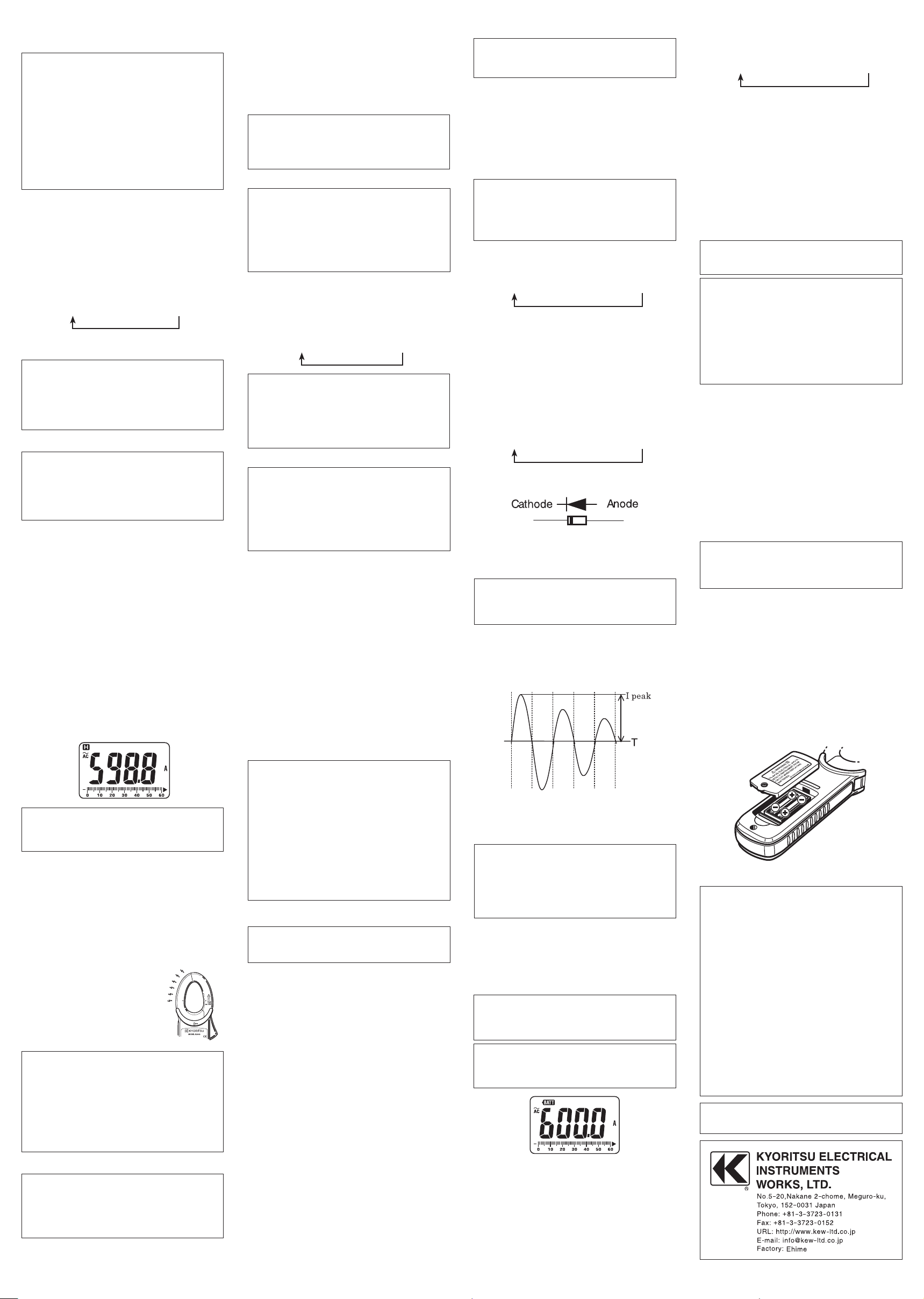
7. Battery Replacement
# WARNING
●
To avoid electrical hazard, set the Function Switch
to " OFF" a nd re mov e the tes t lea ds from the
instrument before trying to replace batteries.
# CAUTION
●
Do not mix old and new batteries.
●
Install batteries in correct polarity as indicated in
the Battery Compartment.
Replace the batteries when a Low Battery Vol tage
warn ing "BAT T" m ark is in dicat ed o n the displ ay.
Note that when the battery is completely exhausted,
the display blanks without "BATT" mark shown.
(1) Set the Function Switch to "OFF" position.
(2) Unscrew and remove the Battery Comp ar tment
Cover on the bottom of the instrument.
(3) Replace the batteries observing correct polarity.
Use new R03 (AAA)
or LR03 / 1.5V batteries.
(4) Install the Battery Compartment and tighten the
screws.
8. Maintenance
●
Cleaning
Use a cloth dipped in water or neutral detergent for
cleaning the instrument.
Do not use ab r asiv e s or s o lven t s. Other w ise,
instrument get damaged, deformed or discolored.
DISTRIBUTOR
6-10 92-1803B
 Loading...