

Page 1
2. Features
● This is a Phase indicator and can indicate a presence of live
line and phase sequence with the equipped LED and Buzzer
while clipping the 3-phase line over the jacket of a conductor.
● Brightness switch is equipped to make the indication visible
in dimly lit areas.
● A m ag net on t he b ac k si d e of th e ins tr u men t can fix the
instrument onto the distribution board and enables safety and
easy measurements.
● Designed to International safety standard IEC 61010-1 (CAT.
III 1000V/ CAT.IV, 600V, Pollution degree 2)
3. Instrument layout
● Put insul ate d p rot ec tive g ears when t here is a danger of
electrical shock hazard.
● The tip of cl ip is mad e of met al and it is not c omple te ly
insulated. Be especially careful about the possible shorting
where the measured object has exposed metal parts.
● Never attempt to use the instrument if it 's surface or your
hand is wet.
Other wise, electr ical shock accident may occur.
● Nev e r o p e n the Ba t t e r y c ompar t m e nt co v e r an d th e
instrument case when making a measurement.
● The instrument is to be used only in its intended applications
or conditions. Otherwise, safety func tions equipped with the
instrument doesn’t wor k, and instrument damage or serious
personal injur y may be caused.
● Only the q ua li fie d p er son can u se the inst ru ment at the
secondary side of high voltage power receiving equipments.
#
WARNI NG
● Never attempt to make any measurement, if any abnormal
con ditions are not ed, such as broken case, and expos ed
metal par ts.
●
Do not install substitute parts or m ake any mod if ication to the
instrument. Return the instrument to your local Kyoritsu distributor
for repair or re- calibration in case of suspected faulty operation.
● Always keep your fingers and hands behind the bar rier on
the instr ument to avoid the possible shock hazard.
● Do no t tr y to re p l a c e ba t ter i e s if th e su r fa c e o f th e
instrument is wet.
Disconnec t the clip s f rom the measu re d c on ductors f ir st
and power of f the in strumen t befo re opening the B at tery
compar tment cover for a batter y replacement.
#
CAUTION
● Do not apply shocks, vibrations or excessive forces onto the
Measurement clips.
● Never force to open the Measurement clips when they are
frozen.
● This instrument can be operated with safe at temperatures
between -10ºC and 50ºC and altitude up to 2000m.
● Keep away from dust and water.
● Precise measurement cannot be made near a charged body
or equipment generating electromagnetic waves.
● Me as ura ble con duc to r size is b et w ee n dia. 2.4 mm and
30mm. Ac cur ate measurements for co nductor s out of this
range cannot be made.
● Measured results are influenced by voltage wires on which
twice or more of the measured voltages exist near the point
to be clipped.
The clip point should be far from such voltage wires.
●
This instrument cannot identif y wir ing status correctly when an
earth line is connected bet ween phases via delta connection.
Check the connection specif ication of the measured object.
● Incapable of measuring bus bars or shielded wires. Clip onto
a covered conductor and make a measurement.
●
All the clips should be clipped onto the covered wires and
make measurements. Other wise, it may cause a malfunc tion.
1. Safety Warnings
This instrument has been designed, manufactured and tested
acco rding to follow in g sta nd ar ds an d d el iver ed in the best
condition after passing qualit y control tests.
● IE C 61010 -1 Meas u rem e n t CAT.II I 10 0 0V/ CAT.IV 6 0 0V
Pollution degree 2
● IEC61010- 031
This instruction manual contains warnings and safety rules which
have to be observed by the user to ensure safe operation of the
instrument and to maintain it in safe condit ion. Therefore, read
through these operating instructions before using the instrument.
#
WARNI NG
● Read through and understand instructions contained in this
manual before using the instrument.
●
Keep the manual at hand to enable quick reference whenever
necessary.
●
The instr ument is to be used only in its intended applications.
● Understand and follow all the safety instructions contained
in the manual.
It is es senti al tha t t he above inst ruc tio ns are adhe red to.
Failure to follow the above instructions may cause injur y and
or instrument damage.
The symbol # in dicated on th e inst ru me nt, me ans that the
user must refer to th e r el at ed par ts in the manu al for safe
operation of the instrument.
It is e ss ential to r ea d the instr uction s w herev er the sy mb ol
appears in the manual.
#
DANGER is reser ved for conditions and actions that are
likely to cause serious or fatal injur y.
#
W A R N I N G is reserved for conditions and actions that can
cause serious or fatal Injury.
#
C A U T I O N is reserved for conditions and actions that can
cause minor injur y or instrument damage.
#
DANGER
● Confir m a proper op era tio n of the instr ument with a wellknown power supply.
● Warning LED might not light up at live status. (ear th potential
70V or less). Never touch the wire.
● Voltages may exist when the Live LED is flashing (indicating
Earth phase). Never touch with the wires.
● Never ma ke measurement on a c ircuit in which the earth
potential exceeds 1000V to avoid electrical shocks.
● Do not make measurement when thunder is rumbling. If the
instrument is in use, stop the measurement immediately and
remove the instrument from the measured object.
● Do not attempt to make measuremen t in the pres enc e of
flammab le gass es. Other wi se, the use of the instrume nt
may cause sparking, which c an lead to an explosion.
● Keep you r f i ng ers and han ds beh ind the bar rie r on th e
instrument to avoid the possible shock hazard.
● Do not touch the Clips during measurements to get accurate
results.
● This instrument c annot find the missing line of the earth line.
●
Do not pull the cable when removing the Measurement clips
from the measured conductors. It may cause a break in cable.
● Power of f t he instru ment af ter use. Re move the batte ries
if the instrument is to be stored and will not be in use for a
long period.
● Do n ot e xpo s e the inst r ume n t to d ir e c t sun lig ht, h igh temperature and humidity or dew.
● Dry and store the instrument if it is wet.
● Do not ste p on or pinch th e c ord to prevent the jacket of
cable from being damaged.
● Bending or pulling the cord may cause a break in a cord.
● Neve r give shocks, such as vibratio n or dr op, which may
damage the instrument.
● Use a damp cloth and detergent for cleaning the instr ument.
Do not use abrasives or solvents.
Safety Symbols
#
Refe r to th e instructi ons in the manual to pr ote ct the
user and instrument.
Indicates instrument with double or reinforced insulation
AC
This instrument satisfies the marking requirement defined
in the W EEE Directive. This symbol indic ates separate
collection for electrical and electronic equipment.
○ Measurement categories(Over-voltage categories)
To en su re safe ope ra tio n o f m ea su rin g i ns tru me nt s, IEC 61010
establishes safety standards for various electrical environments,
categorized as CAT I to CAT IV, and called measurement categories.
Hi g h e r- n u m b e r e d ca t e g o r ie s co r r e s p o nd to el e c t r ic a l
environments with greater momentary energy, so a measur ing
inst rum ent desig ne d for C AT I II envir onm en ts c an end ur e
greater momentar y energy than one designed for CATII.
CAT I :
Secondary electrical circuits connected to an AC
electrical outlet through a transformer or similar device.
CAT II : Primar y electrical circuits of equipment connected to
an AC electrical outlet by a power cord.
CAT III : P r i m ar y el e ct ri c al ci rc u it s of th e eq u ip m en t
co n ne c te d dir ect l y to the dis t rib uti on p ane l, a nd
feeders from the distribution panel to outlets.
CAT IV : Th e cir c uit f r om t h e ser v i c e dro p to t h e ser v i c e
en t r a n c e , an d to th e po w er meter and prima r y
overcurrent protection device (distribution panel).
4. Specification
Model KEW8035
Measurement
principle
Static induction
Voltage range
3-phase AC70 to 100 0V
(voltage to earth, continuous sine wave)
Frequency range
45 to 66Hz
Operating
temperature &
humidit y range
-10 to 50ºC, relative humidity 8 0% or less
(no condensation)
Storage
temperature &
humidit y range
-20 to 60ºC, relative humidity 80% or less
(no condensation) (*1)
Location for use
Altitude 2000m or less, Indoor use
Applic able
standards
IEC 61010-1
Measurement CAT.III 1000V/CAT.IV 600V
Pollution degree 2
IEC61010 - 031
IEC 61326-1,2-2 (EMC standard)
IEC 61557-1,7
Dust-proof IP40 (IEC60529
)
Withstand
voltage
AC688 0V (rms 50/60Hz) for 5 sec
between the tip of Measurement clip and enclosure
Insulation
resistance
10MΩ or more/ 1000V
between the tip of Measurement clip and enclosure
Power source
DC6V
(size AA alkaline battery LR6 or equivalent
1.5V AA × 4pcs)
Auto-power-of f 10 min after powering on the instrument
Low battery
warning
Power LED flashes at 4.0±0.2V or less (*2)
Current
consumption
15mA (*3)
Continuous use
approx 20 0 hours (*4)
Conductor size
Exter nal diameter of the covered conductor
Dia.2.4 to 30mm
Cable length approx 70 cm
Dimension 112(L) × 61(W) × 36(D)mm
Weight approx 38 0g (
batteries included
)
Accessories
Instruction manual, bat tery, Soft case, Label for Clip
(*1) without batteries
(*2) powers off automatically at 3±0.2V or less
(*3) stand-by state (will be doubled (max) at measurement)
(*4) stand-by state (will be 0.5 times at measurement)
5. Checks and Indications
5.1. Preliminary c hecks
5.1.1. Press the Power switch and powe r on the instrument.
Then all the LEDs flash in order for about 1 sec. Confirm
all the LEDs l ig ht up and flash. Only the Power LED
keeps lighted up in about 1 sec later.
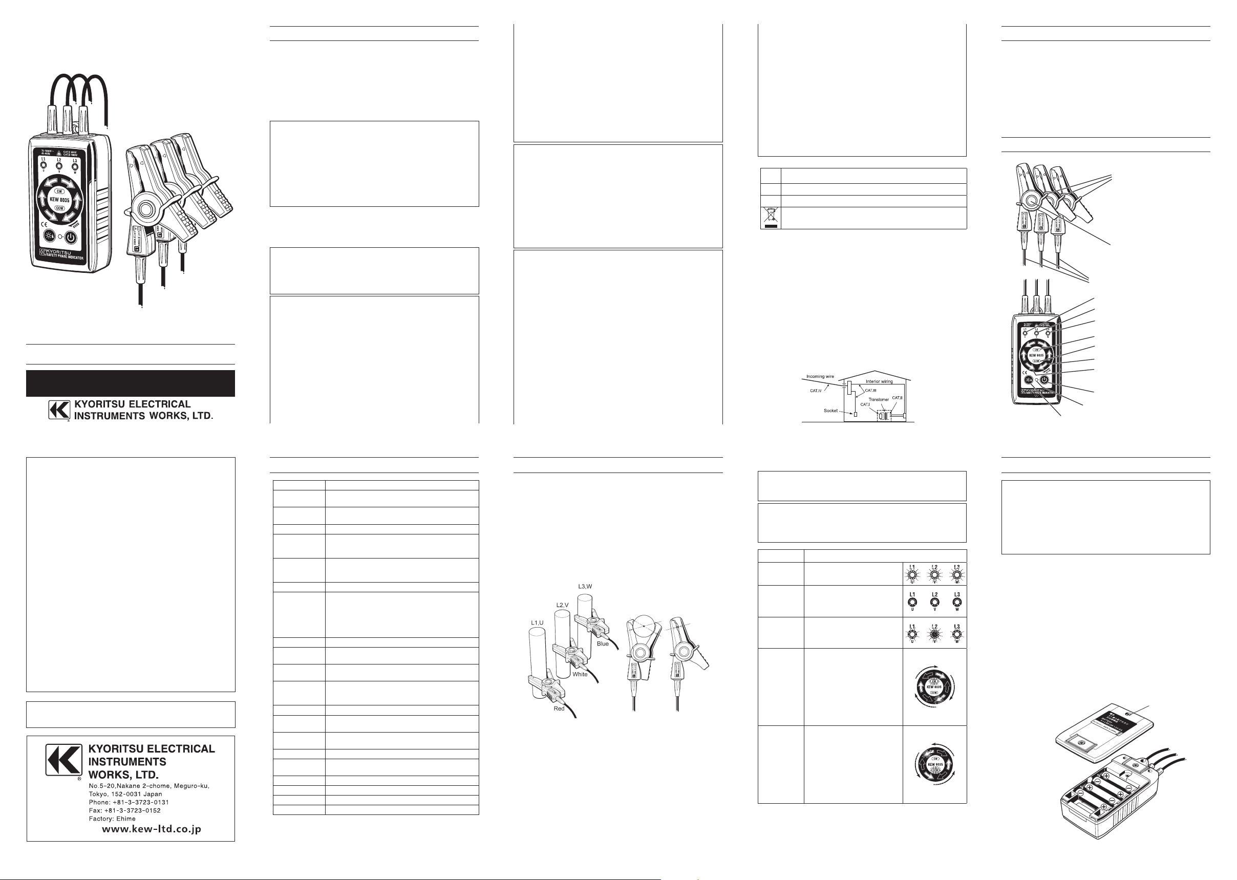
5.1.2. Ap e x of “▼” ma r k on th e Me a s u reme n t cl i p sh a l l
indicate the center of the measured conductor. Connect
ea ch M eas ur e me nt c lip to 3 - p ha se l in e as f ol l ow s:
Red to L1, Phase -U, White to L2, Phase-V, Blue to L3,
Phase -W.
5.1.3. Meas ur e a c o ve red cond uc t or AC70V or m ore firs t
to conf irm e ac h liv e LED lig ht s up. Do n ot u se t he
instrument when any of the LED doesn’t light up.
5.1.4. Pr e s e n c e of live wi r e s an d phase se q u e n c e ar e
informed by LED indication and Buzzer sound as soon
as connecting the clips.
5.2. Live wire check
#
DANGER
● LEDs don’t light up when voltage to earth is 70V or less.
● Voltages may exist at Ear th phase.
#
CAUTION
● It is impossible to detect the missing phase of the earth line.
Earth line and phase sequence are indicated if the earth line
has a missing phase.
State Indication
Live
Phase with flashing LED is
live state.
Missing line
or
Earth line
LED doesn’t light up for
missing line or ear th line.
Earth line
(Delta
connection
)
Phase with flashing LED is
an earth phase.
Positive
phase
When the green Rotation
LED flashes in the order of
the direc tion indicated by
the arrow mark (clockwise),
the circuit under test has a
positive phase.
The buzzer sounds
intermittently. (pi-pi-pi
)
Reversed
phase
When the red Rotation
LED flashes in the order
of the direction indicated
by the arrow mark
(counterclockwise), the
circuit under test has a
reversed phase. The buzzer
sounds continuously. (pi- --)
5.3. Use the B right ne ss switc h to make the LED i nd ic ati on
brighter.
Brightness of all the LEDs (except for the Power LED) is
increased while pressing down the switch.
6. Battery Replacement
#
CAUTION
● Power off the instrument and remove the Measurement clips
from the measured object when replacing batteries to avoid
electrical shocks.
● Do not mix old and new bat teries.
● Inst all batteries in co rrect polar it y as indic ate d in side the
case.
●
Use the same model of batteries from the same manufacturer.
Whe n t he Power LED on th e f ront s ide of the i nstrume nt is
flash ing, b at ter y volta ge is low. Replace batt eries wi th new
ones to continue further measurements.
Low bat tery voltage may not affect measurement accuracies.
The instrument is powered off automatically when bat teries are
exhausted.
1) Loosen the screw fixing the Battery compartment cover.
2) Slide the Battery compartment cover downwards to remove
it.
3) Rep la ce the batteri es with new ones . Fou r s ize A A LR6
alka li ne or equival en t 1.5 V A A t yp e batt eri es shoul d b e
used.
4) Install the Batter y compartment cover and tighten the screw.
Instruction Manual
Non-Contact Safety Phase Indicator
KEW 8035
09-01 92-2009
Barrie
Measurement clip
Test leads
Live LED (L1, Phase-U)
Live LED (L2, Phase-V)
Live LED (L3, Phase-W)
Phase sequence LED (positive)
Phase sequence LED (reversed)
Rotation LED (positive)
Rotation LED (reversed)
Power switch
Power LED
Brightness switch
Put the Label for clip,
if necessary.
Lines c onnec ting the apexes
of “▼” m ar ks sh oul d pas s
through the center of the
conductor.
Screw
Batter y com part ment
cover
DISTRIBUTOR
Kyoritsu reserves the rights to change specifications or designs
described in this manual without notice and without obligations.
 Loading...