

Page 1
CAUTION
●
Do not expose the instrument to the direct sun, extreme temperatures or dew
fall.
○Following symbols are used on the instrument and in the instruction manual.
Attention should be paid to each symbol to ensure your safety.
Refer to the instructions in the manual.
This symbol is marked where the user must refer to the instruction manual
so as not to cause personal injury or instrument damage.
Indicates an instrument with double or reinforced insulation.
Indicates that this instrument can clamp on bare conductors when measuring
a voltage corresponding to the applicable Measurement category, which is
marked next to this symbol.
Indicates AC (Alternating Current).
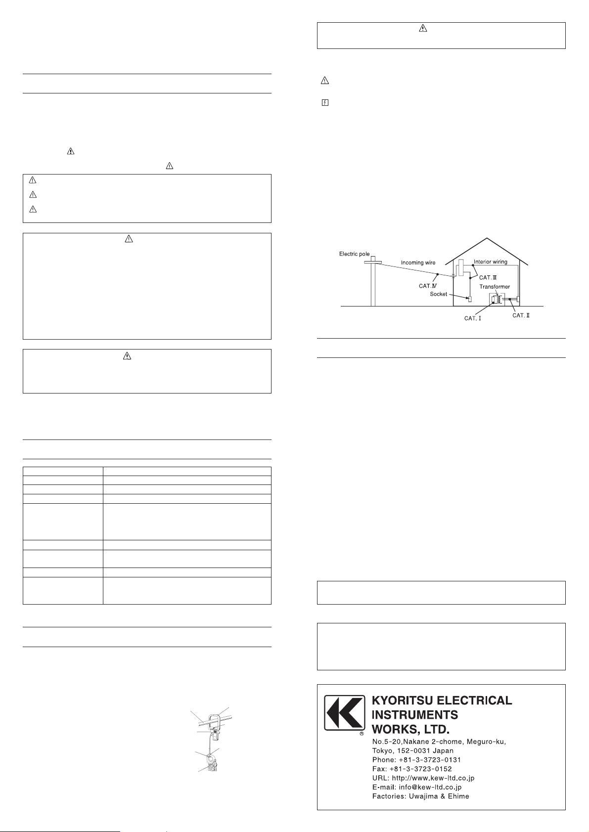
○Working voltage is specified according to each Measurement category, which is
defined in safety standards. It is to protect the user from transient impulse,
which presents in the circuit under test. Measurement categories are defined as
follows.
CAT.Ⅰ: Secondary electrical circuits connected to an AC electrical outlet
through a transformer or similar device.
CAT.Ⅱ: Primary electrical circuits of equipment connected to an AC electrical
outlet by a power cord.
CAT.Ⅲ: Primary electrical circuits of the equipment connected directly to the
distribution panel, and feeders from the distribution panel to outlets.
CAT.Ⅳ: The circuit from the service drop to the service entrance, and to the
power meter and primary over-current protection device (distribution
panel).
2.FEATURES
MODEL 8008 are designed to increase the measuring capability of your clamp
meters. With the use of the MULTI-TRAN, you can not only extend current
ranges, but clamp on a conductor of a larger diameter.
INSTRUCTIONMANUAL
MULTI-TRAN
MODEL8008
1.SafetyWarnings
●
This instrument has been designed and tested to CAT.Ⅲ 300V/CAT.Ⅱ 600V
and pollution degree 2 specified by the international safety standard IEC
61010.
This instruction manual contains warnings and safety rules which must be
observed by the user to ensure safe operation of the instrument and retain it in
safe condition. Therefore, read through these operating instructions before
using the instrument.
●
The symbol indicated on the instrument means that the user must refer to
related parts in the manual for safe operation of the instrument. Be sure to
carefully read the instructions following each symbol in this manual.
DANGER is reserved for conditions and actions that are likely to cause
serious or fatal injury.
WARNING is reserved for conditions and actions that can cause serious or
fatal injury.
CAUTION is reserved for conditions and actions that can cause minor injury
or instrument damage.
DANGER
●
Never make measurement on a circuit above 600V AC.
●
Do not attempt to make measurement in the presence of flammable gasses,
fumes, vapor or dust.
Otherwise, the use of the instrument may cause sparking, which can lead to
an explosion.
●
Transformer jaw tips are designed not to short the circuit under test. If
equipment under test has exposed conductive parts, however,extra
precaution should be taken to minimize the possibility of shorting.
●
Never attempt to use the instrument if its surface or your hand is wet.
●
Do not exceed the maximum allowable input of any measurement range.
●
As to current measurement of more than 1000A, do not make measurement
continuously.
The main unit is heated, so there is danger which damages safety.
WARNING
●
Never attempt to make any measurement if any abnormal conditions are
noted, such as broken case, cracked test leads and exposed metal parts.
●
Do not install substitute parts of make any modification to the instrument.
Return the instrument to your distributor for repair or re-calibration.
Measuring Range
Input / Output
Accuracy
Withstand Voltage
Dimensions
Weight
Conductor Size
Frequency
Duty Cycle
0-3000A AC
10:1
±2% of input ±0.5A
3700V AC for one minute
MULTI-TRAN except Pick-up coil
317(L)×150(W)×30(D)mm
Pick-up coil
40(L)×45(W)×10(D)mm
Approx. 750 g
100mm max. diameter
100×150mm Bus-Bar
50Hz / 60Hz
Continuous for 0-1000A
10 minutes for 1000-1500A
30 seconds for 1500-3000A
4.HOWTOUSE
(1) Clamp your clamp meter on the pick-up coil of the MULTI-TRAN. Then clamp
the MULTI-TRAN on the conductor as shown bellow.
Multiply the reading of your clamp meter by ten.
(2) When you use MULTI-TRAN for power or power factor measurement;
・Clamp your clamp meter on the
pick-up coil of the MULTI-TRAN,
assuming that the arrow mark on
the pick-up coil points the load
side.
・Then clamp the MULTI-TRAN on
the conductor so that the arrow
mark on the MULTI-TRAN jaw
points the load side of the
conductor.
Transformer Jaws
Arrow Mark
Pick-up Coil
Conductor
Multi-Tran
Arrow Mark
Clamp Meter
Kyoritsu reserves the rights to change specifications or designs described in
this manual without notice and without obligations.
DISTRIBUTOR
3.SPECIFICATIONS
F
〜
 Loading...