

Page 1
INSTRUCTION MANUAL
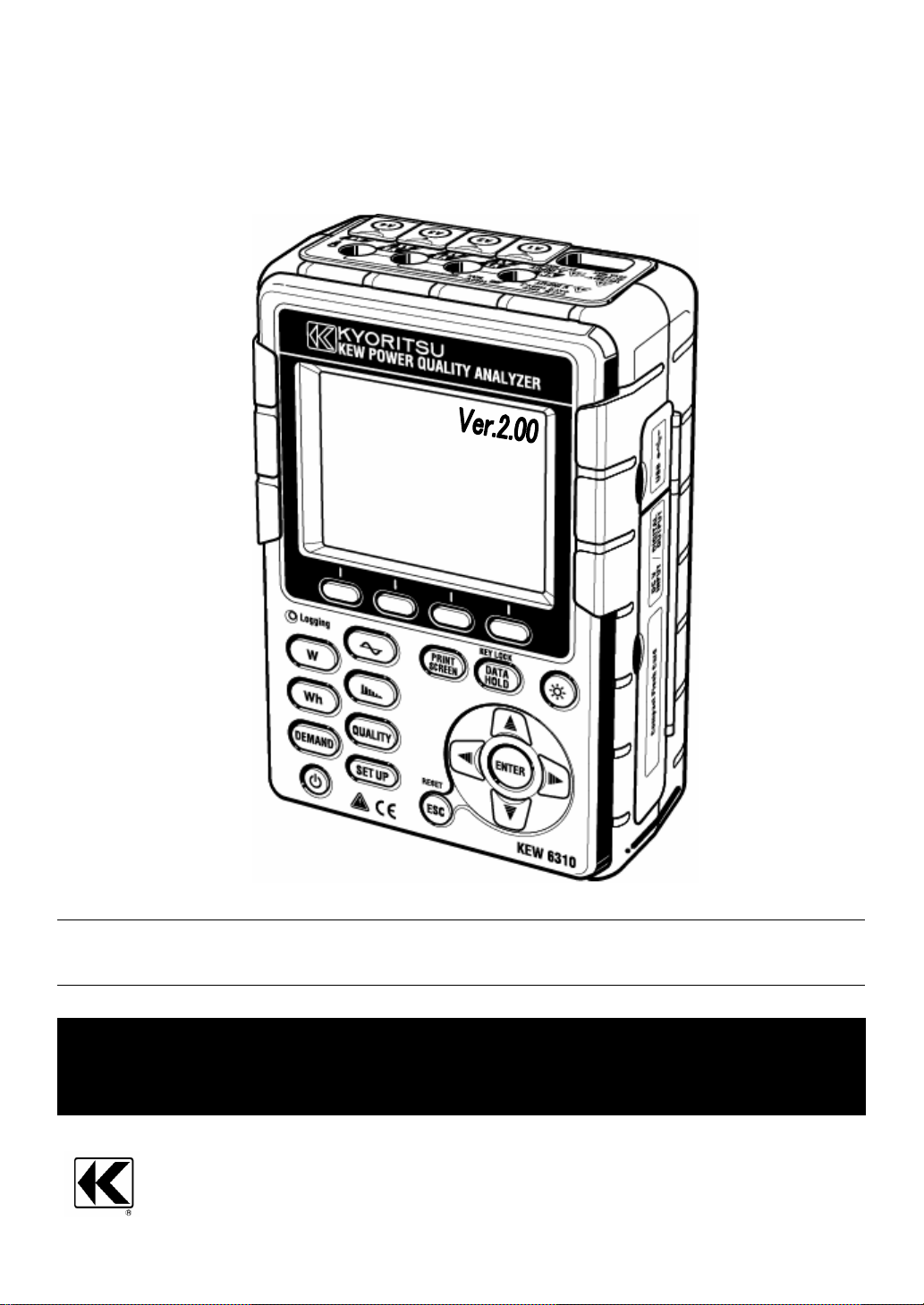
POWER QUALITY ANALYZER
KEW 6310
KYORITSU ELECTRICAL INSTRUMENTS WORKS, LTD.
TOKYO, JAPAN
Page 2

Contents KEW6310
Contents ········································································································································1
Unpacki ng·······································································································································5
Safety warnings······························································································································7
Section 1 Instrument Overvie w···································································································· 1.1
1.1 Functional Overview······························································································· 1.1
1.2 Features·················································································································· 1.3
1.3 Connection Diagram······························································································ 1.5
1.4 Measuring Procedure····························································································· 1.6
1.5 Outline of max demand me asurem ent con cept··················································· 1.7
Section 2 Instrument Layout········································································································· 2.1
2.1 Front View··············································································································· 2.1
2.2 Connector················································································································ 2.3
2.3 Side Face················································································································2.4
2.4 Battery Case··········································································································· 2.5
2.5 Marks di splayed on the L CD··················································································2.6
Section 3 Getting st arted···············································································································3.1
3.1 Preparation·············································································································· 3.1
3.1.1 Putting Input terminal plate on the Input terminal··································································3.1
3.1.2 Attaching Markers to Voltage test leads and Clamp sensors··············································
3.2
3.2 Power Supply··········································································································3.3
3.2.1 Battery········································································································································3.3
3.2.2 AC Power Supply·····················································································································
3.9
3.3 Vol tage test leads and Clamp sensor connection···············································3.10
3.4 Start KEW6310······································································································3.11
3.4.1 S t art-up Screen··························································································3.1 1
3.4.2 Erro r messa ge··························································································3.13
Section 4 Setting···························································································································4.1
4.1 List of Setting ite ms································································································· 4.1
4.2 Settings··················································································································· ·4.3
4.2.1 Basic Setting······························································································································4.3
4.2.2 Measurement Setting············································································································
4.2.3 Save Setting···························································································································4.59
4.2.4 Other Setting··························································································································
4.21
4.75
Section 5 W iring C onfigur ations···································································································5.1
5.1 Important preliminary ch ecks··················································································5.1
5.2 Basic Wiring Confi guratio n····················································································· 5.2
5.3 Wiring check············································································································5.7
5.3.1 Checking procedure·················································································································5.7
5.3.2 Criteria of Judgment·················································································································
5.8
5.4 Using supplementary VT/CT’s ··············································································· 5.9
1 KEW6310
Page 3

KEW6310 Contents
Section 6 Instantaneous value measurement············································································· 6.1
6.1 Indications on LCD·································································································· 6.1
6.1.1 Display screen..........................................................................................................................6.1
6.1.2 Switching displays....................................................................................................................
6.1.3 Zoom..........................................................................................................................................
6.8
6.9
6.2 Measuring Procedure ····························································································6.1 1
6.3 Data saving············································································································6.12
6.3.1 Saving Inst measurement data····························································································6.12
6.3.2 Limitations of saving··············································································································
6.3.3 Saved data·····························································································································
6.14
6.15
6.4 Ranges and Over-range indications····································································6.18
6.4.1 Ranges···································································································································6.18
6.4.2 Over-range / Bar indication···································································································
6.21
Section 7 In tegrat ion mea sureme nt·····························································································7.1
7.1 Indications on LCD··································································································7.1
7.1.1 Display screen··························································································································7.1
7.1.2 Switching displays····················································································································
7.1.3 W Range display······················································································································
7.2
7.3
7.2 Measuring Procedure······························································································ 7.4
7.3 Data saving··············································································································7.5
7.3.1 Saving Integration measurement dat a···················································································7.5
7.3.2 Limitations of saving·················································································································
7.3.3 Saved data································································································································
7.7
7.7
7.4 Ranges and Over-range indications ······································································ 7.9
7.4.1 Ranges······································································································································7.9
7.4.2 Over-range / Bar indication······································································································
7.9
Section 8 D emand me asure ment································································································8.1
8.1 Indications on LCD·································································································· 8.1
8.1.1 Display screen··························································································································8.1
8.1.2 Switching displays····················································································································
8.1.3 W Range / Wh Range display ································································································
8.5
8.5
8.2 Measuring Procedure ····························································································· 8.6
8.3 Data saving·············································································································· 8.7
8.3.1 Saving Demand measurement data······················································································8.8
8.3.2 Limitations of saving··············································································································
8.3.3 Saved data·····························································································································
8.10
8.10
8.4 Ranges and Over-range indications····································································8.12
8.4.1 Ranges···································································································································8.12
8.4.2 Over-range / Bar indication···································································································
8.12
Section 9 WA VE R ange················································································································9.1
9.1 Indications on LCD·································································································· 9.1
9.1.1 Display screen··························································································································9.1
9.1.2 Switching displays····················································································································
9.1.3 Zooming/ downsizing ·············································································································
9.3
9.5
9.2 Measuring Procedure ····························································································· 9.6
KEW6310 2
Page 4

Contents KEW6310
9.3 Data saving·············································································································· 9.7
9.3.1 Saving Procedure·····················································································································9.7
9.3.2 Limitations of saving·················································································································
9.3.3 Saved data································································································································
9.9
9.9
9.4 Ranges and Over-range indications····································································9.12
9.4.1 Ranges···································································································································9.12
9.4.2 Over-range / Bar indication···································································································
9.12
Section 10 Ha rmonic Analy sis···································································································· 10.1
10.1 Indications on LCD····························································································· 10.1
10.1.1 Display screen·······················································································································10.1
10.1.2 Switching displays·················································································································
10.1.3 Logarithm display··················································································································
10.4
10.5
10.2 Measuring Procedure·························································································10.6
10.3 Data saving·········································································································10.7
10.3.1 Saving Procedure··················································································································10.7
10.3.2 Limitations of saving··············································································································
10.3.3 Saved data·····························································································································
10.9
10.9
Section 1 1 P ower Qual ity·············································································································1 1.1
11.1 Display screen·····································································································1 1.2
11.2 Swell / Dip / Int mea sureme nt·············································································1 1.3
11.2.1 Display screen··················································································································11.3
11.2.2 Measuring Procedure······································································································
11.2.3 Data saving·······················································································································
11.2.4 Limitations of saving·········································································································
11.2.5 Saved data························································································································
11.4
11.7
11.9
11.9
11.3 Transient measureme nt····················································································11.1 1
11.3.1 Display screen················································································································11.11
11.3.2 Measuring Procedure····································································································
11.3.3 Data saving·····················································································································
11.3.4 Limitations of saving·······································································································
11.3.5 Saved data·····················································································································
11.12
11.14
11.16
11.16
11.4 Inrush current measurement············································································11.1 9
11.4.1 Display screen················································································································11.19
11.4.2 Measuring Procedure····································································································
11.4.3 Data saving·····················································································································
11.4.4 Limitations of saving·······································································································
11.4.5 Saved data·····················································································································
11.20
11.22
11.24
11.24
11.5 Unbalance rate measurement·········································································11.27
11.5.1 Display screen······················································································· 1 1.27
11.5.2 Measuring Procedure···································································································
11.5.3 Data saving····················································································································
11.5.4 Limitations of saving······································································································11.31
11.5.5 Saved data·····················································································································
11.28
11.29
11.31
3 KEW6310
Page 5

KEW6310 Contents
11.6 Flicker······················································································································1 1.33
11.6.1 Display screen·····················································································································11.33
11.6.2 Measuring Procedure·········································································································
11.6.3 Data saving··························································································································
11.6.4 Limitations of saving············································································································
11.6.5 Saved data···························································································································
11.37
11.38
11.40
11.40
11.7 Capacitance Calculation- Sizing of capacitor banks for Power factor correction
(PFC) ·································································································································1 1.43
11.7.1 Display screen·····················································································································11.43
11.7.2 Measuring Procedure·········································································································
11.7.3 Data saving··························································································································
11.7.4 Limitations of saving············································································································
11.7.5 Saved data···························································································································
11.45
11.46
11.48
11.48
Section 12 CF card/ Internal memory····························································································· 12.1
12.1 Instrument and CF card / Internal memory·························································· 12.1
12.2 Placing / removing the CF card············································································· 12.4
12.3 CF card and Internal memory················································································ 12.6
12.4 Backup memory······································································································12.9
Section 13 Communication function/ Interface software······························································ 13.1
13.1 Software Installation (KEW PQA MA STER)························································ 13.2
13.2 USB driver installation····························································································· 13.4
13.3 Starting “KEW PQA MASTER”·············································································· 13.6
13.4 USB driver un-installation······················································································· 13.7
Section 14 Other functions··············································································································· 14.1
14.1 Input/ Output terminals···························································································· 14.1
14.2 Getting power from measured lines······································································ 14.2
14.3 Auto-ranging············································································································ 14.4
14.4 Operation at AC power interruption·······································································14.4
Section 15 Troubleshooting·············································································································15.1
15.1 General troubleshooting························································································· 15.1
15.2 Error messages and actions··················································································15.2
Section 16 Specification··················································································································· 16.1
16.1 General specification······························································································ 16.1
16.2 Inst measurement··································································································· 16.2
16.3 Integration measurement······················································································· 16.4
16.4 Demand measurement·························································································· 16.6
16.5 Waveform measurement ······················································································· 16.6
16.6 Harmonic measurement························································································ 16.6
16.7 Power quality··········································································································· 16.7
16.7.1 Swell/ Dip/ Int measurement································································································16.7
16.7.2 Transient measurement········································································································
16.7.3 Inrush current measurement································································································
16.7.4 Unbalance rate measurement·····························································································
16.7.5 Capacitance calculation········································································································
16.7
16.7
16.7
16.8
16.8 Other specifications································································································· 16.8
16.9 Specification of Clamp sensor ·············································································16.11
KEW6310 4
Page 6
Unpacking Procedure KEW6310
● Unpacking Procedure
We thank you for purchasing the
instrument before use.
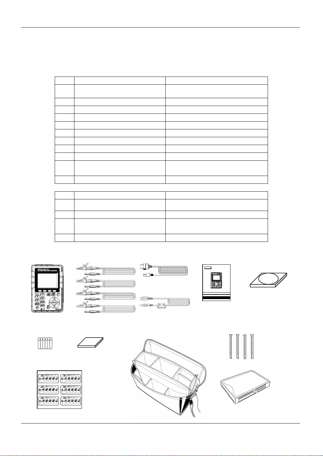
● Items listed below are included with the standard set:
Main unit
1
Voltage test lead
2
Power cord
3
USB cord
4
Quick manual
5
CD-ROM
6
Battery
7
8 Compact flash card 1 pce
9 Carrying case MODEL9125 : 1 pce
10 Input terminal plate 1 pce
11 Cable marker
12 Card Reader MODEL8319
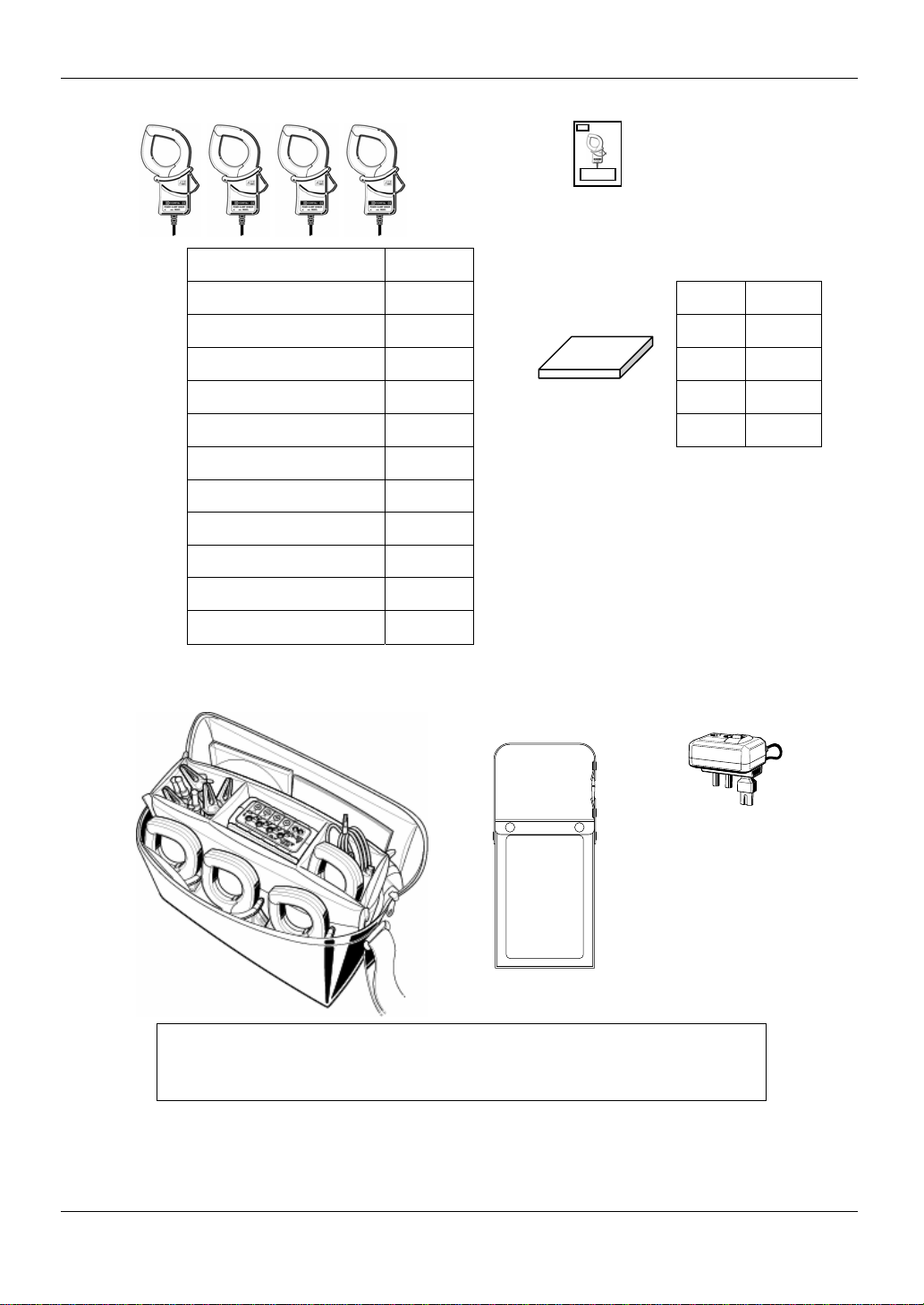
Optional parts
Clamp sensor
13
Instruction manual for
14
clamp sensor
15 Compact fla sh ca rd 64M/ 128M/ 256M/ 1GB
Carrying case for Main unit
16
(with magnet)
17 Power supply adap te r MODEL8312
1. Main unit 2. Voltage test lead 3. Power cord 5. Quick manual 6. CD-ROM
Power Quality Analyzer “KEW6310”. Please check the contents and
KEW6310 : 1 unit
MODEL7141 : 1 set
(red, black, green, blue: 1pce for each)
MODEL7170 : 1 pce
MODEL7148 : 1 pce
1 pce
1 pce
Alkaline size AA battery LR6: 6pcs
8-color x 4pcs each (red, blue, yellow,
green, brown, gray, black, white)
Depending on model pu rch ased
1 pce
MODEL9132
4. USB cord
7. Battery 8. Compact flash card 9. Carrying case 11. Cable marker
10. Input terminal plate 12. Card Reader : M-8319
5 KEW6310
Page 7
KEW6310 Unpacking Procedure
13. Clamp sensor 14. Instruction manual for clamp sensor
(depending on model purchased )
50A T ype(φ24mm) M-8128
100A T y pe(φ24mm) M-8127
200A T y pe(φ40mm) M-8126
500A T y pe(φ40mm) M-8125
1000A T y pe(φ68mm) M-8124
3000A T y pe(φ150mm) M-8129
10A T ype(φ24mm) M-8146
10A T ype(φ40mm) M-8147
10A T ype(φ68mm) M-8148
1A T ype (φ24mm) M-8141
1A T ype (φ40mm) M-8142
1A T ype (φ68mm) M-8143
15. Compact flash card
32MB M-8305
64MB M-8306
128MB M-8307
256MB M-8322
1GB M-8323
● Storage
Store the items as shown below after use. 16. Carrying case for Main unit 17. Power supply adapte r
(with magnet)
● In case any of the items listed above are found to be damaged or missing or if the
printing is unclear, please contact your local KYORITSU distributor from where the
instrument was purchased.
KEW6310 6
Page 8
Safety warnings KEW6310
● Safety warnings
This instrument has been designed, manufactured and tested according to IEC 61010: Safety requirements
for Electronic Measuring apparatus, and delivered in the best condition after passing quality control tests.
This instruction manual contains warnings and safety rules which have to be observ ed by the user
to ensure safe operation of the instrument and to maintain it in sa fe con dition. Therefo re, rea d through
these operating instructions before using the instrument.
WARNING
● Read through and understand the instructions contained in this manual before using the instrument.
● Keep the manual at hand to enable qui ck referen ce w heneve r ne cessa ry.
● The instrument is to be used only in its intended applications.
● Understand and follow all the safety instructions contained in the manual.
● Read the enclosed Quick manual after reading this instruction manual.
● As to the Clamp sensor use, refer to the instruction manual supplied with the sensor.
It is essential that the above instructions are adhered to. Failure to follow the above instructions may cause
injury, instrument damage and/or damage to equipment under test.
The symbol indicated on the instrument, means that the user must refer to the related parts in the manual
for safe operation of the instrument. It is essential to read the instructions wherever the symbol appears in
the manual.
is reserved for conditions and actions that are likely to cause
DANGER
WARNING
CAUTION
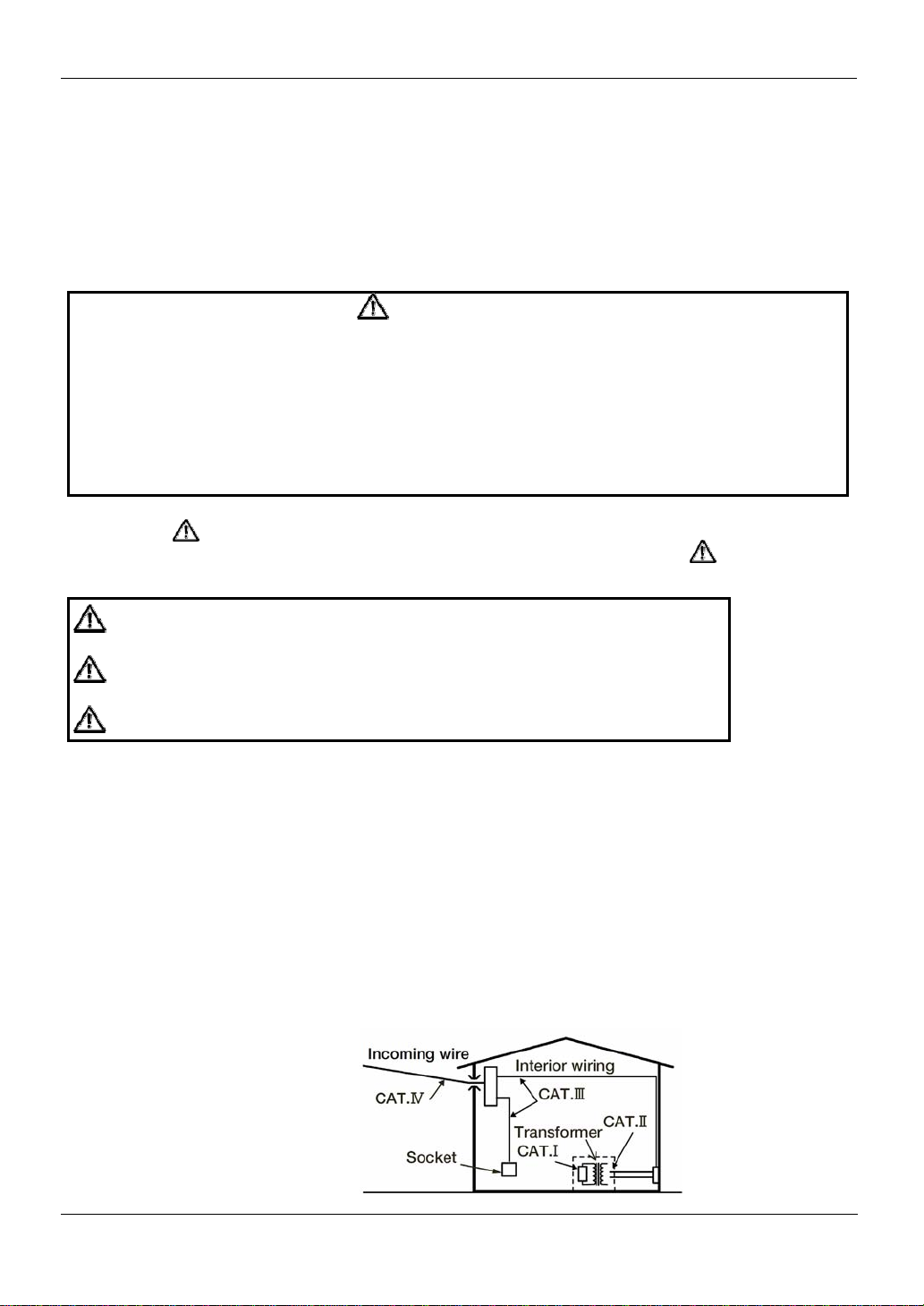
This instrument meets CAT. III 600V. To ensure safe operation of measuring instruments, IEC 61010 establishes
safety standards for various electrical environments, categorized as CAT.I to CAT.IV, and called measurement
categories. Higher-numbered catego ries correspon d to el ec tric al en vi ron men ts with grea ter mo mentary en ergy ,
so a measuring instrument designed for CAT.III environments can endure greater momentary energy than one
designed for CAT.II.
CAT.I: Secondary electrical circuits connected to an AC electrical outlet through a transformer or similar device.
CAT.II: Primary electrical circuits of equipment connected to an AC electrical outlet by a power cord.
CAT.III: Primary electrical circuits of the equipment connected directly to the distribution panel, and feeders from
the distribution panel to outlets.
CAT.IV: The circuit from the service drop to the service entrance, and to the power meter and primary overcurrent
protection device (distribution panel).
:
serious or fatal injury.
is reserved for conditions and actions that can cause serious or
:
fatal injury.
is reserved for conditions and actions that can cause injury or
:
instrument damage.
7 KEW6310
Page 9

KEW6310 Safety warnings
DANGER
● Ve rify prop er opera tio n on a kn ow n source be fore use.
● Verify proper operation on a known source before use or taking action as a result of the indication of the
instrument.
● Never make measurement on a circuit in which the electrical potential exceeds AC600V.
● Do not attempt to make measurement in the presence of flammable gasses. Otherwise, the use of the
instrument may cause sparking, which can lead to an explosion.
● Never attempt to use the instrument if its surface or your hand are wet.
- Measurement -
● Do not exceed the maximum allowable input of any measuring range.
● Never open the Battery cover and CF card connector cover during a measurement.
- Battery -
● Never open the Battery Cover during a measurement.
● Brand and type of the batteries to be used should be harmonized.
- Power cord -
● Connect the Power cord mains plug to a mains socket outlet
● Use only the Power cord supplied with this instrument.
- Power supply connector -
● Never touch the Power su pply conne ctor al thou gh it is insu l ated w hile the instrumen t is opera ti ng w ith
batteries.
- Volt age te st lead s -
● Use only the ones supplied with this instrument.
● Confirm that the measured voltage rating of the test lead is not exceeded.
● Do not connect a Voltage test lead unless required for measuring the parameters desired.
● Connect V oltage test leads to the instrument first, and only then connect them to the circuit under
test.
● Never disconnect Voltage test leads while the instrument is in use.
● Connect to the downstream side of a circuit breaker since a current capacity at the upstream side is large.
● Do not touch two lines under test with the metal tips of the test leads.
● Never touch the metal tips of the test leads.
- Clamp sensor -
● Use only the ones dedicated for this instrument.
● Confirm that the measured voltage rating of the test lead is not exceeded.
● Do not connect a Camp sensor unless required for measuring the parameters desired.
● Connect sensors to the instrument first, and only then connect them to the circuit under test.
● Never disconnect sensors while the instrument is in use.
● Connect to the downstream side of a circuit breaker since a current capacity at the upstream side is large.
● Do not touch two lines under test with the metal tips of the test leads.
KEW6310 8
Page 10

Safety warnings KEW6310
WARNING
- Connection -
● Confirm that the instrument is off, and then connect the Power cord.
● Connect the Voltage test leads and clamp sensors to the instrument first. Cord to be firmly inserted.
● Never attempt to make any measurement if any abnormal conditions, such as a broken cover or
exposed metal parts are present on the Instrument, Voltage test leads, Power cord and Clamp sensor.
- Measurement –
● Ensure that the Current input terminal cover, USB connector cover and C F card c onne c tor cove r are
closed when not in use during a measuremen t.
- Not in use for a long period -
● Remove the Power co rd fro m the ou tl et if the in strume n t w ill no t be in use fo r a long pe riod .
- Repair -
● Do not install substitute parts or make any modification to the instrument. Return the instrument to your
local KYORITSU distributor for repair or re-calibration in case of suspected faulty operation.
- Battery -
● Do not try to replace the batteries if the surface of the instrument is wet.
● Ensure that the Power cord, Voltage test leads and Clamp sensor are removed from the instrument,
and that the instrument is switched off when opening the Battery cover for battery replacement.
● Do not use dry-cell batteries with the Selector Switch set to “RECHARGEABLE BA TTERY” position.
It may cause electrical shock accident.
● Never mix new and o ld batteries.
● Install batteries in correct polarity as marked inside.
- Power cord -
● Do not use the damaged cord.
● Don’t put heavy things on, step on or pin ch the cord , m oreo ver, not to touch any heating material.
● When unplugging the cord from the mains socket outlet, do so by removing the plug first and not by
pulling the Power cord .
- Measures against abnormal symptoms -
● If the instrument begins to emit smoke, becomes too hot, or gives off an unusual smell, immediately
power it off and disconne ct the pow er cord from the ou tle t. Also pow er off th e power to the object under
test. If any anomalies as noted, contact your local KYORITSU distributor.
- Use of protective gears -
● Use insulated gloves, boots or head gears at measurements to ensure user’s safety.
9 KEW6310
Page 11
KEW6310 Safety warnings
CAUTION
● Caution should be taken since conductors under test may be hot.
● Never apply currents or voltages exceeding the maximum allowable input for the instrument for a long time.
● Don’t apply currents or voltages to Voltage test leads or Clamp sensors while the instrument is in off status.
● Don’t use the instrument at dusty places or to be spattered.
● Don’t use the instrument under a strong electric storm or in the vicinity of energized object.
● Never give strong vibrations or drop shocks.
● Do not place or remove a CF card while CF card is being accessed. ( flashes while CF card is being
accessed.) Otherwise saved data in the card or the instrument may be damaged.
- Clamp sensor -
● Do not bend or pull the cable of the Cl amp se nso r.
- Treatment after use -
● Power off the instrument and disconnect the Power cord, Voltage test leads and Clamp sensors from
the instrument.
● Remove the batteries i f th e instrumen t i s to be store d and w ill no t be in use fo r a long pe riod .
● Remove the CF card w hen ca rry ing the in strumen t.
● Never give strong vibrations or drop shocks when carrying the instrument.
● Do not expose the instrument to direct sunlight, high temperatures, humidity or dew.
● Use a damp cloth with neutral detergent for cleaning the instrument. Do not use abrasives or solvents.
● Do not store the instrument if it is wet.
Carefully read and follow the instructions: DANGER, WARNING, CAUTION and NOTE ( )
described in each section.
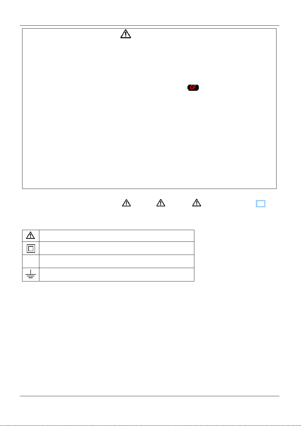
The following symbols are used in this manual:
User must refer to the explanations in the instruction manual.
Instrument with double or reinforced insulation, Class II insulation
~ AC
(Functional) Earth terminal
KEW6310 10
Page 12
1.1 Functional Overview KEW6310
1. Instrument Overview
1. 1 Functional Overview
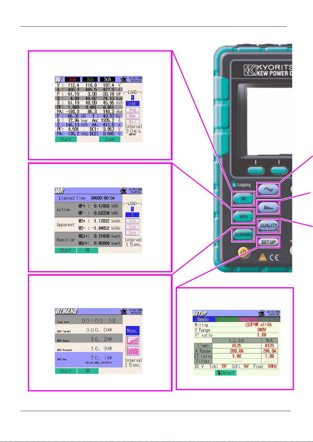
Instantaneous value measurement
Measures average/max/min values of instantaneous
values of current, voltage and electric power.
See Section 6 “Instantaneous value measureme nt”
for further details.
Integration value measurement
Measures active/ apparent/ reactive powers on
each CH.
See Section 7 “Integration value measurement”
for further details.
Demand measurement
Measures demand values based on the preset target
values. Digital output signals alert the user that the
predicted value may exceed a target value.
See Section 8 “DEMAND Measurement” for further
details.
SET UP
Setting of KEW6310 or for measurements
See “Setting (Section 4)” for further details.
1.1 KEW6310
Page 13
KEW6310 1.1 Functional Overview
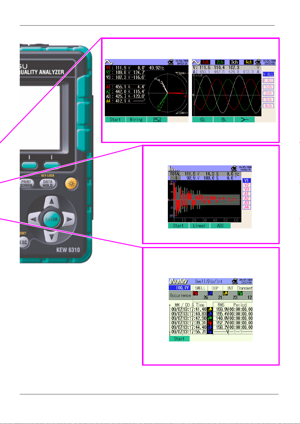
Measurement at WAVE Range
Displays vector / wave for m of vo l t age s and c u rrents per CH
See “WAVE Range (Section 9)” for further details.
Harmonic measurement
Measures / analyzes harmonic compon en t s o f cu rren t &
voltages
See “Harmonic Analysis (Section 10)” for further
Power quality analysis
Measures swell, dip, int, transient, inrush current,
unbalance ratio and flicker, and also simulates power
factor correction with capacitor banks.
* Flicker measurement function is only available with ver .2.00 or
later.
See “Power Quality (Section 11)” for further details.
KEW6310 1.2
Page 14

1.2 Features KEW6310
1.2 Features
This is a Power Quality Analyzer that can be used for various wiring systems. It can be used for
simple measurements of instantaneous/ integration/ demand values, and also for monitoring
waveforms and vectors, analyzing harmonics and measuring the fluctuations in supply voltages and
can perform Capacitance Calculation. Data can be saved either in the internal memory or a CF card,
and can be transferred to a PC either via a USB lead or a CF Card reader.
Safety Construction
Designed to meet the international safety standard IEC 61010-1 CAT.III 600V/ CATII. 1000V
Wiring configuration
KEW6310 supports : Single-phase 2-wire, Sin gle-pha se 3-w ire, Three-phase 3-wire, Three-phase 4-wire .
Measurement and caluclation
KEW6310 measures voltage (RMS), current (RMS), and calculates active/reactive/apparent power , power factor,
phase angle, frequency, neutral current and active/ reactive/ apparent electric energy. (RMS)
Demand measurment
Electricity consumption can be easily monitored so as not to exceed the target maximum demand values.
Waveform / Vector display
Voltage and current can be displayed by waveform or vector.
Harmonic analysis
Harmonic components of voltage and current can be measured and analyzed.
Power quality analysis
Measuring Swell/ Dip/ Int, Transient, Inrush current, Unbalance ratio and flicker*, moreover , simulating power
factor correction with capacitor banks.
* Flicker measurement function is only available with ver.2.00 or later.
1.3 KEW6310
Page 15

KEW6310 1.2 Features
Saving data
KEW6310 is endowed with a logging function with a preset recording interval. Data can be saved by manual
operation or at pre-set time & date. Screen data can be saved by using Print Screen function.
Dual power supply system
KEW6310 operates either with AC power supply or with batteri es. Bo th d ry -cel l batte rie s (al kal ine ) and
rechargeable batteries (Ni-MH) can be used. In the event of interruption, while operating with AC power supply,
power to the instrument is automatically restored by the batteries in the instrument.
Large display
Color display with large screen
Light & compact design
Clamp sensor type, compact and light weight design
Application
Data in the internal memory or CF card can be transferred to a PC via a USB lead or a CF Card reader. As well
supplied software fa ci litates setting, optional analysis sof tw are fa cili t a te s data analysis.
Input/output function
Analogue signals from thermometers or light sensors can be measured simultaneously with electrical power
data via 2 analogue inputs (DC voltage); signals exceeding preset threshold values at each range can be
transmitted to alarm devices via 1 digital output (DC voltage)
KEW6310 1.4
Page 16
1.3 Connection Dia gram KEW6310
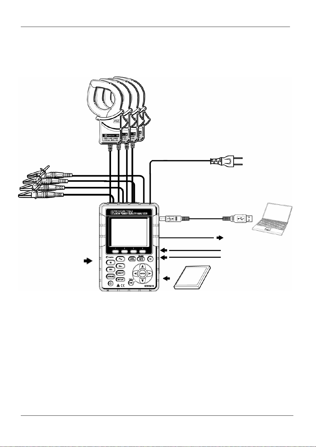
1.3 Connection Diagram
Volt age Inp ut
Current Input
Power Cord
PC
Alkaline dry-cell / Ni-MH
rechargeable batteries
Digital Output (1ch)
Analogue Input (2ch)
USB
Recorder / Alarm device
Thermometer/Light sensor
CF Card
1.5 KEW6310
Page 17
KEW6310 1.4 Measuring Procedure
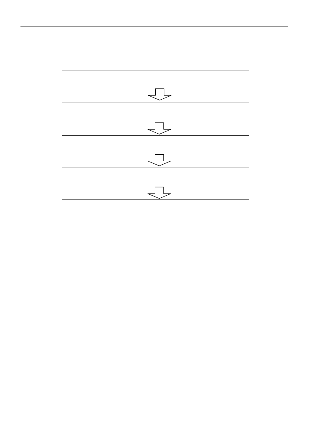
1.4 Measuring Procedure
● Step s for measurement
Ensuring your safety
See “Safety Warnings”.
Preparation
See “Section 3: Getting started”.
Basic / Measurement / Save Settings
See “Section 4: Setting”.
Wiring
See “Section 5: Wiring”.
* Measuring instantaneou s values :
“Section 6: Instantaneous value Measurement”
* Measuring integration values:
“Section 7: Integration value Measurement”
* Measuring demand valu es:
“Section 8: Demand Measurement”
* Measuring vectors and waveforms:
“Section 9: W AVE Range”
* Analyzing Harmonics:
“Section 10: Harmonic Analysis”
* Measuring Power Quality:
“Section 11: Power Quality”
KEW6310 1.6
Page 18

1.5 Outline of max demand measurement concept KEW6310
1.5 Outline of max demand measurement concept
In some countries, large consumers of e le ctri city w ill usua lly have a max i mu m deman d co n tra ct w ith th e pow er
company. Such contract varies from country to coun try . The following is an explanation of a typical Japanese
maximum demand contract.
● Maximum Demand co nt ra ct
In such a contract the electricity tariff rates (i.e. for kWhr units) are based upon the consumer’s maximum
power demand. The maximum demand is the maximum of average powers recorded over a 30min intervals.
This is measured by the maximum demand mete r belo ngin g to the pow er comp any . Le t’s assu me th a t a pow er
company has the following appli cabl e ra te s.
$2 per KWhr unit for a recorded max demand 300KW during a year
$4 per KWhr unit for a recorded max demand 500KW during a year
$5 per KWhr unit for a recorded max demand 600KW during a year
Assuming that the consumer is on the 500kW/year rate (ie. $4), and the recorded max demand during a
particular day(say 15th January) is 600 kW . Then th e new applicable rate from 1st February onwards will be the
600kW/year rate (ie. $5) for the next 365 day s. If a y ear late r, on Feb ruary 1st the recorde d max imu m demand
is 300kW, then the new applicable rates w ill be ch anged to 300kW/y ear ra te (i.e . $2) for the subseq uen t 365
days. However if during this period , the max demand g oes up aga in, and say 600 kW is re corded on 15th Ma rch,
the applicable rates change again to the 600kW/year rate (i.e.$5) for the subsequent 365 days.
● Benefits of maximum demand control
It is thus important for consumers with such contracts to monitor closely fluctuations in their power demand to
ensure that their max demand limits are not exceeded and thus incur higher tariffs. Maximum Demand control is
more effective in countries with higher electricity tariffs.
● Status of maximum demand contract
In the past, in Japan, only consumers whose electricity supply was rated at 600kW or more used to enter into a
demand contract. However, now adays pow er co mp anie s install maximu m d emand me ters a t all co nsu mers
whose supply is rated 70kW or more.
● Maximum Demand measurement limitations
N.B. The readings from power comp any max i mu m dema nd me te r and fro m the 6300 w ill no t match compl etely
due to an obvious time-lag difference in the start of the integration period (eg.30mins) over which the max
demand is taken.
1.7 KEW6310
Page 19

KEW6310 1.5 Outline of max demand measurement concept
KEW6310 1.8
Page 20
2.1 Front View KEW6310
2. Instrument Layout
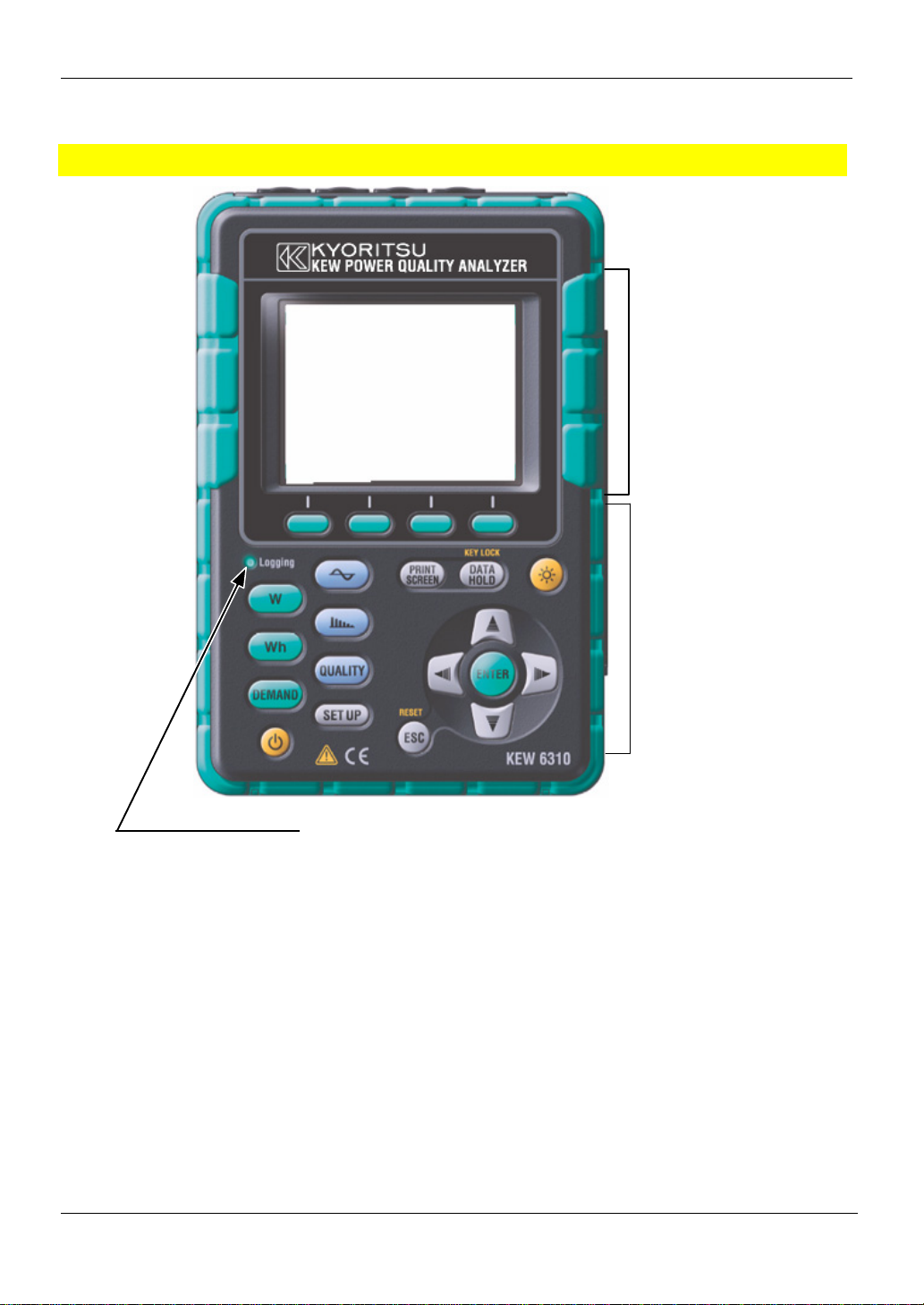
2.1 Front View
Display (LCD) / Keys
Display (LCD)
Keys
LED status indicator
Green lights up : Recording & measuring
Green flashes : Stand-by (lights up when preset time comes)
Red flashes : Charging batteries
2.1 KEW6310
Page 21
KEW6310 2.1 Front View
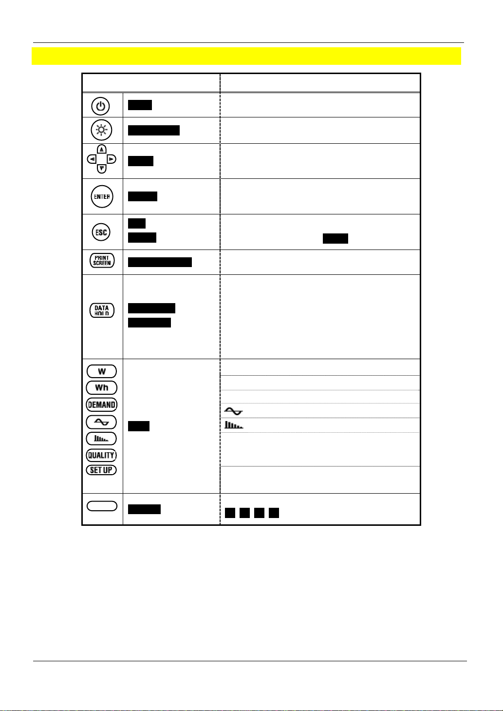
Key Operations
Keys Details
Power Key
LCD ON/OFF Key
Cursor Key
ENTER Key
ESC Key/
RESET Key
PRINT SCREEN Key
DA TA HOLD Key /
KEY LOCK Key
Menu Key
Power on / off the instrument
Display / hide the indications on the LCD
Select the setting items, switches screens
Confirm entries
Cancel setting changes, clear integration /
demand data selected by Cursor Keys.
Save the displayed screen as a BMP (bi tmap)
file.
● Hold the readings.
(can view the item an d system with Cursor Keys)
* Measurement continues even if screen is frozen.
● Key Lock
Pressing 2 sec or more disables all Keys to
prevent operational error. Another long press (2
sec or more) is required to restore the disabled
Keys.
W : Measure instantaneous values
Wh : Measure integration values
DEMAND : Measure demand values
: Waveform measurement
: Harmonic measurement
QUALITY: Select any Ch and set threshold
values to record swell/ di p/ int/ transient with time
information.
SET UP : Basic, Measurement, Save and Other
settings
Function Key
KEW6310 2.2
Execute the displayed function
F1, F2, F3, F4 Key (from left to right)
Page 22

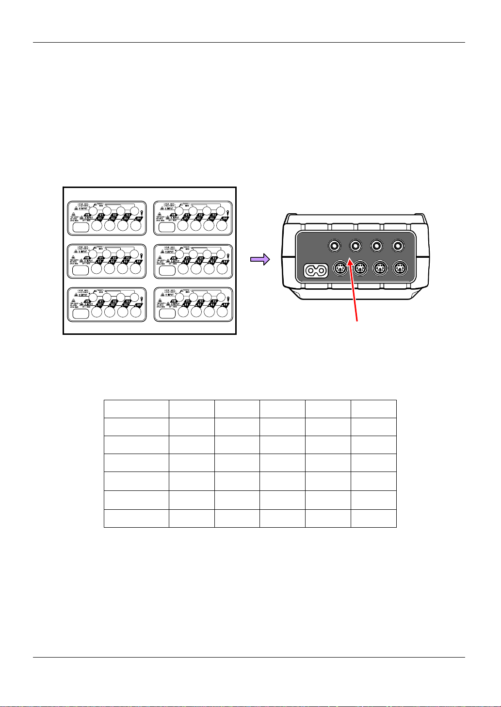
2.2 Connector KEW6310
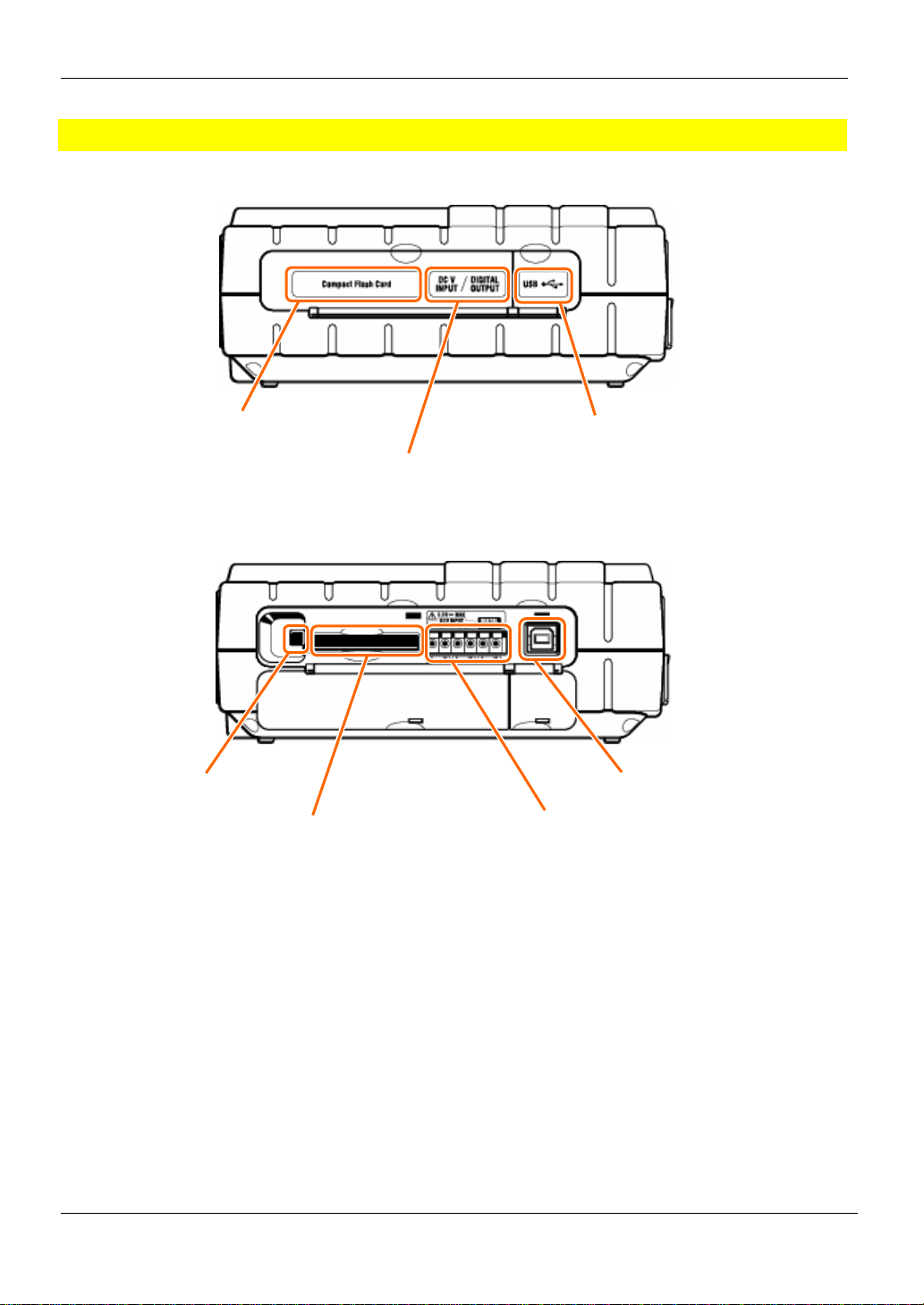
2.2Connector
Descriptions
Single-phase 2-wire (1c h ) “1P2W×1” VN, 1 A1
Single-phase 2-wire (2c h) “1P2W×2” VN, 1 A1, 2
Single-phase 2-wire (3c h ) “1P2W×3” VN, 1 A1, 2, 3
Single-phase 2-wire (4c h) “1P2W×4” VN, 1 A1, 2, 3, 4
Single-phase 3-wire (1c h) “1P3W×1” VN, 1, 2 A1, 2
Single-phase 3-wire (2c h) “1P3W×2” VN, 1, 2 A1, 2, 3, 4
Single-phase 3-wire (1 ch )
Three-phase 3-wire (1ch) “3P3W×1” VN, 1, 2 A1, 2
Three-phase 3-wire (2ch) “3P3W×2” VN, 1, 2 A1, 2, 3, 4
Three-phase 3-wire (1ch)
Three-phase 3-wire 3A “3P3W3A” V1, 2, 3 A1, 2, 3
Three-phase 4-wire (1ch) “3P4W×1” VN, 1, 2, 3 A1, 2, 3
Three-phase 4-wire (1ch)
Power Connector
Wiring configuration Voltage Input Terminal Current Input Terminal
+ 2 Current
+ 2 Current
+ 1 Current
“1P3W×1+2A” VN, 1, 2 A1, 2, 3, 4
“3P3W×1+2A” VN, 1, 2 A1, 2, 3, 4
“3P4W×1+1A” VN, 1, 2, 3 A1, 2, 3, 4
Volt age Inp ut Termina l
(VN, V1, V2, V3)
Current Input Terminal
(A1, A2, A3, A4)
Terminal Cover
2.3 KEW6310
Page 23
KEW6310 2.3 Side Face
2.3 Side Face
Descriptions
<when the Connector Cover is closed >
CF Card Cover
USB Port
<when the Connector Cover is closed >
Eject Button
Analogue Input/ Digital ou tput
CF Card Slot
USB Connector
Analogue Input/ Digital output T e rminal
KEW6310 2.4
Page 24
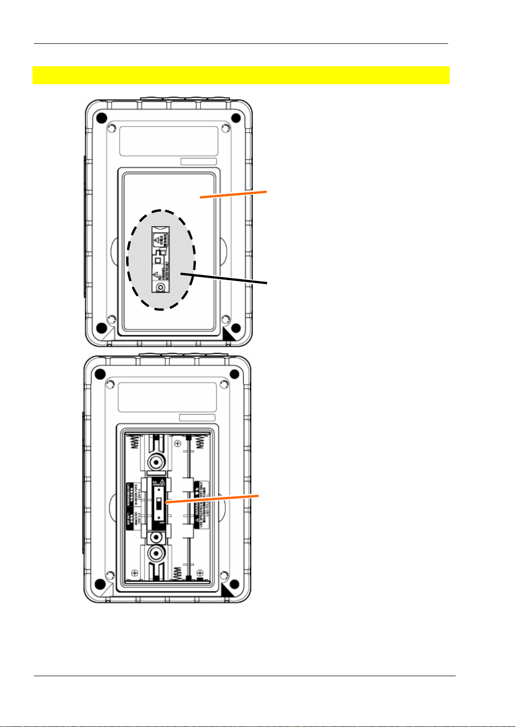
2.4 Battery Case KEW6310
2.4 Battery Case
Descriptions
Selector Switch Cover
Battery Cover
Selector switch cover
* Set the Selector Switch to either “DRY BATTERY” (alkaline) or “RECHAR GEABLE BATTERY” (Ni-MH)
position depending on the battery you use.
Selector switch
2.5 KEW6310
Page 25
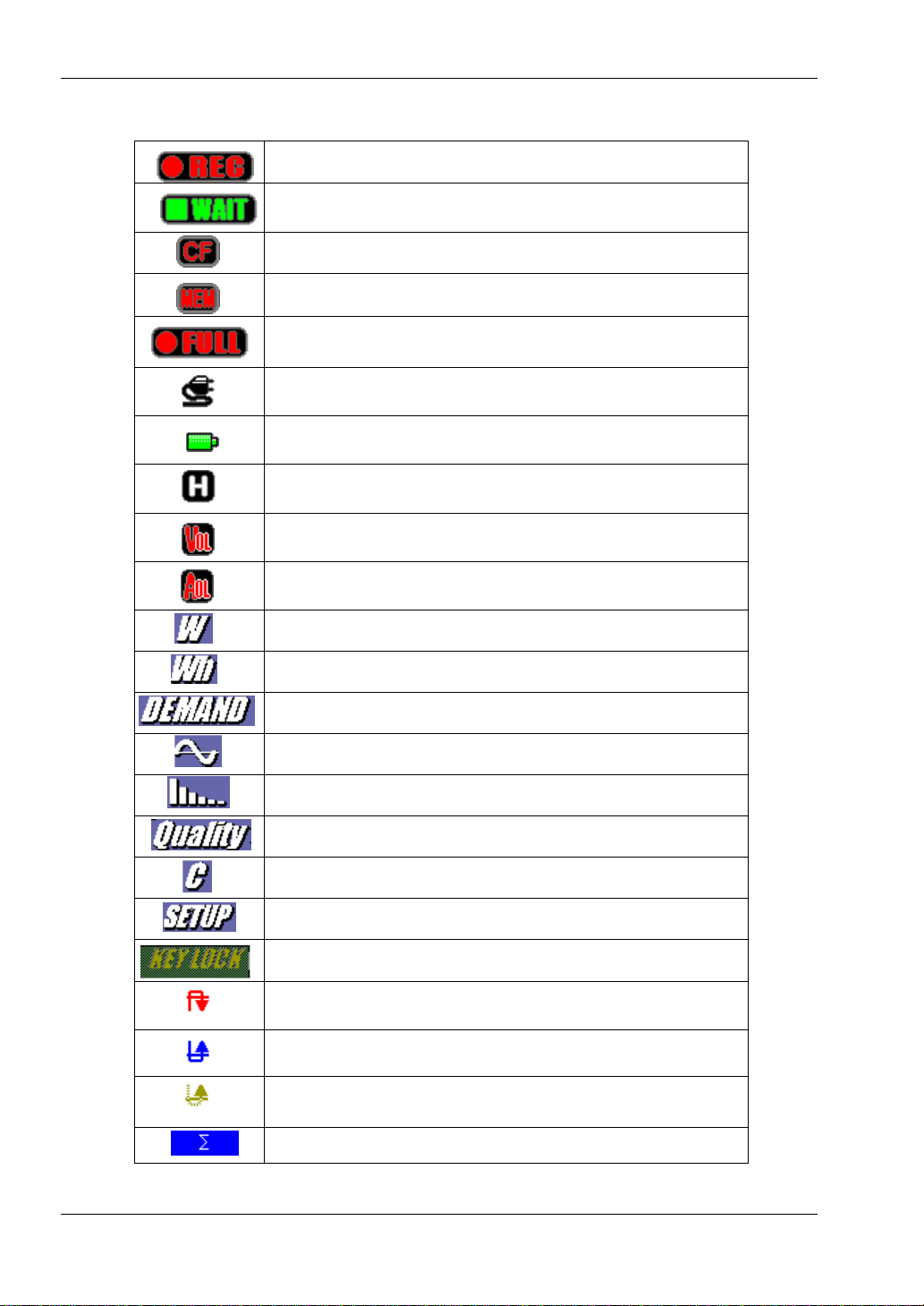
KEW6310 2.5 Marks displayed o n the LCD
2.5 Marks displayed on the LCD
Flash while saving data
Flash in stand-by mode
Flash while saving data to a CF Card
Flash while saving data to the internal memo ry
Displayed when the capacity of C F Card or the internal
memory is full
Displayed when KEW6310 is operating with AC power supply
Displayed when KEW6310 is operating with ba tteries
Displayed while Data hold functi on is activa ted
Displayed when measured voltage exceeds a certain condi tion
Displayed when measured current exceeds a cert ain condition
Displayed on the screen for Instantaneous value measurement
Displayed on the screen for Integra tion value me asurement
Displayed on the screen for Demand measure ment
KEW6310 2.6
Displayed on the WAVE Range screen
Displayed on the screen for Harmonic analysis
Displayed on the screen for Pow er quality measurement
Displayed on the screen for Capaci tance calculat ion
Displayed on the Setting screen
Displayed while Keys are locked
Displayed when swell occurs at Pow er quality measurement
Displayed when dip occurs at Pow er quality measure ment
Displayed when short-interruption (int) occurs a t Power quali ty
measurement
Displayed with sum of values measured at ea ch CH
Page 26
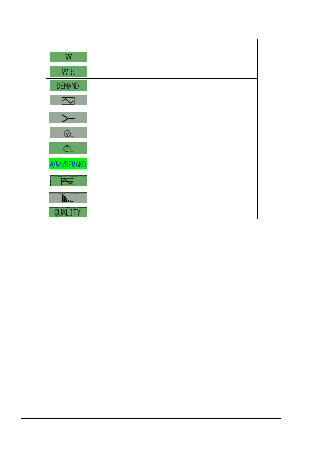
2.5 Marks displaye d on the LCD KEW6310
Marks for Function Keys
n
Switch to the screen for Instantaneous va lue measurement
Switch to the screen for Integration value measuremen t
Switch to the screen for Demand measurement
Switch to the screen for Wave form measurement
Switch to the V ecory display screen
Change scale of voltage at th e screen for Waveform
measurement
Change scale of current at the screen for Wave form
measurement
Switch to W/ Wh/ DEMAND Setting screen
Switch to WAVE Range Setting screen
Switch to Harmonic analysis Setting screen
Switch to Power quality Setting screen
2.7 KEW6310
Page 27

KEW6310 2.5 Marks displayed on the LCD
KEW6310
2.8
Page 28
3.1.1 Putting a Connector plate on the Input terminal KEW6310
3. Getting started
3.1 Preparation
3.1.1 Putting Input terminal plate on the Input terminal
Six Input terminal plates are supplied with this instrument. Choose one Plate which matches the standard
cord colors where the instrument is used. Put the Plate to the Input terminal observing the orientation.
* Clean the Input terminal before putting the Plate and confirm it isn’t wet.
TYPE1
TYPE4
TYPE2
TYPE3
TYPE5
TYPE6
Put a proper Input terminal plate.
Input terminal plate.
VN V1/A1 V2/A2 V3/A3 A4
TYPE 1 Blue Red Green Black Yellow
TYPE 2 Blue Brown Black Gray Yellow
TYPE 3 Black Yellow Green Red White
TYPE 4 Blue Black Red White Y ellow
TYPE 5 White Black Red Blue Yellow
TYPE 6 Black Red Yellow Blue White
3.1 KEW6310
Page 29
KEW6310 3.1.2 Attaching Markers to Voltage test leads and Clamp sensors
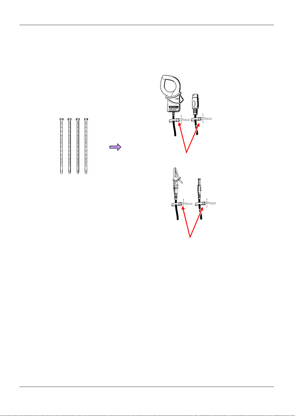
3.1.2 Att aching Markers to Voltage test leads and Clamp sensors
Attach Markers to the both ends of the Voltage test leads and Clamp sensors harmonized with the Input
terminals. * Supplied Markers are 32 pcs in total : 4pcs each color (red, blue, yellow, green, brown, gray,
black, white).
Attach Markers to the both ends of a Sensor .
Marker (32 pcs in total)
Attach Markers to the both ends of the Voltage test lead.
KEW6310 3.2
Page 30
3.2.1 Battery KEW6310
3.2 Power Supply
3.2.1 Battery
KEW6310 operates with either an AC power supply or batteries. Capable o f pe rformi ng measure ment s in the
event of AC po w er in terru ption , power to the instrument is automatically restored by the batteries inst all ed i n
the instrument. Dry-cell batteries (alkaline) and rechargeable batteries (Ni-MH) can be both used. It is also
possible to charge rechargeable batte ries in the instrument.
* Dry-cell batteries (alkaline) are supplied as accessories.
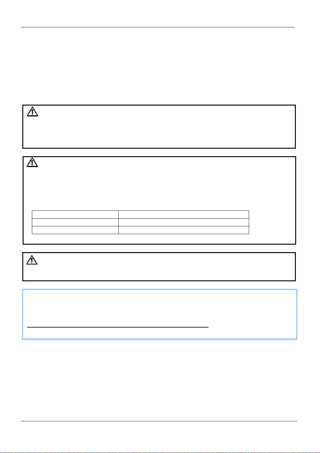
DANGER
● Never open the Battery Cover during a measurement.
● Brand and type of the batteries to be used should be harmonized.
● Never touch the Power su pply conne ctor al thou gh it is insu l ated w hile the instrumen t is opera ti ng w ith
batteries.
WARNING
● Remove Power Cord, Voltage test leads and Clamp sensors from the instrument and power off the instrument
before replacing the batteries.
● Remove the Selector Switch Cover, and slide the Selector Switch to left or right depending on the batteri es to
be used. Do not use dry-cell batteries with the Selector Switch set to “RECHARGEABLE BA TTERY” position.
It may cause electrical shock accident.
Position of Selector Switch Battery can be used
RECHARGEABLE BATTER Y size AA Ni-MH rechargeab le ba ttery (HR- 15/5 1)
DRY BATTERY size AA dry-cell alkaline battery (LR6)
CAUTION
● Do not mix new and old batteries.
● Install batteries in correct polarity as marked inside.
Batteries are not in the instrument at the time of purchase. Please insert the supplied batteries in the
instrument. Battery power is consumed even if the instrument is being off. Remove all the batteries if the
instrument is to be stored and w ill no t be in use fo r a long peri od . When the instrumen t i s po w ered by an AC
power supply, it doesn’t operate with batteries.
If an AC supply is interrupted and the batteries hav e not been inserte d, the instrument goes off and a ll
data may lost.
3.3 KEW6310
Page 31

KEW6310 3.2.1 Battery
Display
Mark of power supply changes as follow s.
AC power supply-operated Battery-ope rate d*
mark flashes while charging batteries.
Battery Condition
Battery mark varies as follows depending on battery condition.
Alkaline dry battery (LR6) Ni-MH Rechargeable battery (HR-15/51)
Batteries are exhausted. (Accuracy of readings cannot be guaranteed)
In this case, the instrument operates as follows automatically.
about 2 hours
Measurement continues, but data saving stops.
(Measured data is saved)
Measurement / data saving stops.
(Measured data is saved)
*
autonomy about 5 hours* autonomy
Battery level is di sp layed by 20% levels.
* reference time when using the instrume n t w ith indi ca tion s on the LCD hi de
KEW6310 3. 4
Page 32

3.2.1 Battery KEW6310
Inserting dry-cell batteries
1 Loosen two Battery Cover-fixing screws and remove the Cover.
2 Take out all the batteries.
3 Loosen the screws and remove the Selector Switch Cover.
Attention should be paid so as not to lose the screws.
4 Slide to left and set the Selector Switch to “DRY” position.
5 Install the Selector Switch Cover with the marking of dry battery faced up, and tighten the screws.
6 Insert batteries (LR6 : size AA alkaline batteries) in correct polarity.
7 Inst all the Battery Cover and tighten two screws.
8 Connect the AC Power Cord and power on the instrument.
Slide and set the Selector Switch to the proper position prior to installing the Selector Switch Cover.
The instrument should be used with the Switch set to a proper position. Never make measurement without
installing the Cover.
3.5 KEW6310
Page 33

KEW6310 3.2.1 Battery
Rechargeable batteries
This instrument can charge rechargeable batteries via AC power supply.
1 Loosen two Battery Cover-fixing screws and remove the Cover.
2 Take out all the batteries.
3 Loosen the screws and remove the Selector Switch Cover.
Attention should be paid so as not to lose the screws.
4 Slide to left and set the Selector Switch to “RE-CHARGEABLE” position.
5 Install the Selector Switch Cover with the marking of rechargeable battery faced up, and tighten the
screws.
6 Insert batteries (HR-15/51 : size AA Ni-MH rechargeable batteries) in correct pol arity.
7 Inst all the Battery Cover and tighten two screws.
8 Connect the AC Power Cord and power on the instrument.
~ Battery charge ~
Message windows on the next p ag e appe a r when st a rting the instru me nt un der fol lowing conditions and with
battery level of 40% or less.
* Install rechargeable ba tterie s (N i-MH )
* Slide and set the Selector Switch to “RE-CHARGEABLE” position.
* Connect the AC Power cord and power on the instrument.
Refer to “4.2.4 Other Settings” and see the procedure to start battery charge any time.
9 Follow the message displayed on the LCD and press the Cursor and ENTER Keys to start
charging batteries. Selecting “No” returns to the normal screen.
Battery charge doesn’t initiate only by installing rechargeable batteries and connecting an AC power cord.
Above operation is required to start a battery charge.
KEW6310 3.6
Page 34

3.2.1 Battery KEW6310
Battery charge starts and the screen returns to normal.
● Charging batteries
Indications on the instrument during a charging are as follows.
Indications
LCD ON Battery mark on the LCD flashes.
LED status indicator doesn’t light up.
LCD OFF or
Instrument is OFF
Slide and set the Selector Switch to the proper position prior to installing the Selector Switch Cover.
The instrument should be used with the Switch set to the proper position. Never make measurement without
installing the Cover.
LED status indicator flashes in red.
LED status indicator flashes in green w hile
recording data.
3.7 KEW6310
Page 35

KEW6310 3.2.1 Battery
Charging cycle is 5 min, and charging patterns vary as follows depending on the instrument condition. This is
to control temperature rises on the instrument resulting from battery charge.
Pattern Charging Pause Total
charging time
I. Power
II. Power
III. Power
ON (LCD_ON)
ON (LCD_OFF)
OFF
4.2 min 0.8 min 7h
0.7 min 4.3 min 48h
2.1 min 2.9 min 14h
KEW6310 3.8
Page 36

3.2.2 AC Power Supply KEW6310
3.2.2 AC Power Supply
Check the followings before connecting the Power cord.
DANGER
● Use only the Power cord supplied with this instrument.
● Connect the Power cord mains plug to a ma in s socke t outle t. The mains supply voltage must not exceed
AC240V. (max rated voltage of supplied Power cord MODEL7169 : AC125V)
WARNING
● Confirm that the instrument is powered off, and then connect the Power cord.
● Connect the Power cord to the instrument first. Cord to be firmly inserted.
● Never attempt to make measuremen t if any abnormal cond ition s such as a bnorma l con dit ion s are no ted,
such as a broken Cover and exposed metal parts.
● When the instrument is not in use, disconnect the Power cord from the outlet.
● When unplugging the cord from the mains socket outlet, do so by removing the plug first and not by
pulling the cord .
Power cord connection
Follow the procedure below, and connect the Power cord.
1 Confirm that the instrument is powered off.
2 Connect the Power cord to the Power connector on the instrument.
3 Connect the Power cord plug to a mains socket outlet.
Power supply rating
Following table show s the Power supply rating.
Rated supply voltage : 100 ~ 240V AC(±10%)
Rated power supply frequency : 45 ~ 65Hz
Max power consumption : 20VA max
3.9 KEW6310
Page 37

KEW6310 3.3 Voltage test leads and Clamp sensor connection
3.3 Voltage test leads and Clamp sensor connection
Check the followings before connection.
DANGER
● Use only the Voltage test leads supplied with this instrument.
● Use the dedicated Clamp sensor for this instrument, and confirm that the measured current rating of the
Clamp sen sor i s no t ex ceed ed.
● Do not connect all the Voltage test leads or Clamp sensors unless required for measuring the parameters
desired.
● Connect the test leads and sensors to the instrument first, and only then connect them to the circuit
under test.
● Never disconnect the Voltage test leads and sensors while the instrument is in use.
WARNING
● Confirm that the instrument is powered off, and then connect the Power cord.
● Connect the Power cord to the instrument first. Cord to be firmly inserted.
● Never attempt to make measuremen t if any abnormal cond ition s such as a bnorma l con dit ion s are no ted,
such as a broken Cover and exposed metal parts.
Voltage test leads and Clamp sensor connection
Follow the procedure below, and connect the Voltage test leads and Clamp sensors.
1 Confirm that the instrument is powered off.
2 Connect the appropriate Voltage test leads to the Voltage input terminal on the instrument.
3 Connect the appropriate Clamp sensors to the Current input terminal on the instrument. Match the direction of
the arrow mark indicated on the output terminal of the clamp sensor and the mark on the Current input
terminal on the instrument.
* Number of Voltage test leads and Clamp sensors to be used depends on the wiring configuration under
test. For further details, refer to “5.2 Basic Wiring Configuration” in this manual.
Match the arrow marks.
KEW6310
3.10
Page 38

3.4.1 Start-up Screen KEW6310
3.4 Start KEW6310
3.4.1 Start-up Screen
Hold down the POWER Key until the Start-up screen is displayed. Pressing the POWER Key for 2 sec or more
powers off the instrument. Following screen is displayed when the instrument is on.
1 MODEL/VERSION screen is displayed, and a self-check routine starts. Then KEW logo will appear.
2 Previous screens displayed at last operation are back on.
3.11 KEW6310
Page 39

KEW6310 3.4.1 Start-up Screen
KEW6310 3.12
Page 40

3.4.2 Error message KEW6310
3.4.2 Error message
Following screen may appear after a self-check routine.
● When a failure is detected;
This instrument automatica lly checks the inte rnal circui t im media tely a fter i t is powered on.
If a suspect failure in the internal circuit is detected, the error screen below will be displayed for about 5 sec.
In this case, refrain from using the instrument and refer to “Section15: Troubleshooting” in this manual.
CAUTION
Notwithstanding the error scre en, the me asur ement scre en w ill appea r and the in stru men t w ill take
measurements anyway. However, accurate readings may not be obtained.
● When connected sensors are changed;
Clamp sensors connected are displayed for 5 sec as follows. When no sensor is connected, previous
settings are kept.
3.13 KEW6310
Page 41

KEW6310 3.4.2 Error message
● When CF card needs to be formatted;
Following screen is displayed for 5 se c w hen a CF Ca rd ha s to be forma tted.
* Only the CF Card formatted via FAT system can be used with this instrument.
Select “Yes” to format the CF Card.
* All the data saved in the CF Card will be cleared.
CF Card cannot be selected as a destination to save data if “No” is selected.
Refer to “12.3 CF Card / Internal memory” in th is manu al w hi ch sh ow s how to format a CF Card.
KEW6310 3.14
Page 42

4.1 List of Setting items KEW6310
4. Setting
4.1 List of Setting items
Settings for measurement condition and data savi ng a re necessa ry prio r to making measur ement s . Press the
Key to enter into SET UP mode and do necessary settings.
Setting screens consists of following screens.
Wiring
Basic Setting
V Range
VT Ratio
Basic
Clamp
A Range
CT Ratio
Filter
DC V
Frequency
Interval
Measurement Setting
Measurement
(W/Wh/DEMAND)
F1
Save Items
Target Demand
Demand Inspection Cycle
Pressing the Keys moves to:
* Basic Setting
* Measurement Setting
* Save Setting
* Other Setting
Measurement
( )
F2
Measurement
( )
F3
Interval
Save Items
Interval
THD Calculation
Allwoable Range
MAX HOLD
Save Items
4.1 KEW6310
Page 43

KEW6310 4.1 List of Setting items
Measurement
( )
Save Setting
Save
(1/2)
Swell / Dip / Int Measurement
Transient Measurement
F4
Inrush current Measurement
Unbalance rate measurement
Flicker*
Capacitance calculation
Recording Method
Recodring Start
Recording End
Destination to Save data
Destination to Save screenshot
Interval*
Reference Voltage
Transient*
Swell
Dip
Int (short-interruption)
Hysteresis
Trigger point
Interval*
Volt age Ra nge
Threshold value
Hysteresis
Trigger point
Interval*
Clamp
Current Range
Reference Current
Filter
Threshold value
Hysteresis
Trigger point
Interval
Output threshold value
V Range
Filter
Output item
Output Threshold
Interval
Target Power Factor
Formatting CF Card
Deleting the data in CF Card
Formatting Internal Me mo ry
Save
(2/2)
Other Setting
Other
(1/2)
Other
(2/2)
* Flicker measurement function is only available with ver.2.00 or later.
KEW6310 4.2
Deleting the data in Internal Memory
Data transfer (from Internal Memory to CF Card )
Loading Setting
Save Setting
Language
Date Format
Time and Date
Buzzer
CSV File
ID Number
LCD Contrast
CH Color
Auto-Power-Off
LCD-Auto-Off
Battery Charge
System Reset
Page 44

4.2.1 Basic Setting KEW6310
4.2 Settings
4.2.1 Basic Setting
Wiring Configuration
① 1P2W×1 Single-phase 2-wire (1ch ) ⑩ 3P3W×1+2A
② 1P2W×2 Single-phase 2-wire (2ch ) ⑪ 3P3W3A Three-phase 3-wire 3A
③ 1P2W×3 Single-phase 2-wire (3ch ) ⑫ 3P4W×1 Three-phase 4-wire (1ch)
④ 1P2W×4 Single-phase 2-wire (4ch ) ⑬ 3P4W×1+1A
⑤ 1P3W×1 Single-phase 3-wire (1ch )
⑥ 1P3W×2 Single-phase 3-wire (2ch )
⑦ 1P3W×1+2A
⑧ 3P3W×1 Three-phase 3-wire (1ch)
⑨ 3P3W×2 Three-phase 3-wire (2ch) 4A 4-current
* Default value (or after system reset) : ⑬ 3P4W×1+1A
* Wiring of 4A can be selected only at W Range. Default value is adopted when selecting the other Ranges.
Single-phase 3-wire (1 c h) +
2-current
0
0
1 Press the Cursor Keys and select [Wiring], and then press the ENTER Key.
Three-phase 3-wire (1ch) +
2-current
Three-phase 4-wire (1ch) +
1-current
2 Press the Cursor Keys and select a proper wiring configuration, and then press
the ENTER Key.
List of wiring
configuration appears.
Selected wiring configuration is displayed.
4.3 KEW6310
Page 45

KEW6310 4.2.1 Basic Setting
Check of Connection diagram
Connection diagram can be viewed at selecting a wiring configuration.
Move to a screen for selecting a wiring configuration. Use the Cursor Key s to select a wiring
configuration, and then press the F4 Key.
Press the F4 Key to display the connection
diagram for the selected wiring configuration.
F1 Key / Key : to view preceding connection diag ra m
F2 Key / Key : to view subsequent connection diagram
F4 Key / ESC Key : returns to SET UP screen for selecting wiring configuration
ENTER Key : confirms the selected wiring configuration and returns to Basic Setting Screen
Selected connection diag ram i s di sp lay ed.
KEW6310 4.4
Page 46

4.2.1 Basic Setting KEW6310
Setting for Voltage Range
150V 300 V 600V 1000V
* Default value (or after system reset) : 300V
1 Press the Cursor Keys and select [V Range], and then press the ENTER Key.
2 Press the Cursor Keys and select a desirable voltage value, and then press the
ENTER Key.
Drop down list appears.
Selected voltage value is displayed.
4.5 KEW6310
Page 47

KEW6310 4.2.1 Basic Setting
p
Setting for VT Ratio
0.01 ~ 9999.99 (can be set by 0.01)
* Default value (or after system reset) : 1.00
For the details of VT ratio, refer to “5.4 VT / CT Ratio” in this manual.
1 Press the Cursor Keys and select [VT Ratio], and then press the ENTER Key.
2 Press the Cursor Keys and alter the values, and press the ENTER Key
to fix it.
Press the Cursor to toggle the
value from 0 to 9.
When increasing a value to 0 in ascending sequence,
value at the tents'
Press the Cursor to toggle the
value from 9 to 0.
lace increases by 1.
Box with ▲▼ mark appears
at the hundredths' place .
KEW6310 4.6
Page 48

4.2.1 Basic Setting KEW6310
In case that a preset value is 0000.01, the hundreds’ place cannot be altered in descending
sequence. Similarly, if a preset value is 9999.99, thousand’s place cannot be altered in ascending
sequence.
Press the Cursor to move to lower places.
When decreasing a value to 0 in descending sequence,
value at the tents' place decreases by 1.
Press the Cursor to move to upper places.
Selected VT ratio is displayed.
4.7 KEW6310
Page 49

KEW6310 4.2.1 Basic Setting
Setting for Clamp sensor
Model names and rated currents of Clamp sensors are listed as follows.
Clamp sensors for
Power measurement
8128
50A ty pe
Leakage Clamp sensor
8141
1A type
8127
8126
8125
8124
8129
100A ty pe
200A ty pe
500A ty pe
1000A type
3000A type
8142
8143
8146
8147
8148
1A type
1A type
10A ty pe
10A ty pe
10A ty pe
* Default value (or after system reset) : 8125
* Clamp sensors for measurements other than power are available only at
following wiring configurations.
Number of available Clamp sensor depends on a wiring configuration to be measured.
① 1P2W×1
1ch
② 1P2W×2 1ch 2ch
③ 1P2W×3 1ch 2ch 3ch
④ 1P2W×4 1ch 2ch 3ch 4ch
⑤ 1P3W×1
⑧ 3P3W×1
⑥ 1P3W×2
⑨ 3P3W×2
⑦ 1P3W×1+2A
⑩ 3P3W×1+2A
1,2ch
System 1(1,2ch) System 2(3,4ch)
1,2ch 3ch 4ch
⑪ 3P3W3A
⑫ 3P4W×1
1,2,3ch
⑬ 3P4W×1+1A 1,2,3ch 4ch
0
4A 1ch 2ch 3ch 4ch
* Default value (or after system reset) : ⑩ 1,2,ch 3, 4ch
* Channels highlighted in light y ellow are appli cable only to Clamp sen sors for
power measurement.
* Channels highlighted in gray are app licable to Clamp sensor s for power
measurement and Leakage Clamp sensors.
KEW6310 4.8
Page 50

4.2.1 Basic Setting KEW6310
Manual setting and auto setting both are available for Clamp sensors.
<< Manual Setting >>
1 Press the Cursor Keys and select [Clamp], and then press the ENTER Key.
2 Press the Cursor Keys and select a Clamp sensor to be used, and then press the
ENTER Key.
Drop down list appears.
Selectable Clamp sensors
depend on the selected wiring
configurations.
Selected Clamp sensor is displayed with
corresponding Ch.
4.9 KEW6310
Page 51

KEW6310 4.2.1 Basic Setting
When setting for [Clamp] is done, the upper
limit of measuring range of the selected
sensor is displayed au tomatically.
3 Press the Cursor Keys and select Clamp sensors to be used at th e o ther CH, an d
make settings in the same way.
Settings for [Clamp] and [A Range] are active in subsequent measurements, but they w ill ch ang e
when preset wiring configurations are chang ed. The highest Range is applied to all Chs when the
[A Range] at each Ch should be harmonized due to a change of wiring configurations.
KEW6310 4.10
Page 52

4.2.1 Basic Setting KEW6310
<< Auto Setting >>
Model name of the Clamp sensor connected to the Current Terminal of the instrument is detected automatically at Auto setting mode. Setting for [Wiring] should be don e to ad vance Auto setting.
1 Confirm that settings for [Wiring] are made, and then press the F2 Key.
The max measurable values on Clamp sensor are reflected in setting for [A Range].
[CT ratio] is automatically set to 1.00.
For [Filter], bars are displayed when the detected senso rs are MODEL8 12X series and OFF is
displayed when the sensors are MODEL814X se ries .
Pressing the F2 Key initiates
auto setting for Clamp sensor.
Connected Clamp sensors are automatically
detected, and settings for [A Range], [CT ratio]
and [Filter] are made automati ca lly.
Setting will be changed if new sensors are detected at powering on the instrument.
4.11 KEW6310
Page 53

KEW6310 4.2.1 Basic Setting
The instrument detects and checks the connected Clamp sensors and the selected wiring configuration, and
displays following messages when improper Clamp sensors are connected.
< Improper Clamp sensor is detected >
Recheck and connect proper Clamp sensors.
< No sensor is detected >
Model names of the connected
Clamp sensors are displayed. Bars
are displayed at A range, CT ratio
and Filter boxes.
Check the Clamp sensor connected to the Current input terminal corresponding to the Ch number
displayed with question mark.
When starting measurement with the question mark displayed at the [Clamp] box, previous setting
is applied automatically.
Question mark “?” is displayed at Model
name and Current range boxes. C T rati o is
automatically se t to 1.0 0. Ba rs are di splay ed
at Filter box.
Question mark “?” is displayed at Model
name box.
CT ratio is automatically set to 1.00.
Bars are displayed at Filter box.
KEW6310 4.12
Page 54

4.2.1 Basic Setting KEW6310
Setting for Current Range
Available Current Range varies depending on the Clamp sensor to be used.
8128 1/5/10/20/50A/AUTO
8127 10/20/50/100A/AUTO
8126 20/50/100/200A/AUTO
8125 50/100/200/500A/AUTO
8124 100/200/500/1000A/AUTO
8129 300/1000/3000A
8141
8142
8143
8146
8147
8148
* Default value (or after system reset) : 200A(8125)
100mA/500mA/1A/AUTO
500mA/1/5/10A/AUTO
1 Press the Cursor Keys and select [A Range], and then press the ENTER Key.
4.13 KEW6310
Page 55

KEW6310 4.2.1 Basic Setting
2 Press the Cursor Keys and select a Current Range to be used , and then press the
ENTER Key.
Drop down list appears.
Selected Current Range per Ch
is displayed.
When setting for [Clamp] is done, the
upper limit of measuring range of the
selected sensor is displayed automatically.
3 Press the Cursor Keys and select Clamp sensors to be used at th e other Ch , and
make settings in the same way.
Settings of [Clamp] and [A Range] are active in following measurement s, bu t they will chang e when
preset wiring configurations are changed. The highest Range is applied to all Chs when the
[A Range] at each Ch should be harmonized due to a change of wiring configurations.
KEW6310 4.14
Page 56

4.2.1 Basic Setting KEW6310
(A)
g
g
Display range and guaranteed accuracy range for each Current Range are as follows.
50ARange
20ARange
8128
10ARange
5ARange
1ARange
100ARange
50ARange
8127
8126
8125
8124
8129
8141/
42/43
8146/
47/48
20ARange
10ARan
200ARange
100ARange
50ARange
20ARange
500ARange
200ARange
100ARange
50ARange
1000ARange
゙
500ARange
200ARange
100ARange
3000ARange
1000ARange
300ARange
1ARange
0.5ARange
0.1ARan
10ARange
5ARange
1ARange
0.5ARange
Sensors: 8141/42/43 and 8146/47/48 cannot be used for power measurements.
e
0.001
e
0.001 0.01 0.1 1 10 100 1000 10000
0.01
0.01
0.005
0.01
0.005
0.1
0.05 6
0.1 1.1
0.1
0.05
0.05
0.1
0.05
0.5
0.2
5
2
12
111
0.5
1.2
5.5
1
0.5
0.2 24
10 110
555
222
12
111
2
1 120
20
10
0.2 24
2
5
2
1
20
10
5
1
20
10
3
1.2
1.10.1
0.6
0.12
0.55
0.110.01
120.1
111
6
0.5
0.6
1.2
1.1
5.5
0.55
電流(A)
60
55
24
22
120
60
240
220
110
600.5
555
22
50 550
240
220
120
11010
600.5
555
50
120
2402
220
11010
30
Display range
Accuracy range
600
1200
1100100
600
550
360030
3300300
1200
1100100
360
330
4.15 KEW6310
Page 57

KEW6310 4.2.1 Basic Setting
Setting for CT ratio
0.01 ~ 9999.99 (can be set by 0.01)
* Default value (or after system reset) : 1.00
For the details of CT ratio, refer to “5.4 VT / CT Ratio” in this manual.
1 Press the Cursor Keys and select [CT Ratio], and then press the ENTER Key.
2 Setting procedure is same to that for VT ratio. Refer to the procedure described in the
preceding pages.
3 Press the Cursor Keys and select CT ratio for the other Chs, and make settings in the
same way.
KEW6310 4.16
Page 58

4.2.1 Basic Setting KEW6310
Setting for Filter
Lowpass filter activate to cut frequ en cies in highe r harmon ic band when se t the Fil te r fu nction “ON”.
(Cutoff frequency : approx 160Hz)
Filter
Wiring
Clamp Sensor 8141/42/43/46/47/48 8128/27/26/25/24/29
* Default value (or after system reset) : ----- or OFF
* Bar “------“ is displayed for the Filter other than listed above, and a setting cannot be made.
1 Press the Cursor Keys and select [Filter], and then press the ENTER Key.
Available (ON⇔OFF)
⑦1P3W x 1+2A 3,4ch
⑩3P3W x 1+2A 3,4ch
⑬3P4W x 1+1A 4ch
0
4A
Not available (------)
2 Press the Cursor Keys and select “ON” or “OFF”, and then press the ENTER Key.
Drop down list appears.
Incapable of selecting ON/OFF
depending on the connected Sensors.
Selected Filter setting (ON or OFF) is displayed.
3 Press the Cursor Keys and select ON / OFF for the other Chs, and make settings in the
same way.
4.17 KEW6310
Page 59

KEW6310 4.2.1 Basic Setting
Setting for DC V
Setting for V ol t age Range a t anal ogue inp ut termina l ca n be ma de accordi ng to the pro cedure below.
50mV 500mV 5V
* Default value (or after system reset) : 5V
1 Press the Cursor Keys and select [DC V], and then press the ENTER Key .
2 Press the Cursor Keys and select a DC Range to be used, and then press the ENTER Key.
Drop down list appears.
DC Range selected for 1ch is displayed.
3 Press the Cursor Keys and select DC Range for 2ch, and make settings in the
same way.
KEW6310 4.18
Page 60

4.2.1 Basic Setting KEW6310
Setting for Frequency
Frequency of the fixed clock can be chan ged acco rd ing to fol lo w ing procedu re when PLL synchronized
measurement cannot be made.
50Hz 60Hz
* Default value (or after system reset) : 50Hz
1 Press the Cursor Keys and select [Freq], and then press the ENTER Key.
2 Press the Cursor Keys and select “50Hz” or “60Hz”, and then press the ENTER Key.
Drop down list appears.
Selected frequency is displayed.
4.19 KEW6310
Page 61

KEW6310 4.2.1 Basic Setting
KEW6310 4.20
Page 62

4.2.2 Measurement setting (W/Wh/DEMAND) KEW6310
4.2.2 Measurement setting
W/ Wh/ DEMAND
Press the F1 Key at Measurement setting screen to move to the setting screen for W/ Wh/ DEMAND Range.
Setting for interval
Interval is a space of the ti me betw een da t a savi ngs; da t a is saved in a CF ca rd or In te rnal memory.
1 sec
1 min
2 sec
5 sec
10 sec
15 sec
20 sec
30 sec
* Default value (or after system reset) : 30 min
2 min
5 min
10 min
15 min
20 min
30 min
1 hour
1 Press the Cursor Keys and select [Interval], and then press the ENTER Key.
2 Press the Cursor Keys and select any desirable interval, and then press the
ENTER Key.
Drop down list appears.
Selected interval is displayed.
4.21 KEW6310
Page 63

KEW6310 4.2.2 Measurement setting (W/Wh/DEMAND)
Setting for inst / avg / max / min values
Select “ON” for the parameters to be saved.
ON⇔OFF
* Default value (or after system reset) : ON
1 Press the Cursor Keys and select any of [Inst / Avg / Max / Min], and then press the
ENTER Key.
Point a parameter to change the setting.
2 Press the Cursor Keys and select “ON” or “OFF”, and then press the ENTER Key.
Drop down list appears.
ON / OFF is displayed.
When an interval is set to 1 sec, Inst value= Avg value= Max value = Min value. In this case, only Inst
values are recorded. (“ON” is available only for Inst) Incapable of applying “OFF” to all the items.
3 Press the Cursor Keys and make settings for [Avg / Max / Min] as well.
KEW6310 4.22
Page 64

4.2.2 Measurement setting (W/Wh/DEMAND) KEW6310
Setting for detailed items
Parameters saved under ON or OFF setting for Detailed item are listed below.
ON OFF
WP+ / WP- O O
WS+ / WS- O X
WQi+ / WQc+ O O
WQi- / WQc- O X
Each CH O X
ON⇔OFF
* Default value (or after system reset) : ON
1 Press the Cursor Keys and select [Detailed item], and then press the ENTER Key.
2 Press the Cursor Keys and select “ON” or “OFF”, and then press the ENTER Key.
Drop down list appears.
ON / OFF is displayed.
4.23 KEW6310
Page 65

KEW6310 4.2.2 Measurement setting (W/Wh/DEMAND)
Setting for Target demand
For the details of target demand, refer to “Section8 Demand measurement” in this manual.
1.000 ~ 999.9(can be set by 0.1) mW/W/kW/MW/GW/TW
* Default value (or after system reset) : 300.0kW
1 Press the Cursor Keys and select [Demand Target], and then press the ENTER Key.
2 Press the Cursor Keys and alter the values.
KEW6310 4.24
Page 66

4.2.2 Measurement setting (W/Wh/DEMAND) KEW6310
3 Use the Cursor Keys and set multipliers.
Multiplier Setting
As a target dema nd , values within a range between 1000 and 9999 can be used.
To select a value 1000 or less, minus multiplier should be used.
100.0 = 1000 x 10 -1
10.00 = 1000 x 10 -2
1.000 = 1000 x 10 -3
4 Press the Cursor Keys and a select proper unit, and then press the ENTER Key.
Selected target demand is displayed.
.
4.25 KEW6310
Page 67

KEW6310 4.2.2 Measurement setting (W/Wh/DEMAND)
Setting for Demand inspection cycle
For the details of Demand inspection cycle, refer to “Section 8 Demand measurement” in this manual.
Demand Interval
1 sec
2 sec
5 sec
10 sec 1sec/2sec/5sec
15 sec 2sec/5sec/10sec
20 sec 5sec/10sec/15 sec
30 sec 10sec/15sec/20sec
1 min 15sec/20sec/30sec
2 min 20sec/30sec/1min
5 min 30sec/1min/2min
10 min 1min/2min/5min
15 min 2min/5min/10min
20 min 5min/10min/15min
30 min 10 mi n/15min /2 0min
1 hour 15min/20min/30min
* Default value (or after system reset) : 10 min
Demand Inspection Cycle
invalid
KEW6310 4.26
Page 68

4.2.2 Measurement setting (W/Wh/DEMAND) KEW6310
1 Press the Cursor Keys and select [Demand Inspection], and then press the ENTER Key.
2 Press the Cursor Keys and select a desirable cycle, and then press the ENTER Key.
Demand Inspection Cycle listed on the drop down list depends on the selected interval.
Change the interval setting first w hen a desira ble cycl e isn’t li sted on the drop dow n list.
Drop down list appears.
Selected Demand Inspection Cycle is displayed.
4.27 KEW6310
Page 69

KEW6310 4.2.2 Measurement setting (WAVE Range)
KEW6310 4.28
Page 70

4.2.2 Measurement setting (WAVE Range) KEW6310
WAVE Range Setting
Press the F2 Key at each Measurement setting screen, and move to the screen for WAVE Range Setting.
Setting for interval
* Default value (or after system reset) : 30 min
* Setting procedure is same to that for interva l Setting for W/ Wh/ DEMAND.Refer to the procedure described in
the preceding pages.
Interval listed on the drop down list depends on the number of save items with “ON” setting. Alter
the number of save items with “ON” setting when desirable interval isn’t listed on the drop down list.
Interval Number of “ON”
1 sec 1
2 sec 2 or less
5 sec or more 5 or less
Setting for saving Waveform data
Parameters with “ON” setting w ill be save d .
V
A
* Default value (or after system reset) : ON (all items)
ON⇔OFF
1 Press the Cursor Keys and select a parameter to be changed, and then p ress th e
ENTER Key.
2 Press the Cursor Keys and select “ON” or “OFF”, and then press the ENTER Key .
Drop down list appears.
Setting of the selected item is displayed.
4.29 KEW6310
Page 71

KEW6310 4.2.2 Measurement Setting (Harmonic Analysis)
Harmonic Analysis
Press the F3 Key at each Measurement setting screen, and move to the screen for Harmonic Analysis Setting.
Setting for interval
* Default value (or after system reset) : 30 min
* Setting procedure is same to that for interva l Setting for W/ Wh/ DEMAND.Refer to the procedure described in
the preceding pages.
Interval listed on the drop down list depends on the number of save items with “ON” setting. Alter the
number of save items with “ON” se tting w hen de sira ble in terval isn’ t listed on the drop down list.
Interval of 1 sec is not available.
Interval Number of “ON”
2 sec 1
5 sec 2
10 sec 5
THD Calculation Setting
THD stands for “Total Harmonic Distortion”.
THD-F THD-R
* Default value (or after system reset) : THD-F
THD-F Fundamental waveform-basis
THD-R Total RMS value-basis
1 Press the Cursor Keys and select [THD Calculation], and then press the ENTER Key.
2 Press the Cursor Keys and select “THD-F” or “THD-R”, and then press the EN TER
Key.
Drop down list appears.
Selected THD calculation
method is displayed.
KEW6310 4.30
Page 72

4.2.2 Measurement Setting (Harmonic Analysis) KEW6310
Setting for allowable range
For the details of allowable range of Harmonic Analysis, refer to “Section10 Harmonic analysis” in this
manual.
Default value
(can be set by 0.1)
* Default value (or after system reset) : Default value
Either default values listed in the below table or customized values can be used.
Default values
Customize
(can be set by 0.1)
1
----
6
3.0
11
3.5
16
0.5
21
0.5
26
0.5
31
0.5
36
0.5
41
0.5
46
0.5
51
0.5
56
0.5
61
0.5
* These values are applied as default values or after system reset.
2
7
12
17
22
27
32
37
42
47
52
57
62
2.0
5.0
0.5
2.0
0.5
0.5
0.5
0.5
0.5
0.5
0.5
0.5
0.5
3
5.0
8
0.5
13
3.0
18
0.5
23
1.5
28
0.5
33
0.5
38
0.5
43
0.5
48
0.5
53
0.5
58
0.5
63
0.5
Customize
4
9
14
19
24
29
34
39
44
49
54
59
1.0
1.5
0.5
1.5
0.5
0.5
0.5
0.5
0.5
0.5
0.5
0.5
5
10
15
20
25
30
35
40
45
50
55
60
6.0
0.5
0.5
0.5
1.5
0.5
0.5
0.5
0.5
0.5
0.5
0.5
1 ~ 63
0.0 ~ 99.9
4.31 KEW6310
Page 73

KEW6310 4.2.2 Measurement Setting (Harmonic Analysis)
< Adopting default values >
1 Press the Cursor Keys and select [Allowable range], and then press the ENTER Key.
2 Press the Cursor Keys and select [Default Value], and then press the ENTER Key .
Drop down list appears.
3 Selectable default value is displayed. Press the Cursor Keys and point [OK] to accept
the value and press the ENTER Key. Point [Cancel] with Cursor Keys, and press the
ENTER Key to select the values other than the ones listed below. (or press the ESC Key) Then
screen returns to 1. Select [Customize] and set a desirable value. See “Adopting customized
values” which indicates how to customize the values.
Point the cursor here.
Setting for allowable range
is displayed.
KEW6310 4.32
Page 74

KEW6310 4.2.2 Measurement Setting (Harmonic Analysis)
< Adopting customized values >
1 Press the Cursor Keys and select [Allowable range], and then press the ENTER Key.
2 Press the Cursor Keys and select [Customize], and then press the ENTER Key.
Drop down list appears.
3 Press the Cursor Keys and select the order to be changed, and then press
the ENTER Key.
4 According to the procedure to change VT ratio described at preceding page and al ter th e
values.
Box with ▲▼ mark appears
at the first decimal place.
4.33 KEW6310
Page 75

4.2.2 Measurement Setting (Harmonic Analysis) KEW6310
5 Press the Cursor Keys and move the cursor to [OK], and press the ENTE R Key.
To cancel the alternations of values, move the cursor to [Cancel], and press the ENTER Key.
Then Screen returns to 1 .
Point the cursor here.
Indicating that allowable
ranges are customized.
KEW6310 4.34
Page 76

KEW6310 4.2.2 Measurement Setting (Harmonic Analysis)
Setting for MAX HOLD
For the details of Max Hold in Harmonic Analysis, refer to “Section10 Harmonic analysis” in this manual.
ON⇔OFF
* Default value (or after system reset) : ON
1 Press the Cursor Keys and select [MAX Hold], and then press the ENTER Key.
2 Press the Cursor Keys and select “ON” or “OFF”, and then press the ENTER Key.
Drop down list appears.
ON or OFF is displayed.
4.35 KEW6310
Page 77

4.2.2 Measurement Setting (Harmonic Analysis) KEW6310
Setting for saving items
Parameters with “ON” setting w ill be save d .
V
A
* Default value (or after system reset) : ON (all items)
1 Press the Cursor Keys and select a parameter to be changed, and then press
the ENTER Key.
ON⇔OFF
2 Press the Cursor Keys and select “ON” or “OFF”, and then press the ENTER Key.
Measured data won’t be saved at the channel with “OFF” setting, nor displayed during measurement.
Drop down list appears.
Setting of the selected item is
displayed.
KEW6310 4.36
Page 78

KEW6310 4.2 .2 Measurement Setting (QUALITY-Swell, Dip, Int Measurement)
QUALITY
Press the F4 Key at Measurement setting screens to move to the QUALITY setting screen.
Access to “QUALITY” from Measurement Setting Tab, and press
the Cursor Keys and select : Swell / Dip / Int, Transient, Inrush
current, Unbalance rate, Capacitance calculation and Flicker
measurement*.
* Flicker measurement function is only available with ver.2.00 or later.
Setting for Swell / Dip / Int Measurement
For the details of Swell / Dip / Int measurement, refer to “11.2 Swell / Dip / Int measurement” in this manual.
Setting Items
Interval*2 : set interval time
Reference Voltage*1 : set a standard voltage (70 ~ 1000V)
Transient*2 : set Vpeak against Volt ag e Ra nge(5 0~2000Vpeak)
Swell *1 : set a threshold value greater than the reference voltage (100 ~ 200%)
Dip *1 : set a threshold value smaller than the reference voltage (5 ~ 100%)
Int *1 : set a threshold value smaller than the reference voltage (5 ~ 98%)
Hysteresis : set a hysteresis for Swell / Dip / int (1 ~ 10%)
Trigger Point : set the number of data save point prior to / following an event o f trigge r
* Voltage value is automatically calculated when setting percentages for Swell / Dip / Int / Hysteresis.
*1 Each values should be;
- (Int + Hysteresis) < (Dip)
- (Dip + Hysteresis) < (Swell)
*2 Flicker measurement function is only available with ver .2.00 or later .
4.37 KEW6310
Page 79

4.2.2 Measurement Setting (QUALITY-Swell, Dip, INT Measurement) KEW6310
play
Setting for interval
Interval is a space of the ti me betw een da t a savi ngs; da t a is saved in a CF ca rd or In te rnal memory.
* Default value (or after system reset) : 30 min
* Setting procedure is same to that for interva l Setting for W/ Wh/ DEMAND.Refer to the procedure described in
the preceding pages.
Setting for reference voltage
70 ~ 1000V (can be set by 1V)
* Default value (or after system reset) : 100V
1 Press the Cursor Keys and select [V_Reference], and then press the ENTER Key.
2 Press the Cursor Keys and alter values, and then press the ENTER Key.
Box with ▲▼ mark appears
at the rightmost digit.
Selected reference voltage
is dis
ed.
KEW6310 4.38
Page 80

KEW6310 4.2.2 Measurement Setting (QUALITY-Swell, Dip, Int Measurement)
Setting for T ransient
Volt age Range 70~150V 151~300V 301 ~600V 601~1000 V
Transient
(on 1V basis)
* Default value (or after system reset) : 210V
* Vrms value (Vpeak divided by √2) is automatically calculated when Vpeak is se t.
1 Press the Cursor Keys and select [Transient], and then press the ENTER Key.
2 Press the Cursor Keys and alter the values, and press the ENTER Key
50~310Vpeak 90~630Vpeak 170~1270Vpeak 340~2000Vpeak
to fix it.
Box with ▲▼ mark appears
at the rightmost digit.
Selected threshold value is
displayed. Value displayed in
parenthesis is a Threshold value
divided by √2.
4.39 KEW6310
Page 81

4.2.2 Measurement Setting (QUALITY-Swell, Dip, INT Measurement) KEW6310
Setting for swell
100 ~ 200% (can be set by 1%)
* Default value (or after system reset) : 110%
1 Press the Cursor Keys and select [Swell], and then press the ENTER Key.
2 Press the Cursor Keys and alter values, and then press the ENTER Key.
Box with ▲▼ mark appears
at the rightmost digit.
Selected swell is displayed.
KEW6310 4.40
Page 82

KEW6310 4.2.2 Measurement Setting (QUALITY-Swell, Dip, INT Measurement)
Setting for dip
5~ 100% (can be set by 1%)
* Default value (or after system reset) : 90%
1 Press the Cursor Keys and select [Dip], and then press the ENTER Key.
2 Press the Cursor Keys and alter values, and then press the ENTER Key.
Lower limit varies depending on the selected refe rence vol t ag e.
● 70 ~ 150V : percentage to obtain values of 7.5 or more
● 151 ~ 300V : percentage to obtain values of 15.0 or more
● 301 ~ 600V : percentage to obtain values of 30.0 or more
● 601 ~ 1000V : percentage to obtain values of 50.0 or more
Box with ▲▼ mark appears
at the rightmost digit.
Selected dip is displayed.
4.41 KEW6310
Page 83

4.2.2 Measurement Setting (QUALITY-Swell, Dip, INT Measurement) KEW6310
Setting for int (short interruption)
5 ~ 98% (can be set by 1%)
* Default value (or after system reset) : 10%
1 Press the Cursor Keys and select [Short interruption], and then press the ENTER Key.
2 Press the Cursor Keys and alter values, and then press the ENTER Key.
Lower limit varies depending on the selected reference voltage. Alter the reference voltages to
change the lower limit.
Box with ▲▼ mark appears
at the rightmost digit.
Selected int value is
displayed.
KEW6310
4.42
Page 84

KEW6310 4.2.2 Measurement Setting (QUALITY-Swell, Dip, INT Measurement)
Setting for hysteresis
1 ~ 10% (can be set by 1%)
* Default value (or after system reset) : 5%
1 Press the Cursor Keys and select [Hysteresis], and then press the ENTER Key.
2 Press the Cursor Keys and alter values, and then press the ENTER Key.
Box with ▲▼ mark appears
at the rightmost digit.
Selected hysteresis is
displayed.
4.43 KEW6310
Page 85

4.2.2 Measurement Setting (QUALITY-Swell, Dip, INT Measurement) KEW6310
pts
pts
Setting for trigger point
Trigger to start and stop record ing, w hen a prese t thre shol d is exceed ed, is d ecided based on the nu mbe r of
recorded data.
Past: 0 ~ 200 (can be set by 1) Next : 200 ~ 0 (can be set by 1)
* Default value (or after system reset) : 100
Example of Trigger Pint Setting:
Setting item e.g.
Reference voltage 100V
Swell 110%
Hysteresis 1%
Trigger point Past: 100, Next: 100
110%
(Swell)
100%
(reference
voltage
Start of swell
total 201 data pts total 201 data pts
Duration
100
data pts
100
data
Trigger
Point
100
data pts
100
data
Trigger
Point
End of swell
109%
(1 10 % - 1% )
KEW6310 4.44
Page 86

4.2.2 Measurement Setting (QUALITY-Swell, Dip, INT Measurement) KEW6310
1 Press the Cursor Keys and select [Trigger point], and then press the ENTER Key.
2 Press the Cursor Keys and alter values, and then press the ENTER Key.
When setting a trigger point for “Past”, the point for “Next” is automatically decided.
(total 200 data pts)
Box with ▲▼ mark appears
at the rightmost digit.
Selected trigger point is displayed.
4.45 KEW6310
Page 87

KEW6310 4.2.2 Measurement Setting (QUALITY-Swell, Dip, INT Measurement)
KEW6310 4.46
Page 88

4.2.2 Measurement Setting (QUALITY-Transient Measurement) KEW6310
Th
Setting for transient measurement
For the details of Transient Measurement, refer to “11.3 Transient measurement” in this manual.
Setting Items
Interval*1 set interval time
V Range : select a base Voltage Range(150~1000V)
Threshold value : set Vpeak against V olt ag e Range(5 0~2000Vpeak)
Hysteresis : set a hystereis in percentage against Voltage Range(1~10%)
Trigger point : set a number of data save point prior to / following an event of trigger
* Selectable range for threshold (Vpeak) is automa tica lly disp lay ed w hen se lecti ng Voltage Range (V).
*1 Flicker measurement function is only available with ve r.2.00 or later.
reshold
110% Vpeak
100%
(Reference
voltage)
Start
Trigger
Peak (max)
Past 100
data pts
Next 100
data pts
201 data pts
recorded
4.47 KEW6310
Page 89

KEW6310 4.2.2 Measurement Setting (QUALITY-Transient Measurement)
Setting for interval
* Default value (or after system reset) : 30 min
* Setting procedure is same to that for interva l Setting for W/ Wh/ DEMAND.Refer to the procedure described in
the preceding pages.
Setting for voltage range
150/ 300/ 600/ 1000V
* Default value (or after system reset) : 1000V
1 Press the Cursor Keys and select [V Range], and then press the ENTER Key.
2 Press the Cursor Keys and select a Voltage Range and then press the ENTER Key.
Drop down list appears.
Selected Voltage Range
is displayed.
KEW6310 4.48
Page 90

4.2.2 Measurement Setting (QUALITY-Transient Measurement) KEW6310
Setting for threshold
Volt age Range 150V 300V 600V 1000V
Threshold
(on 1V basis)
* Default value (or after system reset) : 1415V
* Vrms value (Vpeak divided by √2) is automatically calculated when Vpeak is se t.
1 Press the Cursor Keys and select [Threshold Value], and then press the ENTER Key.
2 Press the Cursor Keys and alter the values, and press the ENTER Key
50~310Vpeak 90~630Vpeak 170~1270Vpeak 340~2000Vpeak
to fix it.
Box with ▲▼ mark appears
at the rightmost digit.
Selected threshold value is
displayed. Value displayed in
parenthesis is a threshold value
divided by √2.
4.49 KEW6310
Page 91

KEW6310 4.2.2 Measurement Setting (QUALITY-Transient Measurement)
Setting for hysteresis
1 ~ 10% (can be set by 1%)
* Default value (or after system reset) : 5%
* Setting procedure is same to that for Hysteresis Setting for Swell, Dip, Int measurement.
Refer to the procedure described in the preceding pages.
Setting for trigger point
Past: 1 ~ 200 (can be set by 1) Next : 200 ~ 0 (can be set by 1)
* Default value (or after system reset) : 100
* Trigger to start and stop recording when a preset threshold exceeded will be decided base d on
the number of recorded data.
* Setting procedure is same to that for Trigger Point Setting for Swell, Dip, Int measurement.
Refer to the procedure described in the preceding pages.
KEW6310 4.50
Page 92

4.2.2 Measurement Setting (QUALITY-Inrush Current Measurement) KEW6310
Setting for Inrush Current Measurement
For the details of Inrush Current, refer to “11.4 Inrush Current Measurement” in this manual.
Setting Items
Interval*1 set interval time
Clamp sensor : refer to Basic setting
A Range : refer to Basic setting
Reference current : select a Current Range of reference
Filter : refer to Basic setting
Threshold value : set in percentage against reference current
Hysteresis : set in percentage against reference current
Trigger Point : set a number of data save point prior to / following an event of trigger
* Selectable range for reference current (A/mA) is automatically displayed after sele cting a Curren t
Range for 1ch at Basic setting.*1 Flicker measurement function is only available with ver.2.00 or later.
Setting for interval
* Default value (or after system reset) : 30 min
* Setting procedure is same to that for interva l Setting for W/ Wh/ DEMAND.Refer to the procedure described in
the preceding pages.
Setting for referent current
Current Range Selectable range Resolution
100mA 10 ~ 100mA 0.1mA
500mA 50 ~ 500mA 0.1mA
1A 0.1 ~ 1A 0.001A
5A 0.5 ~ 5A 0.001A
10A 1 ~ 10A 0.01A
20A 2 ~ 20A 0.01A
50A 5 ~ 50A 0.01A
100A 10 ~ 100A 0.1A
200A 20 ~ 200A 0.1A
500A 50 ~ 500A 0.1A
1000A 100 ~ 1000A 1A
3000A 300 ~ 3000A 1A
* When “AUTO” is selected as a Current Range for A1, the max Range of Clamp
sensor is set automatically.
* Selectable range is within 10 to 100% o f Curre n t Range .
4.51 KEW6310
Page 93

KEW6310 4.2.2 Measurement Setting (QUALITY-Inrush Current Measurement)
y
1 Press the Cursor Keys and select [A_Referene], and then press the ENTER Key.
2 Press the Cursor Keys and alter the values, and press the ENTER Key to fix it.
Setting for Threshold
100 ~ 200% (can be set by 1%)
* Default value (or after system reset) : 110%
* Setting procedure is same to that for Threshold Setting for Swell, Dip, int measurement.
Refer to the procedure described in the preceding pages.
Setting for hysteresis
1 ~ 10% (can be set by 1%)
* Default value (or after system reset) : 5%
* Setting procedure is same to that for Hysteresis Setting for Swell, Dip, Int measurement.
Refer to the procedure described in the preceding pages.
Setting for trigger point
Past: 0 ~ 200 (can be set by 1) Next : 200 ~ 0 (can be set by 1)
* Default value (or after system reset) : 100
* Trigger to start and stop recording, when a preset threshold exceeded, will be decided based
on the number of recorded data.
* Setting procedure is same to that for Trigger Point Setting for Swell, Dip, Int measurement.
Refer to the procedure described in the preceding pages.
Box with ▲▼ mark appears
at the rightmost digit.
Selected reference current
is displa
ed.
KEW6310 4.52
Page 94

4.2.2 Measurement Setting (QUALITY-Voltage Unbalance Ratio KEW6310
Setting for unbalance rate measurement
For the details of Voltage Unbalance Rate Measurement, refer to “11.5 Unbalanc e R a te ” in this manual.
Setting Items
Interval : set interval time
Output threshold
set threshold for the output of voltage unbalance rate
:
Setting for interval
* Default value (or after system reset) : 30 min
* Setting procedure is same to that for interva l Setting for W/ Wh/ DEMAND.Refer to the procedure described in
the preceding pages.
Setting for output threshold
1 ~ 20% (can be set by 0.1%)
* Default value (or after system reset) : 3%
1 Press the Cursor Keys and select [Output Threshold], and then press the ENTER Key.
2 Press the Cursor Keys and alter values, and then press the ENTER Key.
Box with ▲▼ mark appears
at the rightmost digit.
Selected output threshold
is displayed.
4.53 KEW6310
Page 95

KEW6310 4.2.2 Measurement Setting (QUALITY-Flicker)
Setting for Flicker measurement
For the details of Flicker measurement, refer t o “11.6 Flicker measurement” in this manual.
Setting Items
V Range : select a desirable Voltage Range(150~600V)
Filter
Output item
Output Threshold
select a visibility filter for flicker calculation
:
set conditions for output to Output terminal
:
select a threshold value for Output terminal
:
Setting for voltage range
150/300/600V
* Default value (or after system reset) : 300V
* Setting procedure is same to that for Voltage Range described in the clause of “Setting for Transient
measurement“. Refer to the procedure described in the preceding pages.
Setting for Filter
Follow the procedure below and select any filt er facto r.
230V/120V/100 V
* Default value (or after system reset) : 230V
1 Select any desirabe [Filter] with Cursor Key and press the ENTER Key.
KEW6310 4.54
Page 96

4.2.2 Measurement Setting (QUALITY-Flicker) KEW6310
2 Select a desirable filter factor with Cusor Key and press the ENTER Key.
Drop down list appears.
Selected filter factor
will be displayed.
Setting for Output item
Follow the procedure below to make setting for output items. (conditions for output to Output terminal)
Pst(1min)/Pst/Plt
* Default value (or after system reset) : Pst(1miin)
* where :
Output item = Pst, Output threshold = 1.0,
threshold check is done when Pst is refreshed (every 10 min)
1 Select any desirable [Output item] with Cursor Key and press the ENTER Key.
2 Select a desirable filter factor with Cusor Key and press the ENTER Key.
Drop down list appears.
Selected output item
will be displayed.
4.55 KEW6310
Page 97

KEW6310 4.2.2 Measurement Setting (QUALITY-Flicker)
Setting for output threshold
0.8~20.0(can be set by 0.1)
* Default value (or after system reset) :1.0
* Setting procedure is same to that for Output Threshold described in the clause of
“Setting for Unbalance rate“. Refer to the procedure described in the preceding
pages.
KEW6310 4.56
Page 98

4.2.2 Measurement Setting (QUALITY-Capacitance calculation KEW6310
Setting for capacitance calculation
For the details of unbalance rate Measurement, refer to “11.7 Capacitance Calculation” in this manual.
Setting items
Interval : select interval
Target power factor :
simulating power factor co r rec tion w ith capacitor banks
Setting for interval
* Default value (or after system reset) : 30 min
* Setting procedure is same to that for interva l Setting for W/ Wh/ DEMAND.Refer to the procedure described in
the preceding pages.
Setting for target power factor
0.5 ~ 1 (can be set by 0.001)
* Default value (or after system reset) : 1.000
1 Press the Cursor Keys and select [Target PF], and then press the ENTER Key .
2 Press the Cursor Keys and alter values, and then press the ENTER Key.
Box with ▲▼ mark appears
at the rightmost digit.
Selected target power
factor is displayed.
4.57 KEW6310
Page 99

KEW6310 4.2.2 Measurement Setting (QUALITY-Capacitance calculation
KEW6310 4.58
Page 100

4.2.3 Save Setting KEW6310
4.2.3 Save Setting
Setting for recording
Manual⇔ Timer
* Default value (or after system reset) : Timer
1 Press the Cursor Keys and select [REC method], and then press the ENTER Key.
2 Press the Cursor Keys and select Manual or Timer, and then press the ENTER Key.
Drop down list appears.
Selected recording method is
displayed.
Recording start / stop time
isn't selectable if Manual
recording has been sele cted.
4.59 KEW6310
 Loading...