

Page 1
INSTRUCTION MANUAL
DIGITAL POWER METER
KEW 6305
Kyoritsu Electrical Instrument s Works, Lt d.
Page 2
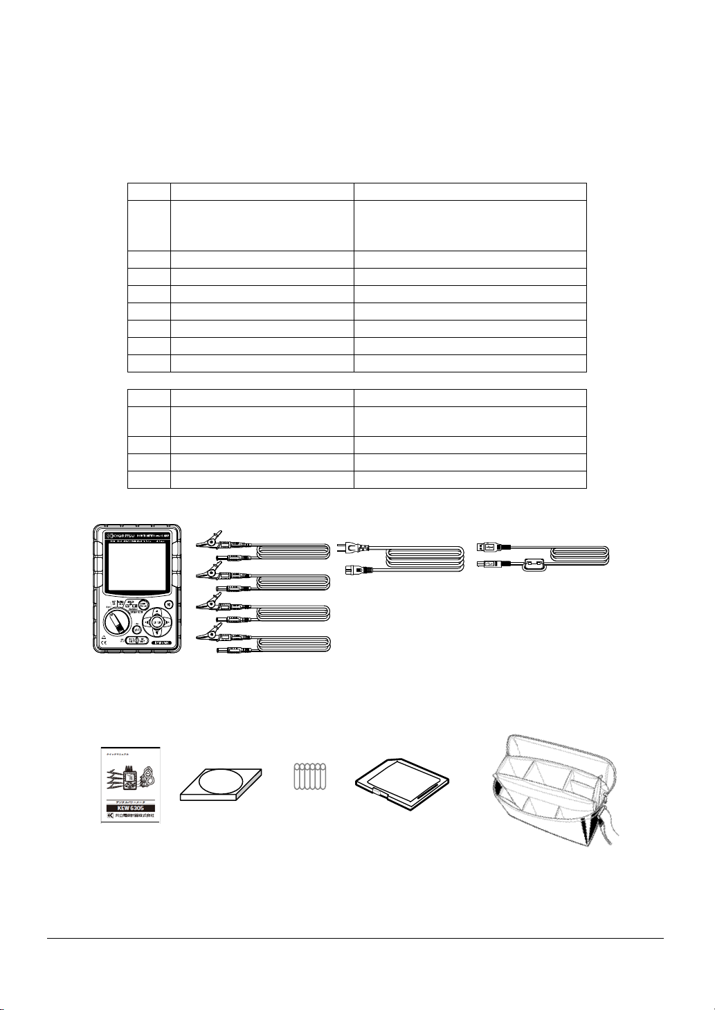
● Unpacking procedure
We thank you for purchasing our digital Power Meter KEW6305. Please check the contents and
instrument before us
e.
● Items listed below are included with the standard set:
1 Main unit KEW6305: 1 unit
MODEL7141B:1 set
Voltage test lead
2
3 Power cord MODEL7170: 1 pce
4 USB cord MODEL7148: 1 pce
5 Quick manual 1 pce
6 CD-ROM 1 pce
7 Battery Alkaline size AA battery (LR6): 6pcs
8 SD Card 1 pce
9 Carrying case MODEL9125: 1 pce
Optional parts
10 Clamp sensor Depending on model purchased
Instruction manual for
11
Clamp sensor
12 SD Card 2GB
13 Carrying case for Main unit MODEL9132
14 Power supply adapter MODEL8312
1. Main unit 2. Voltage test lead 3. Power cord 4. USB cord
(RED, GREEN, BLUE, BLACK: 1 pce
for each)
1 pce
Quick 6.CD-ROM 7. Battery 8. SD Card 9. Carrying case
5.
manual
1 KEW6305
Page 3
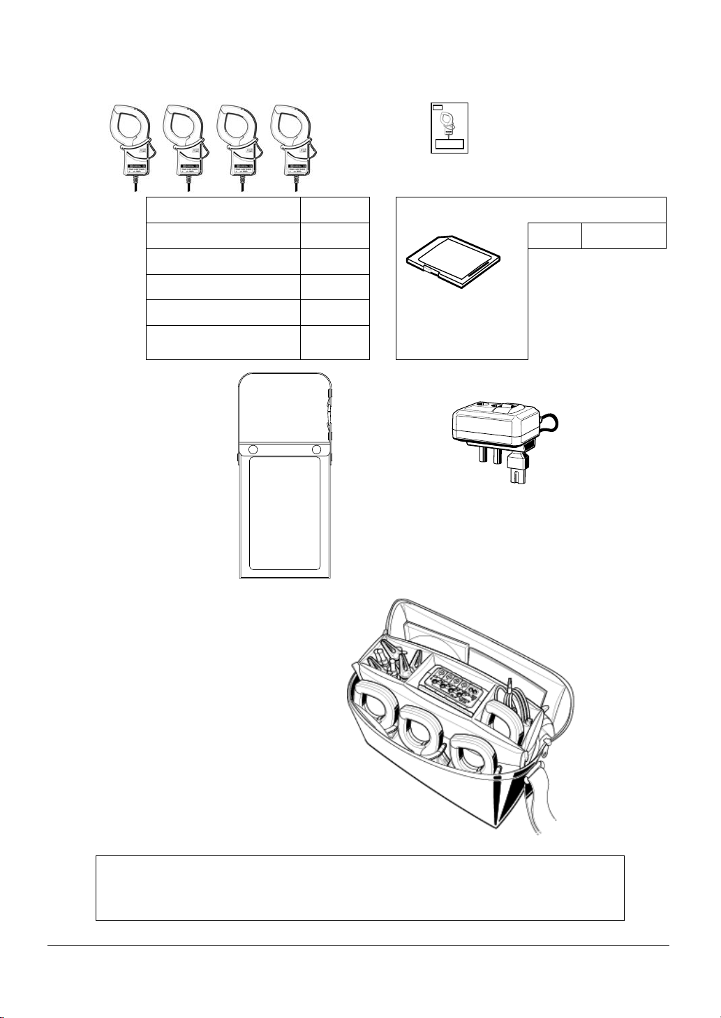
10. Clamp sensor 11. Instruction manual for Clamp sensor
(depending on model purchased)
50A type (Φ24mm) M-8128
100A type (Φ24mm) M-8127
200A type (Φ40mm) M-8126
500A type (Φ40mm) M-8125
1000A type (Φ68mm) M-8124
3000A type
(Φ150mm)
13. Carrying case for 14. Power supply adapter
main unit (with magnet)
M-8129
12. SD Card
● Storage
Store the items as shown below after use.
2GB M-8326-02
● In case any of the items listed above are found to be damaged or missing or if
the
printing is unclear, please contact your local KYORITSU distributor.
KEW6305
2
Page 4
● Safety warnings
This instrument has been designed, manufactured and tested according to IEC 61010-1: Safety
requirements for Electronic Measuring apparatus, and delivered in the best condition after passing
quality control tests.
This instruction manual contains warnings and safety procedures which have to be
observed by the user to ensure safe operation of the instrument and to maint ain it in safe
condition. Therefore, read through these operating instructions before using the
instrument.
WARNING
- For about Instruction manual -
● Read through and understand the instructions contained in this manual before using the
instrument.
● Keep the manual at hand to enable quick reference whenever necessary.
● The instrument is to be used only in its intended applications.
● Understand and follow all the safety instructions contained in the manual.
● Read the enclosed Quick manual after reading this instruction manual.
● As to the Clamp sensor use, refer to the instruction manual supplied with the sensor.
It is essential that the above instructions are adhered to. Failure to follow the above instructions
may cause injury, instrument damage and/or damage to equipment under test.
The symbol indicated on the instrument, means that the user must refer to the related parts in
the manual for safe operation of the instrument. It is essential to read the instructions wherever the
symbol appears in the manual.
DANGER : is reserved for conditions and actions that are likely to cause serious or fatal injury.
WARNING : is reserved for conditions and actions that can cause serious or fatal injury.
CAUTION
: is reserved for conditions and actions that can cause injury or instrument damage.
3 KEW6305
Page 5
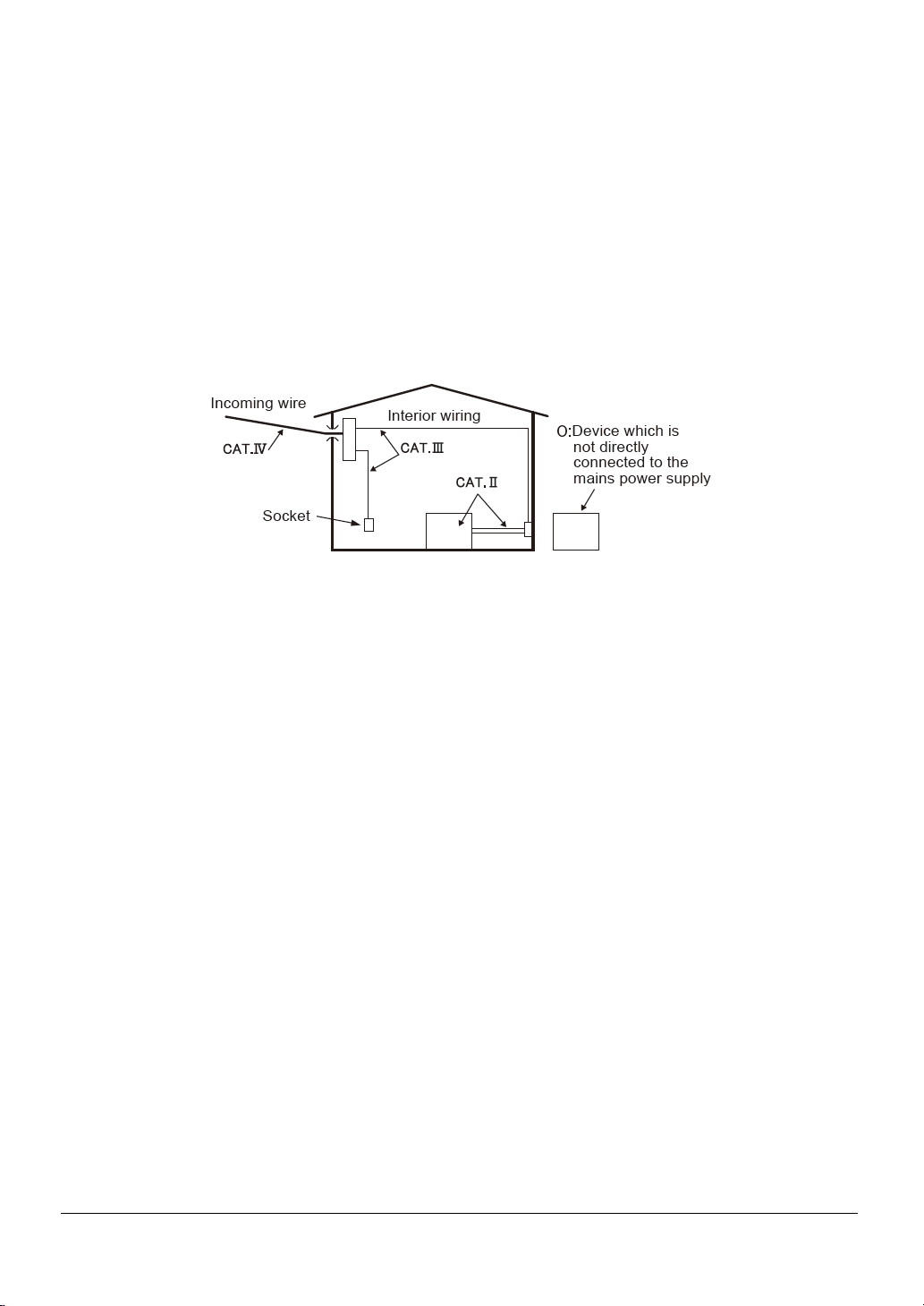
O Measurement Category
To ensure safe operation of measuring instruments, IEC 61010 establishes safety standards for
various electrical environments, categorized as O to CAT.IV, and called measurement categories.
Higher-numbered categories correspond to electrical environments with greater momentary
energy,
so a measuring instrument designed for CAT.III environments can endure greater momentary
energy
than one designed for CAT.II.
O : Circuits which are not directly connected to the mains power supply.
CAT.II : Electrical circuits of equipment connected to an AC electrical outlet by a power cord.
CAT.III : Primary electrical circuits of the equipment connected directly to the distribution panel,
and feeders from the distribution panel to outlets.
CAT.IV : The circuit from the service drop to the service entrance, and to the power meter and
primary overcurrent protection device (distribution panel).
KEW6305
4
Page 6

DANGER
● Verify proper operation on a known source before use.
● Verify proper operation on a known source before taking action as a result of the indication of
the instrument.
● Never make measurement on a circuit in which the electrical potential exceeds 600VAC.
● Do not attempt to make measurement in the presence of flammable gasses. Otherwise, the use
of the instrument may cause sparking, which can lead to an explosion.
● Never attempt to use the instrument if its surface or your hand is wet.
- Measurement -
● Do not exceed the maximum allowable input of any measuring range.
● Never open the Battery cover during a measurement.
- Battery -
● Do not try to replace batteries during a measurement.
● Brand and type of the batteries to be used should be harmonized.
- Power cord -
● Connect the Power cord mains plug to a mains socket outlet.
● Use only the Power cord supplied with this instrument.
- Power supply connector -
● Never touch the Power supply connector although it is insulated while the instrument is
operating
with batteries.
- Voltage test leads -
● Use only the ones supplied with this instrument.
● Confirm that the measured voltage rating of the test lead is not exceeded.
● Do not connect a Voltage test lead unless required for measuring the parameters desired.
● Connect Voltage test leads to the instrument first, and only then connect them to the circuit
under
test.
● Never disconnect Voltage test leads while the instrument is in use.
● Connect to the downstream side of a circuit breaker since a current capacity at the upstream
side
is large.
● Do not touch two lines under test with the metal tips of the test leads.
● Never touch the metal tips of the test leads.
- Clamp sensor -
● Use only the ones dedicated for this instrument.
● Confirm that the measured current rating of the test lead is not exceeded.
● Do not connect a Camp sensor unless required for measuring the parameters desired.
● Connect sensors to the instrument first, and only then connect them to the circuit under test.
● Never disconnect sensors while the instrument is in use.
● Connect to the downstream side of a circuit breaker since a current capacity at the upstream
side
is large.
● Do not touch two lines under test with the metal tips of the test leads.
5 KEW6305
Page 7

WARNING
- Connection -
● Confirm that the instrument is off, and then connect the Power cord.
● Connect the Power cord, Voltage test leads and Clamp sensors to the instrument first. Cord to
be firmly inserted.
● Never attempt to make any measurement if any abnormal conditions, such as a broken cover
or exposed metal parts are present on the Instrument, Voltage test leads, Power cord and
Clamp
sensor.
- Measurement –
● Ensure that the Current input terminal cover, USB connector cover and SD card connector cover
are closed when not in use during a measurement.
- Not in use for a long period -
● Remove the Power cord from the outlet if the instrument will not be in use for a long period.
- Repair/ Calibration -
● Do not install substitute parts or make any modification to the instrument. Return the instrument
to your local KYORITSU distributor for repair or re-calibration in case of suspected faulty
operation.
- Battery -
● Do not try to replace the batteries if the surface of the instrument is wet.
● Ensure that the Power cord, Voltage test leads and Clamp sensor are removed from the
instrument, and that the instrument is switched off when opening the Battery cover for battery
replacement.
● Never mix new and old batteries.
● Install batteries in correct polarity as marked inside the Battery compartment area.
- Power cord -
● Do not use the damaged cord.
● Don’t put heavy things on, step on or pinch the cord, moreover, not to touch any heating
material.
● When unplugging the cord from the mains socket outlet, do so by removing the plug first and not
by pulling the Power cord.
- Measures against abnormal symptoms -
● If the instrument begins to emit smoke, becomes too hot, or gives off an unusual smell,
immediately power it off and disconnect the power cord from the outlet. Also power off the power
to the object under test. If any anomalies as noted, contact your local KYORITSU distributor.
- Use of protective gears -
● Use insulated gloves, boots or head gears at measurements to ensure user’s safety.
KEW6305
6
Page 8
CAUTION
● Caution should be taken since conductors under test may be hot.
● Never apply currents or voltages exceeding the maximum allowable input for the instrument for a
long time.
● Do not apply currents or voltages for the Voltage test leads or Clamp sensors while the instrument
is off.
● Don’t use the instrument at dusty places or to be spattered.
● Don’t use the instrument under a strong electric storm or in the vicinity of energized object.
● Never give strong vibrations or drop shocks.
● While using a SD card, do not replace or remove the card. ( symbol blinks while accessing
SD card.)
Otherwise, the saved data in the card may be lost or the instrument may be damaged.
- Clamp sensor -
● Do not bend or pull the cable of the Clamp sensor.
- Treatm ent after use -
● Power off the instrument and disconnect the Power cord, Voltage test leads and Clamp sensors
from the
instrument.
● Remove the batteries if the instrument is to be stored and will not be in use for a long period.
● Remove the SD card when carrying the instrument.
● Never give strong vibrations or drop shocks when carrying the instrument.
● Do not expose the instrument to direct sunlight, high temperatures, humidity or dew.
● Use a damp cloth with neutral detergent or water for cleaning the instrument. Do not use
abrasives or solvents.
● Do not store the instrument if it is wet.
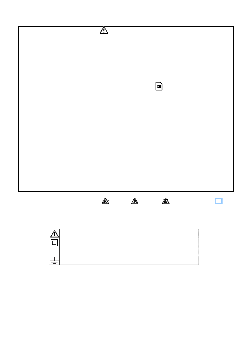
Carefully read and follow the instructions: DANGER, WARNING, CAUTION and
NOTE ( )
described in each section.
The following symbols are used in this manual:
User must refer to the explanations in the instruction manual.
Instrument with double or reinforced insulation
AC
~
(Functional) Earth terminal
7 KEW6305
Page 9

KEW6305
8
Page 10
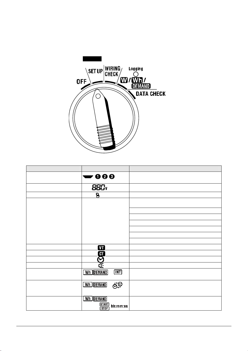
K
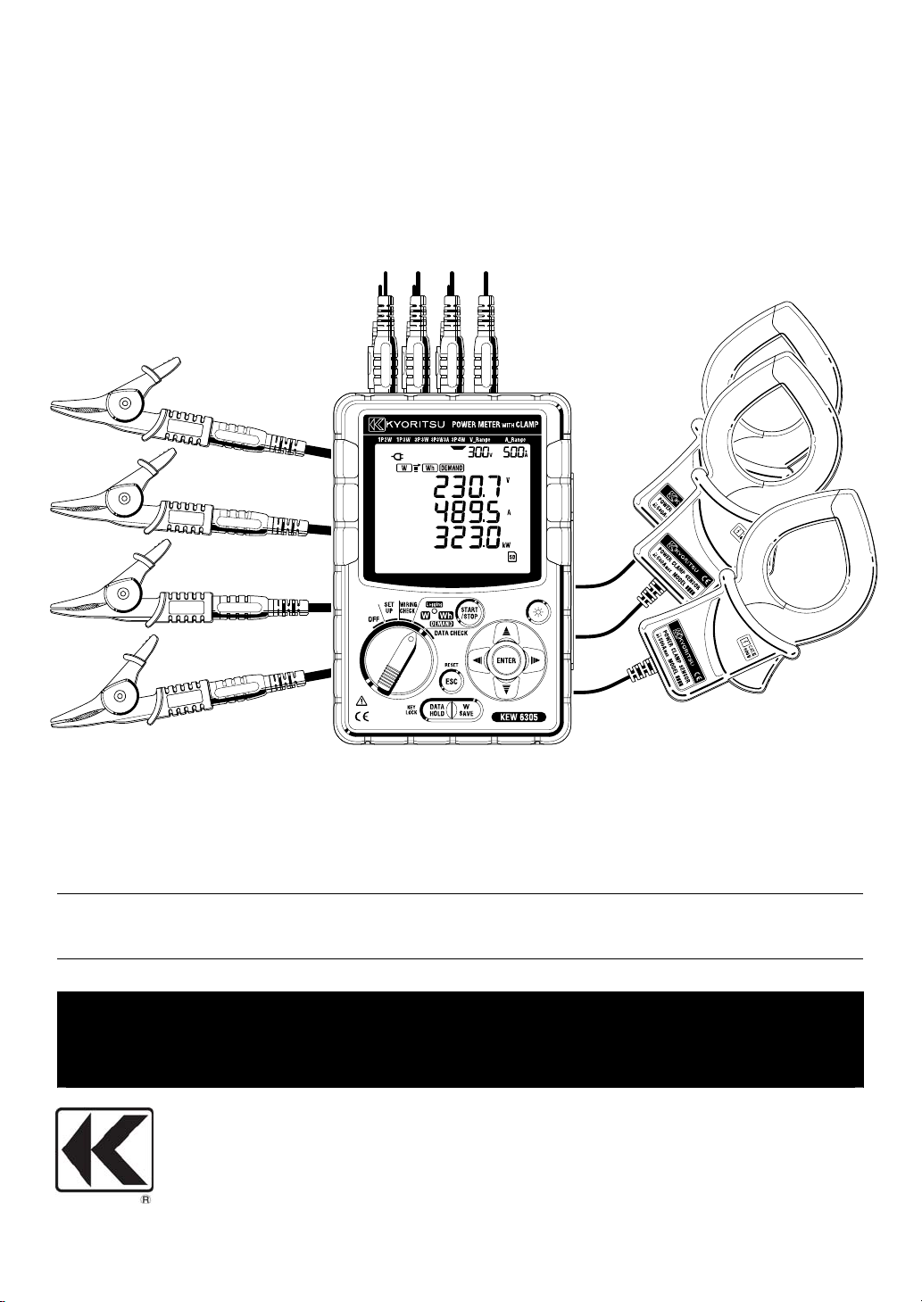
1. Instrument Overview
1.1 Functional Overview
SET UP
Make settings for KEW6305 or for
measurements.
See “Setting (Section 4)” for further details.
WIRING CHEC
Check the connections and display the
results.
See “Wiring check (Section 10)” for further
details.
1.1 KEW6305
Page 11
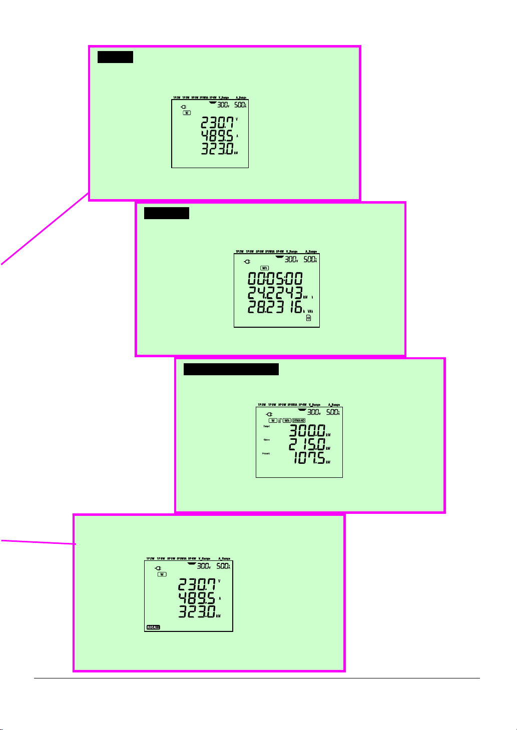
_W_
_
_
_
K
Instant aneous value measurement
Measure/ display the instantaneous values of current,
voltage and electric power.
See “Instantaneous value Measurement (Section 6)” for
further details.
Wh_
Display/ record active/ apparent/ reactive energies, and
record the average/ max/ min values of measured
instantaneous values.
See “Integration value Me asurement (Section 7)” for further
details.
Integration value measurement
DEMAND
Display/ record demand values based on the preset target
values.
See “Demand Measurement (Section 8)” for further details.
Demand measurement
DA TA CHEC
Recall and show the saved data on the LCD.
See “Saved data (Section 10)” for further details.
KEW6305
1.2
Page 12

1.2 Features
This is a digital Power Clamp Meter that can be used for various wiring systems. Measured data can be
saved either in the internal memory or SD card, and can be transmitted to PC via USB connection or by
using SD card reader.
Safety Construction
Designed to meet the international safety standard IEC 61010-1 CAT.III 600V.
Wiring configuration
KEW6305 supports: Single-phase 2-wire, Single-phase 3-wire, Three-phase 3-wire, Three-phase
4-wire.
Measurement and calculation
KEW6305 measures voltage (RMS), current (RMS), active power, frequency and calculates reactive/
apparent power, power factor, neutral current and active/ reactive/ apparent energy.
Demand measurement
Electricity consumption can be easily monitored so as not to exceed the target maximum demand
values.
Saving data
KEW6305 is endowed with a logging function with a preset recording interval. Data can be saved by
manual operation or at pre-set time & date.
Dual power supply system
KEW6305 operates either with an AC power supply or with batteries. Both dry-cell batteries (alkaline)
and rechargeable batteries (Ni-MH) can be used. In the event of an interruption, while operating with
an AC power supply, power to the instrument is automatically restored by the batteries in the instrument.
Large display
Up to 3 measured items can be displayed on the large screen simultaneously.
Light & compact design
Clamp sensor type, compact and light weight design
Application
Data in the internal memory and in SD card can be transmitted to PC using USB connection or SD
slot. The supplied PC software application enables easy settings of the instrument and analysis of
the saved data from PC.
1.3 KEW6305
Page 13
1.3 Measuring Procedure
● Steps for measurement
* Measuring instantaneous values :
“Section 6: Instantaneous v alue Measurement”
* Measuring integration values:
“Section 7: Integration value Measureme nt”
* Measuring demand values:
“Section 8: Demand Measu rement”
Ensuring your safety
See “Safety warnings”.
Preparation
See “Section 3: Getting started”.
Basic / Measurement / Save Settings
See “Section 4: Setting”.
Wiring
See “Section 5: Wiring”.
KEW6305
1.4
Page 14

1.4 Outline of max demand measurement concept
In some countries, large consumers of electricity will usually have a maximum demand contract with
the power company. Such contract varies from country to country. The following is an explanation of
a typical Japanese maximum demand contract.
● Maximum Demand contract
In such a contract the electricity tariff rates (i.e. for kWhr units) are based upon the consumer’s
maximum power demand. The maximum demand is the maximum of average powers recorded
over a 30min intervals.
This is measured by the maximum demand meter belonging to the power company. Let’s assume
that a power company has the following applicable rates.
$2 per KWhr unit for a recorded max demand 300KW during a year
$4 per KWhr unit for a recorded max demand 500KW during a year
$5 per KWhr unit for a recorded max demand 600KW during a year
Assuming that the consumer is on the 500kW/year rate (ie. $4), and the recorded max demand
during a particular day(say 15th January) is 600kW . Then the new applicable rate from 1st
February onwards will be the 600kW/year rate (ie. $5) for the next 365 days. If a year later, on
February 1st the recorded maximum demand is 300kW, then the new applicable rates will be
changed to 300kW/year rate (i.e. $2) for the subsequent 365 days. However if during this period,
the max demand goes up again, and say 600kW is recorded on 15th March, the applicable rates
change again to the 600kW/year rate (i.e.$5) for the subsequent 365 days.
● Benefits of maximum demand control
It is thus important for consumers with such contracts to monitor closely fluctuations in their power
demand to ensure that their max demand limits are not exceeded and thus incur higher tariffs.
Maximum Demand control is more effective in countries with higher electricity tariffs.
● Status of maximum demand contract
In the past, in Japan, only consumers whose electricity supply was rated at 600kW or more used to
enter into a demand contract. However, nowadays power companies install maximum demand
meters at all consumers whose supply is rated 70kW or more.
● Maximum Demand measurement limitations
N.B. The readings from power company maximum demand meter and from the 6300 will not match
completely due to an obvious time-lag difference in the start of the integration period (eg.30mins)
over which the max demand is taken.
1.5 KEW6305
Page 15

KEW6305
1.6
Page 16
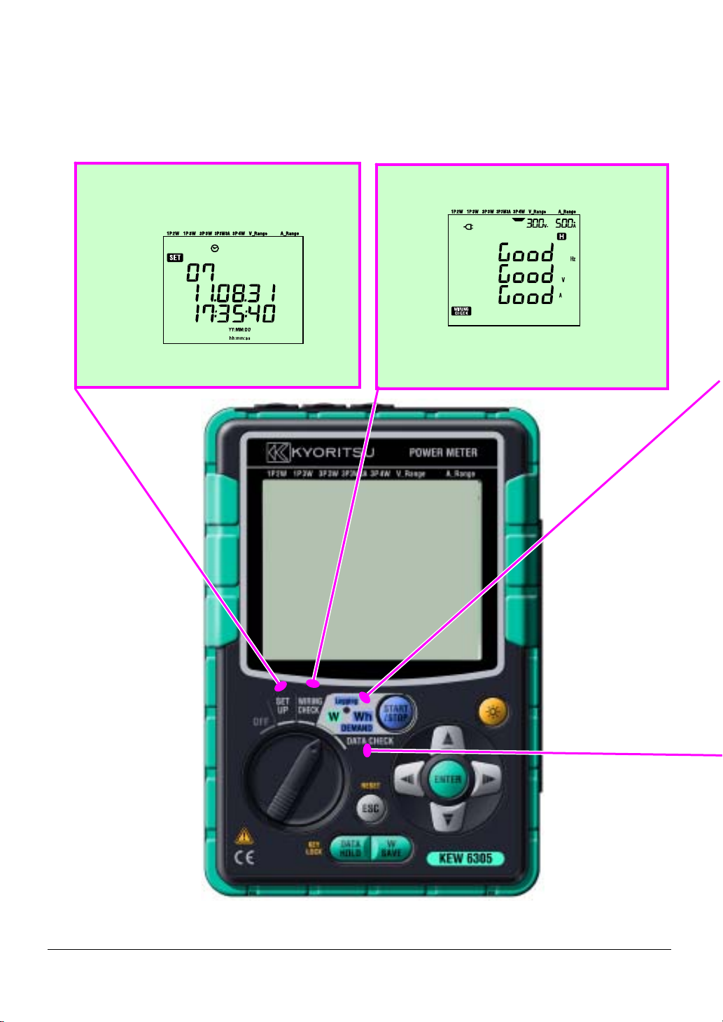
2. Instrument Layout
2.1 Front view
Display (LCD) / Keys
Display (LCD)
LED status indicator
Green lights up : Recording & measuring
Green blinks : Stand-by mode (lights up when preset rec. start time comes)
Red blinks : Charging batteries
Keys
2.1 KEW6305
Page 17
Key functions
LED status indicator
Green lights up :
Recording &
measuring
Green blinks :
Stand-by mode
Red lights up :
Recording error
Function switch:
Power on KEW6305. (Rotate to any position other than “OFF”.)
Keys Details
STAR T/STOP
Key
Backlight Key Turn on/ off th e LCD backlight.
Start/ stop integration and demand measurement.
Cursor Key
On measurement screen: switch screens, and
on setting screen: select setting items or change
values or digits
ENTER Key Confirm entries.
ESC Key
DA TA HOLD Key
SA VE Key Save the measured instantaneous values.
* Cancel setting changes,
* Clear integration / demand values.
* Data hold
* Key lock
A long press (2 sec or longer) locks Keys and
another long press (2 sec or longer) unlocks the
locked Keys.
KEW6305 2.2
Page 18
2.2 LCD indications
< All symbol s to be displayed on the LCD >
Wiring system
Volt age range
Current range
Phase
number
Unit
2.3 KEW6305
Page 19
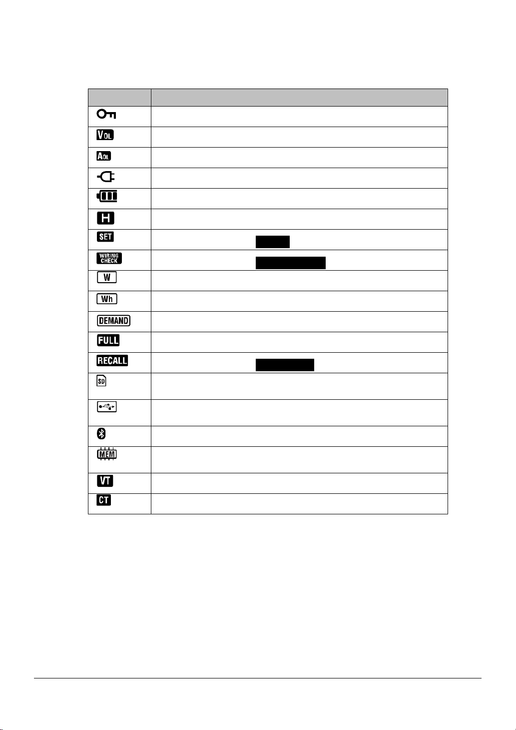
< Symbols indicate the functions or status during measurement >
Symbols Functions and status during measurement
Light s up when the keys are locked.
Lights up when voltage excee ds a certain condition.
Lights up when current exceeds a certai n condition.
Lights up when instruments is wo rking by AC power supply.
Lights up when instruments is wo rking by batteries.
Lights up when data hold function is activated.
Light s up when selecting SET UP Range.
Light s up when selecting WIRING CHECK Range.
Blinks while inst antaneous values are being displayed on the LCD.
Blinks while int egration values are being displayed on the LCD.
Blinks while de mand values are being displayed on the LCD.
When the capacity of SD card or internal memory is exceeded.
Light s up when selecting DA T A CHECK Range.
Lights up while data can be sa ved in the SD card, and blinks while
saving data.
Lights up while a USB cord is connected to the terminal, and blinks
during data communication.
Light s up while using Bluetooth co mmunication.
Lights up while data can be sa ved in the internal memory , and blinks
while accessing to the memory .
Light s up when VT ratio is set t o other than “1”.
Light s up when CT ratio is set t o other than “1”.
KEW6305 2.4
Page 20
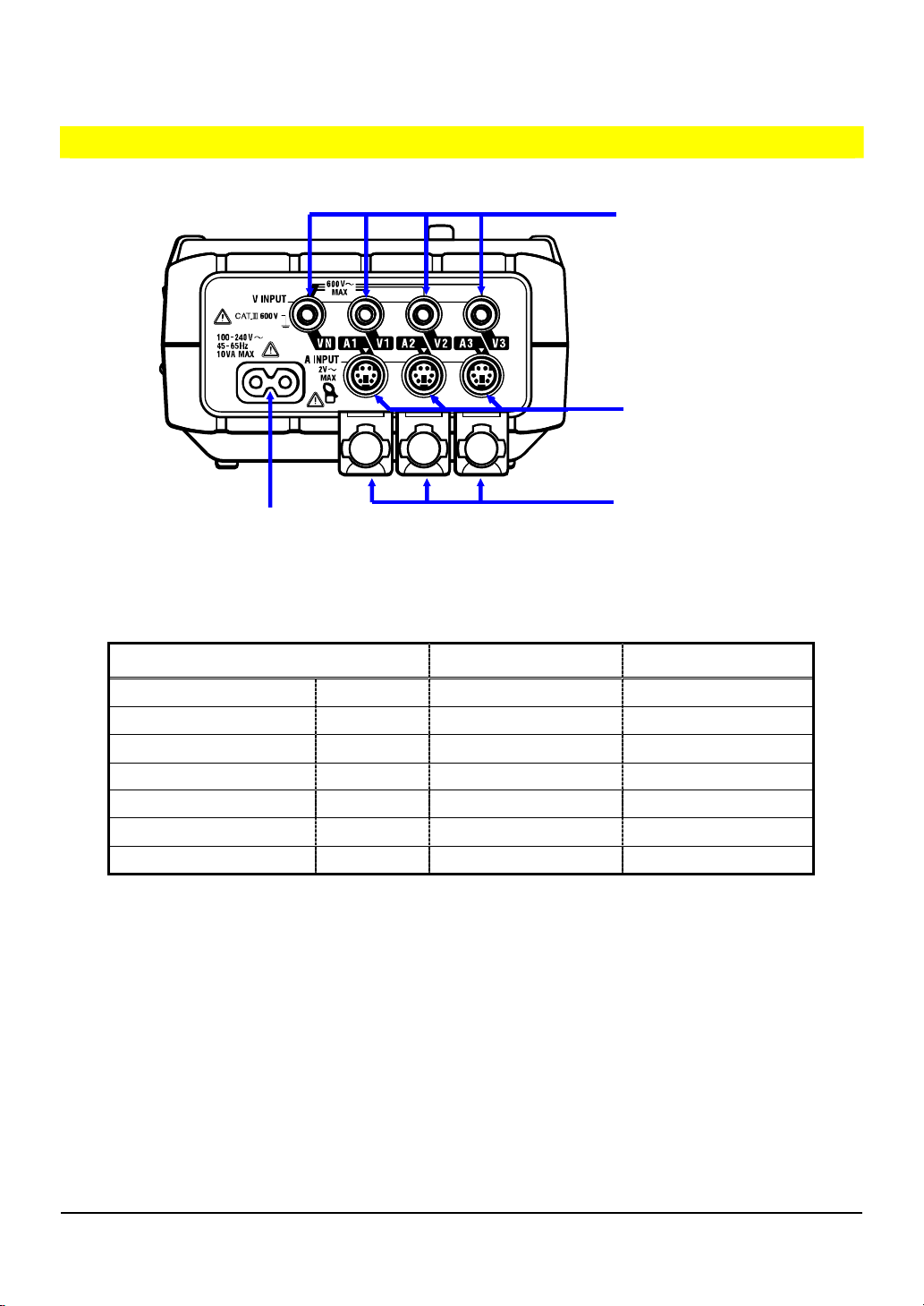
2.3 Connector
Descriptions
Volt age Input Terminal
(VN, V1, V2, V3)
Current Input Terminal
(A1, A2, A3,)
Power Connector
Terminal Cover
Wiring configuration Volt age Input Terminal Current Input T erminal
Single-phase 2-wire
Single-phase 2-wire (2ch)
Single-phase 2-wire (3ch)
Single-phase 3-wire
Three-phase 3-wire
Three-phase 3-wire 3A
Three-phase 4-wire
1P2W(1ch)
1P2W(2ch)
1P2W(3ch)
1P3W
3P3W
3P3W3A
3P4W
VN, 1 A1
VN, 1 A1, 2
VN, 1 A1, 2, 3
VN, 1, 2 A1, 2
VN, 1, 2 A1, 2
V1, 2, 3 A1, 2, 3
VN, 1, 2, 3 A1, 2, 3
2.5 KEW6305
Page 21
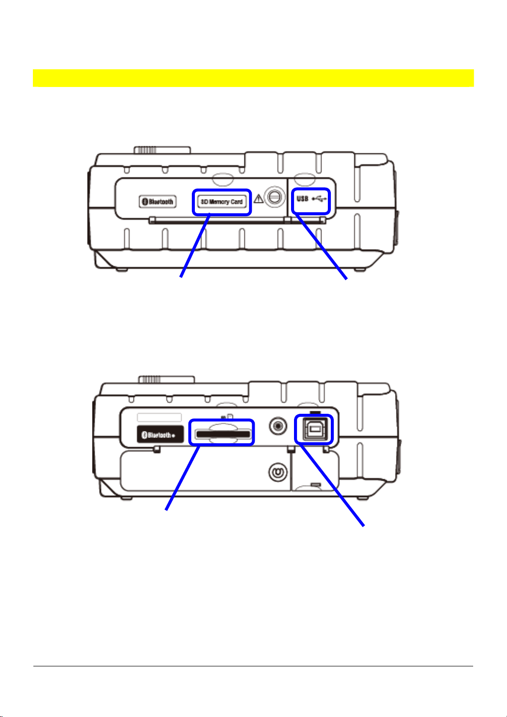
2.4 Side face
Descriptions
< When the Connector cover is closed. >
SD Card Cover
USB Port Cover
< When the Connector cover is opened. >
SD Card Slot
USB Port
KEW6305 2.6
Page 22
3. Getting started
3.1 Power Supply
3.1.1 Battery
KEW6305 operates with either an AC power supply or batteries.
Capable of performing measurements in the event of AC power interruption, power to the instrument
is automatically restored by the batteries installed in the instrument. Dry-cell batteries (alkaline) and
rechargeable batteries (Ni-MH) can be both used.
* Dry-cell batteries (alkaline) are supplied as accessories.
DANGER
● Never open the Battery Cover during a measurement.
● Brand and type of the batteries to be used should be harmonized.
● Never touch the Power supply connector although it is insulated while the instrument is operating with
batteries.
● Ensure that the Power cord, Voltage test leads and Clamp sensor are removed from the instrument,
and that the instrument is switched off when opening the Battery cover for battery replacement.
WARNING
CAUTION
● Never mix new and old batteries.
● Install batteries in correct polarity as marked inside the Battery compartment area.
Batteries are not in the instrument at the time of purchase. Please insert the supplied batteries before
starting to use the instrument. Battery power is consumed even if the instrument is being off. Remove all
the batteries if the instrument is to be stored and will not be in use for a long period.
When the instrument is powered by an AC power supply, it doesn’t operate with batteries.
If an AC supply is interrupted and the batteries have not been inserted,
and all data may lost.
the instrument goes off
3.1 KEW6305
Page 23
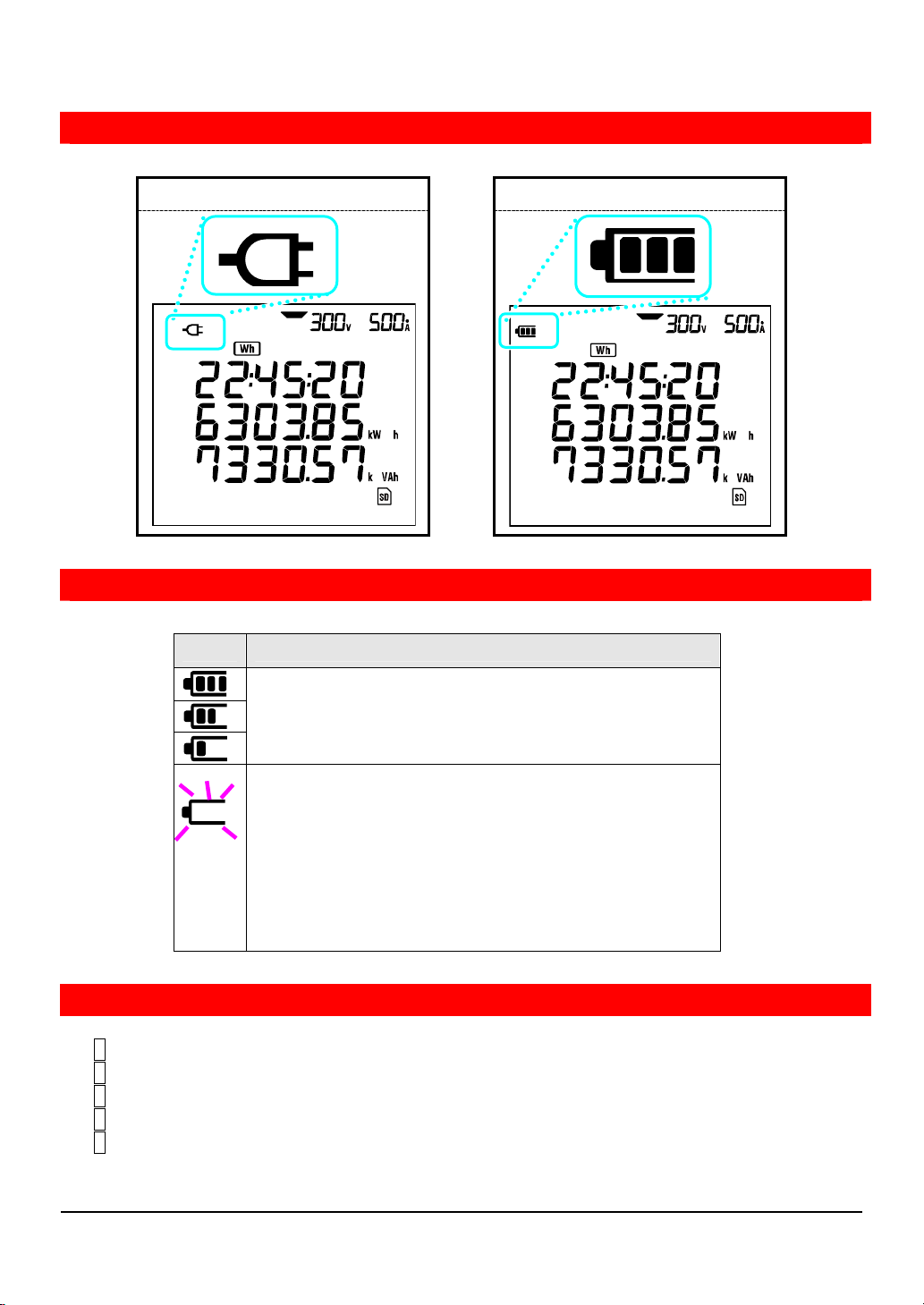
Power supply indicator
Symbol of power supply changes as follows.
AC power supply-operated Battery-operated
Battery condition
Battery symbol varies as follows according to the battery condition.
Battery operating time
For approx. 15 hours, with new alkaline batteries.
* It is reference time and will be shortened if using the
backlight or Bluetooth function.
(blink)
Batteries are exhausted.
(Accuracy of readings cannot be guaranteed.)
Depending on the states of measurement, instrument
operates as follows automatically.
* while saving instantaneous value data (Files are opened.)
-> Close the open files. (Data will be saved.)
* while measuring integration/ demand values
-> Force-quit measurements. (Data will be saved.)
Inserting dry-cell batteries
1 Loosen two Battery Cover-fixing screws and remove the Cover.
2 Take out all the batteries.
3 Insert batteries (LR6 : size AA alkaline batteries) in correct polarity.
4 Install the Battery Cover and tighten two screws.
5 Connect the AC Power Cord and power on the instrument.
KEW6305 3.2
Page 24
3.1.2 AC Power supply
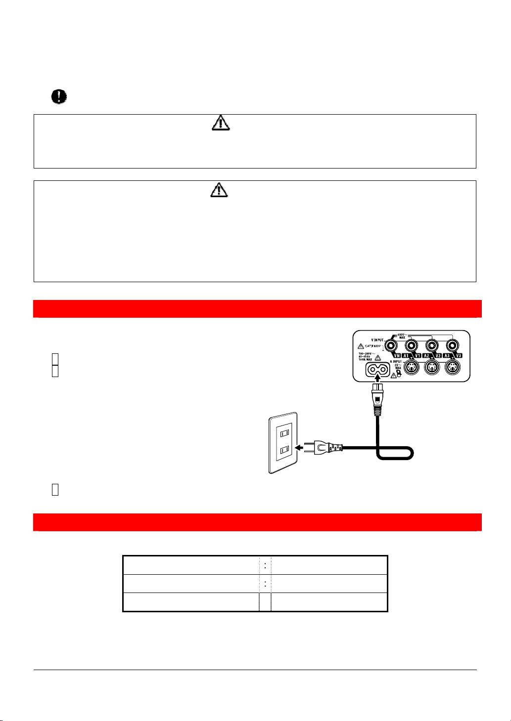
Check the followings before connecting the Power cord.
DANGER
● Use only the Power cord supplied with this instrument.
● Connect the Power cord mains plug to a mains socket outlet. The mains supply voltage must not
exceed AC240V. (max rated voltage of supplied Power cord MODEL7169 : AC125V)
WARNING
● Confirm that the instrument is powered off, and then connect the Power cord.
● Connect the Power cord to the instrument first. Cord to be firmly inserted.
● Never attempt to make measurement if any abnormal conditions such as abnormal conditions are
noted, such as a broken Cover and exposed metal parts.
● When the instrument is not in use, disconnect the Power cord from the outlet.
● When unplugging the cord from the mains socket outlet, do so by removing the plug first and not by
pulling the cord.
Power cord connection
Follow the procedure below, and connect the Power cord.
1 Confirm that the instrument is powered off.
2 Connect the Power cord to the Power connector on the instrument.
3 Connect the Power cord plug to the mains socket outlet.
Power supply rating
Rating of power supply is as follows.
Rated supply voltage : 100 to 240V AC (±10%)
Rated power supply frequency : 45 to 65Hz
Max power consumption : 10VA max
3.3 KEW6305
Page 25
3.2 Voltage test leads and Clamp sensor connection
Check the followings before connecting the test leads and sensors.
DANGER
● Use only the Voltage test leads supplied with this instrument.
● Use the dedicated Clamp sensor for this instrument, and confirm that the measured current rating of the
Clamp sensor is not exceeded.
● Do not connect all the Voltage test leads or Clamp sensors unless required for measuring the
parameters desired.
● Connect the test leads and sensors to the instrument first, and only then connect them to the circuit
under test.
● Never disconnect the Voltage test leads and sensors while the instrument is in use.
WARNING
● Confirm that the instrument is powered off, and then connect the Power cord.
● Connect the Power cord to the instrument first. Cord to be firmly inserted.
● Never attempt to make measurement if any abnormal conditions such as abnormal conditions are
noted, such as a broken Cover and exposed metal parts.
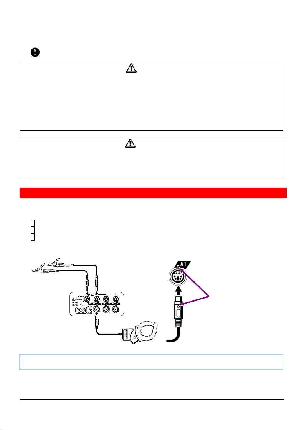
V olt age test leads and Clamp sensor connection
Follow the procedure below, and connect the Voltage test leads and Clamp sensors.
1 Confirm that the instrument is powered off.
2 Connect the appropriate Voltage test leads to the Voltage input terminal on the instrument.
3 Connect the appropriate Clamp sensors to the Current input terminal on the instrument.
Match the direction of the arrow mark indicated on the output terminal of the clamp sensor and
the mark on the Current input terminal on the instrument.
Number of Voltage test leads and Clamp sensors to be used will be different depending on the wiring
configuration under test. For further details, refer to “5.2 Basic Wiring Configuration” in this manual.
Match the arrow marks.
KEW6305 3.4
Page 26
3.3 Start KEW6305
3.3.1 Start-up Screen
KEW6305 gets started when rotating and setting the Function switch to any position other than “OFF”
position. Then, the Start-up screen will be displayed.
1 All the segments will be displayed for about 1 sec., and then MODEL/VERSION info will be
displayed for about 1 sec..
2 A screen corresponded to the selected range will be displayed.
All segments to be displayed
Model name/ Version info.
3.5 KEW6305
Page 27
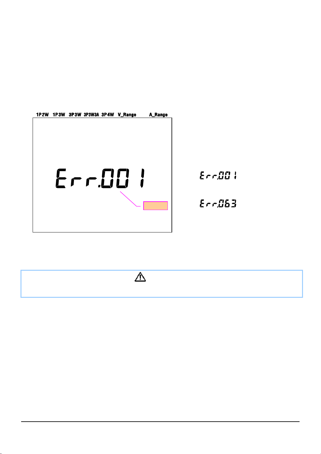
3.3.2 Error message
This instrument automatically checks the internal circuit immediately after it is turned on.
When a failure in the internal circuit is suspected, the error screen below will be displayed for about
2 sec. prior to the start-up screen.
In case that following screen appears, stop using the instrument immediately and refer to “Section12:
When defect or breakdown is suspected” in this manual.
Error No.
Error number (001 - 063)
~
CAUTION
Measurement can be done if the error screen appeared when powering on the instrument. However, the
accuracy of the measured value may out of the specification.
KEW6305 3.6
Page 28
4. Setting
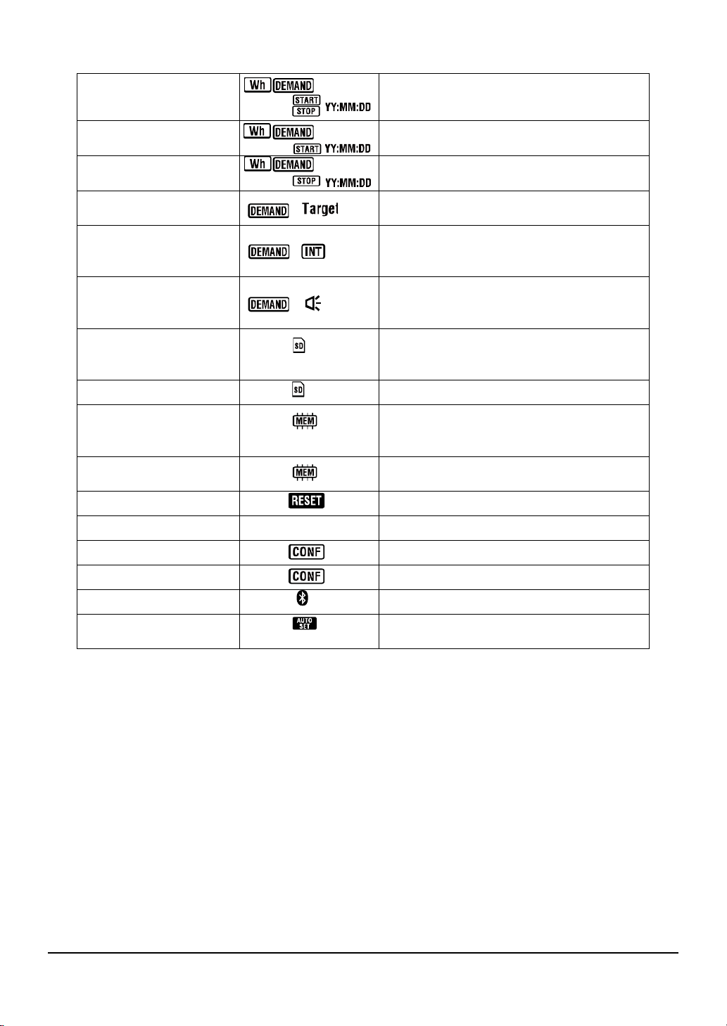
4.1 List of setting items
This section deals with settings for measurement and data saving.
Set the Function switch to SET UP range as follows.
Setting no./ item Symbol Details
Wiring system
01
02 Voltage range
1P2W(1ch)/ 1P2W(2ch)/ 1P2W(3ch)
/ 1P3W/ 3P3W/ 3P3W3A/ 3P4W
150/ 300/ 600V
03 Clamp sensor 50/ 100/ 200/ 500/ 1000/ 3000A type
03
Sensor
Range
50A 1/5/10/25/50A/AUTO
Current range -
04
100A 2/10/20/50/100A/AUTO
200A 4/20/40/100/200A/AUTO
500A 10/50/100/250/500A/AUTO
1000A 20/100/200/500/1000A/AUTO
3000A 300/1000/3000A
05 VT ratio
06 CT ratio
0.01 - 9999.99 (can be set by 0.01)
0.01 - 9999.99 (can be set by 0.01)
07 Date and time Year:Month:Day:Hour:Minute:Second
08 Buzzer ON / OFF
Recording
09
interval
Specific time period
10
rec. or endless rec.
Time period setting
11*1
Time setting
1/ 2/ 5/ 10/ 15/ 20/ 30 sec./
+
1/ 2/ 5/ 10/ 15/ 20/ 30 min ./ 1 hour
+
ON: Specifying st art/ stop time
(repeatedly recorded)
OFF : Record the data continuously
+
Start and stop time
(
Y ear:Month :Day:Hour:Minute :Second
)
4.1 KEW6305
Page 29
Time period setting
*1
12
13*2
14*2
Date setting
St art of continuous
measurement
End of continuous
measurement
15 Target demand
Demand
16
measurement cycle
Demand
17
warning
cycle
Available space
18
in
SD card
19 SD card Forma t
Available space
20
in
Internal memory
Internal memory
21
Format
22 System reset
+
+
+
Value : 0.1 - 999.9
+
Y ear:Month :Day:Hour:Minute :Second
Year:Month:Day:Hour:Minu te:Second
Year:Month:Day:Hour:Minu te:Second
Unit: W/kW/MW/GW/V A/kVA/MVA/GVA
NO/ 10/ 15/ 30 min
+
* Demand measurement will not be performed
when “NO” has been selected.
+
1/2/5 min. when measurement cycle is 10or15
min., 1/2/5/10/15 min. when measurement cycle
is 30 min.
Show the available space in the inst alled SD
card in percentage.
ON(Format)/ OFF(Not format)
Show the available space in the inter nal
memory in percentage.
ON(Format)/ OFF(Not format)
ON(Reset)/ OFF(Not reset)
23 ID number 24 Setting read
25 Setting save
26 Bluetooth
V/A Range
27
Auto-setting
Designate ID no. (00-001 - 99-999)
Save no.: 01 - 20
Save no.: 01 - 20
ON/ OFF
ON/ OFF
*1 : Setting 11& 12 can be changed only when Setting 10 has been set to “ON”.
*2 : Setting 13& 14 can be changed only when Setting 10 has been set to “OFF”.
KEW6305 4.2
Page 30
4.2 Setting procedure of each setting item
“ Setting 01” Wiring system
Following explains how to make settings for wiring system.
Select the appropriate wiring system according to the environment to be measured.
1P2W(1ch) : Single-phase 2-wire (1ch)
1P2W(2ch) : Single-phase 2-wire (2ch)
1P2W(3ch) : Single-phase 2-wire (3ch)
Setting item
Default value (or after system re set) 3P3 W
* T wo-wattmeter method should be used for measuring 3P3W that requires using two Clamp sensors.
* For measuring/ recording the voltage and current on each phase, select “3P3W3A” and use three
Clamp sensors.
1P3W : Single-phase 3-wire
3P3W : Three-phase 3-wire
3P3W3A : Three-phase 3-wire
3P4W : Three-phase 4-wire
1 Use th e Cursor key on the selection screen, and select “Setting 01”.
2 Press the ENTER key to get the instrument into setting change mode.
3 Present setting (or default value: 3P3W) blinks. Se lect the appropriate wiring configuration with the
Cursor key , and then press the ENTER key after making necessary change.
4.3 KEW6305
Page 31

“Setting 02” Voltage rang
Selecting a measurement range so that the estimated inputs will be close to the fu ll scale value is
recommended to obtain accurate results. Recommended range selections are: 150V range for rated
voltages between 100 - 120V , 300V range for 200 - 240V and 600V range for 400 – 440V.
Setting item 150V / 300V / 600V
Default value (or after system re set) 300V
1 Use th e Cursor key on the selection screen, and select “Setting 02”.
2 Press the ENTER key to get the instrument into setting change mode.
3 Present setting (or defau lt value: 300V) b links. Select the appropriate vo ltage range with the Cursor
key , and then press the ENTER key after making necessary change.
KEW6305 4.4
Page 32

“Setting 03” Clamp sensor
Selectable Current range (“Setting 04”) differs by the selected Clamp sensors.
Clamp sensor Current range (” Setting 04 ”)
50A (M-8128) 1 / 5 / 10 / 25 / 50A / AUTO
100A (M-8127) 2 / 10 / 20 / 50 / 100A / AU TO
200A (M-8126) 4 / 20 / 40 / 100 / 200A / AUTO
500A (M-8125) 10 / 50 / 100 / 250 / 500A / AUTO
1000A (M-8124) 20 / 100 / 200 / 500 / 1000A / AUTO
3000A 300 / 1000 / 3000A
Default value (or after system re set) 500A
1 Use th e Cursor key on the selection screen, and select “Setting 03”.
2 Press the ENTER key to get the instrument into setting change mode.
3 Present setting (or default value: 500A) blinks. Se lect the appropriate clamp sensor with the Cursor
key , and then press the ENTER key after making necessary change.
NOTE:
* Accurate results may not be obtained if the Clamp sensors in use do not match the sett ing
done for sensor.
4.5 KEW6305
Page 33

“Setting 04” Current range
Selectable Current range differs by clamp sensor selected at “Setting 03”.
Clamp sensor (“Se tting 0 3”) Current range
50A (M-8128) 1 / 5 / 10 / 25 / 50A / AUTO
100A (M-8127) 2 / 10 / 20 / 50 / 100A / AUTO
200A (M-8126) 4 / 20 / 40 / 100 / 200A / AUTO
500A (M-8125) 10 / 50 / 100 / 250 / 500A / AUTO
1000A (M-8124) 20 / 100 / 200 / 500 / 1000A / AUTO
3000A 300 / 1000 / 3000A
Default value (or after sy stem re set) AUTO
* Selecting “AUTO” activates auto-ranging function and the measuring range will be automatically
switched between the lowest and highest ranges.
1 Use th e Cursor key on the selection screen, and select “Setting 04”.
2 Press the ENTER key to get the instrument into setting change mode.
3 Present setting (or default value: AUTO) blinks. Select the appropriate current range with the Cursor
key , and then press the ENTER key after making necessary change.
NOTE:
* When a type of clamp sensor (“Setting 04”) is changed, current range may be changed to the
corresponding range automatically.
* Accurate results may not be obtained if the Clamp sensors in use do not match the setting done for
sensor.
* Using the auto-ranging function can measure wide range of input signals, however , accurate result s
may not be obtained when measuring loads that flactuate so widely within 1 sec..
KEW6305 4.6
Page 34

“Setting 05” VT ratio
For the detailed information about VT ratio, please refer to “5-3 VT/CT ratio” in this manual.
Setting range 0.01 - 9999.99
(can be set by 0.01)
Default value (or after system re set) 1.00
1 Use th e Cursor key on the selection screen, and select “Setting 05”.
2 Press the ENTER key to get the instrument into setting change mode.
3 The rightmost digit of previous setting (or default value: 1.00) blinks. Change number with the Cursor
key , and then press the ENTER key after making necessary change.
150V 300V 600V 1P2W 1P3W 3P3W 3P4W
5A 10A 20A 50A 100A 200A 500A 1000A
Function of Cursor keys:
To select the digit subject to cha nge.
To change the value of selected digit.
When VT ratio is set to other than 1, “
“ mark appears on the LCD.
NOTE
* When 0 is set as a VT ratio, it is forcefully changed to 1.
4.7 KEW6305
Page 35

“Setting 06” CT ratio
For the detailed information about CT ratio, please refer to “5-3 VT/CT ratio” in this manual.
Setting range 0.01 - 9999.99
(can be set by 0.01)
Default value (or after system re set) 1.00
1 Use th e Cursor key on the selection screen, and select “Setting 06”.
2 Press the ENTER key to get the instrument into setting change mode.
3 The rightmost digit of previous setting (or default value: 1.00) blinks. Change number with the Cursor
key , and then press the ENTER key after making necessary change.
150V 300V 600V 1P2W 1P3W 3P3W 3P4W
5A 10A 20A 50A 100A 200A 500A 1000A
Function of Cursor keys:
To select the digit subject to cha nge.
To change the value of selected digit.
When CT ratio is set to other than 1, “
“ mark appears on the LCD.
NOTE
* When 0 is set as a CT ratio, it is forcefully changed to 1.
KEW6305 4.8
Page 36

“Setting 07” Time setting
1 Use th e Cursor key on the selection screen, and select “Setting 07”.
2 Press the ENTER key to get the instrument into setting change mode.
3 Then second is forcefully changed to “00” and starts blinking. Select the time parameter to be
changed with Left & Right Cursor key and change it with Up & Down Cursor Key .
4 Then press the ENTER key after making necessary change.
150V 300V 600V 1P2W 1P3W 3P3W 3P4W
5A 10A 20A 50A 100A 200A 500A 1000A
Year
(*) For the year, please se t last 2 digits. (e.g . 2004 -> 04)
Month
Day
Year
Month
Time Setting range
second 00 - 59
minute 00 - 59
hour 00 – 23
day 01 – 31
month 01 - 12
year 00 – 50*
Hour
Minute
Hour
Minute
Second
Function of Cursor keys:
To select a time parame ter subje ct to change .
To change the value of selected ti me p arame ter.
4.9 KEW6305
Page 37

“Setting 08” Buzzer setting
1 Use th e Cursor key on the selection screen, and select “Setting 08”.
2 Press the ENTER key to get the instrument into setting change mode.
3 Present setting (or default value: on) blinks. Press the Cursor key to select “on” (sound) or “oFF” (not
sound), then press the ENTER key after making necessary change.
150V 300V 600V 1P2W 1P3W 3P3W 3P4W
any of:
5A 10A 20A 50A 100A 200A 500A 1000A
150V 300V 600V 1P2W 1P3W 3P3W 3P4W
5A 10A 20A 50A 100A 200A 500A 1000A
KEW6305 4.10
Page 38

“Setting 09” Recording interval
Following explains how to set the recording interval for integration/ demand measurement.
The recording interval is a time distance to record each measurement data into SD Card or interna l
memory.
1 / 2 / 5 / 10 / 15 / 20 / 30 sec.,
Setting time
Default value (or after system re set) 30 min.
1 / 2 / 5 / 10 / 15 / 20 / 30 min.,
1 hour
1 Use th e Cursor key on the selection screen, and select “Setting 09”.
2 Press the ENTER key to get the instrument into setting change mode.
3 Previous setting (or default value: 30 min.) blinks. Press the Cursor key to select any desired time,
and then press the ENTER key after making necessary change.
150V 300V 600V 1P2W 1P3W 3P3W 3P4W
5A 10A 20A 50A 100A 200A 500A 1000A
Hour
Minute
Second
NOTE:
* Selectable interval is limited by the setting done at Setting 16 (Demand measurement cycle).
- An interval greater than the value set at Setting 16 cannot be selected.
- The interval should be divisible by the value set at Setting 16.
- Any of above interval is selectable if “NO” is selected at Setting 16.
4.11 KEW6305
Page 39

“Setting 10” Specific time period rec. or endless rec.
1 Use th e Cursor key on the selection screen, and select “Setting 10”.
2 Press the ENTER key to get the instrument into setting change mode.
3 Present setting (or default value: OFF) blinks. Press the Cursor key to select “ON” or “OFF”.
ON : Specify the recording start / stop time (repeatedly recorded).
OFF : Record the data continuously.
4 Press the ENTER key after making necessary change.
NOTE:
* Setting screens for Setting 11 to 14 may not be displayed according to the setting do ne at Setting
10.
- When Setting 10 has been set to “ON”, setting screens for Setting 11 a nd 12 will be displayed but
for Setting 13 and 14 will not be displayed.
- When Setting 10 has been set to “OFF”, setting screens for Setting 13 and 14 will be displayed but
for Setting 11 and 12 will not be displayed.
KEW6305 4.12
Page 40

“Setting 1 1” Tim e period setting (Time setting)
Following explains how to set recording start / stop time.
1 Use th e Cursor key on the selection screen, and select “Setting 1 1”.
2 Press the ENTER key to get the instrument into setting change mode.
3 Then second for recording stop time will blink.
4 Select the time parameter to be changed and change it with Cursor Key.
5 Then press the ENTER key after making necessary change.
* Start time is displayed on the upper line and stop time is on the lower line.
NOTE:
This setting item will not be displayed if Setting 10 has been set to “OFF”.
4.13 KEW6305
Page 41

“Setting 12” Time period setting (Date setting)
Following explains how to set recording start / stop date.
1 Use th e Cursor key on the selection screen, and select “Setting 12”.
2 Press the ENTER key to get the instrument into setting change mode.
3 Then day for recording stop date will blink.
4 Press the Cursor Key and select any desired date.
5 Then press the ENTER key after making necessary change.
* Sta rt date i s displayed on the upper line and stop date is on th e lower line .
Example:
When recording start / stop time and date have been set as follows,
Setting 11 (time) = 8 :00:00 - 18:0 0:00
Setting 12 (date) = 12.08.01 - 12.08.07
the instrument automati cally perfo rms recording at the foll owing time and date.
1. 8:00 to 18:00 on August 1, 2012 ,
2. 8:00 to 18:00 on August 2, 2012 ,
3. 8:00 to 18:00 on August 3, 2012 ,
4. 8:00 to 18:00 on August 4, 2012 ,
5. 8:00 to 18:00 on August 5, 2012 ,
6. 8:00 to 18:00 on August 6, 2012 and
7. 8:00 to 18:00 on August 7, 2012 .
NOTE:
This setting item will not be displayed if Setting 10 has been set to “OFF”.
KEW6305 4.14
Page 42

“Setting 13” St art of continuous measurement
1 Use th e Cursor key on the selection screen, and select “Setting 13”.
2 Press the ENTER key to get the instrument in to setting change mode. On the LCD, time (Setting.
07);1 min. put forward on, is displayed and second will blink.
3 Change the time and date with Cursor Key .
4 Then press the ENTER key after making necessary change.
Month
Year
Hour
Minute
Day
Second
Year
Hour
Minute
Function of Cursor keys:
To select a time parame ter subje ct to change .
To change the value of selected ti me p arame ter.
Second
4.15 KEW6305
Page 43

“Setting 14” Stop of continuous measurement
1 Use th e Cursor key on the selection screen, and select “Setting 14”.
2 Press the ENTER key to get the instrumen t into setting change mode. On the LCD, measuremen t
start time (Setting 13) + 1 hour, is displayed and second will blink.
3 Change the time and date with Cursor Key .
4 Then press the ENTER key after making necessary change.
Example:
When start / stop time an d date ha ve been set as follow s,
Setting 13 (start) = 12.08.01, 08:00:00
Setting 14 (stop) = 12.08.07, 18:00:00
the instrument automatically performs measure ment during the fol lowing pe riod.
From 8:00 on August 1, 2012 to 18:00 on August 7, 2012
NOTE:
* The stop time and date (Setting 14) should be set after the start time (Setting 13) in such a way to give enough
time to the user to comple te all set tings before the measureme nt st arts .
Otherwise, an error message will be displayed on the LCD and the instrument cannot start measurement and
data recording.
When an error message appears, press the EN TER key and rot ate the Functio n sw itch to the SETUP range to
redo settings.
KEW6305 4.16
Page 44

“Setting 15” T arget demand
For details about demand target value, please refer to “Section 8”: Demand measurement. Target
value can be selected between 0.1W and 999.9GW.
Value Unit
Demand target value
Default value (or after
system reset)
0.1 - 999.9
(can be set by 0.1)
W / kW / MW / GW
VA / k VA / M VA / G VA
100.0kW
1 Use th e Cursor key on the selection screen, and select “Setting 15”.
2 Press the ENTER key to get the instrument into setting change mode.
3 Present setting (or default value: 100.0kW) blinks. Change the value and unit with the Cursor key.
4 Press the ENTER key after making necessary change.
Function of Cursor keys:
To select the digit or unit p arameter subje ct to change.
To change the value of se lected digit and unit p arame ter.
Either “W” or “VA” can be set as a unit.
The instrument can display and record the demand values of active and apparent power by switching
above unit.
NOTE:
* When the target value is set to 0.0, it is forcefully changed into 100.0.
4.17 KEW6305
Page 45

“Setting 16” Demand measurement cycle
Demand measurement cycle is to be used for calculating demand values.
Setting time NO / 10 / 15 / 30 min
Default value (or after system re set) 30 min
* Demand measurement will not be performed when “NO” has been selected.
1 Use th e Cursor key on the selection screen, and select “Setting 16”.
2 Press the ENTER key to get the instrument into setting change mode.
3 Present setting (or default value: 30 min.) blinks. Press the Cursor key and set any desired time.
4 Press the ENTER key after making necessary change.
KEW6305 4.18
Page 46

“Setting 17” Demand warning cycle
The buzzer will sound when a predicted demand value exceeds a target demand value during
demand measurement.
For further details, please refer to “Section 8”: Demand measurement.
According to the demand measurement interval, which has been set at Setting 16, warning cycle can
be set to as follows.
Demand measurement cycle
“Setting 16”
10 / 15 min. 1 / 2 / 5 min.
30 min.
Default value (or after system re set) 10 min.
Warning cycle
1 / 2 / 5 / 10 / 15
min.
1 Use th e Cursor key on the selection screen, and select “Setting 17”.
2 Press the ENTER key to get the instrument into setting change mode.
3 Previous setting (or default value: 10 min.) blinks. Press the Cursor key to select any desired time,
and then press the ENTER key after making necessary change.
4.19 KEW6305
Page 47

“Setting 18” A vailable space in SD card
Following explains how to check the available space in SD card.
1 Use th e Cursor key on the selection screen, and select “Setting 18”.
2 Then the available space in the SD card in KEW6305 will be displayed. (0 – 100%, displayed by 1%)
* Bars (“----“) will be displayed if SD card is not inserted.
NOTE:
When using a 2GB SD card, 511 files (max) can be saved in. KEW6305 cannot perform any
recording if the number of saved file exceeds th e limit although there is available space in the SD
card.
KEW6305 4.20
Page 48

“Setting 19” SD card Format
Newly purchased SD Card must be formatted before use.
For details about SD Card, please refer to “Section 9: SD Card / Internal memory” in this manual.
CAUTION
Ensure that the Function switch is set to “OFF” position before placing /
removing an SD Ca rd. If an SD C ard is placed / removed while the
instrument is on, stored data or instrument may be damaged.
1 Confirm the Function switch is at “OFF” position, and then place an SD Card into the SD Card slot of
the instrument.
2 Set the Function switch to SET UP range.
3 On the selection screen, select “Setting 19” with Cursor key.
4 Then press the ENTER key to get the instrument in setting change mode.
5 The message “OFF”(not format) will blink. Change it to “ON”(format) with Cursor key.
(In case that no CF card is placed i n the instrument, y ou cannot se t it to “ON ”.)
6 When pressing the ENTER key , format will start.
(Formatting takes a few seco nds.)
7 After formatting, a message “FINISH” is displayed on the LCD.
NOTE:
* Please use SD card supplied with this instrument or supplied as optional parts.
* All the data in an SD card will be deleted after formatting.
* Be sure to check that SD Card works properly on the well-known hardware.
* As to the manipulation of SD Card, please refer to the instruction manual attached to the card.
* SD cards of 2GB capacity or less will be formatted to FAT16 and the cards of 4GB or more to
FAT32.
4.21 KEW6305
Page 49

“Setting 20” A vailable sp ace in Internal memory
Following explains how to check the available space in the internal memory .
1 Use th e Cursor key on the selection screen, and select “Setting 20”.
2 Then the available space in the internal memory of KEW6305 will be displayed. (0 – 100%, displayed
by 25%)
NOTE:
The max number of files that can be saved in the internal memory is four. If any of file size exceeds
2.25MB, no more file can be saved in the memory.
KEW6305 4.22
Page 50

“Setting 21” Internal memory Format
1 Use th e Cursor key on the selection screen, and select “Setting 21”.
2 Then press the ENTER key to get the instrument in setting change mode.
3 The message “OFF”(not format) will blink. Change it to “ON”(format) with Cursor key.
4 When pressing the ENTER key , format will start.
(Formatting takes a few seco nds.)
5 After formatting, a message “FINISH” is displayed on the LCD.
NOTE:
* All the dat a in the internal memory will be deleted after formatting.
4.23 KEW6305
Page 51

“Setting 22” System reset
Following explains how to perform system reset to restore all the settings to the default.
For further details about system reset, please refer to “Section 1 1: Additional functions” in thi s
manual.
1 Use th e Cursor key on the selection screen, and select “Setting 22”.
2 Then press the ENTER key to get the instrument in setting change mode.
3 The message “OFF”(not reset) will blink. Change it to “ON”(reset) with Cursor key.
4 When pressing the ENTER key , system reset will start.
* The setting will return to “OFF” when system re set is done.
KEW6305 4.24
Page 52

“Setting 23” ID number
Setting range 00-001 - 99-999
Default value (or after system rese t) 00 - 001
1 Use th e Cursor key on the selection screen, and select “Setting 23”.
2 Press the ENTER key to get the instrument into setting change mode.
3 The rightmost digit of present setting (or default value: 1.00) blinks. Change number with the Cursor
key , and then press the ENTER key after making necessary change.
Function of Cursor keys:
To select the digit subject to change.
To change the value o f selected digit.
Any desirable number, aside from the serial number, can be assigned as an ID number and will be
saved together with the recorded data file.
4.25 KEW6305
Page 53

“Setting 24” Setting read
Following explains how to load the se ttings saved at “Setting 25”. Please refer to “Setting 25” in which
shows how to save the setting.
1 Use th e Cursor key on the selection screen, and select “Setting 24”.
2 Press the ENTER key to get the instrument into setting change mode.
3 Chose the Setting save numb er from 01 to 20 with the Cursor key, and then press the ENTER key
after making necessary change.
150V 300V 600V 1P2W 1P3W 3P3W 3P4W
Setting save number
5A 10A 20A 50A 100A 200A 500A 1000A
NOTE
* When loading the Setting save number on which no setting has not been made, default setting at
each setting (7 items) becomes effective.
KEW6305 4.26
Page 54

“Setting 25” Setting save
Following explains how to save the settings items.
Seven items below can be saved.
Making necessary settings on following 7 items , and sa ving them. Then it can be loaded from Setting
24 from the next time. Selectable number: 01 - 20
Setting no.
Setting 01 Wiring system
Setting 02 Voltage range
Setting 03 Clamp sensor
150V 300V 600V 1P2W 1P3W 3P3W 3P4W
Setting 04 Current range
Setting 05 VT ratio
Setting 06 CT ratio
Setting 08 Buzzer
5A 10A 20A 50A 100A 200A 500A 1000A
Setting save number
1 Above 7 items are set when needed. (Please refer to each setting procedure.)
2 Select Setting 25 with the Cursor key on the selection screen.
3 Press the ENTER key to get the instrument into setting change mode.
4 Select the Setting save number (01 - 20) with the Cursor key .
5 Press ENTER key aft er making necessary settings.
NOTE:
* When new settings are made on the setting save number , on which settings already have done, the
previous setting will be overwritten.
* All the saved items (settings) will restore to default after system-reset.
4.27 KEW6305
Page 55

“Setting 26” Bluetooth
1 Use th e Cursor key on the selection screen, and select “Setting 26”.
2 Press the ENTER key to get the instrument into setting change mode.
3 Present setting (or default value: OFF) blinks. Press the Cursor key to select “ON” or “OFF”, and then
press the ENTER key after making necessary change.
NOTE:
z To conserve battery life, it is recommended to turn off the Bluetooth function when you are not
using it.
z The LED (blue) lights up when “ON” is selected.
KEW6305 4.28
Page 56

“Setting 27” V / A range Auto-setting
Following explains how to activate auto-setting for V oltage range (Setting 02), Clamp meter (Setting 03),
Current range (Setting 04).
1 Select the appropriate wiring configuration at Setting 01.
2 Connect the instrument to the circuit under test.
3 Use th e Cursor key on the selection screen, and select “Setting 27”.
4 Press the ENTER key to get the instrument into setting change mode.
5 Press the Cursor key to select “ON”, and then press the ENTER key.
When a message “Err” appears on the LCD, please check the connections of Clamp sensors.
NOTE:
* If the instrument fails to detect the connec ted sensor properly, the default setting (8125 / 500A
Type) will become effective.
* For Current range, “AUTO” will be automatically selected.
4.29 KEW6305
Page 57

KEW6305 4.30
Page 58

5. Wiring configurations
5.1 Important Preliminary checks
DANGER
● Do not make measurements on a circuit in which the electrical potential exceeds AC600V.
● Connect the Power cord to a socket outlet. Never connect it to the socket outlet of AC240V or
more.
● The Clamp sensor, Voltage test leads and Power cord are to be connected to the instrument
first.
● The Voltage test leads or Clamp sensors should not be connected to the input terminals of the
instrument if not required for measurement.
● The instrument should always be connected on the downstream side of a circuit breaker, which
is safer than the upstream side.
● Do not open-circuit the secondary side of a supplementary CT while it is energized because of
the high voltage generated at the secondary side terminals.
● Be careful to avoid short-circuiting the power line with the un-insulated part of the voltage test
probes during the setting up of the instrument. Transformer jaw tips are designed in such a way
to avoid short-circuiting. If the circuit under test has exposed conductive parts, extra care should
be taken to minimize the possibility of shorting.
WARNING
● To avoid possible electric shock and short-circuit, always turn off the line under test when setting
up the instrument.
● Do not touch the un-insulated tip of Voltage test probes. The use of safety insulted gloves is
recommended.
● Clamp sensor direction for correct measurement:
Ensure that the arrow mark on the clamp sensor points towards to load side.
Arrow mark: Points
towards load side.
5.1 KEW6305
Page 59

5.2 Basic wiring configurations
● Wiring method for single-phase 2-wire (1ch) “1P2W (1ch)”
Source
● Wiring method for single-phase 2-wire (2ch) “1P2W (2ch)”
Source
● Wiring method for single-phase 2-wire (3ch) “1P2W (3ch)”
Source
L
N
VN V1 A1
L
N
VN V1 A2A1
L
N
VN V1 A3A2
Load
Load1
Load2
Load1
Load2
Load 3
A1
KEW6305 5.2
Page 60

● Wiring method for single-phase 3-wire “1P3W”
Source
L1
N
L2
Load
VN V1
V2
A1
A2
● Wiring method for three-phase 3-wire “3P3W”
Source
L1
L2
L3
Load
VN V1 A2A1
V2
● Wiring method for three-phase 3-wire “3P3W3A”
Source
L1
L2
L3
Load
VN V1 A3A2
V2
V3 A1
● Wiring method for three-phase 4-wire “3P4W”
Source
L1
L2
L3
N
Load
VN V1 A3A2
V2
V3 A1
5.3 KEW6305
Page 61

5.3 Using supplementary VT/ CT’s (not supplied with the instrument)
DANGER
● Never make measurement on a circuit in which electrical potential exceeds AC600V.
● Connect the Power cord to a socket outlet. Never connect it to the socket outlet of AC240V or
more.
● This instrument must be used on the secondary side of VT(transformer) and CT(current
transformer).
● Do not open-circuit the secondary side of a supplementary CT while it is energized because of
the high voltage generated at the secondary side terminals.
CAUTION
● When a VT or CT is used the measurement accuracy is not guaranteed due to several factors
namely phase characteristics and VT/CT accuracies.
The use of supplementary VT/CT’s may be required if the voltage/current values of the circuit under
test fall outside the instrument measuring range. In this case the value at the primary side of circuit
can be obtained directly by measuring the secondary side with appropriate an VT or CT installed in
the line under test as follows.
<Example of single-phase 2-wire (1ch) “1P2W(1ch)”>
Source
N
L
Load
VT
CT
i
VN V1 A1
In this case, set the actual ratio of VT and CT to be used.
* VT ratio: “Setting 05”
* CT ratio: “Setting 06”
KEW6305 5.4
Page 62

5.4 Wiring check
This instrument has Wiring check function to check the connections in order to prevent incorrect
connections.
5.4.1 Check procedure
1 Rotate the Function switch to “WIRING CHECK” position. (Ensure that necessary Voltage test leads/
Clamp sensors are connected to the instrument/ circuit under test.)
2 Press the ENTER Key. (Check will start.)
3 Check result will be displayed about 5 sec. later.
To p :
Frequency f
Middle:
Voltage
Bottom:
Current A
_ Everything is OK._ _ Error is found._
5.5 KEW6305
Page 63

Move the cursor on the line showing an error, and press the ENTER Key. Then the suspected error
value will be displayed on the LCD.
In this case, orientation of sensor (A3)
may be incorrect.
5.4.2 Displayed contents
Selectable display screens at WIRING CHECK range are as follows.
Press the Cursor keys to switch following screens.
Wiring system
(Setting 01)
3P4W
3P3W3A
3P3W
1P3W
1P2W(3ch)
1P2W(2ch)
1P2W(1ch)
Displayed
at
To p f V1 A1 P1 PF1 DEG(V1)
Middle V(avg) V2 A2 P2 PF2 DEG(V2)
Bottom A(avg) V3 A3 P3 PF3 DEG(V3)
To p f V1 A1 P1 PF1 DEG(V1)
Middle V(avg) V2 A2 P2 PF2 DEG(V2)
Bottom A(avg) - - - - -
To p f V1 A1 P1 PF1
Middle V1 - A2 P2 PF2
Bottom A(avg) - A3 P3 PF3
To p f V1 A1 P1 PF1
Middle V1 - A2 P2 PF2
Bottom A(avg) - - - -
To p f V1 A1 P1 PF1
Middle V1 - - - -
Bottom A1 - - - -
Screen 1 Screen 2 Screen 3 Screen 4 Screen 5 Screen 6
Parameters to be displayed
-
-
-
KEW6305 5.6
Page 64

3
V
V
5.4.3 Criteria of judgment
System to be checked
Error
Check item Criteria of Judgment
Frequency
Should be 45Hz or more. Err.Lo_Hz
Should be 65Hz or less.
Voltage
input
Should be 60% or more of (V range x
T ratio).
Should be 110% or less of (V range x
T ratio).
Voltage
balance
Should be within ±10º of reference
phase.
3P3W3
3P4W
f
V1/V2/
V3
DEG(V2)
:120°
DEG(V3)
:240°
P3W 1P3W 1P2W-31P2W-21P2W-1
A
V2
DEG
(V2)
:300
°
V1/
EG
V2)
180
V1
----
message
Err.Hi_Hz
Err.Lo_V
Err.Hi_V
Err.PH_V
Voltage
Should within ±20% against V1. V2/V3 V2 ---- Err.bL_V
phase
Current
input
Current
phase
Should be 10% or more of (A range
x CT ratio).
One range low if auto-ranging has been
elected.
Should be 110% or less of (A range
x CT ratio).
One range high if auto-ranging has been
elected.
PFi (absolute value) should be 0.5 or
more.
* for 3P3W3A, 0 <
PFi
Pi should be positive value.
A1/A2/
A3
PF1/
PF2/
PF3
P1/P2/
P3
A1/A2
PF1/
PF2
P1/P2
A1
/
A2
/
A3
PF
1
/
PF
2
/
PF
3
P1
/
P2
/
P3
A1
/
A2
PF
1
/
PF
2
P1
/
P2
A1
PF
1
P1
Err.Lo_A
Err.Hi_A
Err.PH_A
Err.PH_A
*KEW6305 may show any incorrect connection is found if great power factors (0.5 or less)
exist at the measurement site.
5.7 KEW6305
Page 65

5.4.4 Possible causes of errors
Check
Possible cause
Frequency
Voltage input
Voltage balance
Voltage phase
Current input
Current phase
- Voltage clip is firmly connected to the DUT?
- Measuring too high harmonic components?
- Voltage clip is firmly connected to the DUT?
- Voltage test leads are firmly connected to the Voltage input terminal on
the instrument?
- Settings are matched with the wiring system under test?
- Voltage clip is firmly connected to the DUT?
- Voltage test leads are firmly connected to the Voltage input terminals on
the instrument?
- Voltage test leads are properly connected?
(Connected to proper channels?)
- Clamp sensors are firmly connected to the Power input terminals on the
instrument?
- Setting for Current Range is appropriate for input levels?
- Arrow mark on the Clamp sensor and the orientation of flowing current
coincide with each other? (Power supply to Load)
- Clamp sensors are connected properly?
KEW6305 5.8
Page 66

6. Instantaneous value measurement
Set the Function switch to W range.
● Indications
Voltage (RMS) Vi : Voltage per phase(V1,V2,V3) V
Current (RMS) Ai : Current per phase(A1,A2,A3) A
Active power P : Total active power Pi : Active power per phase
Reactive power Q : Total reactive power Qi : Reactive power per phase
Apparent power S : Total apparent power Si : Apparent power per phase VA
Power factor
(cos φ)
Frequency f : Frequency of V1 Hz
Neutral current In : neutral current (only at three-phase 4-wire) An
Displayed parameters can be changed according to needs.
Refer to “6-3 Customizing display” in this manual.
NOTE
* Above parameters vary depending on each wiring configuration.
* If V1 is out of measuring range, other parameters may not be measured or calculated.
* The chosen units for the power factor and neutral current are arbitrary.
Measurement/Calculation parameter Unit
Polarity: (no mark) consumption, - (minus) regenerating
Polarity: (no mark) phase lag, - (minus) phase lead
PF : Power factor of whole system Pfi : Power factor per phase
Polarity:(no mark) phase lag, - (minus) phase lead
i = 1, 2, 3
W
Var
PF
6.1 KEW6305
Page 67

● Prior to making a measurement
Ensuring your safety See “Safety warnings”.
Turning on the instrument
Basic settings See “Section 4: Settings”.
Wiring See “Section 5: Wiring”.
Instantaneous value
measurement
● Basic settings
“Setting 01” Wiring
“Setting 02” Voltage range
“Setting 03” Current range
“Setting 04” Clamp sensor
“Setting 05” VT ratio (if necessary)
“Setting 06” CT ratio (if necessary)
See “Section 3:
Preparation for measurement”.
KEW6305 6.2
Page 68

● Keys
Key Description
START/STOP key No use
BACKLIGHT key Switches on/off the backlight of the LCD.
● Indication at no input
When no voltage and current are input, indication on the LCD will be as follows. Refer to
“6-5-2 Over-range indication/ Bar indication” in this manual.
UP cursor key
DOWN cursor key
LEFT cursor key
RIGHT cursor key
ENTER key
ESC key Cancels a setting in custom display mode.
DATA HOLD key
SAVE key Saves the measured data.
Changes the display contents.
Selects the row to be changed while in custom display mode.
Changes the display contents.
Selects the parameter (V, A etc.) to be displayed while in custom
display mode
Selects/ Enters custom display mode.
Confirms the deletion of a file in the internal memory.
Holds the indicated value on the LCD.
Pressing this key for at least 2 sec. disables all key operations to
prevent operation mistake during a measurement.
6.3 KEW6305
Page 69

6.1 Wiring Configuration display screen
The start-up screens (or the screen after system reset) corresponding to each wiring configuration
are listed below.
When turning the Function switch from “OFF” to W range, the following measurement screen
appears.
Screen 1-A (*)
Screen 1
* For further details about Screen 1-A,
refer to “6-2 Switching the display
screen” in this manual.
Screen A
Upper V
Middle A
Lower P
● Three-phase 4-wire “3P4W” (16 screens)
Screen A Screen B Screen C Screen D Screen E Screen F Screen G Screen H
Screen 1
Screen 2
Screen 3
● Three-phase 3-wire (3 clamp sensor) “3P3W3A” (15 screens)
Upper V V1 V2 V3
Middle A A1 A2 A3
Lower
Upper P P1 P2 P3
Middle S S1 S2 S3
Lower
Upper V1 A1 P1 PF1 S1 Q1 f VL12
Middle V2 A2 P2 PF2 S2 Q2 In VL23
Lower
P P1 P2 P3
PF PF1 PF2 PF3
V3 A3 P3 PF3 S3 Q3 - VL31
Screen A Screen B Screen C Screen D Screen E Screen F Screen G
Screen 1
Screen 2
Screen 3
Upper V V1 V2 V3
Middle A A1 A2 A3
Lower
Upper P P1 P2 P3
Middle S S1 S2 S3
Lower
Upper V1 A1 P1 PF1 S1 Q1 f
Middle V2 A2 P2 PF2 S2 Q2 -
Lower
P P1 P2 P3
PF PF1 PF2 PF3
V3 A3 P3 PF3 S3 Q3 -
e.g. Three-phase 4-wire
(Screen 1-A)
Upper : V
Middle : A
Lower : P
- - - -
- - - -
- - -
- - -
KEW6305 6.4
Page 70

● Single-phase 3-wire “1P3W”, Three-phase 3-wire “3P3W” (13 screens)
Screen A Screen B Screen C Screen D Screen E Screen F Screen G
Screen 1
Screen 2
Screen 3
Upper V V1 V2
Middle A A1 A2
Lower
Upper P P1 P2
Middle S S1 S2
Lower
Upper V1 A1 P1 PF1 S1 Q1 f
Middle V2 A2 P2 PF2 S2 Q2 -
Lower
P P1 P2
PF PF1 PF2
- - - - - - -
- - - -
- - - -
● Single-phase 2-wire (3ch) “1P2W (3ch)”(15 screens)
Screen A Screen B Screen C Screen D Screen E Screen F Screen G
Screen 1
Screen 2
Screen 3
Upper V V V V
Middle A A1 A2 A3
Lower
Upper P P1 P2 P3
Middle S S1 S2 S3
Lower
Upper V A1 P1 PF1 S1 Q1 f
Middle - A2 P2 PF2 S2 Q2 -
Lower
P P1 P2 P3
PF PF1 PF2 PF3
- A3 P3 PF3 S3 Q3 -
- - -
- - -
● Single-phase 2-wire (2ch) “1P2W (2ch)” (13 screens)
Screen A Screen B Screen C Screen D Screen E Screen F Screen G
Screen 1
Screen 2
Screen 3
Upper V V V
Middle A A1 A2
Lower
Upper P P1 P2
Middle S S1 S2
Lower
Upper V A1 P1 PF1 S1 Q1 f
Middle - A2 P2 PF2 S2 Q2 -
Lower
P P1 P2
PF PF1 PF2
- - - - - - -
- - - -
- - - -
● Single-phase 2-wire (1ch) “1P2W (1ch)” (9 screens)
Screen A Screen B Screen C Screen D Screen E Screen F Screen G
Screen 1
Screen 2
Screen 3
NOTE
* Parameters on each screen can be changed.
Refer to “6-3 Customizing the display” in this manual.
Upper V
Middle A
Lower
Upper P
Middle S
Lower
Upper V A P PF S Q f
Middle - - - - - - -
Lower
P
PF
- - - - - - -
- - - - - -
- - - - - -
6.5 KEW6305
Page 71

6.2 Selecting/changing the display screen
The display screens are classified as follows. Following table is also used in
section “6-3 Customizing the display”.
Screen A Screen B Screen C Screen D Screen E Screen F Screen G
Screen 1
Screen 2
Screen 3
Screen
1-A
Screen
2-A
Screen
3-A
Screen
1-B
Screen
2-B
Screen
3-B
Screen
1-C
Screen
2-C
Screen
3-C
Screen
1-D
Screen
2-D
Screen
3-D
- - -
- - -
Screen
3-E
Screen
3-F
Screen
3-G
* In case of single-phase 2-wire (1ch), the following screens do not appear:
1-B, 1-C, 1-D, 2-B, 2-C, 2-D
* In case of single-phase 2-wire (2ch), single-phase 3-wire andthree-phase 3-wire, the
following screens do not appear:
1-D and 2-D
● Selecting the display screens
Upon turning the Function Switch from “OFF” to W range, Screen 1-A is displayed. Use the
Cursor keys to select other screens.
Selects from Screen A to G.
Selects from Screen 1 to 3.
NOTE
Turning off the instrument or changing the wiring configuration (“Setting 01”) on SET UP range
returns screen 1-A.
KEW6305 6.6
Page 72

● Selecting display screens
Screen 1-D
Screen 2-D
Screen 3-G
Screen3-A
Screen 1-A
Screen 2-A
Screen 3-A
Screen 1-A
Screen 1-B
Screen 2-B
Screen 3-B
Screen 1-A
Screen 2-A
Screen 3-A
Screen 1-C
Screen 2-C
Screen 3-C
• • •
Screen 3-F
Screen 1-D
Screen 2-D
Screen 3-G
6.7 KEW6305
Page 73

● Display examples
The following are examples of displays with three-phase 4-wire configuration.
_1-A_ _1-B_ _1-C_
V
A
P
_2-A_ _2-B_ _2-C_
1ch
2ch
P
S
PF
_3-A_ _3-B_ _3-C_
V
A
P
KEW6305 6.8
Page 74

6.3 Customizing the display
The displayed parameters in the upper/middle/lower rows of Screen 1 and 2
can be customized. Screen 3 cannot be customized.
● Example
Displayed
at:
Upper V : Voltage P : Active power
Middle A : Current PF : Power factor
Lower P : Active power A : Current
Screen 1
Before customizing (*) After customizing
Example
Screen 2
Upper P : Active power f : Frequency
Middle S : Apparent power A : Current
Lower PF : Power factor P : Active power
* It is the start up screen or the previously customized screen that is displayed here. After system reset the
start up screen is displayed. In the above example, start-up screen is displayed.
6.9 KEW6305
Page 75

● Customizing
1 Press the ENTER key either on Screen 1 or 2, to enter into custom display mode.
2Parameter displayed in upper row {eg. initial value: Screen1/ V(Voltage), Screen 2/P(Active power) } will
flicker.
3 Select the row to be customized using the UP or DOWN cursor key and the parameter to be selected with
LEFT or RIGHT cursor key.
4 When customizing other rows, select the row and parameters in same way.
5 Select any parameter you want to display it at each row, and press the ENTER key.
Selecting row
Screen 1
Screen 1 Upper
1
Screen 1 Middle
Screen 1 Lower
Screen 2
Screen 1 Upper
Screen 2 Middle
Screen 2 Lower
Selecting parameters
V
A
P
PF
NOTE
* “f” can be customized only at the upper row, and “In” can be displayed only at the middle row. (when wiring
configuration is three-phase 4-wire)
* On pressing the ENTER key whilst on Screen 3, the instrument will display Screen 1-A custom mode.
* Customizing cannot be done during an integration/ demand measurement whilst a survey is underway. This
applies also for integration/demand stand by mode.
* After system reset, start-up screen appears.
* Pressing the ESC key during custom display mode restores the original displayed parameters.
f
(In)
Q
S
KEW6305 6.10
Page 76

6.4 Saving data (instantaneous values)
Pressing the SAVE key on W range during a measurement saves all the measured parameters at the
instant of saving. This is a manual single step operation.
Data can be saved to either below two locations:
* SD card : Max. 511 files can be saved.
* Internal memory : Max. 4 files can be saved.
Data is saved to a SD card automatically when a SD card has been inserted. If a SD card has not been
inserted, data is automatically saved to internal memory.
6.4.1 Saving Procedure
1 Press the SAVE key whilst on the W range .
2 The File number screen appears and the instantaneous measured data is saved.
(A file number is assigned automatically.)
3 On the measurement screen, it can be seen that a file is open.
〈 SD card〉
lights up
File No.
File number
screen
Measurement
screen
4 Subsequent measured data can be saved by pressing the SAVE key with a file already opened.
5 Closing a file. On completion of the data gathering, the file has to be closed. Set the Function switch to
any range other than “OFF” and W .(eg. WIRING CHECK )
〈Internal memory〉
lights up
6.11 KEW6305
Page 77

Each time the SAVE key is pressed; the measured data is saved in the same file. To save the data into an
other file (only when SD card is used), press the SAVEkey again on W range. Then repeat the saving
procedure.
NOTE
* When the Function switch is set to OFF position before closing a file, the file remains open and is not
saved. Be sure to set it to any position other than OFF and W , thus closing the file.
* If the SAVE key is pressed continuously (2 times or more in 1sec.), the measured data may not be saved
correctly.
* The file number becomes “001” when;
(1) the file number has exceeded 999
(2) after system reset
* If the same file no. exists, the old one will be overwritten.
6.4.2 Limitations of saving
Data cannot be saved by pressing the SAVE key during a measurement when:
<SD card>
* when number of files opened has exceeded 511.
* when the SD card memory capacity has been exceeded
appears and further data cannot be saved. To save further data, previously saved files should be
deleted via PC or by deleting all the data in the SD card by using “Setting 19”.(refer to section 4 of this
manual)
<Internal memory>
* when number of files opened has exceeded 4.
* when the capacity of internal memory has been exceeded.
appears and further data cannot be saved. To save further data, previously saved files should be
deleted by using “Setting 21”.(refer to section 4 of this manual)
KEW6305 6.12
Page 78

6-4-3 Parameters recorded
● Parameters saved (depending on each wiring configuration)
Following parameters are saved.
Measurement/ calculation parameter
Voltage (RMS) Vi : Voltage per phase
Current (RMS) Ai : Current per phase
Active power P : Total active power Pi : Active power per phase
Reactive power Q : Total reactive power Qi : Reactive power per phase
Apparent power S : Total apparent power Si : Apparent power per phase
Power factor PF : Power factor of whole system PFi: Power factor per phase
Frequency f : Frequency of V1
Neutral current In : Neutral Current
● File format and name
Data is saved in KEW format, and the file name is assigned automatically as follows:
File name :
5 O – 0 0 1 . KEW
Fixed no.
SD: SD card
ME: Internal memory
1: Manual saving
2: Auto-saving (using Timer function)
* i = 1, 2, 3
File no. (001 –999)
6.13 KEW6305
Page 79

● Example
After downloading the file (SD card or internal memory), if the file is opened with a spreadsheet
application software( using KEW format, eg Microsoft Excel), the spreadsheet will be as follows:
FILE ID
6305
model”6305”
VERSION
SERIAL NUMBER
MAC ADDRESS
ID NUMBER
CONDITION
WIRING
VOLT RANGE
VT RATIO
SENSOR TYPE
CURRENT RANGE
CT RATIO
INTERVAL
START
DEMAND TARGET
DEMAND INTERVAL
DATE TIME V1 V2 V3 A1 A2 A3 P P1 P2 P3
*1
2012/01/10 12:34:56
*2
2012/01/10 12:35:00
*3
PF
PF1 PF2 PF3
S S1 S2 S3 Q Q1 Q2 Q3 f In
1_01
01234567
00_11_22_33_44_55
00-001
----
3P4W
300V
1.00
8125
500A
1.00
----
----
----
----
Software version
s/n
Bleutooth address
Setting 23
No
Setting 01
Setting 02
Setting 05
Setting 03
Setting 04
Setting 06
No
No
No
No
*1: this is the data saved when SAVE key is pressed for the first time.
*2: this is the second data point saved when the SAVE key is pressed again whilst the file is still open.
*3: these are subsequent data points saved whenever the SAVE key is pressed whilst the file is still open.
Data will be displayed in exponential format. (e.g. when V1 is 100.1V, “1.001E+2”).
KEW6305 6.14
Page 80

6-5 Ranges and Over-range indication
6-5-1 Ranges
The settings determine the range for each measurement parameter, namely:
Voltage range (“Setting 02”), Current range (“Setting04), VT ratio (“Setting 05”) and CT ratio (“Setting
06”). (Fixed range)
● Voltage V: V(average of each phase), V1/V2/V3 (each phase), max 4 digits
150 / 300 / 600V range
Voltage range x VT ratio x 120% Digit & Decimal point position
0.3600 - 0.9999 V 0.9999 V
1.000 - 9.999 V 9.999 V
10.00 - 99.99 V 99.99 V
100.0 - 999.9 V 999.9 V
1.000k - 9.999 kV 9.999 kV
10.00k - 99.99 kV 99.99 kV
100.0k - 999.9 kV 999.9 kV
1.000M - 7.200 MV 7.200 MV
● Current A: A(average of each phase), A1/A2/A3 (each phase), max 4 digits
50AClamp sensor :1 / 5 / 10 / 25 / 50A range
100AClamp sensor :2 / 10 / 20 / 50 / 100A range
200AClamp sensor :4 / 20 / 40 / 100 / 200A range
500AClamp sensor :10 / 50 / 100 / 250 / 500A range
1000AClamp sensor :50 / 100 / 200 / 500 / 1000A range
3000AClamp sensor :300 / 1000 / 3000A range
Current range x CT ratio x 120% Digit & Decimal point position
0.0120 - 0.0999A 0.0999 A
0.1000 - 0.9999A 0.9999 A
1.000 - 9.999 A 9.999 A
10.00 - 99.99 A 99.99 A
100.0 - 999.9 A 999.9 A
1.000k - 9.999 kA 9.999 kA
10.00k - 99.99 kA 99.99 kA
100.0k - 999.9 kA 999.9 kA
1.000M - 9.999 MA 9.999 MA
10.00M - 36.00 MA 36.00 MA
6.15 KEW6305
Page 81

● Active power P/ Reactive power Q/ Apparent power S
: P1 / P2 / P3, Q1 / Q2 / Q3, S1 / S2 / S3 , max 4 digits
: P, Q, S (total), max 5 digits
Power (*) x VT ratio x CT ratio x 120% Digit & Decimal point position
0.0030 ~ 0.0099 W / Var / VA 0.0099 W / Var / VA
0.0100 - 0.0999 W / Var / VA 0.0999 W / Var / VA
0.1000 - 0.9999 W / Var / VA 0.9999 W / Var / VA
1.000 - 9.999 W / Var / VA 9.999 W / Var / VA
10.00 - 99.99 W / Var / VA 99.99 W / Var / VA
100.0 - 999.9 W / Var / VA 999.9 W / Var / VA
1.000k - 9.999k W / Var / VA 9.999 k W / Var / VA
10.00k - 99.99k W / Var / VA 99.99 k W / Var / VA
100.0k - 999.9k W / Var / VA 999.9 k W / Var / VA
1.000M - 9.999M W / Var / VA 9.999 M W / Var / VA
10.00M - 99.99M W / Var / VA 99.99 M W / Var / VA
100.0M - 999.9M W / Var / VA 999.9 M W / Var / VA
1.000G - 9.999G W / Var / VA 9.999 G W / Var / VA
10.00G - 99.99G W / Var / VA 99.99 G W / Var / VA
100.0G - 999.9G W / Var / VA 999.9 G W / Var / VA
1000G - 180000G W / Var / VA 1800000G W / Var / VA
* The table shows values of power corresponding to each voltage and current range.
Current range Voltage
range
150.0V 150.0 300.0 600.0 750.0 1.500k 3.000k 3.750k 6.000k
300.0V 300.0 600.0 1.200k 1.500k 3.000k 6.000k 7.500k 12.00k
● Power factor PF: PF (whole system), PF1/PF2/PF3 (each phase), 4 digits
● Frequency f: 3 digits
● Neutral current In (A) (only for three-phase 4-wire system): max 5 digits
600.0V 600.0 1.200k 2.400k 3.000k 6.000k 12.00k 15.00k 24.00k
150.0V 7.500k 15.00k 30.00k 37.50k 45.00k 75.00k 150.0k 450.0k
300.0V 15.00k 30.00k 60.00k 75.00k 90.00k 150.0k 300.0k 900.0k
600.0V 30.00k 60.00k 120.0k 150.0k 180.0k 300.0k 600.0k 1.800G
The above listed power values apply to single-phase 2-wire(1ch).The power for a single-phase
2-wire(2ch)/single-phase 3-wire/ three-phase 3-wire system will be twice that of the above values.
Total power of the individual phases of a single-phase 2-wire(3ch)/ three-phase 4-wire system will be
three times that of the above values.
Display range
-1.000 - 1.000 PF
Display range
40.0 - 70.0 Hz
Decimal point and the unit are same as for Current.
1.000A 2.000A 4.000A 5.000A 10.00A 20.00A 25.00A 40.00A
50.00A 100.0A 200.0A 250.0A 300.0A 500.0A 1000A 3000A
KEW6305 6.16
Page 82

6-5-2 Over-range indication/ Bar indication
WARNING
● When the over-range indication appears on the maximum chosen range, this means that the input exceeds
the maximum allowable input for the instrument. Never apply such an input to the instrument.
● When a measured value exceeds the maximum allowable input, the use of VT/CT’s is recommended. Refer
to “5-3 VT/ CT” and follow the instruction manual.
CAUTION
● When over-range indication appears on the screen, calculations are still performed. However their accuracy
may not be guaranteed.
● Over-range indication
The Over-range indication appears when the parameters (Voltage V, Current A, Active power P, Reactive
power Q, Apparent power S) exceed the following condition.
* Voltage V (V): >Voltage range selected x VT ratio x 130%
(e.g.: when voltage range is 300V and VT ratio is 1: 390.0V)
* Current A (A): > Current range x CT ratio x 130%
(e.g.: when current range selected is 200A and CT ratio is 2: 520.0A)
* Active power P (W)/ Reactive power Q (Var)/ Apparent power S (VA)
: > Power x VT ratio x CT ratio x 130%
(e.g.: when power is 60kW, VT ratio is 1 and CT ratio is 2: 156.0kW)
< indication >
When any of the above conditions are met, “ ” is displayed.
< mark>
When “ ” appears for over-range indication for any of V1, V2 and V3, this is displayed on the LCD. In
this case, the mark appears on all measurement screens on the W position.
< mark>
When “ ” appears for over-range indication for any of A1, A2 and A3, this is displayed on the LCD. In this
case, mark appears on all measurement screens on the W position.
Over-range indication Over-range indication
for voltage value for current value
mark
indication
mark
6.17 KEW6305
Page 83

● Bar indication
The calculations and measurements performed by this instrument are based on the voltage and frequency
of V1. If the value of V1 is less than 5% of the chosen range or if the frequency is not within 20 - 70Hz, all
the parameters (except for current ) cannot be computed and thus displayed. In such a case, the
numerical digits will be replaced by a bar indication (“- - - -”) as shown:
NOTE:
* or mark is displayed every measurement screen while a measurement is performed on
Wh or DEMAND range.
KEW6305 6.18
Page 84

7. Integration value measurement
Set the Function switch to Wh range.
LED status indicator
If the Function switch is set to the any other positio n during integrat ion measureme nt or stand-by
mode, the following happens;
W range : Confirms instantaneous values.
(see “Section 6: Instantaneous value measurement”)
DEMAND range: No effect
SET UP range : Confirms the settings.
● Indications
Active electrical energy
(consumption)
Apparent electrical
energy
(consumption)
Elapsed time
of integration
NOTE:
* The above parame te rs vary depe nding on each w iring conf igura tion .
* If V1 is out of measuring range, other parameters may not be measured or calculated.
* Only the consumed electrical ene rgy is displa y ed on the screen.
Regenerative energy will only be saved. Refer to “7.5.3 Saving data” in this manual.
* Displayed time changes with the elapsed time of integration.
(see “Section 4: Settings”)
Measurement/Calculation Parameter Unit
WP : Total active el ectrical en ergy
WP1/WP2/WP3 : Active electrical energy
per phase
WS : Total app are nt ele ctrical ene rgy
WS1/WS2/WS3 : Apparent electrical energy
per phase
TIME : Hour; Min.; Sec.
Hour; Min.
Hour
Wh
VAh
-
7.1 KEW6305
Page 85

● Prior to making a measurement
● Settings for integration measurement
Ensuring your sa fe ty See “Safety warnings”.
Turning on the instrument
Basic setting See “Section 4: Setting”.
Wiring See “Section 5: Wiring”.
Confirm the
instantaneous value
Setting for integration
measurement
Integration value
measurement
Apart from basic settings the following settings are required for integration measurement.
“Setting 09”
“Setting 10” Speci fic time pe rio d rec. or end less re c.
“Setting 11”
“Setting 12”
“Setting 13”
“Setting 14”
Recording interval
Time period sett i ng Time settin g
Time period sett ing Dat e sett in g
Start of continuous measurement
End of continuous measurement
See “Section 3:
Preparation for measurement”.
See “Section 6:
Instantaneous value measurement”.
See “Section 4: Setting”.
KEW6305 7.2
Page 86

● Keys
Key Description
START/STOP key
Pressing this key starts/stops integration meas urement
manually or automatica lly.
BACKLIGHT key Switches on / off the backlight of the LCD.
UP cursor key
DOWN cursor key
LEFT cursor key
RIGHT cursor key
ENTER key
Changes the display contents .
Changes the display content s.
Resets the integration value.
Confirms the deletion of a file in the internal memory.
ESC key Resets the integration value.
DA TA HOLD key
Holds the indicated value on the LCD.
Pressing this key for at least 2 sec. disables all key
operations to prevent operation mistake during a
measurement.
SAVE key No use
NOTE:
* Data hold function is disabled while the instrument is in stand-by mode for integration
measurement.
7.3 KEW6305
Page 87

7-1 Survey initiation
There are two ways of starting a survey.
(1) Manual operation
Pressing START/STOP key on Wh range for 2 sec. or more starts measurement.
(2) Automatic operation (presetting the time and date)
Set the start time and date on the SET UP range (“Setting 10”), and then press
START/STOP key on Wh range. The instrument goes into stand-by mode, and the
measurement starts at the preset time and date.
● Manual measurement
1 Press the START/STOP key on Wh range for 2 secs. or more.
2 The file number screen is displayed for about 1 sec. followed by the measurement screen. The survey
then starts. At this time, LED status indicator is on.
File number screen
(displayed for about 1 sec.)
Measurement screen
LED status indicator
is on.
KEW6305 7.4
Page 88

● Automatic measurement at a preset time and date
1 Preset the start time and date on SET UP range.
2 Set the Function switch to Wh range, and press the START/STOP key.
3 The file number screen is displayed for about 1 sec. (a file is opened), followed by the measurement
screen. The instrument goes into stand-by mode. LED status indicator flicker while the instrument is
in stand-by mode.
File number screen
(displayed for about 1 sec.)
Measurement screen
4 The survey starts at the preset time and date, and the LED status indicator stop flickering and are
permanently on.
NOTE:
* The start time and date should be set after the current time in such a way to give enough time to the
user to complete all settings before the survey starts .
* When the start time and date are set before the current time, measurement starts immediately upon
pressing the ST AR T/STOP key.
* If the preset start time and date come after the p reset stop time and date, the survey cannot be done .
* Even if the start and stop time have been preset and the instrument is in standby mode, pressing the
STAR T/STOP key at least 2 sec. releases the stand-by mode and start a survey in Manual mode. This
renders the start/ stop time and date setting s inef fective.
LED status indicator
flickers
LED status indicator
is on.
7.5 KEW6305
Page 89

7.2 Survey closure
There are two ways of closing a survey.
(1) Manual operation
Pressing ST AR T/STOP key on Wh range for 2 sec. or more closes the survey. This action also
closes a survey started automatically at a preset time and date. LED status indicator goes off. The
survey is then closed.
(2) Automatic operation (presetting the time and date)
This can be done by presetting the stop time and date on SET UP range. LED status indicator
goes off. The survey is then closed.
NOTE
* A survey will be closed and lost when the instrument is switche d of f.
* Manually starting a survey renders a preset stop time and date ineffective. The survey has to be closed
manually in this case.
* If the survey durat io n is s hort er t h a n t he i nt egra t io n int er va l ( “Setting 09”) the measured data will not be
saved.
* If the preset start time and date come after the p reset stop time and date, the survey cannot be done .
* Pressing the START/STOP key 2 sec. or more releases the stand-by mode.LED sta tus indicator goes off.
7.3 Resetting the integration value
There are two methods for resetting the integrati on value and period from previous me asurement s.
a) Press ESC key on Wh range 2 sec. or more.
b) System reset
NOTE
* Integration value cannot be reset du ring a measurement or w hile the instrument is in st and-by mode.
KEW6305 7.6
Page 90

7-4 Changing displays
Displays can be changed as follows with the Cursor keys. The parameters displayed vary depending on
each wiring configuration chosen. Each calculated parameter, although not displayed on the screen, is
actually being computed.
● Changing the display (Three-phase 4-wire configuration)
Screen1
Screen2
Screen3
Screen4
Upper:TIME
Middle:WP
Lower:WS
Upper:TIME
Middle:WP1
Lower:WS1
Upper:TIME
Middle:WP2
Lower:WS2
Upper:TIME
Middle:WP3
Lower:WS3
7.7 KEW6305
Page 91

● Indications on each wiring configuration
The following messages are displayed on the screen accord ing to each wiring configuration .
Wiring(“Setting 01”) Displayed at
1P2W (1ch)
1P2W (2ch)
1P3W
3P3W
1P2W (3ch)
3P3W3A
3P4W
Legend:
TIME : Elapsed time of in tegrati on
WP : Total active electrical energy
WP1/WP2/WP3 : Active electrical energy per pha se
WS : Total apparent electrical energy
WS1/WS2/WS3 : Apparent electrical energy pe r phase
7.5 Saving data
When integration or demand measurement st art s, the measu red dat a w ill be saved automa ticall y.
There are two locations where d ata can be saved.
* SD card : Max. 511 files can be saved.
* Internal memory : Max. 4 files can be saved.
Data is saved to a SD card automatically when a SD card has been inserted before turning on the
instrument. If the SD card has n ot been inserte d, da ta is sav ed auto mati cally to inte rnal me mory.
Displayed contents
Screen1 Screen2 Screen3 Screen4
Upper TIME
Middle WP
Lower WS
Upper TIME TIME TIME
Middle WP WP1 WP2
Lower WS WS1 WS2
Upper TIME TIME TIME TIME
Middle WP WP1 WP2 WP3
Lower WS WS1 WS2 WS3
- - -
-
7.5.1 Saving Procedure
* When a survey is sta rted (manually or automatical ly) a file is opened .
* Data is saved at the end of each integration interval (“Setting 09”).
Elapsed time
Recording interval
1 2 3 n-1 n
Start of survey Data saving point End of survey
* When the survey is closed (manually or automatically) the fil e is closed
* All the re corded p ara meters at each dat a sa ving poin t are save d to on e file.
KEW6305 7.8
Page 92

NOTE
* Never set the Function switch to OFF position during a survey otherw ise the survey may be lost.
* The file number become s “001” w hen;
(1) when the file number has exceeded 999
(2) after system reset
* If the same file no. exists, the old one will be overwritten.
7.5.2 Limitations of saving
● Limitation of saving (before starting a survey)
In the following cases, a survey cannot be started (manually or automatically) by pressing the
STAR T/STOP key .
< In case data is saved to SD ca rd >
* When 511 files have been saved to the SD card; mark appears and further data cannot be
saved.
Some files can to be deleted via the PC, ot herwise a ll the saved fi les in the SD card can b e delete d
using “Setting 19” of Section 4 in this manual.
< In case the data is saved to internal memo ry >
* When 4 files have been saved to the internal memory; mark appears and further data
cannot be saved.
● Limitations of saving (during a survey)
When the capacity of SD card o r interna l memory has been exce eded during a survey ; measure ment
continues but mark appears on the display screen and further data will no t be saved.
Press the START/STOP key 2 sec. or more and stop the survey once.
Refer to preceding page and delete the unnecessary file.
NOTE
* For further details about the capacity of the CF card and internal memory, refer to “Section 9: CF card/
Internal memory” in this manual.
7.9 KEW6305
Page 93

7.5.3 Parameters Recorded
Depending on the wiring configuration chosen, the fol lowing pa rameters are
recorded:
● Parameters to be saved
Parameters to be saved
Vi : voltage of each phase
Vo lt ag e
(RMS)
Current
(RMS)
Active
power
Reactive
power
Apparent
power
Power factor
Frequency
Active
energy
(consumption)
(regenerating)
(overall)
Apparent
energy
(consumption)
(regenerating)
(overall)
Reactive
energy
(consumption)
Vi max : max. Vi values
Vi min : min. Vi values
Vi avg : avg. Vi values
Ai : current of each phase
Ai max : max. Ai values
Ai min : min. Ai values
Ai avg : avg. Ai values
P : total active power Pi : active power of each phase
P max : max. P value Pi max : max. Pi values
P min : min. P value Pi min : min. Pi values
P avg : avg. P value Pi avg : avg. Pi values
Q : total reactive power Qi : reactive power of each phase
Q max : max. Q value Qi max : max. Qi values
Q min : min. Q value Qi min : min. Qi values
Q avg : avg. Q value Qi avg : avg. Qi values
S : total apparent power Si : apparent power of each phase
S max : max. S value Si max : max. Si values
S min : min. S value Si min : min. Si values
S avg : avg. S value Si avg : avg. Si values
PF : power factor of whole system PFi : power factor of each phase
PF max : max. PF value PFi max : max. PFi values
PF min : min. PF value PFi min : min. PFi values
PF avg : avg. PF value PFi avg : avg. PFi values
f : frequency of V1
f max : max. f value
f min : min. f value
f avg : avg. f value
+WP : total active energy (consumption)
+WPi : active energy (consumption) of each phase
-WP : total active energy (regenerating)
-WPi : active energy (regenerating) of each phase
#WP : total active energy (overall)
#WPi : active energy (overall) of each phase
+WS : total apparent energy (consumption)
+WSi : apparent energy (consumption) of each phase
-WS : total apparent energy (regenerating)
-WSi : apparent energy (regenerating) of each phase
#WS : total apparent energy (overall)
#WSi : apparent energy (overall) of each phase
+WQ : total reactive energy (consumption)
Neutral
current
In : current on neutral line
In max : max. In value
In min : min. In value
In avg : avg. In value
Demand
value
#DEM : total demand value #DEMi : demand value of each phase
TARGET : target demand value
* i = 1, 2, 3
where, “max.” and “avg.” mean maximum and average values during an interval.
KEW6305 7.10
Page 94

● File format and name
Measured data is saved in KEW forma t, and the fil e name is a ssigned au toma tically.
File name :
Fixed no.
5 O – 0 0 1 . KEW
SD: SD card
ME: Internal memory
1: Manual saving
2: Auto-saving (using Timer function)
File no. (001 –999)
7.11 KEW6305
Page 95

● Example of measured data
FILE ID
6305
Model”6305”
VERSION
SERIAL NUMBER
MAC ADDRESS
ID NUMBER
CONDITION
WIRING
VOLT RANGE
VT RATIO
SENSOR TYPE
CURRENT RANGE
CT RATIO
INTERVAL '30M
START yyy/mm/dd hh:mm:ss
DEMAND TARGET 100.0kW
DEMAND INTERVAL 30M
1_01
01234567
00_11_22_33_44_55
00-001
SELF
3P4W
300V
1.00
8125
500A
1.00
Software version
s/n
Bluetooth address
Setting 23
No
Setting 01
Setting 02
Setting 05
Setting 03
Setting 04
Setting 06
Setting 09
Setting 11 or 13
Setting 15
Setting 16
*Setting 15 and 16 are unrelated to integration measurement.
DATE
1
2012/01/10 09:00:00 00000:30:00
2
2004/03/22 09:30:00 00001:00:00
n
TIME
ELAPSED
TIME
V1 V2 V3 Q3 f In
V1
V2
V3
max
max
max
maxf max
Q3
In
max
V1
avg
V2
avg V3avg
Q3
avgf avg
In
avg
+
WP + WP1 + WP2
Data will be displayed in expone ntial forma t. (e.g . 38672.1kWh, “3.86 721E+7”).
-
WP3# WP# WP1# WP2 # WP3+ WS
#
WS2# WS3+ WQ
DEM2 DEM3 Tae g
et
KEW6305 7.12
Page 96

7.6 Displayed Digits/ Over-range indication
● Digits
* Active electrical energy WP, Apparent electrical energy WS (auto-range)
: WP1/WP2/WP3, WS1/WS2/WS3 (each phase), max 6 digits
: WP, WS (total), max 6 digits
The range is automatically assigned depending on the mea sured value.
The decimal point and unit are changed automa tically.
Unit: Wh/ VAh When the value exceeds 999999G, segment
becomes “ “.
However the saved data is not lost.
0.0000 - 99..9999
100.000 - 999.999
1000.00 - 9999.99
10.0000 k - 99.9999 k
100.000 k - 999.999 k
1000.00 k - 9999.99 k
10000.0 k - 99999.9 k
100000 k - 999999 k
1000.00 M - 9999.99 M
10000.0 M - 99999.9 M
100000 M - 999999 M
1000.00 G - 9999.99 G
10000.0 G - 99999.9 G
100000 G - 999999 G
* Elapsed time TIME
Displayed time changes with time as follows.
Elapsed time
00:00:00 ~ 99:59:59 hour: minute: second
100 ~ 999999 hour
● Over-range indication/ others
* When the input voltage and the current exceeds the max display counts, or mark is
displayed on the LCD. In this case, accurate measurement cann ot be made.
* On the W range, when the P (active power) is shown by bars “- - - -”, this means that the increment
in electrical energy is insignificant.
Refer to “6-5-2 Over-range indication/ Bar indication” in this manual.
7.13 KEW6305
Page 97

KEW6305 7.14
Page 98

8. Demand value measurement
Set the Function switch to DEMAND range.
LED status indicator
If the Function switch is set in the following positions during Demand
measurement or Demand stand-by mode;
W range : The instantaneous values are displayed.
Wh range : The instantaneous values are displayed.
SET UP range : The settings are displayed.
● Indications
Measurement/Calculation items Unit
Target demand value W
Predicted demand value W
Present demand value W
Load factor %
Remaining time for demand interval elapse -
Max. demand value recorded so far W
Date and time when max. demand value was recorded -
(see “Section 6: Instantaneous value measurement”)
(see “Section 7: Integration value measurement”)
(see “Section 4: Settings”)
8.1 KEW6305
Page 99

● Before making a measurement
Ensuring your safety See “Safety warnings”.
Turning on the instrument
Basic setting See “Section 4: Setting”.
Wiring See “Section 5: Wiring”.
Confirm the
instantaneous value
Setting for demand
measurement
Demand value
measurement
● Settings only for demand measurement
Basic setting and following settings are required for demand measurement.
“Setting 09”
“Setting 10” Specific time period rec. or endless rec.
“Setting 11”
“Setting 12”
“Setting 13”
“Setting 14”
“Setting 15”
“Setting 16”
“Setting 17”
Recording interval
Time period setting Time setting
Time period setting Date setting
Start of continuous measurement
End of continuous measurement
Target demand
Demand measure-ment cycle
Demand warning cycle
See “Section 3:
Preparation for measurement”.
See “Section 6:
Instantaneous value measurement”.
See “Section 4: Setting”.
KEW6305 8.2
Page 100

● Keys
Key Description
START/STOP key
Pressing this key starts/stops demand
measurement manually or automatically.
BACKLIGHT
key
UP cursor key
DOWN cursor key
LEFT cursor key
RIGHT cursor key
ENTER key
Switches on/off the backlight of the LCD.
Changes the display contents.
Changes the display contents.
Resets the demand value.
Confirms the deletion of a file in the internal
memory.
ESC key Resets the demand value.
DATA HOLD key
Holds the indicated values on the LCD.
Pressing this key for at least 2 sec.
locks all key operations to prevent measurement
interruption
SAVE key No use
NOTE
* Data hold function is disabled while the instrument is in stand-by mode for demand measurement.
8.3 KEW6305
 Loading...