

Kyodo West KG50640 Users Manual
OPERATOR’S MANUAL
KYODO WEST MODEL KG506
FULL-DUPLEX MOBILE
Preliminary

1.0 INTRODUCTION
Thank you for purchasing the KYODO WEST MODEL KG506 Full-Duplex Mobile Radio. This manual
contains information to assist you in the application and operation of the radio.
The KG506 is a building block intended for use in systems requiring a compact radio for full duplex,
repeater, link, etc. The radio is capable of both analogue and digital modulation.
The KG506 is designed to operate with an external, custom designed, control system, which may be
supplied by Kyodo West or by the customer. Kyodo West will provide engineering assistance and
technical information to assist in the design of the control system by the customer.
Use of the many features available in the radio will depend on the complexity of the control system.
2.0 FEATURES & PRODUCT DESCRIPTION
2.1 Standard Inclusions
The KG506 transceiver is supplied complete with the following items:
KG506 transceiver
DC Supply Cable with Fuse and Plug
Operators Manual
Spare Fuse
Two Magnetic Keys
Mounting Plate with Hardware
2.2 Features
§ Designed for use with external control system
§ Simplex or two frequency Duplex operation
§ EEPROM programmable with a PC computer
§ Up to 64 Channels
§ Optional Internal Duplexer
§ All FM Frequency Bands from 66 to 520 MHz
§ Transmit Time Limiter to prevent channel
jamming
§ TX and RX Encryption
§ All-Scan and Program Scan Scanning Modes
§ 5 Tone Encoder & Decoder plus DTMF Encoder
& Dec oder
§ 22, 26, or 35 MHz switching bandwidth (model
§ Two-Stage Front End allows mixed Simplex and
Duplex operation
§ Channel selectable Wide or Narrow channel
spacing
§ Channel selectable High / Low power
§ CTCSS/DCS on a per channel basis
§ Rugged Housing
§ Heavy gauge mounting plate with key lock
§ Step-Up VCO Voltage for Superior Selectivity
§ Low Stand-by Current is ideal for Solar
Installations
§ Watch Dog Timer
dependant)
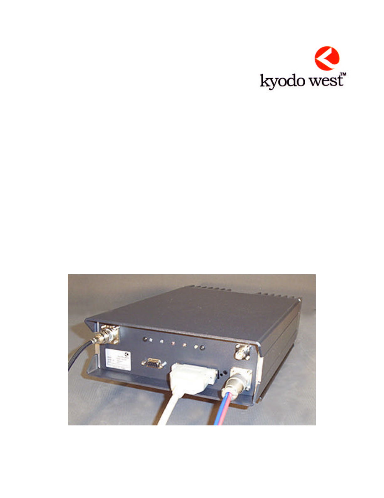
2.3 Product Description
The Kyodo West KG506 transceivers represent a great advance on the pr evious rugged & time proven
KG106 transceiver. They consist of separate modules all housed within one rugged, compact mobile
cabinet. The receiver, the transmitter, and the PA Unit are each enclosed within their own diecast
housings that are directly mounted to the main chassis. A full-featured logic module controls all
parameters of the radio under the control of a microprocessor. The RF Power Output is 1 - 30 Watts on a
continuous duty basis. The CTCSS module supports all EIA tones, which may be set on a per channel
basis during radio programming.
The KG506 is supplied with TX and RX antenna ports to allow connection to an external duplexer or
feeder cables. Space is provided inside the housing for an antenna relay or mobile type 6-cavity duplexer.
MODE L KG506 FULL-DUPLEX MOBILE
2
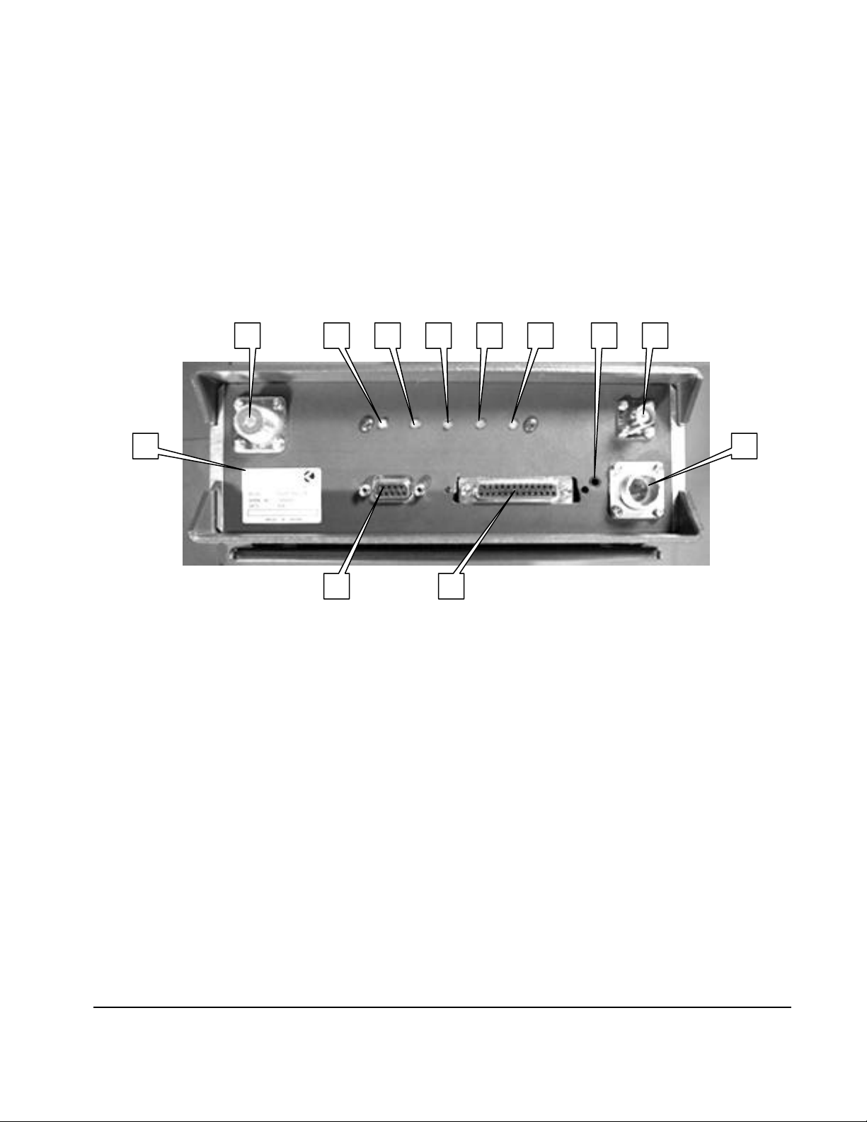
2.4 Front Panel Features
B C E D
The front panel includes the following:
1. UHF Type connector for the Transmitter (optional type “N”)
2. LEDs to indicate: A=POWER, B=BUSY, C=TRANSMIT, D=ALARM, and E=REPEAT
3. Miniature jack for speaker audio output
4. BNC Connector for the Receiver
5. DC Power Connector
6. 25 position D sub connector for interface to the external control system
7. 9 position D sub connector for connection to a PC for programming
8. Model Number / FCC Label
1 4 3
A
5 8
7 6
2.5 Indicator Functions
A POWER On Indicator LED
The Power ON Indicator LED will illuminate in Green (Blue on FCC sample) color whenever the
Power ON/OFF switch is switched to the "ON" position.
B BUSY Mode Indicator LED
The Busy Mode Indicator LED will illuminate in Green color whenever the KG506 receives a carrier
signal on the selected channel that is greater then the Squelch setting.
C TRANSMIT Mode Indicator LED
The Transmit Mode Indicator LED will illuminate in Red color whenever the KG506 is transmitting.
D ALARM Mode Indicator LED
The Alarm Mode Indicator LED will illuminate (Flashing) in Amber color whenever the transceiver
detects a fault in the receiver module, the transmitter module, or the PA module on the selected
channel.
E REPEATER Mode Indicator LED
The Repeater Mode Indicator LED will illuminate in Yellow color when the selected channel has
been programmed for Repeater operation. This LED will NOT illuminate on any channel that is
programmed to operate in Base Station mode.
MODE L KG506 FULL-DUPLEX MOBILE
3

3.0 OPERATION
3.1 Installation and Programming
KG506 can be installed to operate as a Transportable, Mobile or a Fixed Station in any mode of
operation.
The KG506 must be programmed before it will operate correctly. This is best done by the
equipment supplier or a competent radio engineer. They will require the correct programming kit
and a computer. Complete programming instructions are provided with the kit. If a duplexer is
used, please observe the maximum frequency range permitted by the duplexer notches.
It is important that the KG506 be correctly installed at its working location. It is recommended that
this be done by a competent radio engineer.
As a minimum, it is necessary to:
The antenna(s) used for this transmitter must be fixed-mounted on outdoor permanent
structures. RF exposure compliance is addressed at the time of licensing, as required by
the responsible FCC Bureau(s), including antenna co-location requirements of 1.1307(b)(3).
• Securely attach the mounting plate to the desired location.
• Connect the DC Input power lead to a suitable 13.8 Volt Regulated DC Power supply that
has sufficient capacity. (Ensure that the DC Polarity is correct, otherwise the fuse will
blow).
• Connect the antenna feed line(s). (Check that the VSWR of the antenna is acceptable).
• Connect the Control System to the 25 position sub D connector.
3.2 Basic Operation
Note that controls and functions will vary with different control systems and with programming.
3.2.1 Switch On
Switch the KG506 "ON" , the POWER indicator should illuminate.
3.2.2 Adjust the Volume Setting
Rotate the Volume Knob clockwise until the audio level from the speaker is suitable.
3.2.3 Adjust the Squelch Setting
Rotate the Squelch Knob clockwise (from the fully counter clockwise position) slowly until
the background noise can no longer be heard. It is wise to slightly rotate the knob further
in the clockwise direction so that variations in the background noise level do not "break"
the squelch setting and cause annoying noises to be heard from the speaker.
3.2.4 Select the Channel
Select the desired channel.
3.2.5 Receiving
You should now be able to hear any radio traffic that occurs on channel. It may be
necessary to further slightly adjust the Volume setting to suit your listening requirements.
3.2.6 Transmitting
Depending on the legal requirements in your country and the operating requirements
within your organization, it may be necessary to announce your Call Sign, and will
MODE L KG506 FULL-DUPLEX MOBILE
4
 Loading...