

Kyocera Mita FS-C8008N, FS-C8008DN Installation Manual
FS-C8008N/DN
Installation Guide
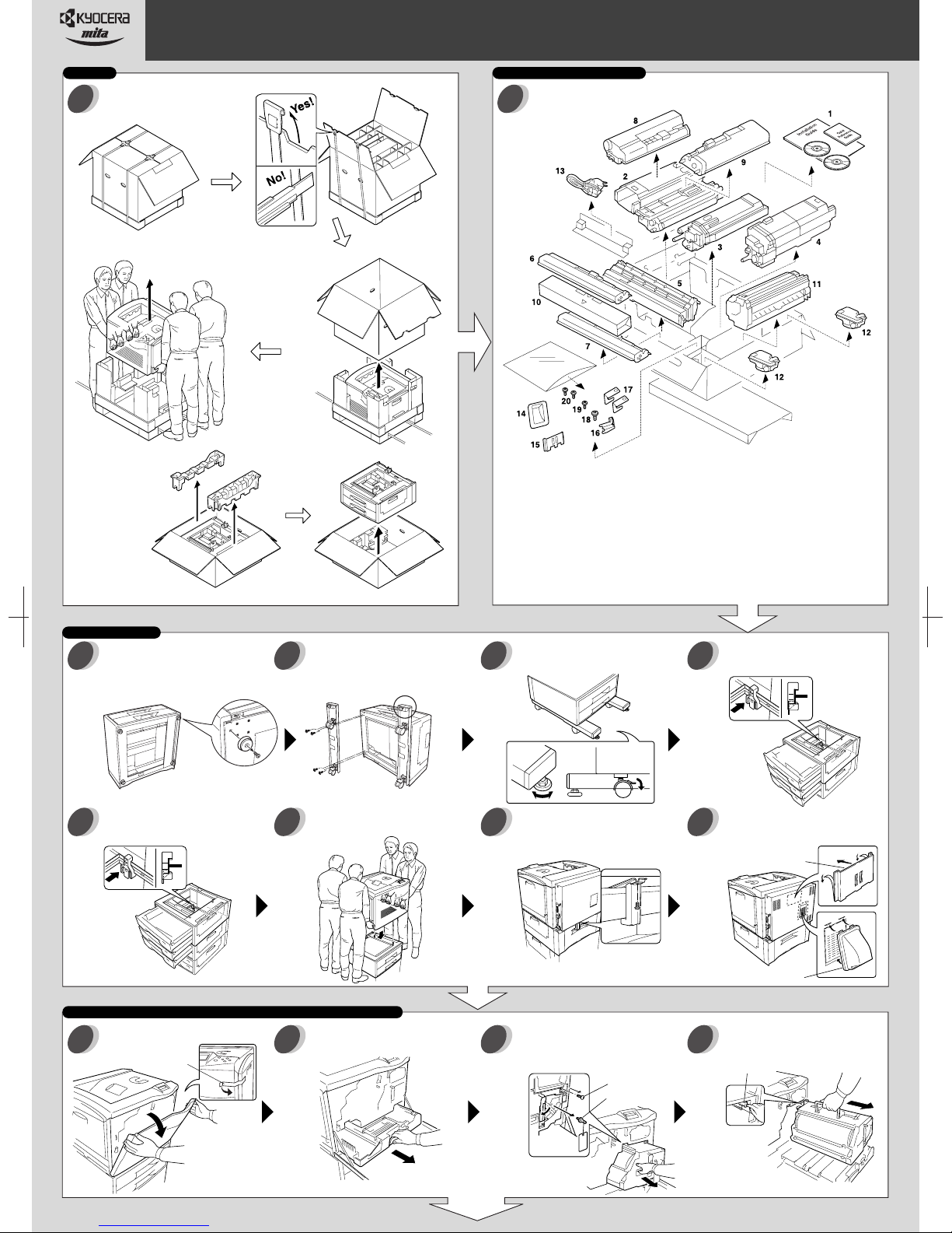
Unpacking the Printer
1 2
To avoid injury,
the printer must
be lifted and
carried by four
persons or more.
Important!
Installation should be performed only by a qualified service personnel. Kyocera Mita
assumes no liability for any damage caused by an improper installation of the printer.
Checking Parts and ComponentsUnpacking
1 Documents
Unpacking
the Paper Feeder
PF-30A for FS-C8008N
PD-800 for FS-C8008DN
The following setup assumes three paper feeders to be installed with the printer (including the one supplied as a standard accessory), which requires a CA-31B caster kit to
be installed on the bottom of the bottom paper feeder. If the extra paper feeders are not installed, the CA-31 casters may be used. See the Operation Guide for more details.
Placing the Printer
Attaching the Caster kit (purchased
separately): Stand the paper feeder on its
3
back side. Remove each one screw to
remove four feet.
Using another topple-resistant bracket,
stack and joint the middle and top paper
7 8 9
feeder.
Install the caster kit onto the bottom of the
paper feeder.
4 5 6
Be sure to face
the longer end
towards the front
of the feeder.
Place the printer over the paper feeders (by
at least four persons).
Installation Guide (This sheet)
Quick Reference Guide
CD-ROMs
2 Cyan Developer
3 Magenta Developer
4 Yellow Developer
5 Black Developer
6 Cyan Toner Container
7 Magenta Toner Container
8 Yellow Toner Container
9 Black Toner Container
Place the paper feeder in a proper location.
Lock the stopper for each caster. Turn the
bolts to adjust height.
Join the printer and topmost paper feeder
with the jig provided by using one screw.
10
10 Secondary Transfer Unit
11 Fuser Unit
12 Waste Toner Boxes
13 Power Cord
14 Exhaust Duct
15 Quick Reference Guide Holder
16 Jig (Used in step 9)
17 Secondary Transfer Unit Anchor Jig
(Used in step 20)
18 Screw M4 (Used in step 9)
19 Screw M3 (Used in step 16)
20 Screws M3 (Used in step 20)
Using a topple-resistant bracket (supplied
with the CA-31B caster kit), stack and joint
the bottom and middle paper feeder.
Install the exhaust duct and the quick
reference guide holder. Peel the protective
tape off when attaching the holder.
Quick Reference
Guide Holder
Installing the Fuser Unit, Secondary Transfer Unit, and Waste Toner Box
Remove the tape and then open the
11 12 13 14
front cover.
Tape
Pull out thoroughly the paper transfer unit.
Continued on
the Reverse Page
Unscrew the screw. Remove the lock pin
and release the (green-colored) lock lever.
Pull out the primary transfer unit until it
stops.
Screw
Lock Pin
Exhaust Duct
While pushing the gray lever, pull out
the primary transfer unit. Make sure
not to scratch the roller.
Gray Lever

2002, 2003 by KYOCERA MITA CORPORATION All rights reserved. 2-28, 1-Chome, Tamatsukuri, Chuo-ku, Osaka 540-8585, Japan
Installing the Fuser Unit, Secondary Transfer Unit, and Waste Toner Box
Open the paper guide. Insert the fuser unit
onto the paper transfer unit.
15 16 17 18
Fuser Unit
Fix the fuser unit with one screw.
Open the fuser top cover.
Firmly tighten two screws. Close the fuser
top cover, then close the paper guide.
Paper Guide
Install the secondary transfer unit.
19 20 21 22
Secondary
Transfer Unit
Inserting the Developer Units
Unscrew the four screws. Free the two
stoppers.
23 24 25 26
Anchor the secondary transfer unit to the
printer using the included anchor jig and
screw.
Secondary Transfer
Unit Anchor Jig
Pull out the process frame.
Process Frame
Fuser
Top Cover
Install the waste toner box.
Waste Toner Box
Remove the 2 tags and then both the
front and rear stoppers.
Tag
Tag
Rear stopper
Front
stopper
Close the paper transfer unit.
Peel off the tapes from the developer units
and remove the protective pad from each
unit.
Black
Cyan
Magenta
Yellow
Set the black developer facing the
developing roller towards you.
27 28 29 30
Developing
Roller
Close the process frame and then close
the stoppers. Fix the two (A) screws first,
31 32 33 34
and then fix the two (B) screws.
Installing the Toner Containers
Shake each toner container well
before use. Install the four toner
35 36
containers into their corresponding
developer units.
Set the cyan developer. Set the magenta developer. Set the yellow developer.
Pull out the paper transfer unit.
Close the front cover.
Reinstall the primary transfer unit. Insert
it thoroughly on the rails.
Making Connections
Connect to the computer.
37 38
USB Interface
Close the lock lever. Fix the screw.
Reinsert the paper transfer unit.
Connect the power cord to the
power outlet. Turn on the printer
power switch.
Black
Yellow
Magenta
Cyan
Network Interface
(Ethernet)
Parallel Interface
For more information about the printer, refer to the Operation Guide (PDF) in the CD-ROM supplied with the printer.
Printed in Japan 2003.1EC 2CK80011B
 Loading...