

Kyocera Mita FS-3700 User Manual
Chapter 1
Installing the Printer
This chapter explains how to unpack and install the printer. The topics covered are:
Positioning the printer
Unpacking and inspection
Names of parts
Setting up and interfacing
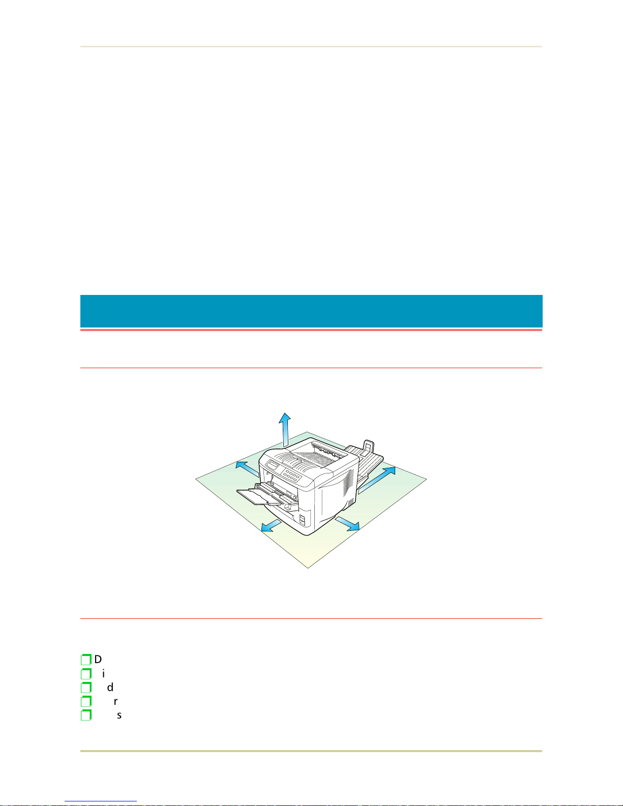
1.1. Positioning the Printer
Clearance
Allow at least the necessary minimum clearance around the printer (see below). A total space
of 92 cm by 61 cm by 138 cm (36 by 24 by 54 inches) is needed.
Places to Avoid
Avoid installing the printer in locations subject to:
p
Direct drafts of hot or cold air
p
Direct drafts from outside (Avoid locations near doors leading outside.)
p
Sudden temperature or humidity changes
p
Sources of high temperature, for example, near stoves or radiators
p
Excessive dust
30 cm (12 inches)
40 cm (16 inches)
[20 cm (8 inches) when
the face-up output tray is
not installed.]
25 cm (10 inches)
60 cm (24 inches)
30 cm (12 inches)
1.1. Positioning the Printer
1-1
p
Vibration
p
Ammonia or other harmful fumes. (If you are planning to fumigate the room, or make
liberal use of insecticide, remove the printer first!)
p
Excessive sunlight or humidity
p
Lack of ventilation
p
Low air pressure, e.g., located more than 2000 meters (6500 feet) above sea level
Basic requirements
The printer will work best if it is installed in a location that is:
p
Near the computer
If the parallel interface is used to connect the printer to the computer, the connecting cable
should be shielded type and not be longer than 3 meters (10 feet).
p
Level and well supported
Place the printer on a sturdy table or desk. Do not place the printer on an unstable cart, stand,
or table. The printer may fall, causing injury, or serious damage to the printer.
p
Near an AC wall outlet, preferably one that can be used for the printer alone (see section Power Supply on next page).
Power requirements are:
Voltage
120 V (U.S.A./Canada), 220 V to 240 V (European countries), 10 % at each voltage
Frequency
60 Hz (120 V), 2 %
50 Hz (220 V to 240 V), 2 %
Current
capacity
FS-1700: Max. 5.8 A at 120 V, or Max 3 A at 220 V to 240 V
FS-3700: Max. 7.8 A at 120 V, or Max 4 A at 220 V to 240 V
The outlet should be earthed, or an adapter should be used.
If an extension cord is used, the total length of the power cord plus extension should be 5 meters (17 feet) or less.
p
Well ventilated, not too hot or cold, and not too damp or dry
Temperature
10°C to 32.5°C, ideally about 20°C (50°F to 90.5°F, ideally about 68°F)
Humidity
20% to 80%, ideally 65%
If you install the printer where the temperature or humidity is outside the above ranges, you
may not get the best print quality, and there will be an increased chance of paper jams.
±
±
±
1.1. Positioning the Printer
1-2
Power Supply
The printer should not be on the same power circuit as an air conditioner, fluorescent light,
copier, or shredder, because these devices generate electrical noise on the power line. If it
must share a power circuit with equipment like this, a high-frequency noise filter or isolation
transformer is advisable. (Filters and transformers are available commercially.)
Avoid using plug multipliers to connect a large number of devices on the same circuit as the
printer.
If the power from the outlet itself appears to be unstable, a line stabilizer should be used. In
places where the voltage tends to fluctuate, it may be necessary to install a voltage regulator.
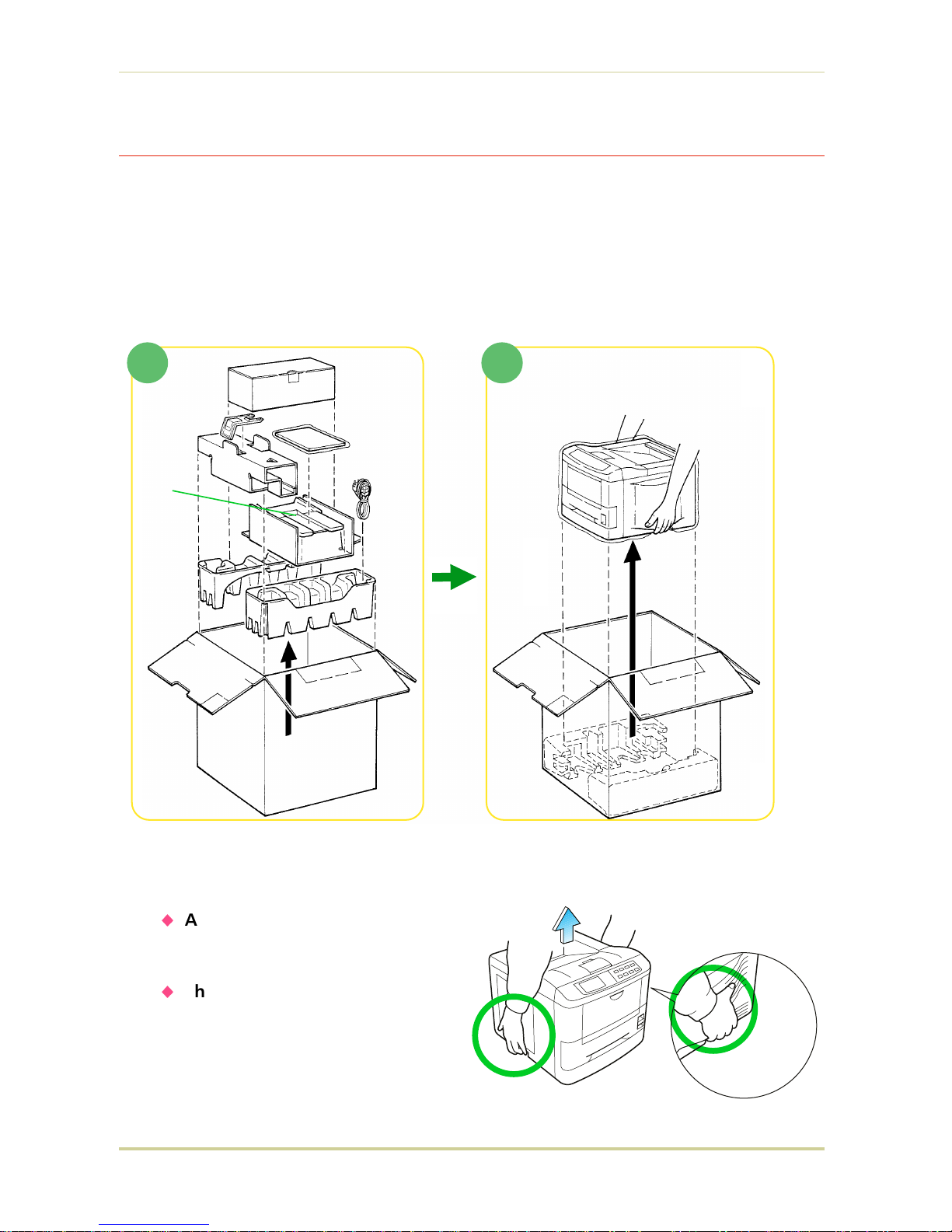
1.2. Unpacking and Inspection
The printer is packed as shown below. Unpack the printer following diagrams 1 and 2 on the
next page. While unpacking it, check that the listed parts are all accounted for.
Examine the package for any signs of damage that may have been caused during transportation. If the carton is found to be badly damaged, leave the carton unopened and immediately
notify the dealer from whom you purchased the printer.
Save the box and other packing materials in case you have to repack the printer for transportation at a later date.
As the disconnect device is not incorporated in the printer’s AC primary circuit, an
easily accessible socket outlet must be provided near the equipment.
If the printer is used with the optional Sorter (SO-6) or Stacker (ST-20), in order to
avoid short-circuiting, it should be ensured that these devices are plugged securely
into their respective power outlets.
Da kein Trennschalter in den Wechselstrom-Primärkreis des Druckers eingebaut ist,
muß eine leicht zugängliche Steckdose in der Nähe des Gerätes vorhanden sein.
Wenn der Drucker mit dem gesonderten Sorter (SO-6) oder Stapler (ST-20) verwendet wird, muß darauf geachtet werden, daß diese Geräte einwandfrei an separate
Steckdosen angeschlossen sind, um Kurzschluß zu vermeiden.
1.2. Unpacking and Inspection
1-3
List of shipped components
❐ (A ) Toner kit, including a toner container, waste toner bottle, and a wiper cloth
❐ (B ) Paper stopper
❐ (C ) Container for the developer unit (including a plastic bag)
❐ (D )Manuals : User’s Manual (Kyocera Digital Library CD-ROM, including the printer
drivers), Installation Manual (this booklet)
❐ (E ) Face-up output tray
❐ (F ) Power cord
To remove the printer from the box, grasp the handholds on either side of the printer. Lift the
printer from the carton as shown below.
☛
u
Always use these handholds
whenever you lift or move
the printer.
u
The handhold on the right
side of the printer doubles as
the memory card slot. Be sure
to remove the memory card
first, if inserted, before lifting
or moving the printer.
(B)
(C)
(D)
(E)
(A)
1 2
Printer
(F)
1.2. Unpacking and Inspection
1-4
1.3. Names of Parts
This section takes you on a guided tour of the printer, pointing out its major parts. The part names
introduced here will be used throughout this manual.
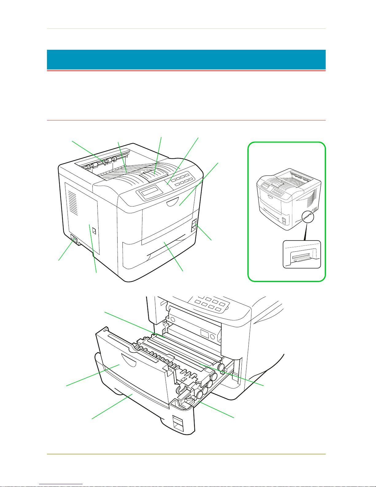
Front View
Memory Card Slot
Transfer Roller
Registration Roller
Paper Feed Unit
Multi-Purpose
Tray
Paper Cassette
Control Panel
Multi-Purpose
Tray
Paper Feed Unit
Release Lever
Paper Cassette
Side Cover
Power Switch
Face-down
Output Tray
Paper Stopper
Paper Full Sensor
(Model FS-3700 only)
1.3. Names of Parts
1-5
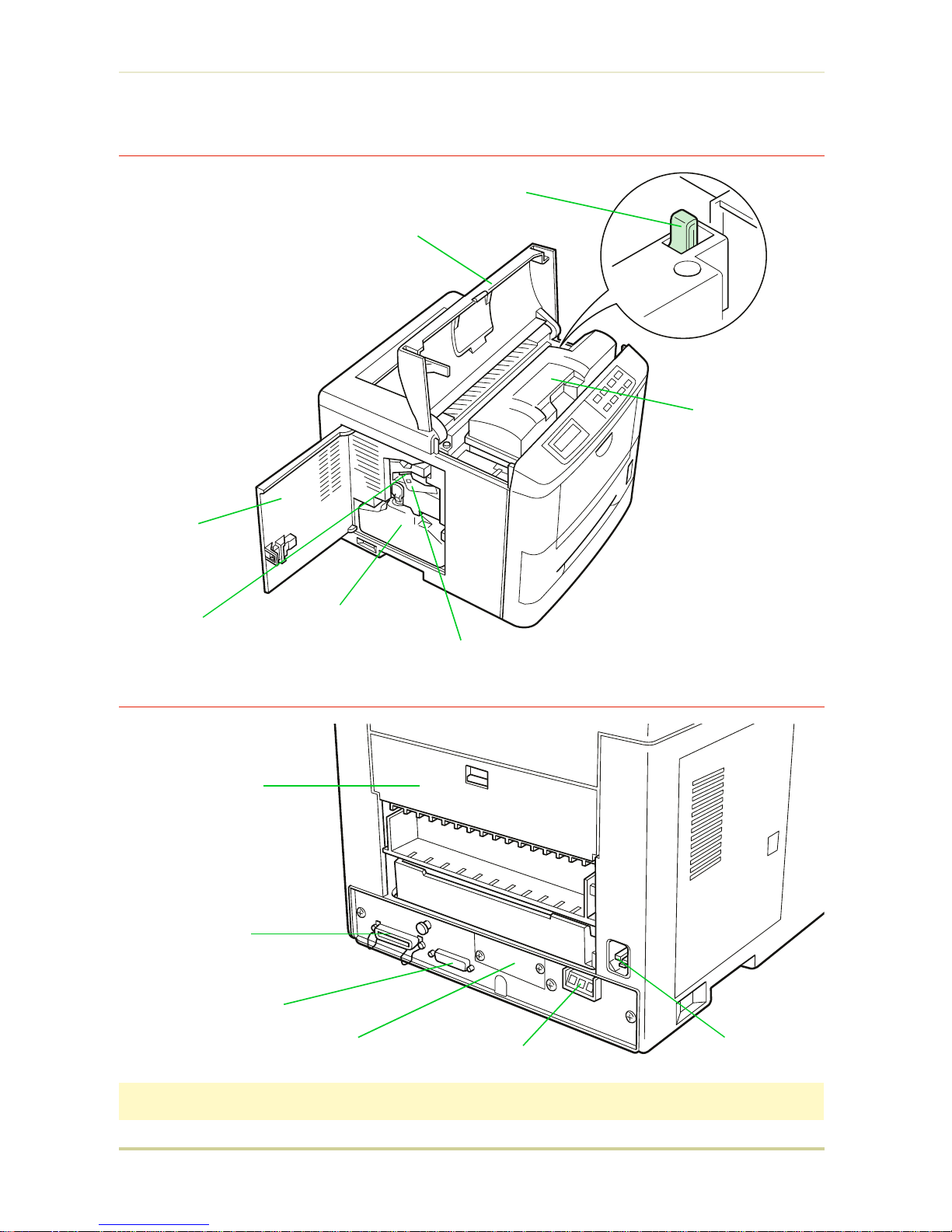
Interior View
Rear View
Rear Cover
Power Cord
Receptacle
Option Paper
Handler/Stacker Connector*
Serial Interface
(RS-232C/RS-422A) Connector*
Parallel Interface
Connector*
Option Interface Slot Cover
*: To protect the printer against static discharge, the connector must be covered with the supplied
protective cap when not in use.
Toner Container Release
Lever (Green)
Toner Container
Top Cover
Side Cover
Waste Toner Bottle
Cleaner Knob (Green)
Main Charger Unit
1.3. Names of Parts
1-6

1.4. Setting Up and Interfacing
Before you can use the printer for the first time, you must set up the printer by installing the
printer components and interfacing with the computer. The steps to be followed in setting up
are:
1.
Open the top cover.
2.
Install the toner container.
3.
Close the top cover.
4.
Install the waste toner bottle.
5.
Add paper.
6.
Open the paper stopper on the face-down output tray.
7.
Install the face-up output tray (if required).
8.
Connect the printer to the computer.
9.
Attach the power cord.
10.
Print a status page.
11.
Test the interface with the computer.
12.
Set the emulation mode.
13.
Install the printer driver.
1.4. Setting Up and Interfacing
1-7
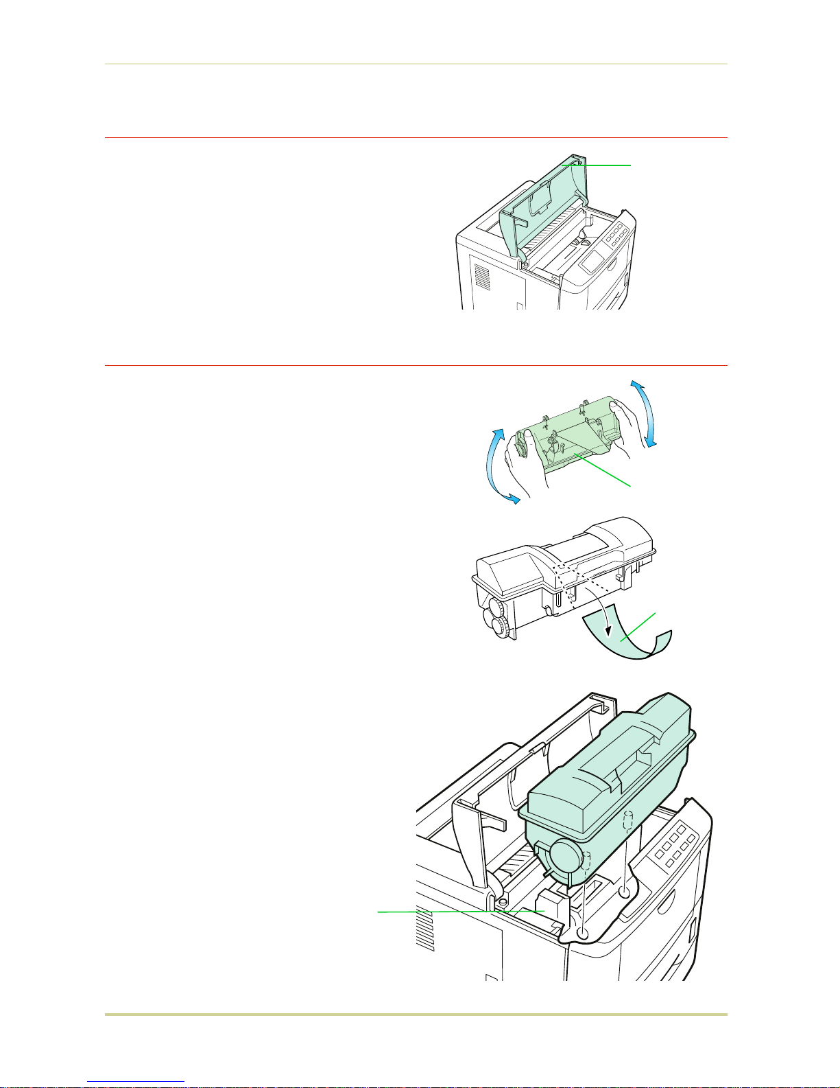
1—Open the Top Cover
1. Remove the packing tape from the printer.
2. Open the printer top cover all the way.
2—Install the Toner Container
1. Take the toner container from the toner kit.
2. With the label side down, thoroughly shake
the toner container (in the direction of the arrow) ten times or more to loosen and mix the
toner inside.
3. The bottom of the toner container is sealed
with a sealing strip. Peel off the seal on the
toner container and carefully pull off and dispose of the sealing strip.
☛ Be sure to peel the seal off the toner
container before the toner container
is fitted into the developer unit.
4. Install the toner container on the developer
as show in the diagram.
Top Cover
Toner Container
Developer Unit
Sealing strip
1.4. Setting Up and Interfacing
1-8
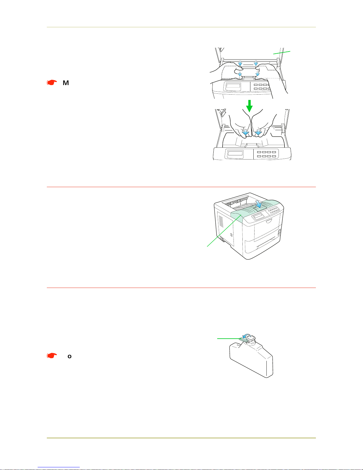
5.
When the toner container is installed correctly on the developer, push the top of the
container unit ("PUSH HERE") until it locks in.
*
Make sure that the toner container
is properly locked in the printer.
3—Close the Top Cover
Close the top cover by pressing the arrowed
part in this diagram.
4—Install the Waste Toner Bottle
The waste toner bottle is in the toner kit supplied with the printer. The waste toner bottle
must be installed in the printer.
Install the waste toner bottle in the printer as follows.
1.
Take the waste toner bottle from the toner
kit supplied.
*
Do not cap the waste toner bottle.
Top Cover
Top Cover
Waste Toner
Bottle
Cap
1.4. Setting Up and Interfacing
1-9
 Loading...