

Kyocera Mita FS-1900 Installation Manual
Installation Guide
Caution
NO LIABILITY IS ASSUMED FOR ANY DAMAGE CAUSED BY IMPROPER INSTALLATION.
Notice on Software
SOFTWARE USED WITH THIS PRINTER MUST SUPPORT THE PRINTER’S EMULATION MODE. The
printer is factory-set to emulate the HP PCL 6. The emulation mode can be changed by following the procedures
described in the Operation Guide contained as an electronic file in the Kyocera Mita Digital Library CD-ROM
supplied with the printer.
Notice
The information in this manual is subject to change without notification. Additional pages may be inserted in
future editions. The user is asked to excuse any technical inaccuracies or typographical errors in the present
edition.
No responsibility is assumed if accidents occur while the user is following the instructions in this manual. No
responsibility is assumed for defects in the printer’s firmware (contents of its read-only memory).
This manual, any copyrightable subject matter sold or provided with or in connection with the sale of the page
printer, are protected by copyright. All rights are reserved. Copying or other reproduction of all or part of this
manual, any copyrightable subject matter without the prior written consent of Kyocera Corporation is prohibited. Any copies made of all or part of this manual, any copyrightable subject must contain the same copyright
notice as the material from which the copying is done.
Table of Contents
STEP 1 Unpacking.........................................................................1
STEP 2 Positioning the Printer .....................................................2
STEP 3 Installing the Toner Container .........................................3
STEP 4 Installing the Waste Toner Box ........................................5
STEP 5 Connecting the Printer to the Computer.........................7
STEP 6 Connecting the Power Cord ............................................9
STEP 7 Adding Paper to the Paper Cassette and MP Tray .......10
STEP 8 Turning the Power Switch On ........................................17
STEP 9 Printing a Status Page....................................................18
©2001 by KYOCERA CORPORATION All rights reserved
Revision 1.0 October 2001
STEP
1
Unpacking
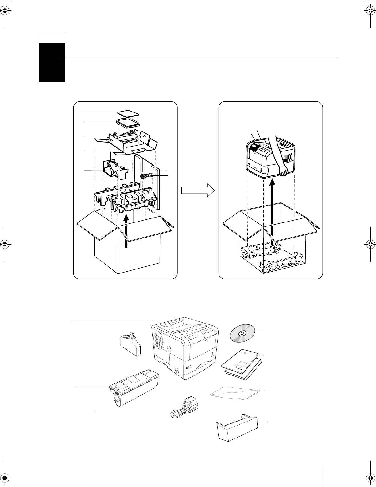
Carefully remove the printer and other items from the box. Check that nothing is missing against the list of shipped components below.
List of Shipped Components
(A)
(B)
(C)
(D)
(for
U.S.A.
only)
(E)
Printer
Waste Toner
Box (E)
Printer
(F)
Kyocera Mita Digital
Library CD-ROM (B)
Installation Guide
[this booklet] and
other printed matter
(B)
To n er
Container (D)
Power Cord (F)
Plastic Bag for
Developer Unit (A)
Dust Cover (C)
[for U.S.A. only]
1
STEP
2
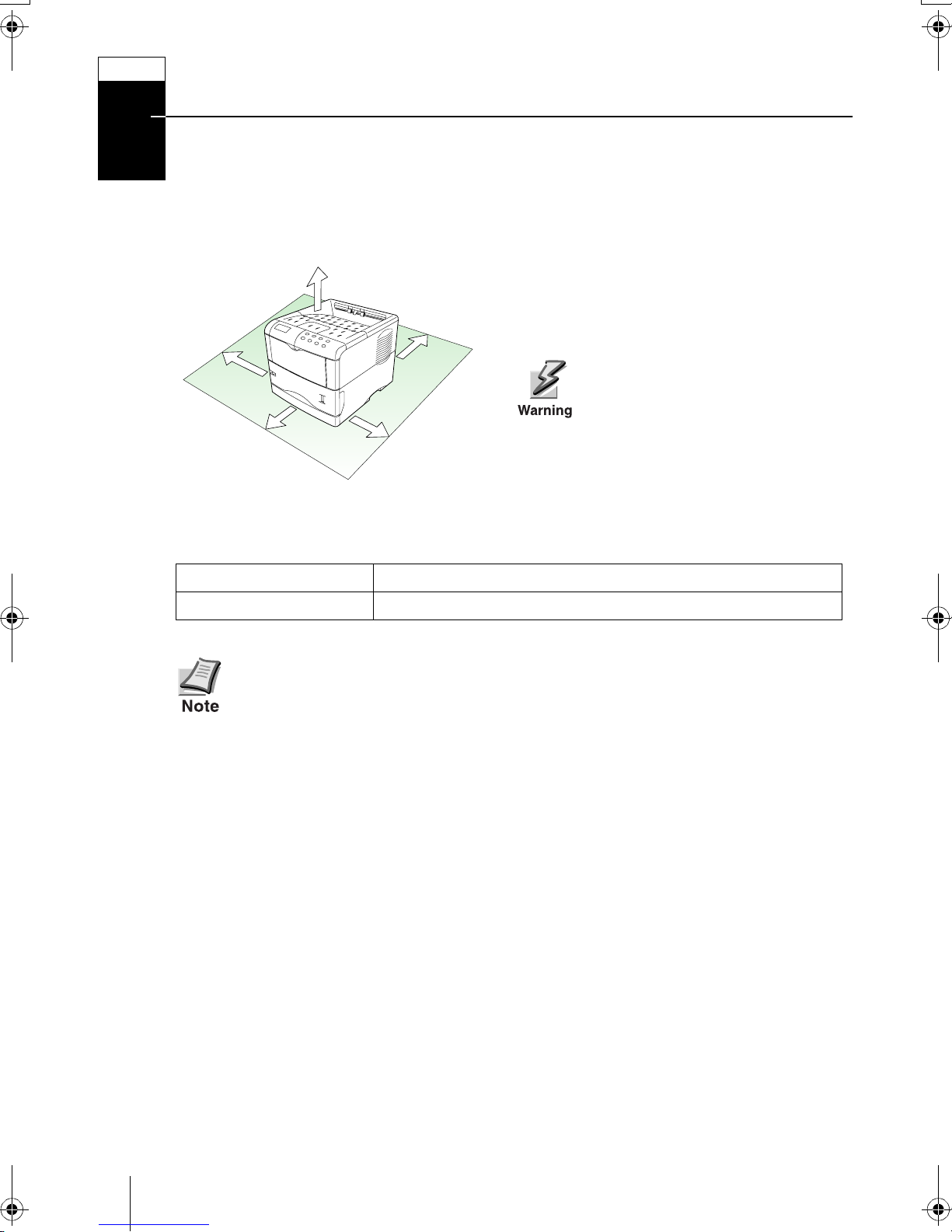
Positioning the Printer
Make sure that the place of installation meets the following requirements:
Clearance
30 cm (11-13/16 inches)
20 cm (7-7/8 inches)
[40 cm (15-3/4 inches) when the option
30 cm
(11-13/16
inches)
60 cm
(23-5/8
inches)
face-up output tray is installed]
25 cm
(9-7/8
inches)
Be sure to secure enough space
around the printer. Prolonged
use without sufficient clearance
may cause heat to build up
within the printer, resulting in
fire.
Environment
Te m pe r at u re
Humidity
Do not install the printer where temperature or humidity is outside the recommended range. Print quality may suffer and there will be an increased
chance of paper jams.
10 to 32.5 °C (50 to 90.5 °F), ideally about 23 °C (73.4 °F)
20 to 80 %, ideally 60 %
Places to Avoid
Avoid installing the printer in locations subject to:
• Direct drafts of hot or cold air
• Direct drafts from outside (Avoid locations near building entrances.)
• Sudden temperature or humidity changes
• Sources of high temperature, for example, near stoves or radiators
•Excessive dust
•Vibration
• Unstable surfaces and surfaces that are not level
• Ammonia or other harmful fumes (If you are planning to fumigate the room, or
make liberal use of insecticide, remove the printer first!)
• Excessive sunlight or humidity
• Lack of ventilation
• Low air pressure, e.g., elevations greater than 2000 meters (6500 feet) above
sea level
2
STEP
3
Installing the Toner Container
Before you can use the printer for the first time, you must prepare it by installing the
toner container, waste toner box, and set up the interfacing with the computer.
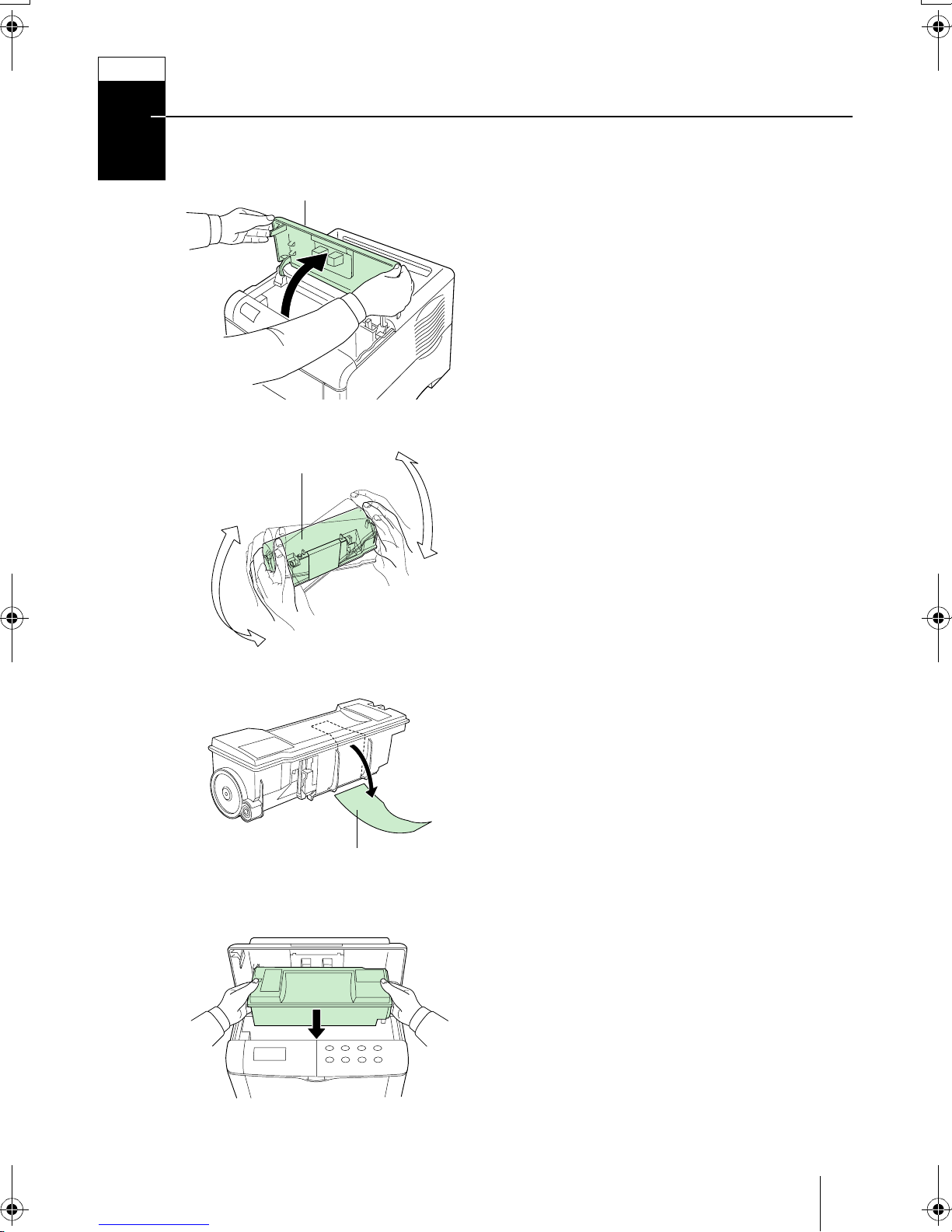
10 times or
more
To p Co ver
Toner Container
1 Open the printer top cover all the way.
2 Take the toner container from the bag.
3 With the label side down, thoroughly
shake the toner container (in the direction of the arrow) ten times or more to
loosen and mix the toner inside.
Protective Seal
4 Carefully remove the protective seal.
5 Install the toner container into the
printer.
3
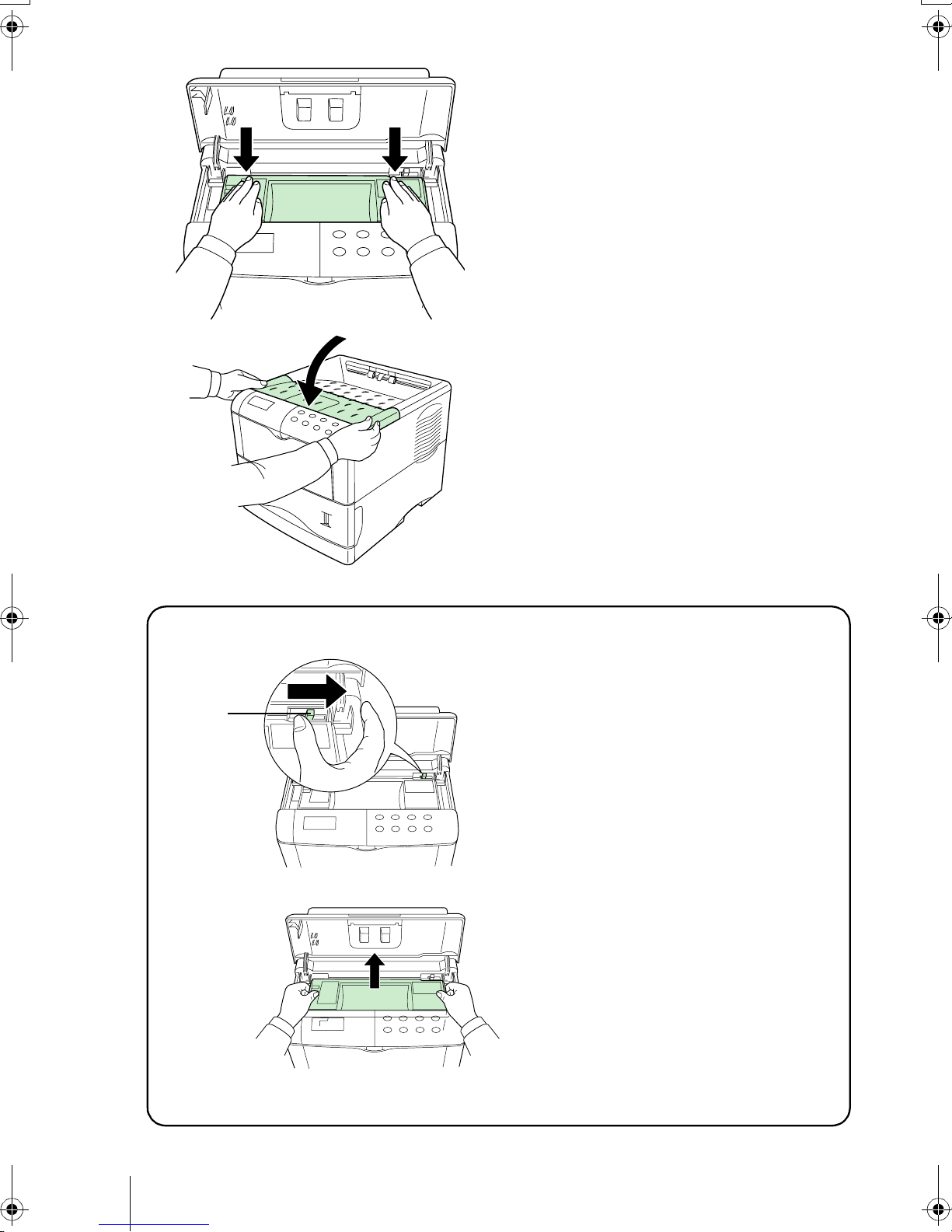
6 Push firmly on the top of the toner con-
tainer at the positions marked PUSH
HERE.
When the toner container fits into place,
it will lock with a clicking sound.
7 Close the top cover.
To remove the toner container
Lock Lever
Pull the lock lever (green colored) to
the right and gently lift the toner container.
4
STEP
4
Installing the Waste Toner Box
The waste toner box is supplied with the printer. The waste toner box must be installed
in the printer.
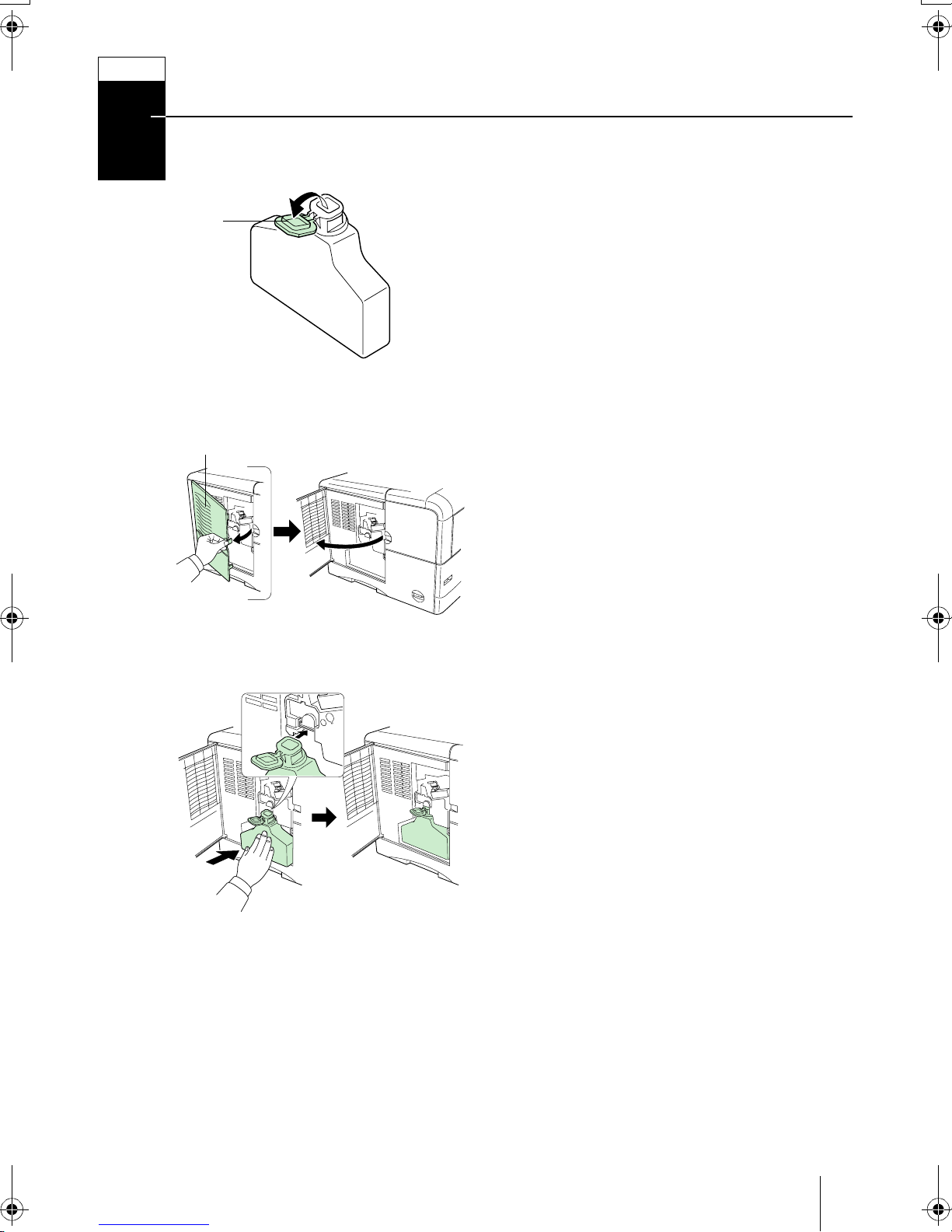
1 Open the cap of the waste toner box.
Cap
Waste Toner
Box
Left Cover
2 Open the left cover on the left side of the
printer.
3 Insert the waste toner box as shown in
the figure. The box will be locked when
it fits into place.
5
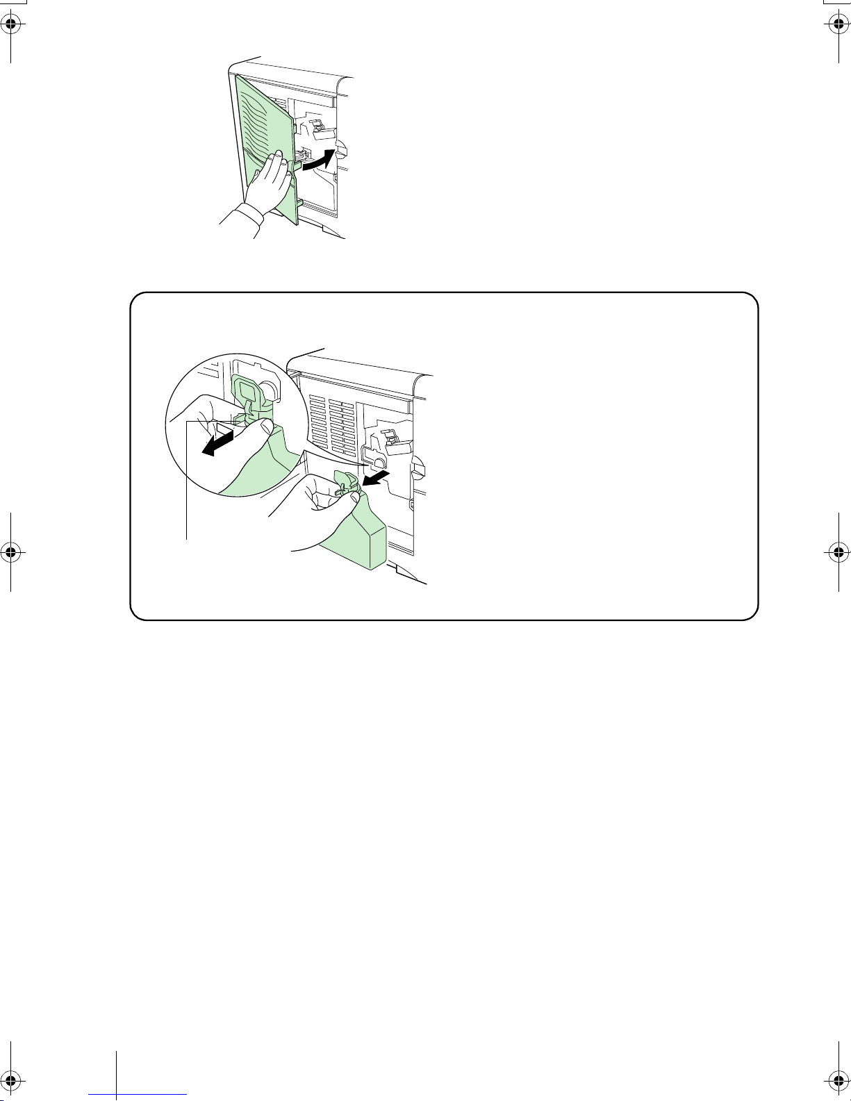
To remove the Waste Toner Box
4 Ensuring that it is correctly inserted,
close the left cover.
While holding the waste toner box,
press the lock lever and then gently
remove the waste toner box.
Lock Lever
6
STEP
5
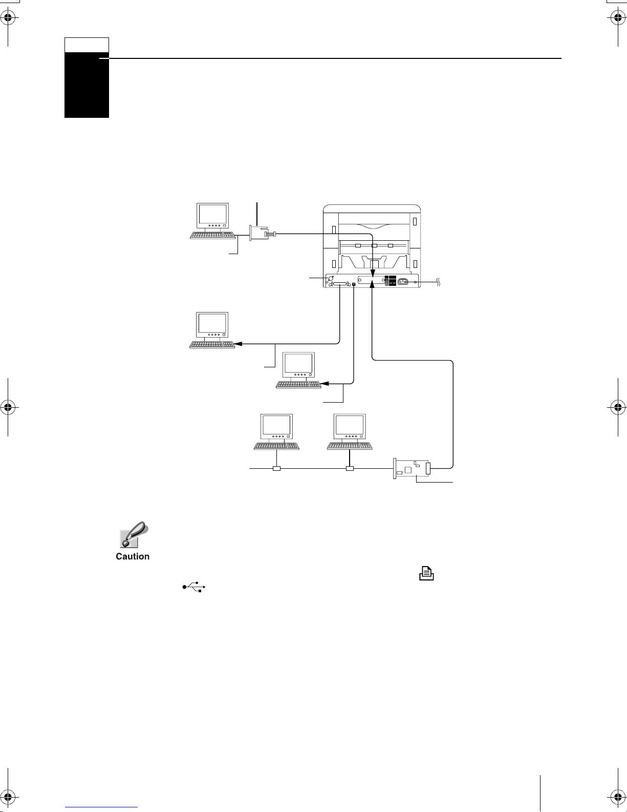
Connecting the Printer to the Computer
There are various ways of connecting the printer to the computer, such as through the
parallel interface connector, through the USB (Universal Serial Bus) interface connector, through the option serial interface board kit (IB-10E) or through the option network
interface card.
Printer Connections
Option Serial Interface
Board Kit (3.3 V DC)
Printer (Rear)
Serial Interface
Connector for option sorter
(See the option sorter’s
user’s manual.)
Power Supply
Parallel Interface
USB Interface
Network
Before performing this step, be sure to turn off both the printer and the computer’s power switches and unplug the printer’s power plug from the power
outlet. Failure to do so may result in electrical shock.
The standard Centronics parallel interface connector ( ) and USB interface
connector ( ) are located on the rear of the printer.
Option Network
Interface Card
(3.3 V DC)
7
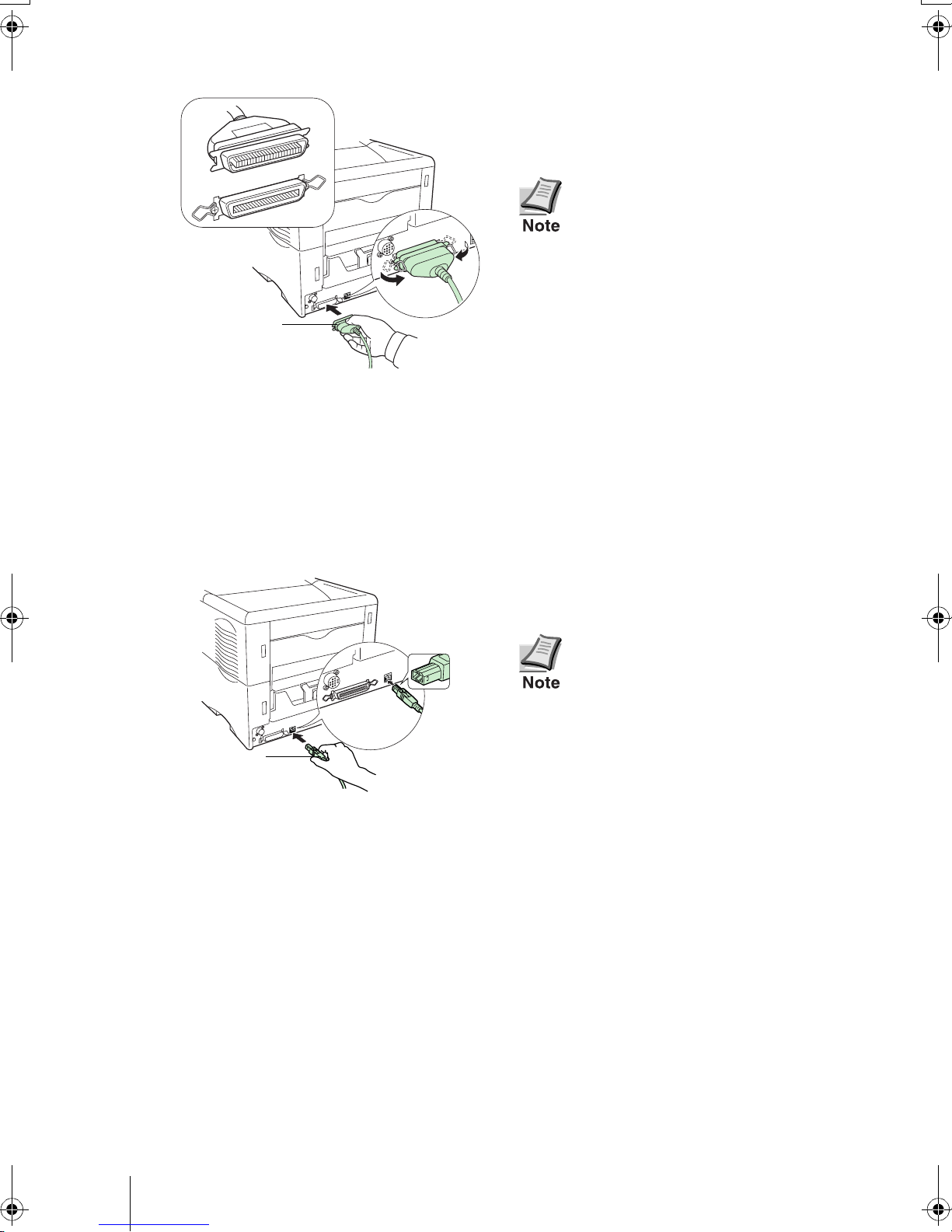
Parallel Interface Connection
1 Plug one end of the printer cable (not
included) into the parallel interface connector on the rear of the printer.
Clip
Parallel Printer
Cable
Clip
• Use a parallel printer cable
that complies with the
IEEE1284 standards.
• The printer will work best if it
is installed near the c omputer.
The connecting cable should
be shielded and not be longer
than 3 meters (10 feet).
2 Close the clips on both sides to fix the
connector in place.
Plug the other end of the printer cable
into the computer’s parallel interface
connector.
USB (Universal Serial Bus) Interface Connection
1 Plug one end of the USB cable on the
rear of the printer.
USB Cable
•Use a cable that complies
with Revision 1.1 of USB standard.(a rectangular Type A
plug and a square Type B
plug).
• The connecting cable should
be shielded and not be longer
than 5 meters (16 feet).
2 Plug the other end of the USB cable into
the computer’s USB interface connector.
8
 Loading...