

Kyocera Mita DF-75 Service Manual

DF-75
SERVICE
MANUAL
Published in Aug.’01
5FG70760

CAUTION
DANGER OF EXPLOSION IF BATTERY IS INCORRECTLY REPLACED. REPLACE ONLY WITH
THE SAME OR EQUIVALENT TYPE RECOMMENDED BY THE MANUFACTURER. DISPOSE OF
USED BATTERIES ACCORDING TO THE MANUFACTURER’S INSTRUCTIONS.
ATTENTION
IL Y A DANGER D’EXPLOSION S’IL Y A REMPLACEMENT INCORRECT DE LA BATTERIE.
REMPLACER UNIQUEMENT AVEC UNE BATTERIE DU MÊME TYPE OU D’UN TYPE RECOMMANDÉ PAR LE CONSTRUCTEUR. METTRE AU RÉBUT LES BATTERIES USAGÉES
CONFORMÉMENT AUX INSTRUCTIONS DU FABRICANT.

Safety precautions
This booklet provides safety warnings and precautions for our service personnel to ensure the safety of
their customers, their machines as well as themselves during maintenance activities. Service personnel
are advised to read this booklet carefully to familiarize themselves with the warnings and precautions
described here before engaging in maintenance activities.
Safety warnings and precautions
Various symbols are used to protect our service personnel and customers from physical danger and
to prevent damage to their property. These symbols are described below:
DANGER: High risk of serious bodily injury or death may result from insufficient attention to or incorrect
compliance with warning messages using this symbol.
WARNING:Serious bodily injury or death may result from insufficient attention to or incorrect compliance
with warning messages using this symbol.
CAUTION: Bodily injury or damage to property may result from insufficient attention to or incorrect
compliance with warning messages using this symbol.
Symbols
The triangle ( ) symbol indicates a warning including danger and caution. The specific point
of attention is shown inside the symbol.
General warning.
Warning of risk of electric shock.
Warning of high temperature.
indicates a prohibited action. The specific prohibition is shown inside the symbol.
General prohibited action.
Disassembly prohibited.
indicates that action is required. The specific action required is shown inside the symbol.
General action required.
Remove the power plug from the wall outlet.
Always ground the copier.

1. Installation Precautions
WARNING
• Do not use a power supply with a voltage other than that specified. Avoid multiple connections to
one outlet: they may cause fire or electric shock. When using an extension cable, always check
that it is adequate for the rated current. ............................................................................................
• Connect the ground wire to a suitable grounding point. Not grounding the copier may cause fire or
electric shock. Connecting the earth wire to an object not approved for the purpose may cause
explosion or electric shock. Never connect the ground cable to any of the following: gas pipes,
lightning rods, ground cables for telephone lines and water pipes or faucets not approved by the
proper authorities. .............................................................................................................................
CAUTION:
• Do not place the copier on an infirm or angled surface: the copier may tip over, causing injury. .....
• Do not install the copier in a humid or dusty place. This may cause fire or electric shock. ..............
• Do not install the copier near a radiator, heater, other heat source or near flammable material.
This may cause fire. ..........................................................................................................................
• Allow sufficient space around the copier to allow the ventilation grills to keep the machine as cool
as possible. Insufficient ventilation may cause heat buildup and poor copying performance. ..........
• Always handle the machine by the correct locations when moving it. ..............................................
• Always use anti-toppling and locking devices on copiers so equipped. Failure to do this may
cause the copier to move unexpectedly or topple, leading to injury..................................................
• Avoid inhaling toner or developer excessively. Protect the eyes. If toner or developer is
accidentally ingested, drink a lot of water to dilute it in the stomach and obtain medical attention
immediately. If it gets into the eyes, rinse immediately with copious amounts of water and obtain
medical attention. ..............................................................................................................................
• Advice customers that they must always follow the safety warnings and precautions in the copier’s
instruction handbook. ........................................................................................................................
2. Precautions for Maintenance
WARNING
• Always remove the power plug from the wall outlet before starting machine disassembly...............
• Always follow the procedures for maintenance described in the service manual and other related
brochures. .........................................................................................................................................
• Under no circumstances attempt to bypass or disable safety features including safety
mechanisms and protective circuits. .................................................................................................
• Always use parts having the correct specifications...........................................................................
• Always use the thermostat or thermal fuse specified in the service manual or other related
brochure when replacing them. Using a piece of wire, for example, could lead to fire or other
serious accident. ...............................................................................................................................
• When the service manual or other serious brochure specifies a distance or gap for installation of a
part, always use the correct scale and measure carefully. ...............................................................
• Always check that the copier is correctly connected to an outlet with a ground connection. ............
• Check that the power cable covering is free of damage. Check that the power plug is dust-free. If
it is dirty, clean it to remove the risk of fire or electric shock. ............................................................
• Never attempt to disassemble the optical unit in machines using lasers. Leaking laser light may
damage eyesight. ..............................................................................................................................
• Handle the charger sections with care. They are charged to high potentials and may cause
electric shock if handled improperly. .................................................................................................
CAUTION
• Wear safe clothing. If wearing loose clothing or accessories such as ties, make sure they are
safely secured so they will not be caught in rotating sections...........................................................
• Use utmost caution when working on a powered machine. Keep away from chains and belts. .......
• Handle the fixing section with care to avoid burns as it can be extremely hot. .................................
• Check that the fixing unit thermistor, heat and press rollers are clean. Dirt on them can cause
abnormally high temperatures...........................................................................................................
• Do not remove the ozone filter, if any, from the copier except for routine replacement....................
• Do not pull on the AC power cord or connector wires on high-voltage components when removing
them; always hold the plug itself. ......................................................................................................
• Do not route the power cable where it may be stood on or trapped. If necessary, protect it with a
cable cover or other appropriate item. ..............................................................................................
• Treat the ends of the wire carefully when installing a new charger wire to avoid electric leaks........
• Remove toner completely from electronic components. ...................................................................
• Run wire harnesses carefully so that wires will not be trapped or damaged. ...................................
• After maintenance, always check that all the parts, screws, connectors and wires that were
removed, have been refitted correctly. Special attention should be paid to any forgotten
connector, trapped wire and missing screws. ..................................................................................
• Check that all the caution labels that should be present on the machine according to the
instruction handbook are clean and not peeling. Replace with new ones if necessary. ...................
• Handle greases and solvents with care by following the instructions below: ....................................
· Use only a small amount of solvent at a time, being careful not to spill. Wipe spills off completely.
· Ventilate the room well while using grease or solvents.
· Allow applied solvents to evaporate completely before refitting the covers or turning the main
switch on.
· Always wash hands afterwards.
• Never dispose of toner or toner bottles in fire. Toner may cause sparks when exposed directly to
fire in a furnace, etc...........................................................................................................................
• Should smoke be seen coming from the copier, remove the power plug from the wall outlet
immediately. ......................................................................................................................................
3. Miscellaneous
WARNING
• Never attempt to heat the drum or expose it to any organic solvents such as alcohol, other than
the specified refiner; it may generate toxic gas. ................................................................................

Contents
CHAPTER 1 GENERAL DESCRIPTION
CONTENTS
1 Features ............................................... 1-1
2 Specifications ...................................... 1-2
2.1 Specifications ............................. 1-2
2.1.1 Finisher/Saddle Assembly.... 1-2
2.1.2 Puncher unit (option) ........... 1-6
3 Names of Parts .................................... 1-8
3.1 Cross Section ............................. 1-8
3.1.1 Finisher Unit ........................ 1-8
3.1.2 Saddle Unit .......................... 1-9
3.1.3 Puncher Unit (option) ........ 1-10
4 Routine Maintenance by the User...... 1-11
CHAPTER 2 OUTLINE OF OPERATION
1 Basic Operations ................................. 2-1
1.1 Specifications .............................2-1
1.2 Outline of the Electrical
Circuitry ..................................... 2-2
1.3 Inputs to and Outputs from the
Finisher Controller PCB ............. 2-3
1.3.1 Inputs to the Finisher Controller
PCB (1/2) ............................. 2-3
1.3.2 Inputs to the Finisher Controller
PCB (2/2) ............................. 2-4
1.3.3 Outputs from the Finisher Con-
troller PCB (1/2) .................. 2-5
1.3.4 Outputs from the Finisher Con-
troller PCB (2/2) .................. 2-6
1.3.5 Inputs to and Outputs from the
Finisher Controller ............... 2-7
1.4 Inputs to and Outputs from the
Punch Controller PCB (option) .. 2-8
1.4.1 Inputs to and Outputs from the
Punch Controller PCB ......... 2-8
1.4.2 Outputs from the Punch Con-
troller PCB ........................... 2-9
2 Feed/Drive System ............................2-10
2.1 Outline ......................................2-10
2.1.1 Normal Delivery ................ 2-11
2.2 Feed/Delivery ........................... 2-15
2.2.1 Outline ............................... 2-15
2.3 Job Offset................................. 2-18
2.3.1 Outline ............................... 2-18
2.3.2 Processing Tray Paper Stacking
Operation ........................... 2-20
2.3.3 Offset Operation ................ 2-21
2.3.4 Stack Delivery Operation ... 2-22
3 Stapling Operation............................. 2-23
3.1 Outline ...................................... 2-23
3.2 Stapling Operation .................... 2-25
3.3 Delivery Operation after
Stapling .................................... 2-27
3.4 Stapler Unit .............................. 2-29
3.4.1 Stapler Movement
Controller ........................... 2-31
4 Delivery Tray Operation.................... 2-35
4.1 Outline ...................................... 2-35
5 Saddle Unit........................................ 2-37
5.1 Basic Operations ...................... 2-37
5.1.1 Outline ............................... 2-37
5.2 Feed/Drive System ................... 2-38
5.2.1 Outline ............................... 2-38
5.3 Paper Feed System ................... 2-43
5.3.1 Outline ............................... 2-43
5.4 Stack Feed System ................... 2-44
5.4.1 Outline ............................... 2-44
5.5 Fold/Delivery System ............... 2-45
5.5.1 Outline ............................... 2-45
5.5.2 Paper Folding ..................... 2-46
6 Puncher Unit (option)........................ 2-49
6.1 Basic Operations ...................... 2-49
6.1.1 Outline ............................... 2-49

CONTENTS
6.2 Punching Operation .................. 2-50
6.2.1 Outline ............................... 2-50
6.2.2 Punching Operation ........... 2-52
6.2.3 Horizontal Registration Opera-
tion ..................................... 2-57
7 Detecting Jams .................................. 2-60
7.1 Outline ...................................... 2-60
7.1.1 Inlet Sensor Delay Jam
(J80) ................................... 2-61
7.1.2 Inlet Sensor Stationary Jam
(J81) ................................... 2-61
7.1.3 Folding Position Sensor Delay
Jam (J83) ........................... 2-61
7.1.4 Folding Position Sensor
Stationary Jam (J84) .......... 2-62
7.1.5 Power-On Jam (J87) .......... 2-62
7.1.6 Door Open Jam (paper present)
(J88) ................................... 2-62
7.1.7 Staple Jam (J86) ................. 2-62
8 Power Supply System ....................... 2-63
8.1 Finisher/Saddle Assembly ........ 2-63
8.1.1 Outline ............................... 2-63
8.1.2 Protective Mechanisms ...... 2-63
8.2 Puncher Unit (option) ............... 2-64
8.2.1 Outline ............................... 2-64
8.2.2 Protective Mechanisms ...... 2-64
CHAPTER 3 MECHANICAL SYSTEMS
1 Finisher/Saddle Unit............................ 3-1
1.1 Externals and Controls ............... 3-1
1.1.1 Removing the Delivery Tray 3-1
1.1.2 Removing the Front Cover ... 3-2
1.1.3 Removing the Rear Cover .... 3-3
1.1.4 Removing the Upper Cover . 3-3
1.1.5 Removing the Processing Tray
Upper Cover ........................ 3-4
1.1.6 Removing the Upper Right
Cover Assembly................... 3-5
1.1.7 Removing the Saddle Guide . 3-6
1.2 Feeding System .......................... 3-7
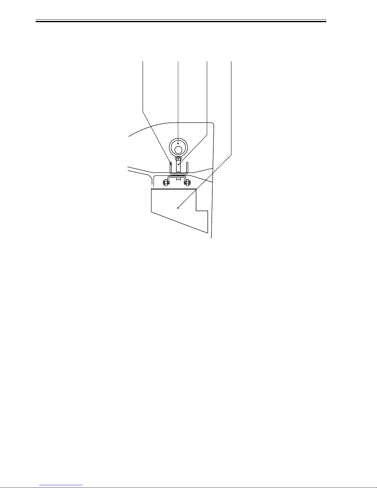
1.2.1 Removing the Stapler Unit ... 3-7
1.2.2 Adjusting the Stapler Phase . 3-8
1.2.3 Adjusting the Phase of the Gear
in the Saddle Unit ............... 3-13
1.2.4 Removing the Saddle Unit . 3-14
1.2.5 Removing the Processing
Tray Assembly ................... 3-16
1.2.6 Removing the Paddle
Assembly ........................... 3-18
1.2.7 Removing the Staple/Fold
Drive Unit .......................... 3-20
1.2.8 Removing the Feed Motor
Unit .................................... 3-24
1.2.9 Removing the Feed Roller .. 3-24
1.2.10 Removing the Stack delivery
roller (upper) ...................... 3-26
1.2.11 Removing the Paddle ......... 3-28
1.2.12 Removing the Stack delivery
roller (lower)/Delivery Belt 3-30
1.3 PCBs ........................................ 3-32
1.3.1 Removing the Finisher
Controller PCB .................. 3-32
1.3.2 Removing the Slide Home
Position PCB ..................... 3-33
2 Puncher Unit (option)........................ 3-35
2.1 Puncher Driving System .......... 3-35
2.1.1 Removing the Punch Motor 3-35
2.1.2 Removing the Horizontal
Registration Motor ............. 3-35
2.1.3 Removing the Punch Unit .. 3-36
2.2 PCBs ........................................ 3-38
2.2.1 Removing the Punch Controller
PCB ................................... 3-38
2.2.2 Removing the Photosensor
PCB ................................... 3-39
2.2.3 Removing the LED PCB .... 3-40
2.2.4 Removing the Waste-Full
Photosensor PCB ............... 3-41
2.2.5 Removing the Waste Full
LED PCB ........................... 3-42

CONTENTS
CHAPTER 4 MAINTENANCE AND INSPECTION
1 Periodically Replaced Parts ................. 4-1
1.1 Finisher/Saddle Unit ................... 4-1
1.2 Puncher Unit (option) ................. 4-1
2 Consumables and Durables ................. 4-2
2.1 Saddle/Finisher Unit ................... 4-2
3 Scheduled Maintenance ....................... 4-2
CHAPTER 5TROUBLESHOOTING
1 Standards and Adjustments ................. 5-1
1.1 Electrical System
(finisher/saddle unit) ................... 5-1
1.1.1 Adjusting the Folding
Position ................................ 5-1
1.1.2 Adjusting the Middle 2-Point
Stapling Position .................. 5-3
1.2 Electrical System
(puncher unit; option) ................. 5-4
1.2.1 Adjusting the Punch Hole
Position ................................ 5-4
1.2.2 Adjusting the Sensor Output 5-4
1.2.3 Registering the Number of
Punch Hole .......................... 5-5
1.2.4 After Replacing the EEP-ROM
(IC1002) .............................. 5-6
2 Arrangement of Electric Components..5-8
2.1 Finisher/Saddle Unit ................... 5-8
2.1.1 Sensors, Microswitches, and
Clutch ................................... 5-8
2.1.2 Motor PCBs ....................... 5-10
2.2 Puncher Unit (option) ............... 5-12
2.2.1 Sensors .............................. 5-12
2.2.2 Motors ............................... 5-13
2.2.3 PCBs.................................. 5-14
3 LEDs and Check Pins by PCB.......... 5-15
3.1 Finisher Controller PCB ........... 5-15
3.2 Punch Controller PCB .............. 5-16
4 Troubleshooting ................................ 5-17
4.1 Troubleshooting
(finisher/saddle unit) ................. 5-17
4.1.1 C0440, communication
error ................................... 5-17
4.1.2 C8390, Finisher Unit Back-Up
Memory Fault
(detail code: 10) .................. 5-17
4.1.3 C8010, Feed Motor Fault (detail
code: 01/02) ....................... 5-18
4.1.4 C8300, Delivery Motor Fault
(detail code: 01/02) ............. 5-18
4.1.5 C8320, Alignment Motor (Rear)
Fault (detail code: 01/02) .... 5-19
4.1.6 C8340, Staple/fold Motor Fault
(detail code: 01/02) ............. 5-19
4.1.7 C8340, Staple/Fold Motor Fault
(detail code: 03) .................. 5-20
4.1.8 C8340, Staple/Fold Motor Fault
(detail code: 01/02) ............. 5-20
4.1.9 C8340, Staple/Fold Motor Fault
(detail code: 03) .................. 5-21
4.1.10 C8360, Slide Motor Fault
(detail code: 01/02) ............. 5-21
4.1.11 C8330, Alignment Motor (front)
Fault (detail code: 01/02) .... 5-22
4.1.12 C8140, Shift Motor Fault (detail
code: 01) ............................ 5-22
4.1.13 C8140, Shift Motor Fault
(detail code: 02) .................. 5-23
4.1.14 C8140, Shift Motor Fault
(detail code: 03) .................. 5-23
4.1.15 C8370, Paddle Motor Fault
(detail code: 01/02/03/04) ... 5-24
4.2 Troubleshooting (puncher unit,
option) ...................................... 5-25
4.2.1 C8430, Communication
Faulty ................................. 5-25

CONTENTS
4.2.2 C8460, Puncher Back-UP
Memory Fault
(detail code: 20) .................. 5-25
4.2.3 C8480, Puncher Unit Power
Supply Fault (detail code:20)
........................................... 5-25
4.2.4 C8410, Punch Motor Fault
(detail code: 01/02) ............. 5-26
4.2.5 C8450 Punch Sensor (horizontal
registration) Fault (detail code:
01 through 05) ................... 5-26
4.2.6 C8470, Punch sensor (waste
full) Fault (detail code: 06) . 5-27
APPENDIX
1 General Timing Chart ......................... A-1
1.1 Finisher Unit ............................. A-1
1.2 Saddle Unit ................................ A-2
1.3 Puncher Unit (option) ................ A-3
2 Signals and Abbre viations.................. A-5
2.1 Finisher Saddle Unit.................. A-5
2.2 Puncher Unit (option) ................ A-7
3 Finisher/Saddle Unit General Circuit
Diagram.............................................. A-9
3.1 Finisher Controller PCB (1/8) . A-10
3.2 Finisher Controller PCB (2/8) . A-11
3.3 Finisher Controller PCB (3/8) . A-12
4.2.7 C8420, Horizontal Registration
Motor Fault
(detail code: 01/02) ............. 5-27
5 Self Diagnosis ................................... 5-28
5.1 Outline ...................................... 5-28
5.2 Errors ....................................... 5-28
5.2.1 Finisher/Saddle Unit .......... 5-28
5.2.2 Puncher Unit (option) ........ 5-31
5.3 Alarm ................................. 5-32
5.3.1 Finisher/Saddle Unit .......... 5-32
5.3.2 Puncher Unit (option) ........ 5-33
5.4 Host Machine I/O Display ....... 5-34
5.4.1 Finisher/Saddle Unit .......... 5-34
5.4.2 Puncher Unit (option) ........ 5-38
3.4 Finisher Controller PCB (4/8) . A-13
3.5 Finisher Controller PCB (5/8) . A-14
3.6 Finisher Controller PCB (6/8) . A-15
3.7 Finisher Controller PCB (7/8) . A-16
3.8 Finisher Controller PCB (8/8) . A-17
4 Puncher Unit General Circuit
Diagram............................................ A-18
4.1 Punch Controller PCB............. A-19
4.2 LED PCB ................................ A-20
4.3 Photosensor PCB .................... A-21

CHAPTER 1
GENERAL DESCRIPTION

CHAPTER 1 GENERAL DESCRIPTION
1 Features
a. Through-type stapler
Adoption of a through-type stapler allows a stapler to carry out saddle stitching.
b. Three different auto stapling positions
Three different stapling positions (front 1-point stapling, rear 1-point stapling, and middle
2-point stapling) are supported.
c. Saddle stitching
A maximum of ten sheets of paper can be delivered with them stapled and folded in the
middle.
d. Punch mechanism (option).
Installation of a puncher unit enables punching holes in sheets before delivery (64 to 90 g/
2
paper; no transparency).
m
1-1

CHAPTER 1 GENERAL DESCRIPTION
2 Specifications
2.1 Specifications
2.1.1 Finisher/Saddle Assembly
Item
Stacking
Feed reference
Stack paper size
Paper weight
Mode
Stack height (Note 1)
Mixed stack
Paper detection
Control panel
Specifications
2 locations
(1 ) Delivery Tray (descending type; 1 tray)
Face-down
(2 ) Bind Tray (fixed type)
Center reference
A3, A4, A4R, A5, A5R, B4, B5, B5R, 297mm
× 432mm (11” × 17”), LGL, LTR, LTRR,
STMT, STMTR
Finisher assembly: 64 to 90 g/m
Saddle Assembly: 64 to 90 g/m
Non-sort stack
Sort stack
Staple stack
Bind stack
Non-Sort Staple
2
2
Large-size: 500 sheets
Small-size: 1000 sheets (Note 2)
Staple Sort
Large-size: 30 sets or 500 sheets
Small-size: 30 sets or 1000 sheets
Folded stack
Stack of 6 to 10 sheets: 10 sets
Stack of 1 to 5 sheets: 20 sheets
Size mix: 500 sheets (Note 3)
Staple mix: 30 sheets (same paper configuration)
Delivery tray: No
Bind tray: Yes
No
Remarks
Large-size: A3, B4,
279mm × 432mm
(11” × 17”), LGL
Note 1:
The number of sheets is computed based on 80 g/m
Note 2:
Alignment is not guaranteed if the stack consists of 750 sheets or more.
Note 3:
Alignment is not guaranteed if the stack consists of sheets of different sizes.
1-2
2
paper.

CHAPTER 1 GENERAL DESCRIPTION
Item
Display
Size
Weight
Power supply
Maximum power consumption
Stapling
Stapling position
Stapling thickness
Staple supply
Staples
Staple detection
Stapling size
Manual stapling
Folding method
Folding mode
Folding position
Saddling size
Specifications
No
665 (W) × 615 (D) × 555 (H) mm /
26.18(W) × 24.21(D) × 21.85(H) in
27 kg / 59.40 lb (approx.)
24 VDC from host machine
At standby: 13 W
In operation: 84 W (staple sort)
Rotary cam type
See F01-201-01.
Finisher
Large-size: 25 sheets
Small-size: 50 sheets
Saddle: 10 sheets
Cartridge of special staples (5000
staples)
Special staples
Yes (nearly empty: 40 remaining staples)
Front 1-Point Stapling:
A3, A4R, B4, 279 mm × 432 mm (11” ×
17”), LGL, LTRR
Rear 1-Point Stapling:
A3, A4, A4R, B4, B5, 279 mm × 432
mm (11” × 17”), LGL, LTR, LTRR
Middle 2-Point Stapling:
A3, A4, A4R, B4, B5, 279 mm × 432
mm (11” × 17”), LGL, LTR, LTRR
Middle 2-Point Stapling:
A3, A4R, B4, 279 mm × 432 mm (11” ×
17”), LTRR
None
Roller contact
Double-folding (single-sheet non-stapling available)
Middle of sheet
A3, A4R, B4, 279 mm × 432 mm (11” ×
17”), LTRR
Remarks
(excl. installing kit)
(80 g/m
(80 g/m
(80 g/m
With the saddle in use.
Requires a margin of
±5mm / ±0.2in from the
middle of the sheet as a
middle margin.
No special paper.
2
paper)
2
paper)
2
paper)
T01-201-01
1-3
CHAPTER 1 GENERAL DESCRIPTION
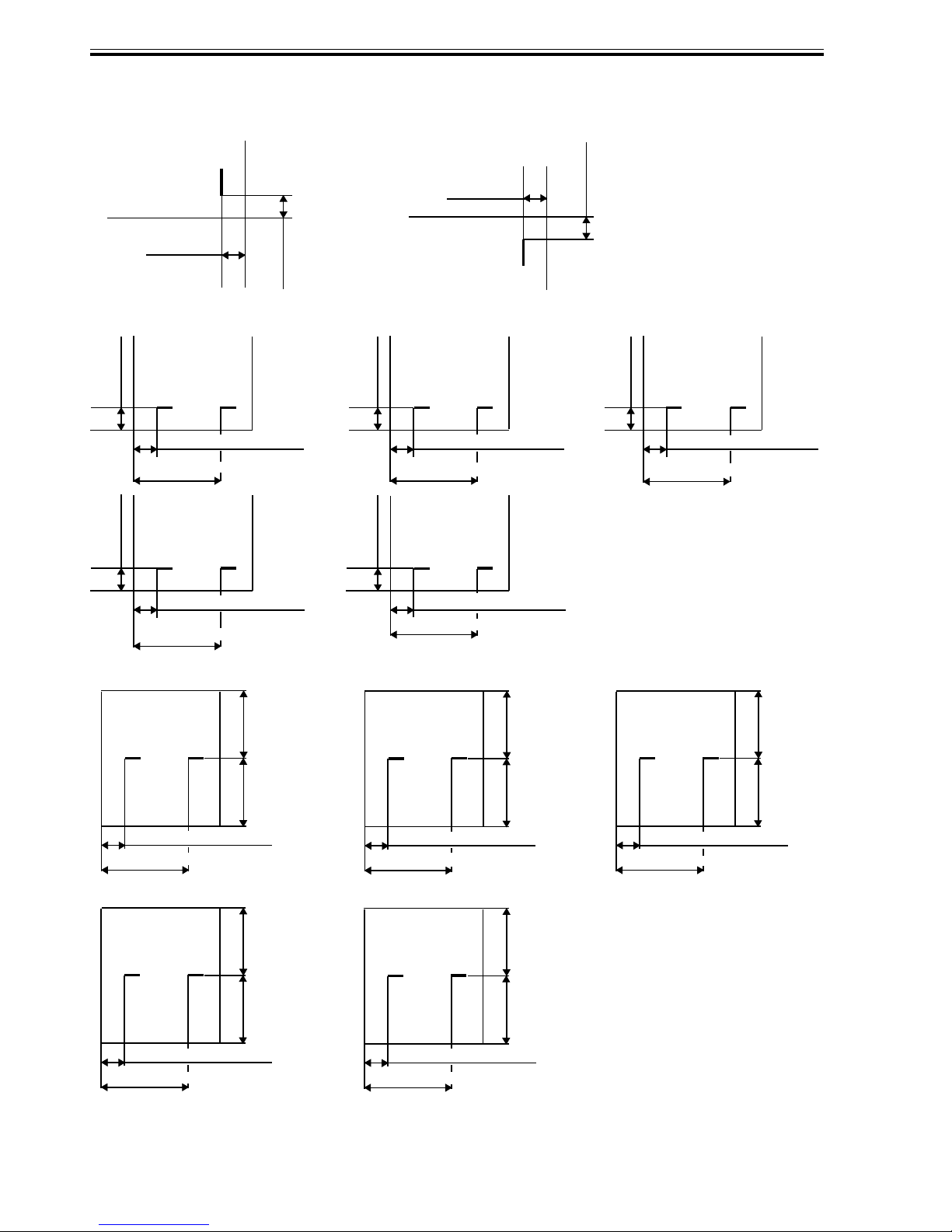
Staple Position
Front 1-point stapling
5±2 mm /
0.2±0.08 in
Middle 2-point stapling
A3 or A4 A4R
5±2 mm /
0.2±0.08 in
82±4 mm / 3.23±0.16 in
202±4 mm / 7.95±0.16 in
279×432 mm
×
17")
(11"
5±2 mm /
0.2±0.08 in
or LTR
5±2 mm /
0.2±0.08 in
Rear 1-point stapling
5±2 mm /
0.2±0.08 in
5±2 mm /
0.2±0.08 in
39±4 mm / 1.54±0.16 in 62±4 mm / 2.44±0.16 in
159±4 mm / 6.26±0.16 in
LGL or LTRR
5±2 mm /
0.2±0.08 in
5±2 mm /
0.2±0.08 in
5±2 mm /
B4 or B5
0.2±0.08 in
182±4 mm / 7.17±0.16 in
73±4 mm / 2.87±0.16 in
193±4 mm / 7.6±0.16 in
Middle 2-point stapling (w/ saddle in use)
A3
82±4 mm / 3.23±0.16 in
202±4 mm / 7.95±0.16 in
[χ1-χ2]≤1 mm
279 mm×432 mm
×
17")
(11"
χ1χ2
39±4 mm / 1.54±0.16 in
159±4 mm / 6.26±6.16 in
[χ1-χ2]≤1 mm
χ1χ2
42±4 mm / 1.65±0.16 in
162±4 mm / 6.38±0.16 in
A4R
LTRR
χ1χ2
χ12
B4
62±4 mm / 2.44±0.16 in
182±4 mm / 7.17±0.16 in
[χ1-χ2]≤1 mm
χ1χ2
73±4 mm / 2.87±0.16 in
193±4 mm / 7.6±0.16 in
[χ1-χ2]≤1 mm
1-4
42±4 mm / 1.65±0.16 in
162±4 mm / 6.38±0.16 in
[χ1-χ2]≤1 mm
F01-201-01
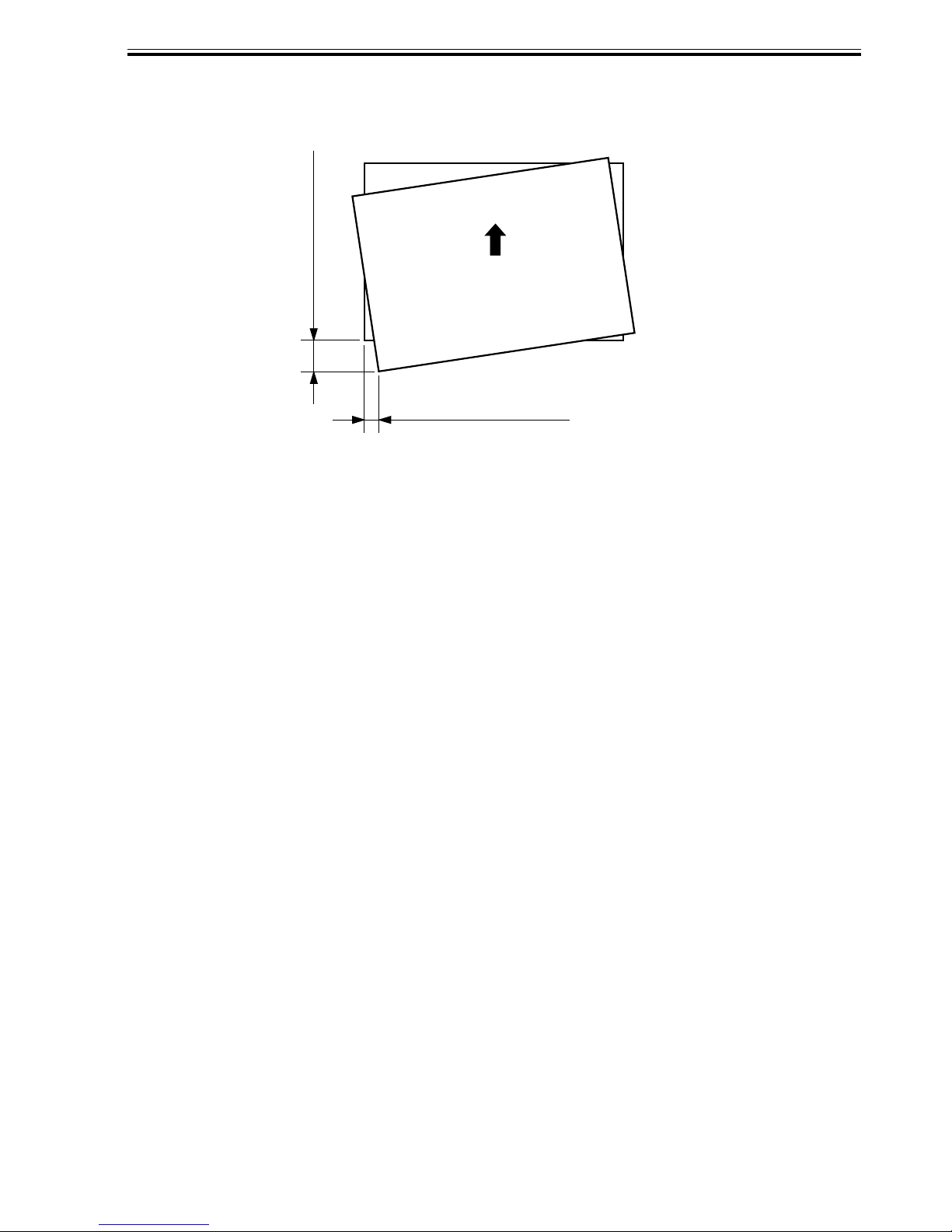
Stacked Paper Alignment
50 mm / 1.97 in max.
CHAPTER 1 GENERAL DESCRIPTION
Delivery direction
20 mm / 0.79 in max.
F01-201-02
1-5

CHAPTER 1 GENERAL DESCRIPTION
2.1.2 Puncher unit (option)
Item
Punching method
Paper size
Paper weight
Punch hole diameter
Punch waste
Size
Weight
Power supply
Power consumption
Specifications
Reciprocating method
(sequential processing method)
2-hole (Puncher Unit-J1):
A3, A4, A4R, B4, B5, B5R
2-/3-hole (Puncher Unit-K1):
2-hole/LGL, LTRR
3-hole/279 × 432 mm (11”×17”), LTR
4-hole (Puncher Unit-G1/-H1):
A3, A4
64 g/m
2-hole (Puncher Unit-J1):
6.5 mm / 0.26 in
2-/3-hole (Puncher Unit-K1):
2-hole 8.0 mm / 0.31 in
3-hole 8.0 mm / 0.31 in
4-hole (Puncher Unit-G1/-H1):
6.5 mm / 0.26 in
2-hole (Puncher Unit-J1):
3000 sheets
2-/3-hole (Puncher Unit-K1):
2-hole/1500 sheets
3-hole/1500 sheets
4-hole (Puncher Unit-G1/H1) :
1500 sheets
90 (W) × 560 (D) × 170 (H) mm /
3.54 (W) × 22.05 (D) × 6.69 (H) in
2.5 kg / 5.5 lb (approx.)
24 VDC from finisher unit.
Standby: 2 W max.
Operating: 21 W max (punching)
2
~ 90 g/m
Remarks
2
No transparencies.
64 g/m
75 g/m
75 g/m
80 g/m
2
paper
2
paper
2
paper
2
paper
1-6
T01-201-02
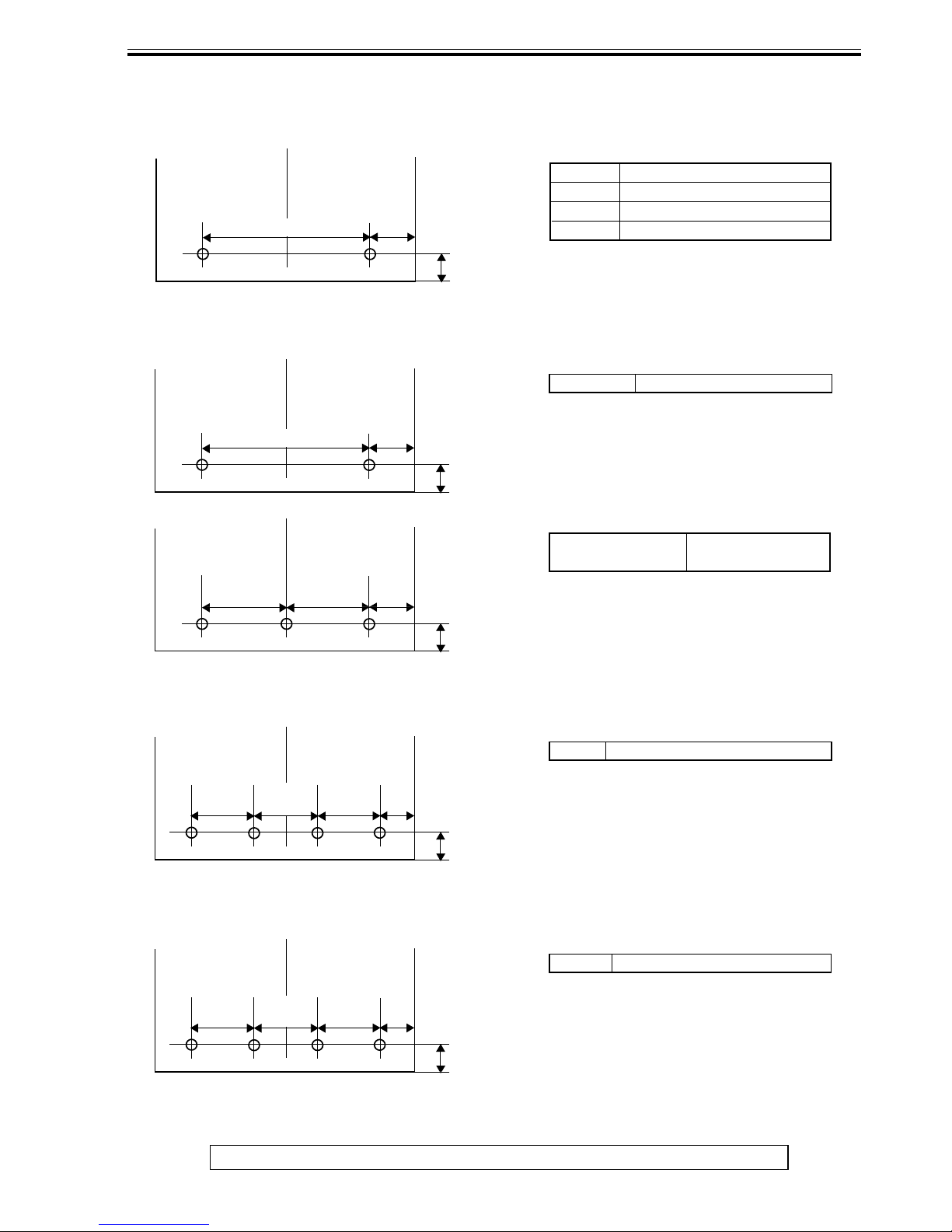
Hole position
[1] 2-Hole (Puncher Unit-J1)
80±1 mm / 3.15±0.04 in
[2] 2-/3-Hole (Puncher Unit-K1)
χ1
CHAPTER 1 GENERAL DESCRIPTION
χ1
A3/A4 108.5±3 mm / 4.27±0.12 in
B5/B4 88.5±3 mm / 3.48±0.12 in
A4R 65±3 mm / 2.56±0.12 in
B5R 51±3 mm / 2.01±0.12 in
12±3 mm /
0.47±0.12 in
χ1
LGL/LTRR 73±3 mm / 2.87±0.12 in
70±1 mm / 2.76±0.04 in
108±1 mm /
4.25±0.04 in
108±1 mm /
4.25±0.04 in
[3] 4-Hole (Puncher Unit-G1)
80±1 mm /
3.15±0.04 in
80±1 mm /
3.15±0.04 in
80±1 mm /
3.15±0.04 in
χ1
χ1
12±3 mm /
0.47±0.12 in
χ1
279 mm×432 mm
(11"×17")/LTR
31.5±3 mm /
1.24±0.12 in
12±3 mm /
0.47±0.12 in
χ1
A3/A4 28.5±3 mm / 1.12±0.12 in
χ
1
12±3 mm /
0.47±0.12 in
[4] 4-Hole (Puncher Unit-H1)
21±1 mm /
0.83±0.04 in
70±1 mm /
2.76±0.04 in
The above specifications are subject to change for product improvement.
21±1 mm /
0.83±0.04 in
χ1
A3/A4 92.5±3 mm / 3.64±0.12 in
χ
1
12±3 mm /
0.47±0.12 in
F01-201-03
1-7
CHAPTER 1 GENERAL DESCRIPTION
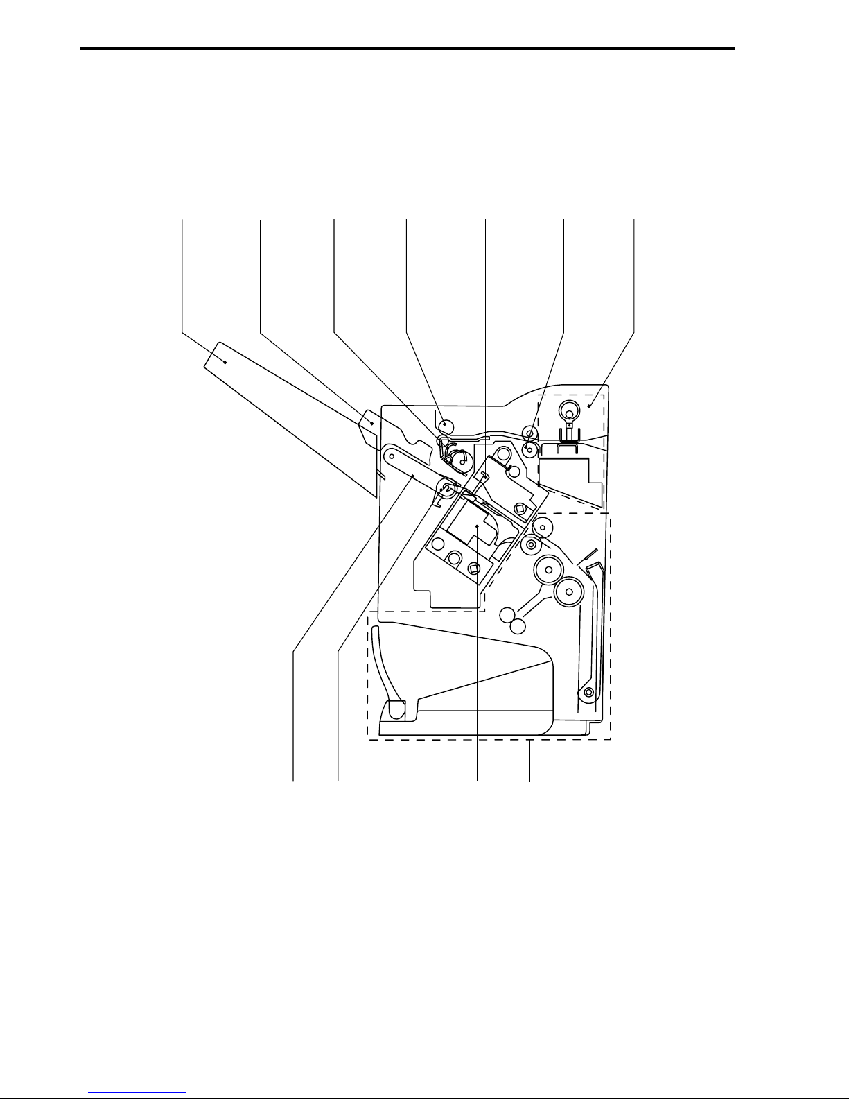
3 Names of Par ts
3.1 Cross Section
3.1.1 Finisher Unit
[1]
[2]
[3] [7][5][4] [6]
[1] Delivery tray
[2] Aligning plate (front, rear)
[3] Paddle
[4] Delivery roller
[5] Processing tray stopper
1-8
[8]
[9]
F01-301-01
[10]
[11]
[6] Feed roller
[7] Puncher unit (option)
[8] Delivery belt
[9] Stack delivery roller
[10] Stapler
[11] Saddle unit
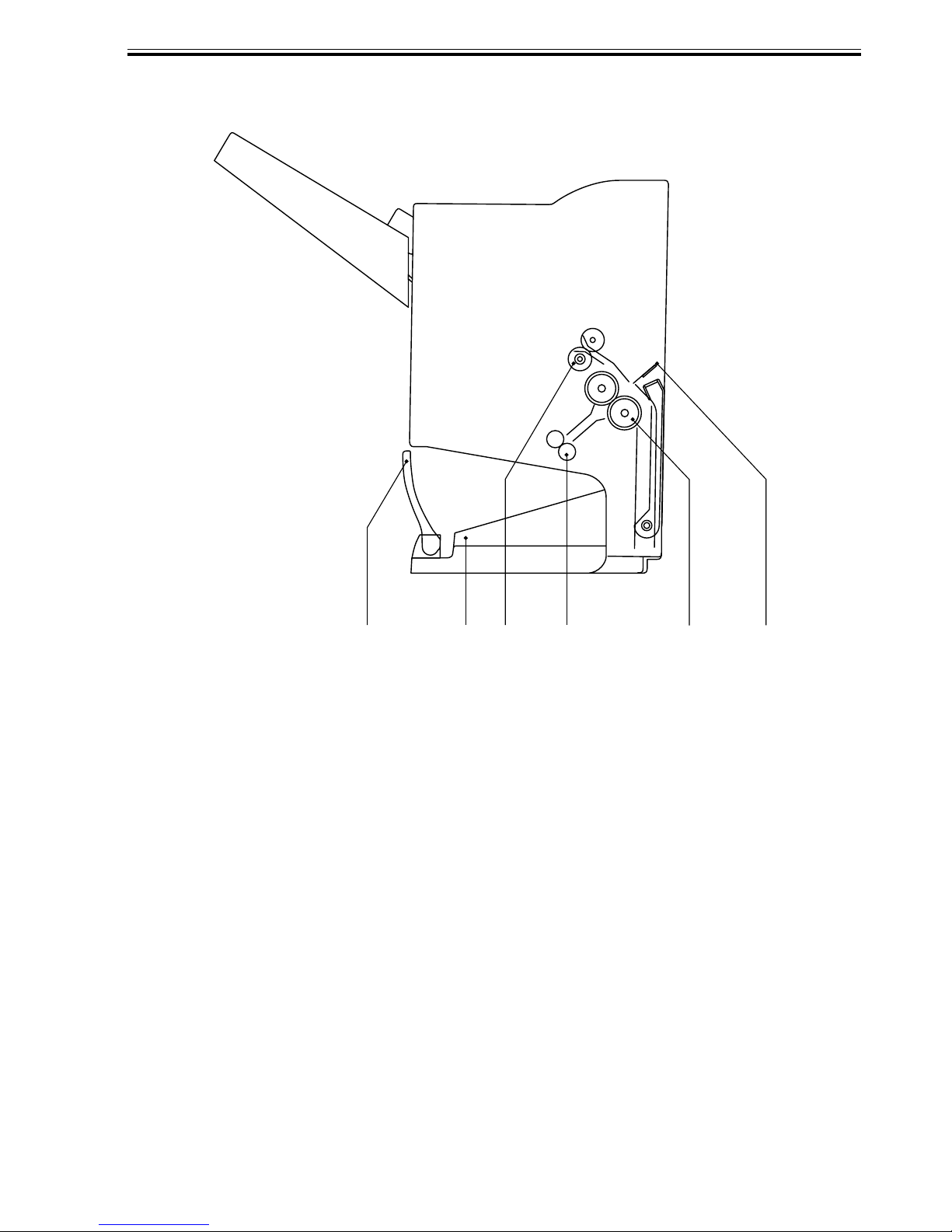
3.1.2 Saddle Unit
CHAPTER 1 GENERAL DESCRIPTION
[1] Bind stopper
[2] Bind tray
[3] Stack feed roller
[1]
[3]
[4] Bind delivery roller
[5] Paper fold roller
[6] Paper pushing plate
F01-301-02
[4][2]
[5]
[6]
1-9
CHAPTER 1 GENERAL DESCRIPTION
3.1.3 Puncher Unit (option)
[2]
[3][1]
[4]
[1] Die
[2] Cam
[3] Hole puncher (Punch blade)
[4] Punch waste case
F01-301-03
1-10

CHAPTER 1 GENERAL DESCRIPTION
4 Routine Maintenance by the User
No.
1
2
Item
Staple cartridge (replacement)
Punch waste removal (optional)
T01-400-01
Timing
When prompted (indicator on host
machine control panel)
When prompted (indicator on host
machine control panel)
As of February, 2001
1-11

CHAPTER 2
OUTLINE OF OPERATION
CHAPTER 2 OUTLINE OF OPERATION
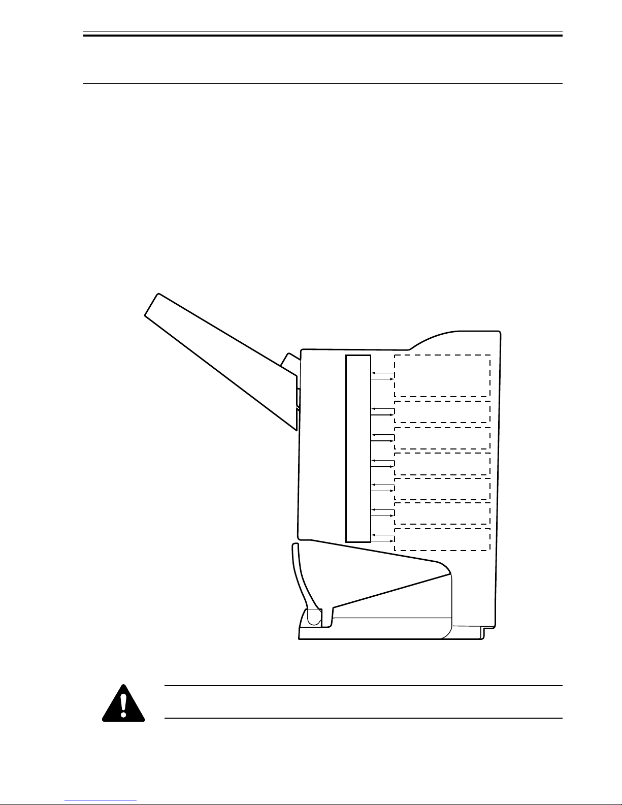
1 Basic Operations
1.1 Specifications
The finisher serves to deliver sheets coming from its host machine. The mode of delivery
may be non-sort stack, job offset*, or staple delivery.
The saddle unit built into the finisher is used to fold a stack of sheets coming from the fin-
isher unit in half for delivery.
All these operations are controlled by various commands sent by the host machine in addi-
tion to the commands from the finisher controller PCB.
The puncher unit (option) is designed for installation to the pickup assembly of the finisher,
and is used to punch holes in sheets coming from the host machine.
The above operations are controlled with various commands from the finisher controller
PCB as well as the commands from the punch controller PCB.
Puncher unit drive
system (puncher unit;
option)
Alignment drive system
Stapler drive system
Delivery drive system
Control system
Feed drive system
Tray drive system
Saddle unit
drive system
The position of delivery is shifted to the front/rear for each stack to assist
sorting.
F02-101-01
2-1
CHAPTER 2 OUTLINE OF OPERATION
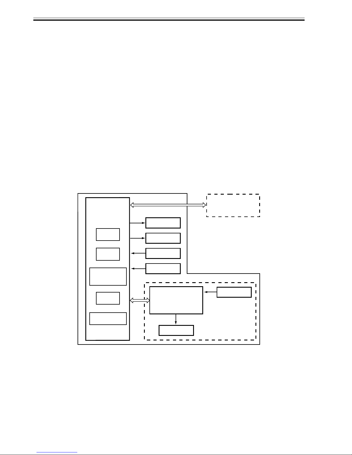
1.2 Outline of the Electrical Circuitry
The sequence of finisher operations is controlled by the finisher controller PCB. The finisher controller PCB is a 16-bit microprocessor (CPU), and is also used for combination with
the host machine (serial).
The finisher controller PCB drive motors and other loads in response to the various commands from the host machine. It also communicates such data as on the states of various sensors and switches to the host machine by way of the serial communication line.
The ICs mounted to the finisher controller PCB have the following functions:
• IC13 (CPU)
Controls sequence of operations.
• IC12 (EEP-ROM)
Backs up adjustment settings.
• IC6 (EP-ROM)
Stores sequence programs.
F02-102-01 shows the flow of signals between finisher and options controller:
• IC11 (communication IC)
Communicates with the host machine.
• IC1 (regulator IC)
Generates 5 V.
Finisher unit
Finisher
controller
PCB
IC13
CPU
IC12
EEP-ROM
IC11
Communica-
tion IC
IC6
EP-ROM
IC1
Regulator IC
Host machine DC
controller PCB
CPU
Motor
Clutch
Switch
Sensor
Puncher unit (option)
Sensor
Punch controller
PCB
Motor
2-2
F02-102-01
CHAPTER 2 OUTLINE OF OPERATION
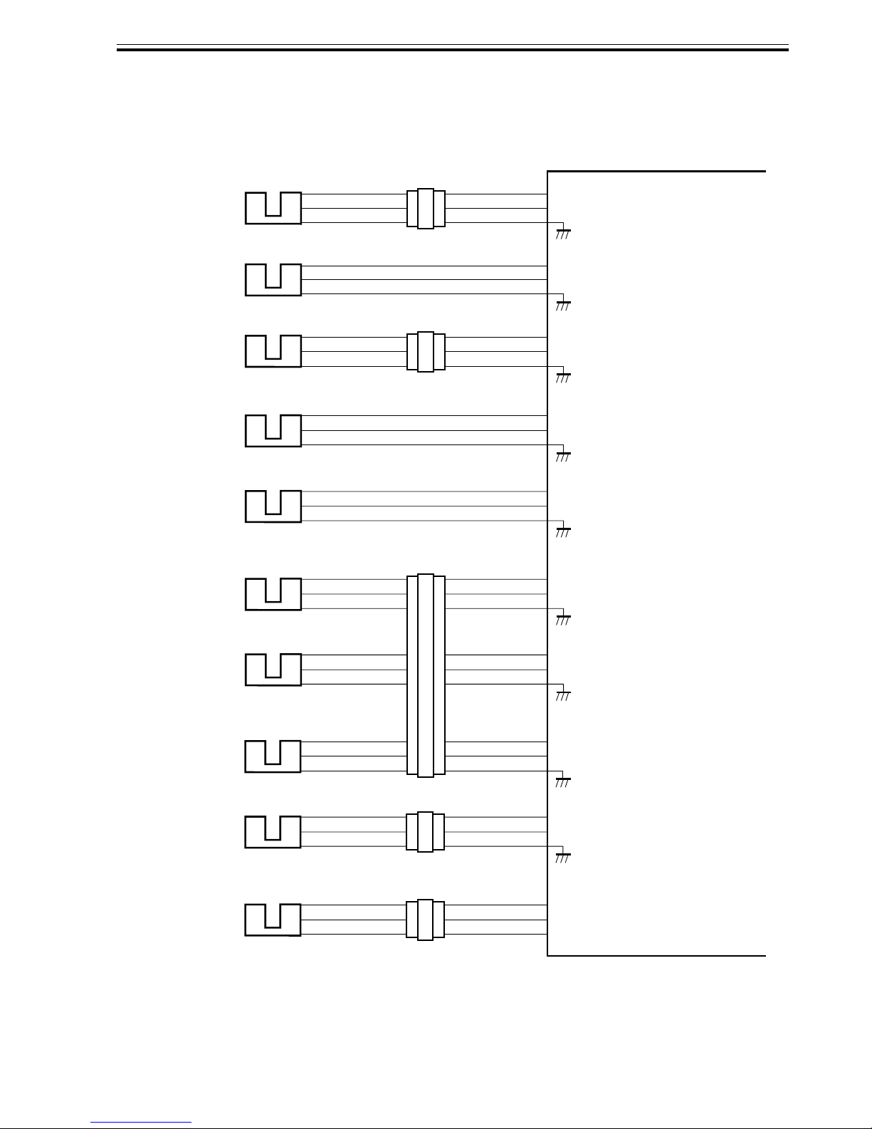
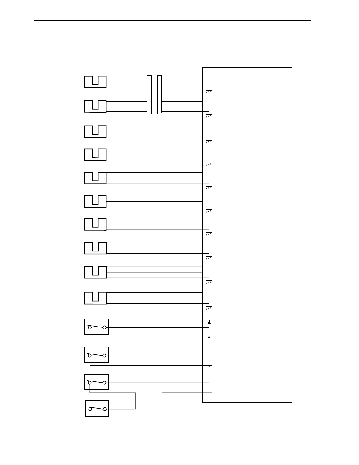
1.3 Inputs to and Outputs from the Finisher Controller PCB
1.3.1 Inputs to the Finisher Controller PCB (1/2)
Finisher controller PCB
Inlet sensor
Paddle home
position sensor
PI1
PI2
CN44-3
CN51-1
-1
-2
-3
-2
CN43-1
-3
-2
CN42-3
-1
-2
CN16-10
-12
-11
CN9-1
-3
-2
+5 V
ENT_S
+5 V
PDL_HP
When the sensor
detects paper, ‘1’ .
When the paddle is at
home position, ‘1’.
Swing guide
home position
sensor
Aligning plate
home position
sensor (front)
Aligning plate
home position
sensor (rear)
Processing
tray sensor
Delivery belt
home position
sensor
Tray paper sensor
PI3
PI4
PI5
PI6
PI7
PI8
CN55-3
CN23-3
CN36-3
CN30-3
CN31-3
CN32-3
-1
-2
-1
-2
-1
-2
-1
-2
-1
-2
-1
-2
CN54-1
-3
-2
CN29-1
-3
-2
-4
-6
-5
-7
-9
-8
CN53-3
CN28-9
-1
-2
-7
-8
-6
-4
-5
-3
-1
-2
CN9-7
CN4
CN5-13
-15
-14
CN5-1
+5 V
-9
BDL_ROL_HP
-8
+5 V
-3
F JOG_HP
-2
+5 V
R JOG_HP
+5 V
-3
ADJ_TRAY_S
-2
-4
+5 V
-6
EJCT_BLT_HP
-5
-7
+5 V
-9
TRY_EMPS
-8
When the swing guide
is at home position, ‘1’.
When the aligning
plate (front) is at
home position, ‘1’.
When the aligning
plate (rear) is at
home position, ‘1’.
When the sensor
detects paper, ‘1’.
When the delivery belt
is at home position, ‘1’.
When paper is present
on the tray, ‘1’.
Paper surface
PI9
sensor
PI10
Folding position
sensor
CN35-3
CN39-3
-1
-2
-2
-1
CN34-1
-3
-2
CN38-1
-2
-3
CN33-3
-1
-2
CN37-9
-8
-7
F02-103-01
CN5-10
-12
-11
CN16-1
-2
-3
+5 V
LVL_S
+5 V
BIND_P
BIND_L
When the paper
surface is detected,
‘1’.
When paper is
detected, ‘0’.
When LED is lit, ‘1’.
2-3
CHAPTER 2 OUTLINE OF OPERATION
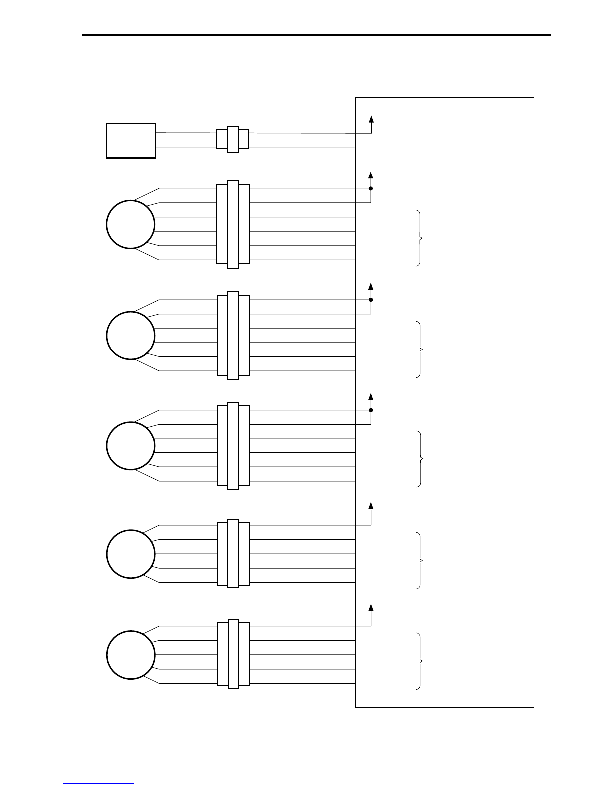
1.3.2 Inputs to the Finisher Controller PCB (2/2)
Finisher controller PCB
Folding home
position sensor
Stack feed roller
(upper) home
position sensor
Bind tray sensor
Staple/fold motor
clock sensor
Shift upper limit
sensor
Shift lower limit
sensor
Shift motor clock
sensor
Front door sensor
PI11
PI12
PI13
PI14
PI15
PI16
PI17
PI22
CN40-3
CN41-3
CN47-3
CN52-1
CN50-3
CN49-3
CN48-3
CN25-3
-1
-2
-1
-2
-1
-2
-2
-3
-1
-2
-1
-2
-1
-2
-1
-2
CN38-4
-6
CN37-6
-5
-7
-9
-8
CN16-4
-4
-5
-3
-1
-2
CN15-1
CN15-10
CN15-7
CN15-4
CN9-6
-12
-11
CN4-7
+5 V
-6
BIND_HP
-5
-7
+5 V
-9
BIND_ROL_HP
-8
+5 V
-3
BIND_EMPS
-2
+5 V
-5
BIND_CLK
-4
+5 V
SIFT_UPLMT
+5 V
-9
SIFT_DNLMT
-8
+5 V
-6
SIFT_CLK
-5
+5 V
-9
FDOOR_S
-8
When at folding home position, ‘0’.
When the stack feed roller
(upper) is at home position, ‘1’.
When the sensor
detects paper, ‘1’.
When the staple/fold motor is
rotating, alternates between
‘1’ and ‘0’.
When the tray is at the
upper limit, ‘1’.
When the tray is at the
lower limit, ‘1’.
While the shift motor
is rotating, alternates
between ‘1’ and ‘0’.
When the front door
is open, ‘1’.
Upper cover sensor
Full stack sensor
Joint switch
Front door switch
Stapler safety
switch
Stapler safety
switch(F)
PI23
PI24
MS2
N. O.
MS1
N. O.
MS3
N. O.
MS4
N. O.
CN24-3
CN73-3
CN69-2
CN68-2
CN66-2
CN75-2
CN4-4
-1
-2
CN19-1
-1
-2
CN8-6
-1
CN8-4
-1
CN8-2
-1
-1
+5 V
-6
TOPCOV_S
-5
+5 V
-3
PAPER_F
-2
+24 VP
-5
-3
-1
JOINT SW
FRONT SW
STPLSAFE SW
When the upper cover
is open, ‘1’.
When the paper is
full, ‘1’.
When connected to
the host machine, ‘1’.
When the front
door is closed, ‘1’.
When the swing
guide is closed, ‘1’.
2-4
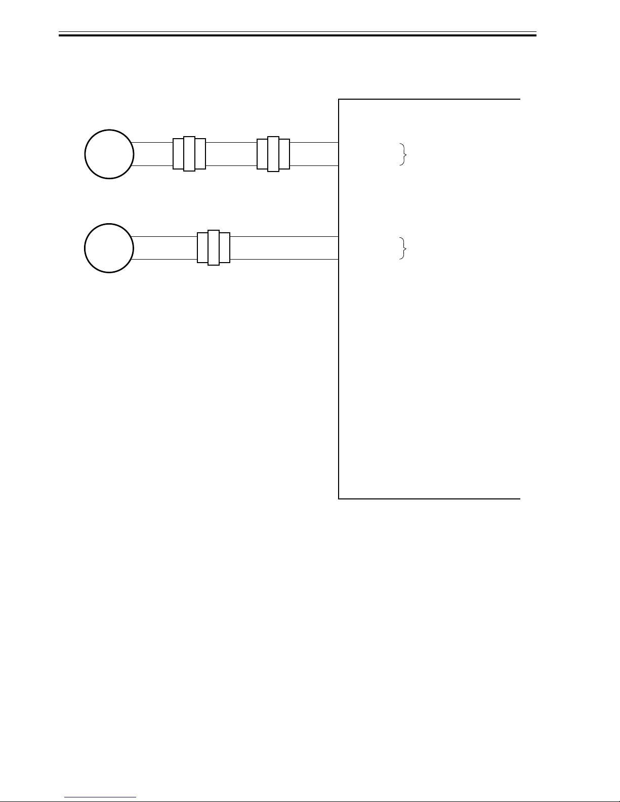
CHAPTER 2 OUTLINE OF OPERATION
1.3.3 Outputs from the Finisher Controller PCB (1/2)
Finisher controller PCB
Binding clutch
CL1
Feed motor
M1
Paddle motor
M2
Delivery motor
M3
+24 V
-1
-2
-6
-5
-4
-3
-2
-1
-6
-5
-4
-3
-2
-1
-6
-5
-4
-3
-2
-1
CN72
CN56
CN57
CN59
-2
-1
-1
-2
-3
-4
-5
-6
-1
-2
-3
-4
-5
-6
-1
-2
-3
-4
-5
-6
CN18-1
CN10-1
CN10-7
-10
-11
-12
CN13-1
-2
B_CLU
+24 V
-2
-3
FEEDMTR_A
-4
FEEDMTR_*A
-5
FEEDMTR_B
-6
FEEDMTR_*B
+24 V
-8
-9
PDLMTR_A
PDLMTR_*A
PDLMTR_B
PDLMTR_*B
+24 V
-2
-3
EJCTMTR_A
-4
EJCTMTR_*A
-5
EJCTMTR_B
-6
EJCTMTR_*B
When the drive is transmitted,
‘1’.
Switches between ‘1’ and
‘0’ according to the
direction of motor rotation.
Switches between ‘1’ and
‘0’ according to the
direction of motor rotation.
Switches between ‘1’ and
‘0’ according to the
direction of motor rotation.
Alignment motor
(front)
M4
Alignment motor
(rear)
M5
CN63-1
-2
-3
-4
-5
CN65-1
-2
-3
-4
-5
CN62-5
-4
-3
-2
-1
CN64-5
-4
-3
-2
-1
CN3-1
CN3-6
-10
F02-103-03
+24 V
-2
FJOGMTR_A
-3
FJOGMTR_*A
-4
FJOGMTR_B
-5
FJOGMTR_*B
+24 V
-7
RJOGMTR_A
-8
RJOGMTR_*A
-9
RJOGMTR_B
RJOGMTR_*B
Switches between ‘1’ and
‘0’ according to the
direction of motor rotation.
Switches between ‘1’ and
‘0’ according to the
direction of motor rotation.
2-5
CHAPTER 2 OUTLINE OF OPERATION
1.3.4 Outputs from the Finisher Controller PCB (2/2)
Shift motor
M6
Staple/fold motor
M7
-2
-1
CN70
-2
-1
-2
-1
CN71
-2
-1
-2
-1
CN70
-2
-1
CN6-1
CN6-3
SIFTMTR_1
-2
SIFTMTR_0
BINDMTR_1
-4
BINDMTR_0
Finisher controller PCB
Switches between ‘+’ and
‘–’ according to the
direction of motor rotation.
Switches between ‘+’ and
‘–’ according to the
direction of motor rotation.
2-6
F02-103-04
 Loading...