

Kyocera Mita DC-2560, DC-2060 Service Manual

SERVICE
MANUAL
Published in Oct. ’99
841AH110
DC-2060/2560
DC-2060/2560

Service
Manual
DC-2050/2560

CAUTION: DANGER OF EXPLOSION IF BATTERY IS INCORRECTLY REPLACED. REPLACE ONLY WITH THE SAME OR EQUIVALENT TYPE RECOMMENDED BY THE MANUFACTURER. DISPOSE OF USED BATTERIES
ACCORDING TO THE MANUFACTURER'S INSTRUCTIONS.
CAUTION: DOUBLE-POLE / NEUTRAL FUSING
ATTENTION: IL Y A DANGER D'EXPLOSION S'IL Y A REMPLACEMENT IN-
CORRECT DE LA BATTERIE. REMPLACER UNIQUEMENT AVEC UNE
BATTERIE DU MÊME TYPE OU D'UN TYPE RECOMMANDÉ PAR LE
CONSTRUCTEUR. METTRE AU RÉBUT LES BATTERIE USAGÉES
CONFORMÉMENT AUX INSTRUCTIONS DU FABRICANT.


Safety precautions
This booklet provides safety warnings and precautions for our service
personnel to ensure the safety of their customers, their machines as well
as themselves during maintenance activities. Service personnel are
advised to read this booklet carefully to familiarize themselves with the
warnings and precautions described here before engaging in
maintenance activities.
Safety warnings and precautions
Various symbols are used to protect our service personnel and
customers from physical danger and to prevent damage to their
property. These symbols are described below:
DANGER: High risk of serious bodily injury or death may result from
insufficient attention to or incorrect compliance with warning
messages using this symbol.
WARNING: Serious bodily injury or death may result from insufficient
attention to or incorrect compliance with warning messages
using this symbol.
CAUTION: Bodily injury or damage to property may result from
insufficient attention to or incorrect compliance with warning
messages using this symbol.
Symbols
The triangle (
) symbol indicates a warning including danger
and caution. The specific point of attention is shown inside
the symbol.
General warning.
Warning of risk of electric shock.
Warning of high temperature.
indicates a prohibited action. The specific prohibition is
shown inside the symbol.
General prohibited action.
Disassembly prohibited.
indicates that action is required. The specific action
required is shown inside the symbol.
General action required.
Remove the power plug from the wall outlet.
Always ground the copier.
1. Installation Precautions
WARNING
• Do not use a power supply with a voltage other than that specified.
Avoid multiple connections to one outlet: they may cause fire or electric
shock. When using an extension cable, always check that it is
adequate for the rated current. ...............................................................
• Connect the ground wire to a suitable grounding point. Not grounding
the copier may cause fire or electric shock. Connecting the earth wire
to an object not approved for the purpose may cause explosion or
electric shock. Never connect the ground cable to any of the following:
gas pipes, lightning rods, ground cables for telephone lines and water
pipes or faucets not approved by the proper authorities.........................
CAUTION:
• Do not place the copier on an infirm or angled surface: the copier may
tip over, causing injury. ...........................................................................
• Do not install the copier in a humid or dusty place. This may cause fire
or electric shock......................................................................................
• Do not install the copier near a radiator, heater, other heat source or
near flammable material. This may cause fire. .......................................
• Allow sufficient space around the copier to allow the ventilation grills to
keep the machine as cool as possible. Insufficient ventilation may
cause heat buildup and poor copying performance................................
• Always handle the machine by the correct locations when moving it. ....
• Always use anti-toppling and locking devices on copiers so equipped.
Failure to do this may cause the copier to move unexpectedly or
topple, leading to injury. ..........................................................................
• Avoid inhaling toner or developer excessively. Protect the eyes. If toner
or developer is accidentally ingested, drink a lot of water to dilute it in
the stomach and obtain medical attention immediately. If it gets into the
eyes, rinse immediately with copious amounts of water and obtain
medical attention.....................................................................................
• Advice customers that they must always follow the safety warnings and
precautions in the copier’s instruction handbook. ...................................
2. Precautions for Maintenance
WARNING
• Always remove the power plug from the wall outlet before starting
machine disassembly. ............................................................................
• Always follow the procedures for maintenance described in the service
manual and other related brochures. ......................................................
• Under no circumstances attempt to bypass or disable safety features
including safety mechanisms and protective circuits. .............................
• Always use parts having the correct specifications. ...............................
• Always use the thermostat or thermal fuse specified in the service
manual or other related brochure when replacing them. Using a piece
of wire, for example, could lead to fire or other serious accident............
• When the service manual or other serious brochure specifies a
distance or gap for installation of a part, always use the correct scale
and measure carefully. ...........................................................................
• Always check that the copier is correctly connected to an outlet with a
ground connection. .................................................................................

• Check that the power cable covering is free of damage. Check that the
power plug is dust-free. If it is dirty, clean it to remove the risk of fire or
electric shock. .........................................................................................
• Never attempt to disassemble the optical unit in machines using lasers.
Leaking laser light may damage eyesight...............................................
• Handle the charger sections with care. They are charged to high
potentials and may cause electric shock if handled improperly..............
CAUTION
• Wear safe clothing. Avoid wearing loose clothing or accessories such
as ties which may be caught in rotating sections....................................
• Use utmost caution when working on a powered machine. Keep away
from chains and belts..............................................................................
• Handle the fixing section with care to avoid burns as it can be
extremely hot..........................................................................................
• Check that the fixing unit thermistor, heat and press rollers are clean.
Dirt on them can cause abnormally high temperatures. .........................
• Do not remove the ozone filter, if any, from the copier except for
routine replacement. ...............................................................................
• Do not pull on the AC power cord or connector wires on high-voltage
components when removing them; always hold the plug itself...............
• Do not route the power cable where it may be stood on or trapped. If
necessary, protect it with a cable cover or other appropriate item. ........
• Treat the ends of the wire carefully when installing a new charger wire
to avoid electric leaks. ............................................................................
• Remove toner completely from electronic components. .........................
• Run wire harnesses carefully so that wires will not be trapped or
damaged.................................................................................................
• After maintenance, always check that all the parts, screws, connectors
and wires that were removed, have been refitted correctly. Special
attention should be paid to any forgotten connector, trapped wire and
missing screws. ......................................................................................
• Check that all the caution labels that should be present on the machine
according to the instruction handbook are clean and not peeling.
Replace with new ones if necessary.......................................................
• Handle greases and solvents with care by following the instructions
below: .....................................................................................................
· Use only a small amount of solvent at a time, being careful not to
spill. Wipe spills off completely.
· Ventilate the room well while using grease or solvents.
· Allow applied solvents to evaporate completely before refitting the
covers or turning the main switch on.
· Always wash hands afterwards.
• Never dispose of toner or toner bottles in fire. Toner may cause
sparks when exposed directly to fire in a furnace, etc..........................
• Should smoke be seen coming from the copier, remove the power
plug from the wall outlet immediately. ..................................................
3. Miscellaneous
WARNING
• Never attempt to heat the drum or expose it to any organic solvents
such as alcohol, other than the specified refiner; it may generate toxic
gas. .........................................................................................................

1AH
CONTENTS
I THEORY AND CONSTRUCTION SECTION
1-1 Specifications
1-1-1 Specifications DC 2560 .................................................................... 1-1-1
1-1-4 Specifications DC 2560 .....................................................................1-1-4
1-2 Handling Precautions
1-2-1 Drum ................................................................................................. 1-2-1
1-2-2 Developer and toner ......................................................................... 1-2-1
1-2-3 Dehumidifier ..................................................................................... 1-2-1
1-2-4 Copy paper ....................................................................................... 1-2-1
1-3 Mechanical Construction
1-3-1 Machine parts names and their functions ......................................... 1-3-1
1-3-2 Machine cross sections .................................................................... 1-3-4
1-3-3 Drive system..................................................................................... 1-3-6
1-3-4 Mechanical construction ................................................................. 1-3-10
II ELECTRICAL SECTION
2-1 Electrical Parts Layout
2-1-1 Electrical parts layout ....................................................................... 2-1-1
2-2 Detection of Paper Misfeeds
2-2-1 Paper misfeed detection ................................................................... 2-2-1
2-2-2 Paper misfeed detection conditions ................................................. 2-2-2
2-3 Operation of the PCB
2-3-1 Composite PCB ................................................................................. 2-3-1
2-3-2 Main PCB ....................................................................................... 2-3-11
2-3-3 Operation unit PCB ......................................................................... 2-3-18
III SET UP AND ADJUSTMENT SECTION
3-1 Installation
3-1-1 Unpacking and installation ............................................................... 3-1-1
3-1-2 Setting initial copy modes............................................................... 3-1-13
3-1-3 Installing the key counter (optional) ................................................ 3-1-14
3-1-4 Installing the cassette heater (optional) .......................................... 3-1-17
3-1-5 Installing the original size sensor (optional) ................................... 3-1-20
3-2 Simulation
3-2-1 Simulation ......................................................................................... 3-2-1
3-3 Assembly and Disassembly
3-3-1 Precautions for assembly and disassembly ..................................... 3-3-1
3-3-2 Paper feed section ........................................................................... 3-3-3
3-3-3 Main charging section .................................................................... 3-3-28
3-3-4 Exposure section ............................................................................ 3-3-33
3-3-5 Drum section .................................................................................. 3-3-72
3-3-6 Developing section ......................................................................... 3-3-76
3-3-7 Transfer and separation section ..................................................... 3-3-79
3-3-8 Cleaning section ............................................................................. 3-3-84
3-3-9 Paper conveying section ................................................................ 3-3-87
3-3-10 Fixing section ............................................................................... 3-3-90
3-3-11 Others ........................................................................................ 3-3-103
3-3-12 Special tray section (optional) .................................................... 3-3-108
3-3-13 Feedshift and duplex sections (optional).................................... 3-3-116

3-4 PCB Initial Setting
3-4-1 Replacing the main PCB .................................................................. 3-4-1
3-4-2 Adjustment-free variable resistors (VR) ........................................... 3-4-4
3-5 Self-diagnostics
3-5-1 Self diagnostic function .................................................................... 3-5-1
3-6 Troubleshooting
3-6-1 Image problems................................................................................ 3-6-1
3-6-2 Paper misfeeds .............................................................................. 3-6-14
3-6-3 PCB terminal voltages.................................................................... 3-6-21
3-6-4 Electrical problems ......................................................................... 3-6-32
3-6-5 Mechanical problems ...................................................................... 3-6-45
3-7 Appendixes
Timing chart No. 1 ...................................................................................... 3-7-1
Timing chart No. 2 ...................................................................................... 3-7-2
Timing chart No. 3 ...................................................................................... 3-7-3
Timing chart No. 4 ...................................................................................... 3-7-4
Timing chart No. 5 ...................................................................................... 3-7-5
Timing chart No. 6 ...................................................................................... 3-7-6
Timing chart No. 7 ...................................................................................... 3-7-7
Timing chart No. 8 ...................................................................................... 3-7-8
Composite PCB 1/3 (Power source section 1/2) ........................................... 3-7-9
Composite PCB 2/3 (Power source section 2/2) ......................................... 3-7-10
Composite PCB 3/3 (AVR/Fixing heater control section) ........................... 3-7-11
Backup PCB .............................................................................................. 3-7-12
Main PCB 1/
3
.............................................................................................................................
3-7-13
Main PCB 2/
3
.............................................................................................................................
3-7-14
Main PCB 3/
3
.............................................................................................................................
3-7-15
Operation unit PCB.................................................................................... 3-7-16
1AH

1AH/MCE
THEORY AND
CONSTRUCTION
SECTION
I
I Theory and
Construction Section

1AH
1-1 Specifications
1-1-1 Specifications DC 2560................................................. 1-1-1
1-1-4 Specifications DC 2060................................................. 1-1-4

1AH
1-1-1
1-1-1 Specifications DC-2560
Type ............................ Desktop
Copying system .......... Dry, indirect electrostatic system
Originals ...................... Sheets, books, three-dimensional objects
Maximum size: A3/11" × 17"
Original feed system ... Fixed
Copy paper ................. (1) Plain paper: Paper feed from cassettes (60 - 80g/m2)
Bypass feed (60 - 160 g/m2)
(2) Special paper: Bypass feed
(OHP film, transparencies and colored paper)
Note: Use the bypass for OHP film and transparencies
Copying sizes.............. Maximum: A3/11" × 17"
Minimum: A6R/51/2" × 81/2"
Leading edge blank cut margin: 3 ± 2.5 mm
Magnification ratios ..... Any ratio between 50 - 200% (1% increments) and pre-set
ratios determined by the original and copy paper sizes
1: 1 ( ± 1.0%)
• Pre-set ratios
[Metric]
1: 2.00/1: 1.730/1: 1.630/1: 1.410/1: 1.270/1: 1.220/1: 1.150/
1: 1.100/1: 1.060/1: 0.910/1: 0.900/1: 0.860/1: 0.810/1: 0.770/
1: 0.750/1: 0.700/1: 0.650/1: 0.640/1: 0.610/1: 0.570/1: 520/
1: 0.500
Copy speeds: .............. 100% magnification (1st cassette, manual exposure)
A3: 12 sheets/min.
B4 (257 × 364 mm): 14 sheets/min
A4: 24 sheets/min
11" × 17": 12 sheets/min.
81/2" × 14": 14 sheets/min.
11" × 81/2": 23 sheets/min.
51/2" × 81/2": 23 sheets/min.
Enlargement mode (1st cassette, manual exposure)
A4R→B4 (257 × 364 mm): 14 sheets/min.
A4R→A3: 12 sheets/min.
B5R→A4R: 16 sheets/min.
Reduction mode (1st cassette, manual exposure)
A3→B4 (257 × 364 mm): 13 sheets/min.
A3→A4R: 15 sheets/min.
B4 (257 × 364 mm) →A4R: 15 sheets/min.
First copy time............. 5.8 s or less
(A4R/11" × 81/2", 100% Magnification, 1st cassette, manual
exposure)

1AH
1-1-2
Warmup time............... 45 s or less (room temperature 20°C/68°F, 65% RH)
From preheat/energy saving mode
(room temperature 20°C/68°F, 65% RH)
At energy saving priority mode: 30 s or less
At return time priority mode: 10 s or less
Paper feed system ...... Automatic feed with two front-loading cassettes (capacity: 550
sheets of 80 g/m2 each), and with bypass tray (capacity: 50
sheets of 80 g/m2)
Multiple copying .......... 1 - 250 (with numeric keys)
Photoconductor ........... OPC (drum diameter: φ 60 mm)
Charging system ......... Single positive corona charging (drum potential: 850 V DC)
Exposure system ........ Mirror scanning and slit exposure
Lens ............................ Fixed-focal lens (f: 180 mm, F: 8)
Light source ................ Halogen lamp (300 W)
Abnormally high temperature
preventive measure: Thermostat (130 ± 5.6°C/266 ± 10°F)
Developing system...... Dry, magnetic brush
(1) Developer: 2-component,
(ferrite carrier: N27D, black toner: N27T)
(2) Toner density control: Toner sensor
(3) Toner replenishing: automatic from a toner hopper
Transfer system .......... Single positive corona charging (5.0 kV DC)
Separation system ...... Single AC corona charging (4.7 kV AC)
Fixing system .............. Heat roller
(1) Heat source: Halogen heater
980 W (230 V AC)
850 W (120 V AC)
(2) Control temperature: 175°C/347°F (normal temperature,
during copying)
(3) Abnormally high temperature preventive measure:
thermostat (140°C/284°F ,150°C/302°F)
(4) Fixing pressure: 139.2 N
Charge erasing
system......................... Exposure by cleaning lamp
Cleaning system ......... Cleaning blade (toner recycle system)
Functions .................... ( 1 ) Simulation
( 2 ) Self-diagnostics
( 3 ) Preheat/energy saving
( 4 ) Automatic exposure
( 5 ) Original size detection
( 6 ) Auto paper select (APS)
( 7 ) Auto zoom select (AMS)
( 8 ) Auto clear (0 - 267 s, 10 steps in intervals of 30 s)
( 9 ) Auto shutoff (0 - 119 min, 8 steps in intervals of 15 min)
(10) Auto cassette change
(11) Photo mode
(12) Interrupt copy
(13) Split copy
(14) Margin copy
(15) Border erase copy

1AH
1-1-3
(16) Program copy
(17) Copy management
(18) Cover copying
(19) Presentation copying
(20) Change language
(21) Duplex copy (with duplex unit installed)
(22) Auto selection (with RADF installed)
Power source .............. 230 V AC, 50 Hz, 8 A
120 V AC, 60 Hz, 12 A
Power consumption .... Rated: 1740 W (230 V AC)
1400 W (120 V AC)
Standby mode: 900 W (230 V AC)
900 W (120 V AC)
During copying:
894.6 W (230 V AC)
988.3 W (120 V AC)
Dimensions ................. 595 mm (W) × 642 mm (D) × 605 mm (H)
237/16" (W) × 251/4" (D) × 2313/16" (H)
Weight......................... Approx. 73 kg/161 Ibs
Floor requirements ...... 1150 mm (W) × 642 mm (D)
451/8" (W) × 251/4" (D)
Accessories................. Copy tray
Options........................ ADF, RADF, duplex unit, paper feed unit (special tray), sorter
stapler-sorter, key counter, cassette heater, Original size sensor
(metric models only)
• Auto duplex unit (optional)
Type ............................ To be installed inside the copier
Paper .......................... Plain paper (80 g/m2)
Special paper (colored paper)
Paper sizes ................. Maximum A3/11" × 17", minimum A5R/51/2" × 81/2"
Capacity ...................... 50 sheets of 80 g/m
2
Power source .............. Electrically connected to the copier
• Paper feed unit (special tray) (option)
Type ............................ Block type
Paper .......................... Plain paper (60 - 80 g/m2)
Special paper (colored paper)
Paper sizes ................. Maximum A3 /11" × 17", minimum A5R/51/2" × 81/2"
Capacity ...................... Plain paper: 500 sheets of 80 g/m
2
Dimensions ................. 595 mm (W) × 612 mm (D) × 165 mm (H)
233/8" (W) × 241/8" (D) × 61/2" (H)
Weight......................... Approx 18 kg/39 lbs.
Power source .............. Electrically connected to the copier

1AH
1-1-4
1-1-4 Specifications DC-2060
Type ............................ Desktop
Copying system .......... Dry, indirect electrostatic system
Originals ...................... Sheets, books, three-dimensional objects
Maximum size: A3/11" × 17"
Original feed system ... Fixed
Copy paper ................. (1) Plain paper: Paper feed from cassettes (60 - 80g/m2)
Bypass feed (60 - 160 g/m2)
(2) Special paper: Bypass feed
(OHP film, transparencies and colored paper)
Note: Use the bypass for OHP film and transparencies
Copying sizes.............. Maximum: A3/11" × 17"
Minimum: A6R/51/2" × 81/2"
Leading edge blank cut margin: 3 ± 2.5 mm
Magnification ratios ..... Any ratio between 50 - 200% (1% increments) and pre-set
ratios determined by the original and copy paper sizes
1: 1 ( ± 1.0%)
• Pre-set ratios
[Metric]
1: 2.00/1: 1.730/1: 1.630/1: 1.410/1: 1.270/1: 1.220/1: 1.150/
1: 1.100/1: 1.060/1: 0.910/1: 0.900/1: 0.860/1: 0.810/1: 0.770/
1: 0.750/1: 0.700/1: 0.650/1: 0.610/1: 0.570/1: 520/1: 0.500
Copy speeds: .............. 100% magnification (1st cassette, manual exposure)
A3: 12 sheets/min.
B4 (257 × 364 mm): 14 sheets/min
A4: 20 sheets/min
11" × 17": 12 sheets/min.
81/2" × 14": 14 sheets/min.
11" × 81/2": 23 sheets/min.
51/2" × 81/2": 23 sheets/min.
Enlargement mode (1st cassette, manual exposure)
A4R→B4 (257 × 364 mm): 14 sheets/min.
A4R→A3: 12 sheets/min.
B5R→A4R: 17 sheets/min.
81/2" × 11"→11" × 17": 12 sheets/min.
Reduction mode (1st cassette, manual exposure)
A3→B4 (257 × 364 mm): 14 sheets/min.
A3→A4R: 17 sheets/min.
B4 (257 × 364 mm) →A4R: 17 sheets/min.
11" × 17"→81/2" × 14": 14 sheets/min.
11" × 17"→81/2" × 11": 17 sheets/min.
81/2" × 14"→81/2" × 11": 17 sheets/min.
First copy time............. 5.8 s or less
(A4R/11" × 81/2", 100% Magnification, 1st cassette, manual
exposure)

1AH
1-1-5
Warmup time............... 45 s or less (room temperature 20°C/68°F, 65% RH)
From preheat/energy saving mode
(room temperature 20°C/68°F, 65% RH)
At energy saving priority mode: 30 s or less
At return time priority mode: 10 s or less
Paper feed system ...... Automatic feed with two front-loading cassettes (capacity: 550
sheets of 80 g/m2 each), and with bypass tray (capacity: 50
sheets of 80 g/m2)
Multiple copying .......... 1 - 250 (with numeric keys)
Photoconductor........... OPC (drum diameter: φ 60 mm)
Charging system ......... Single positive corona charging (drum potential: 850 V DC)
Exposure system ........ Mirror scanning and slit exposure
Lens ............................ Fixed-focal lens (f: 180 mm, F: 8)
Light source ................ Halogen lamp (300 W)
Abnormally high temperature
preventive measure: Thermostat (130 ± 5.6°C/266 ± 10°F)
Developing system...... Dry, magnetic brush
(1) Developer: 2-component,
(ferrite carrier: N27D, black toner: N27T)
(2) Toner density control: Toner sensor
(3) Toner replenishing: automatic from a toner hopper
Transfer system .......... Single positive corona charging (5.0 kV DC)
Separation system ...... Single AC corona charging (4.7 kV AC)
Fixing system .............. Heat roller
(1) Heat source: Halogen heater
980 W (230 V AC)
850 W (120 V AC)
(2) Control temperature: 175°C/347°F (normal temperature,
during copying)
(3) Abnormally high temperature preventive measure:
thermostat (140°C/284°F ,150°C/302°F)
(4) Fixing pressure: 139.2 N
Charge erasing
system......................... Exposure by cleaning lamp
Cleaning system ......... Cleaning blade (toner recycle system)
Functions .................... ( 1 ) Simulation
( 2 ) Self-diagnostics
( 3 ) Preheat/energy saving
( 4 ) Automatic exposure
( 5 ) Original size detection
( 6 ) Auto paper select (APS)
( 7 ) Auto zoom select (AMS)
( 8 ) Auto clear (0 - 267 s, 10 steps in intervals of 30 s)
( 9 ) Auto shutoff (0 - 119 min, 8 steps in intervals of 15 min)
(10) Auto cassette change
(11) Photo mode
(12) Interrupt copy
(13) Split copy
(14) Margin copy
(15) Border erase copy

1AH
1-1-6
(16) Program copy
(17) Copy management
(18) Cover copying
(19) Presentation copying
(20) Change language
(21) Duplex copy (with duplex unit installed)
(22) Auto selection (with RADF installed)
Power source .............. 230 V AC, 50 Hz, 8 A
120 V AC, 60 Hz, 12 A
Power consumption .... Rated: 1740 W (230 V AC)
1400 W (120 V AC)
Standby mode: 900 W (230 V AC)
900 W (120 V AC)
During copying:
894.6 W (230 V AC)
988.3 W (120 V AC)
Dimensions ................. 595 mm (W) × 642 mm (D) × 605 mm (H)
237/16" (W) × 251/4" (D) × 2313/16" (H)
Weight ......................... Approx. 73 kg/161 Ibs
Floor requirements ...... 1150 mm (W) × 642 mm (D)
451/8" (W) × 251/4" (D)
Accessories................. Copy tray
Options........................ ADF, RADF, duplex unit, paper feed unit (special tray), sorter
stapler-sorter, key counter, cassette heater, Original size sensor
(metric models only)
• Auto duplex unit (optional)
Type ............................ To be installed inside the copier
Paper .......................... Plain paper (80 g/m2)
Special paper (colored paper)
Paper sizes ................. Maximum A3/11" × 17", minimum A5R/51/2" × 81/2"
Capacity ...................... 50 sheets of 80 g/m
2
Power source .............. Electrically connected to the copier
• Paper feed unit (special tray) (option)
Type ............................ Block type
Paper .......................... Plain paper (60 - 80 g/m2)
Special paper (colored paper)
Paper sizes ................. Maximum A3 /11" × 17", minimum A5R/51/2" × 81/2"
Capacity ...................... Plain paper: 500 sheets of 80 g/m
2
Dimensions ................. 595 mm (W) × 612 mm (D) × 165 mm (H)
233/8" (W) × 241/8" (D) × 61/2" (H)
Weight ......................... Approx 18 kg/39 lbs.
Power source .............. Electrically connected to the copier

1AH
1-2 Handling Precautions
1-2-1 Drum ................................................................................................. 1-2-1
1-2-2 Developer and toner ......................................................................... 1-2-1
1-2-3 Dehumidifier ...................................................................................... 1-2-1
1-2-4 Copy paper........................................................................................ 1-2-1

1AH
1-2-1
1-2-1 Drum
Note the following when handling or storing the drum.
• While the cleaning unit and the developing unit are detached from the copier or the
drum is being replaced, make sure that the drum surface is protected from strong,
direct light.
• Keep the drum at an ambient temperature between –20°C/–4°F and 40°C/104°F and
humidity not higher than 85% RH. Avoid abrupt changes in temperature and humidity
even within the allowable ranges.
• Avoid exposing the drum to gases which are harmful to or may affect the quality of the
drum.
• Handle the drum with care. Avoid impacts. Never touch the drum surface. If it is
stained, clean it.
• If the copier is left open for more than 5 minutes for maintenance, remove the drum
and store it in the storage bag.
Reference: If the drum is left exposed to moderate light of 1000 lx for 5 minutes and
then stored in the dark for 5 minutes, the photoconductivity of the drum will
recover enough to allow copying with no practical after effect from the
exposure to light. However, exposure to direct sunlight (100,000 to
300,000 lx) should be absolutely avoided.
1-2-2 Developer and toner
Store the developer and toner in a cool, dark place. Avoid direct light, high humidity and
temperature.
1-2-3 Dehumidifier
The dehumidifier prevents condensation inside the copier. As long as the power plug is
connected, power is supplied to the dehumidifier even when the main switch is turned
off.
When the cassette heater (optional) is installed, as long as the power plug is connected,
power is supplied to the cassette heater even when the main switch is turned off.
Do not unplug the power cord when the humidity is 70% RH or higher.
If the copier will not be used for a long time, unplug the power cord.
You can select whether you wish to operate the dehumidifier by means of the
dehumidifier ON/OFF switches. The dehumidifier switches should be kept ON during
periods of high humidity (70% RH or higher).
1-2-4 Copy paper
Store copy paper away from direct sunlight or high humidity. If the copier will not be
used for a long time, take out the paper from the cassette and wrap it in the original
wrapping paper.

1AH
1-3 Mechanical Construction
1-3-1 Machine parts names and their functions ......................................... 1-3-1
1-3-2 Machine cross sections ..................................................................... 1-3-4
1-3-3 Drive system ..................................................................................... 1-3-6
1-3-4 Mechanical construction.................................................................. 1-3-10
( 1 ) Paper feed section .................................................................. 1-3-10
(1-1) Paper feed from the cassettes........................................ 1-3-10
(1-2) Paper feed from bypass tray .......................................... 1-3-14
( 2 ) Image formation section .......................................................... 1-3-18
(2-1) Main charging section..................................................... 1-3-19
(2-2) Developing section ......................................................... 1-3-23
(2-3) Cleaning section ............................................................. 1-3-30
( 3 ) Exposure section..................................................................... 1-3-31
( 4 ) Transfer and separation sections ............................................ 1-3-38
( 5 ) Charge erasing section ........................................................... 1-3-41
( 6 ) Fixing and eject sections ......................................................... 1-3-44
( 7 ) Feedshift and duplex sections (optional)................................. 1-3-48
(7-1) Feedshift section ............................................................ 1-3-48
(7-2) Duplex section ................................................................ 1-3-49
( 8 ) Special tray (optional).............................................................. 1-3-56

A
A A
A
A
A A
A
E
E E
E
E
E E
E
EA
EA
1AH (1-3-1E)
1AH
1-3-1
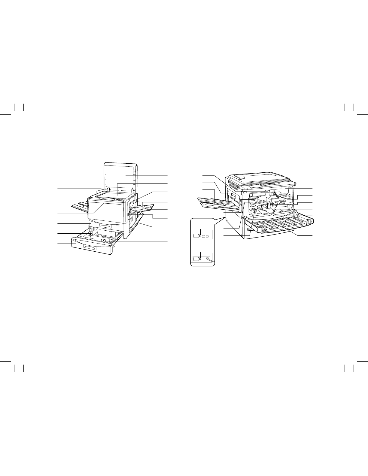
1-3-1 Machine parts names and their functions
(1) Main body
Figure 1-3-1 Machine parts names and their functions
1 Front cover
2 Original cover
3 Operation panel
4 Paper transfer section release lever
5 Fixing unit handle
6 Fixing unit
7 Fixing unit anchor screw
8 Fixing unit knob
9 Total counter
0 Toner cartridge
! Drawer 1
@ Drawer 2
# Width adjustment lever
$ Length adjustment lever
% Stack bypass tray
^ Support guide
& Insert guides
* Right cover
( Ejection cover
) Copy tray
⁄ Main power switch
¤ Original size indicator lines
‹ Platen
› Main charger cleaning knob
fi Transfer charger cleaning knob
fl Dehumidifying heater switch
¤
3
!
$
@
2
‹
&
%
^
⁄
*
#
7
6
8
9
(
)
0
›
fi
4
5
1
fl
Metric
fl
Inch
A
AA A
A
A
AA A
A
E
EE E
E
E
EE E
E
1AH (1-3-1E)
1AH
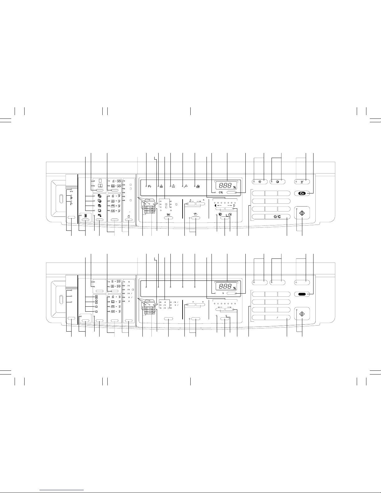
Figure 1-3-2 Operation panel
(2) Operation panel
Inch
Metric
123
789
Interrupt
Auto
Selection
Energy
Saver
Print
Reset
Staple
Sort
Group
RADF
2 Sided Original
2 Page Original
RADF
Duplex
Duplex
Duplex
Duplex
2 Page Original
Odd 1 Sided
Originals
Even 1 Sided
Originals
#
#
Non-Copy
Non-Copy
Non-Copy
Copy
Copy
Non-Copy
Presentation
F
R
F
F
F
R
Border Erase
Book Erase
Margin
2 Sided Original
8
1
2
14
8
1
2
11
R
8
1
2
11
1711
1511
5
1
2
8
1
2
Misfeed
Add
Paper
Add
Toner
Maintenance
Check
Paper Size/
Direction
Recall
U
Auto
Exposure
Manual
Photo
Original
Dark Light
Zoom( )
Zoom( )
1234567
Paper
Select
8
1
2
14
8
1
2
11
R
8
1
2
11
1711 5
1
2
8
1
2
Page
Separation
Page
Separation
Original
456
0
Stop Clear
´ ¤ ( %⁄
Œ
· ‡ fl fi › ‹ 0 8 9 3 2 1 4
567!$&*)¤°
¤‰
^
#@
‚„ˇÁ
123
789
Reset
#
#
1234567
456
0
50
200
A
4
B4A
3
Folio
B
5
R
A
4
R
A
5
R
U
A
4
B
4
A
3
B
5
B
5
R
A
4
R
A
5
R
1511
Folio
RADF
RADF
2.4.6
…
3.5.7
…
´ ¤ ( %⁄
Œ
· ‡ fl fi › ‹ 0 8 9 3 2 1 4
567!$&*)¤°
¤‰
^
#@
‚„ˇÁ
1-3-2

1AH
1-3-3
Metric
1 Interrupt key/Interrupt indicator
2 Preheat key/Preheat indicator
3 Auto selection key/Auto selection
indicator
4 All clear key
5 Print key/Print indicator
6 Stop/clear key
7 Numeric keys
8 Copy number/zoom ratio indicator
9 Zoom call key
0 Zoom indicator
! Exposure select key
@ Auto exposure indicator
# Photo original indicator
$ Exposure adjustment keys
% Exposure scale
^ Zoom keys
& Manual key/Manual indicator
* Paper select key
( Paper select indicators
) Drawer selection indicators
⁄ Stack bypass selection indicator
¤ Jam location indicators
‹ Check paper size/direction indicator
› Maintenance indicator
fi Add toner indicator
fl Add paper indicator
‡ Jam indicator
° Original key/Original size indicators
· Page separation key/Page
separation indicators
‚ Duplex key/Duplex indicators
ΠBorder erase key/Border erase
indicators
„ Presentation/cover key
´ Cover indicators
‰ Presentation indicator
ˇ Margin key/Margin indicator
Á Sorter mode selection key/Sorter
mode indicators
Inch
1 Interrupt key/Interrupt indicator
2 Energy saver key/Energy saver
indicator
3 Auto selection key/Auto selection
indicator
4 Reset key
5 Print key/Print indicator
6 Stop/clear key
7 Numeric keys
8 Copy number/zoom ratio indicator
9 Zoom call key
0 Zoom indicator
! Exposure select key
@ Auto exposure indicator
# Photo original indicator
$ Exposure adjustment keys
% Exposure scale
^ Zoom keys
& Manual key/Manual indicator
* Paper select key
( Paper select indicators
) Drawer selection indicators
⁄ Stack bypass selection indicator
¤ Misfeed location indicators
‹ Check paper size/direction indicator
› Maintenance indicator
fi Add toner indicator
fl Add paper indicator
‡ Misfeed indicator
° Original key/Original size indicators
· Page separation key/Page
separation indicators
‚ Duplex key/Duplex indicators
ΠBorder erase key/Border erase
indicators
„ Presentation/cover key
´ Cover indicators
‰ Presentation indicator
ˇ Margin key/Margin indicator
Á Sorter mode selection key/Sorter
mode indicators
1AH
1-3-4
3
5
5
1
6
2
4
Light path
Paper path
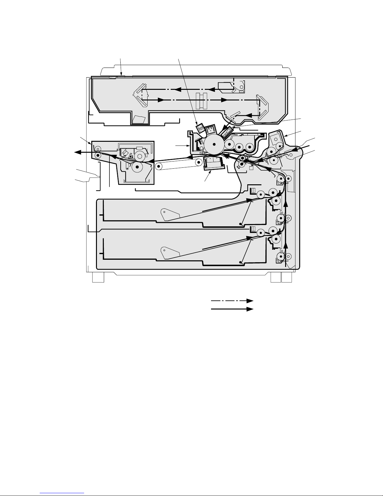
1-3-2 Machine cross sections
1 Paper feed section (page 1-3-10)
2 Image formation section (page 1-3-18)
• Main charging section (page 1-3-19)
• Developing section (page 1-3-23)
• Cleaning section (page 1-3-30)
3 Exposure section (page 1-3-31)
4 Transfer and separation sections
(page 1-3-38)
5 Charge erasing section (page 1-3-41)
6 Fixing and eject sections (page 1-3-44)
Figure 1-3-3 Machine cross section – copier

1AH
1-3-5
1 Feedshift section (page 1-3-48)
2 Duplex section (page 1-3-49)
Figure 1-3-4 Machine cross section – feedshift and duplex sections (optional)
Figure 1-3-5 Machine cross section – special tray (optional)
1
2
Paper path
Special tray (page 1-3-56)
Paper path
1AH
1-3-6
1
¯
23 4 5
6
7
∏
Å
Í
Î
Ï
˝
Ø
ˆ
¨
Á
ˇ
‰
˘
¿
£
¢
¡
™
∞
´
„
Œ
‚
·
°
‡
fl
fi
Ô
8
9
0
@
#
%
$
&
*
(
)
‹
º
œ
∑
®
¤
›
¶
•
§
ª
†
⁄
^
!
Ò
ı
˜
Â
˛
Ú
¸
Ç
◊
Ó
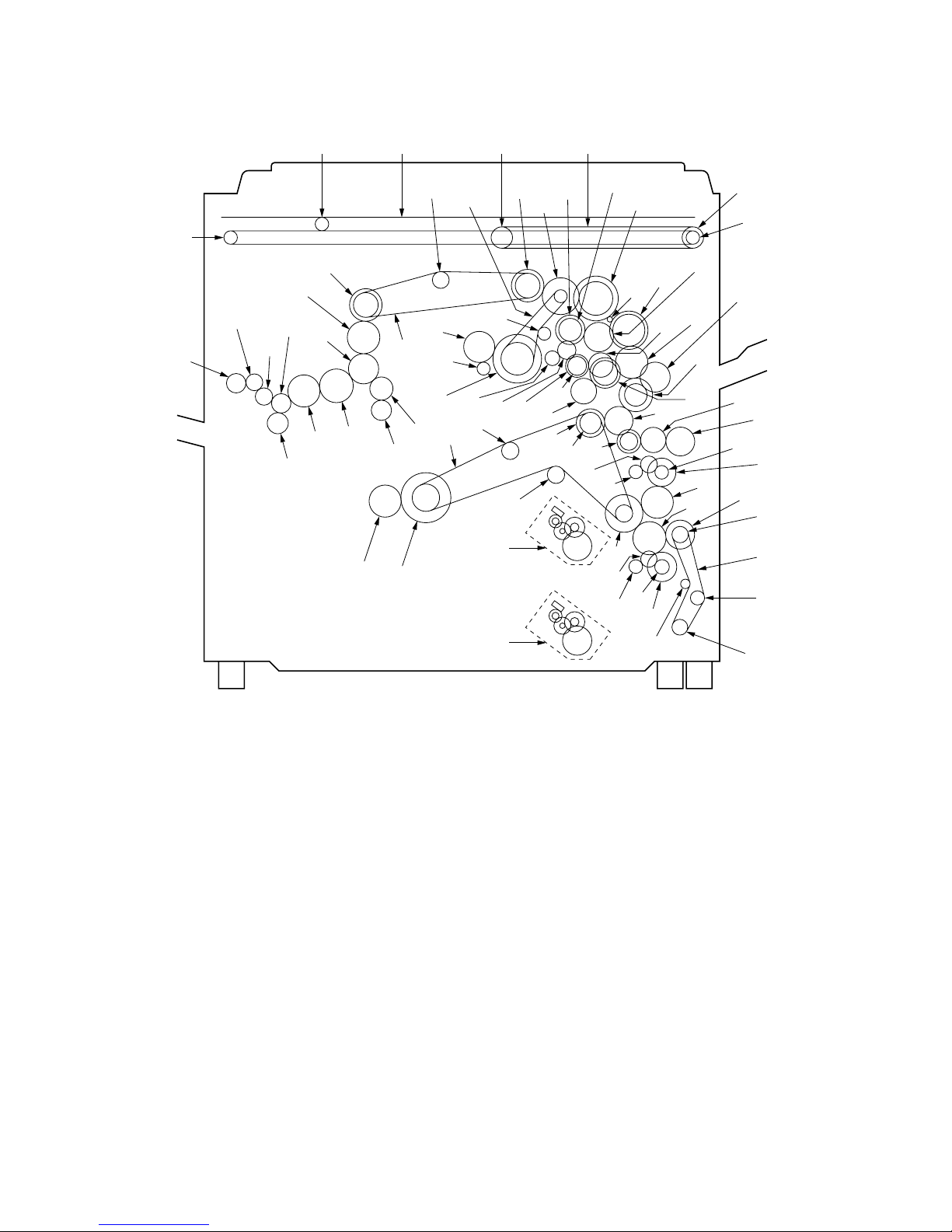
1-3-3 Drive system
Figure 1-3-6 Drive system – copier
 Loading...