

Page 1

CS-3050
CS-4050
CS-5050
SERVICE
MANUAL
Published in May 08
2GN70949
Revision 9
Page 2

CAUTION
RISK OF EXPLOSION IF BATTERY IS REPLACED BY AN INCORRECT TYPE. DISPOSE OF
USED BATTERIES ACCORDING TO THE INSTRUCTIONS.
It may be illegal to dispose of this battery into the municipal waste stream. Check with your local
solid waste officials for details in your area for proper disposal.
ATTENTION
IL Y A UN RISQUE D’EXPLOSION SI LA BATTERIE EST REMPLACEE PAR UN MODELE DE
TYPE INCORRECT. METTRE AU REBUT LES BATTERIES UTILISEES SELON LES INSTRUCTIONS DONNEES.
Il peut être illégal de jeter les batteries dans des eaux d’égout municipales. Vérifiez avec les fonctionnaires municipaux de votre région pour les détails concernant des déchets solides et une mise
au rebut appropriée.
Page 3

Revision history
Revision Date Replaced pages Remarks
1 November 10, 2006 CONTENTS, 1-1-1 to 1-1-3, 1-1-5, 1-2-2, 1-2-4 to 6,
1-2-9 to 1-2-12, 1-3-5 to 1-3-102, 1-4-1, 1-4-2, 1-4-6,
1-4-7, 1-4-22, 1-4-25, 1-4-28, 1-4-31, 1-4-32,
1-4-35 to 37, 1-4-57 to 60, 1-5-4 to 8, 1-5-16, 1-5-19,
1-5-23, 1-5-25 to 1-5-40, 1-6-1 to 1-6-4, 2-1-1, 2-1-4,
2-1-10, 2-1-13, 2-1-15, 2-2-4, 2-2-6, 2-3-1, 2-3-2,
2-3-8, 2-3-11, 2-3-13 to 2-3-16, 2-4-1 to 2-4-6
-
2 January 26, 2007 CONTENTS, 1-1-2, 1-1-5, 1-2-3, 1-2-4, 1-2-11,
1-3-5, 1-3-6, 1-3-8, 1-3-9, 1-3-11 to 1-3-14, 1-3-16 to
1-3-19, 1-3-24, 1-3-32, 1-3-49, 1-3-50, 1-3-52 to
1-3-55, 1-3-60, 1-3-65, 1-3-67, 1-3-72 to 1-3-77,
1-3-82 to 1-3-102, 1-4-6, 1-4-9, 1-4-12, 1-4-14,
1-4-15, 1-4-20, 1-4-24, 1-4-40, 1-4-41, 1-4-51,
1-5-13, 1-5-22, 1-5-40, 2-2-1, 2-2-4, 2-3-10, 2-3-12,
2-3-16, 2-4-9
3 March 2, 2007 CONTENTS, 1-1-2 to 1-1-4, 1-3-3, 1-3-6, 1-3-41,
1-3-63, 1-3-71, 1-3-85, 1-4-22, 1-4-32, 1-4-43,
2-4-1, 2-4-2
4 March 16, 2007 1-3-76 -
5 May 7, 2007 1-3-2, 1-3-5, 1-3-21 to 1-3-23, 1-3-36, 1-3-68,
1-3-70, 1-3-71, 1-3-73, 1-3-74, 1-3-83, 1-4-5,
1-4-15, 1-4-17 to 1-4-21, 1-5-20
6 August 31, 2007 CONTENTS, 1-2-1, 1-2-11, 1-2-12, 1-3-7, 1-3-21,
1-3-24, 1-3-25, 1-3-35, 1-3-36, 1-3-39, 1-3-51,
1-3-63, 1-3-68 to 1-3-70, 1-3-85, 1-4-1, 1-4-15,
1-4-22 to 1-4-24, 1-4-43, 1-5-23, 2-3-5
7 November 30, 2007 CONTENTS, 1-1-1 to 1-1-3, 1-2-4, 1-3-3 to 1-3-6,
1-3-8 to 1-3-10, 1-3-48 to 1-3-50, 1-3-76, 1-3-77,
1-3-81 to 1-3-105, 1-6-1, 2-4-1, 2-4-2
8 April 1, 2008 CONTENTS, 1-1-2, 1-2-13, 1-5-2 -
-
-
-
-
-
9 April 25, 2008 1-5-25 -
Page 4

This page is intentionally left blank.
Page 5

Safety precautions
This booklet provides safety warnings and precautions for our service personnel to ensure the safety of
their customers, their machines as well as themselves during maintenance activities. Service personnel
are advised to read this booklet carefully to familiarize themselves with the warnings and precautions
described here before engaging in maintenance activities.
Page 6
Safety warnings and precautions
Various symbols are used to protect our service personnel and customers from physical danger and
to prevent damage to their property. These symbols are described below:
DANGER: High risk of serious bodily injury or death may result from insufficient attention to or incorrect
compliance with warning messages using this symbol.
WARNING: Serious bodily injury or death may result from insufficient attention to or incorrect compliance
with warning messages using this symbol.
CAUTION: Bodily injury or damage to property may result from insufficient attention to or incorrect
compliance with warning messages using this symbol.
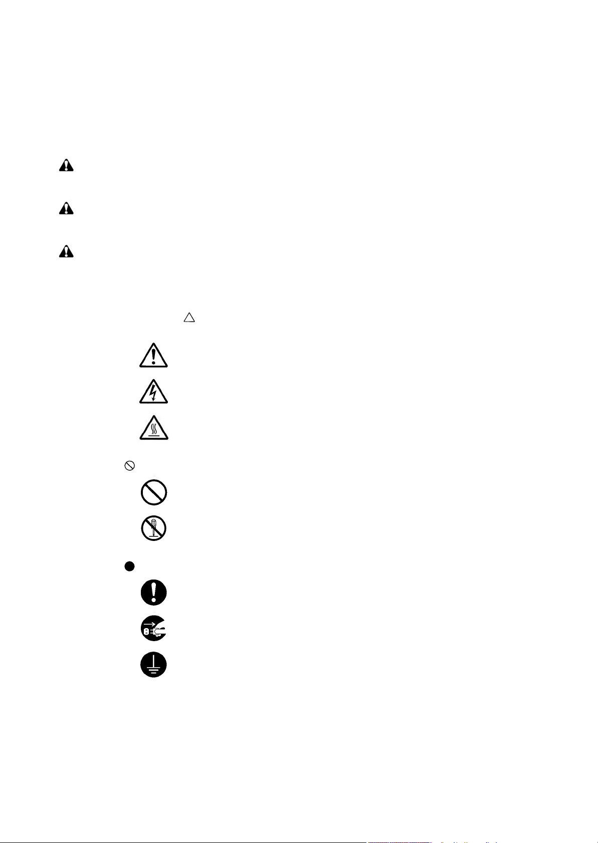
Symbols
The triangle ( ) symbol indicates a warning including danger and caution. The specific point
of attention is shown inside the symbol.
General warning.
Warning of risk of electric shock.
Warning of high temperature.
indicates a prohibited action. The specific prohibition is shown inside the symbol.
General prohibited action.
Disassembly prohibited.
indicates that action is required. The specific action required is shown inside the symbol.
General action required.
Remove the power plug from the wall outlet.
Always ground the copier.
Page 7
1.Installation Precautions
WARNING
• Do not use a power supply with a voltage other than that specified. Avoid multiple connections to
one outlet: they may cause fire or electric shock. When using an extension cable, always check
that it is adequate for the rated current. .............................................................................................
• Connect the ground wire to a suitable grounding point. Not grounding the copier may cause fire or
electric shock. Connecting the earth wire to an object not approved for the purpose may cause
explosion or electric shock. Never connect the ground cable to any of the following: gas pipes,
lightning rods, ground cables for telephone lines and water pipes or faucets not approved by the
proper authorities. ............................................................................................................................
CAUTION:
• Do not place the copier on an infirm or angled surface: the copier may tip over, causing injury. .......
• Do not install the copier in a humid or dusty place. This may cause fire or electric shock. ................
• Do not install the copier near a radiator, heater, other heat source or near flammable material.
This may cause fire. .........................................................................................................................
• Allow sufficient space around the copier to allow the ventilation grills to keep the machine as cool
as possible. Insufficient ventilation may cause heat buildup and poor copying performance. ...........
• Always handle the machine by the correct locations when moving it. ...............................................
• Always use anti-toppling and locking devices on copiers so equipped. Failure to do this may cause
the copier to move unexpectedly or topple, leading to injury. ...........................................................
• Avoid inhaling toner or developer excessively. Protect the eyes. If toner or developer is accidentally ingested, drink a lot of water to dilute it in the stomach and obtain medical attention immediately. If it gets into the eyes, rinse immediately with copious amounts of water and obtain medical
attention. ......................................................................................................................................
• Advice customers that they must always follow the safety warnings and precautions in the copier’s
instruction handbook. .....................................................................................................................
Page 8
2.Precautions for Maintenance
WARNING
• Always remove the power plug from the wall outlet before starting machine disassembly. ...............
• Always follow the procedures for maintenance described in the service manual and other related
brochures. .......................................................................................................................................
• Under no circumstances attempt to bypass or disable safety features including safety mechanisms
and protective circuits. .....................................................................................................................
• Always use parts having the correct specifications. ..........................................................................
• Always use the thermostat or thermal fuse specified in the service manual or other related brochure when replacing them. Using a piece of wire, for example, could lead to fire or other serious
accident. ..........................................................................................................................................
• When the service manual or other serious brochure specifies a distance or gap for installation of a
part, always use the correct scale and measure carefully. ................................................................
• Always check that the copier is correctly connected to an outlet with a ground connection. .............
• Check that the power cable covering is free of damage. Check that the power plug is dust-free. If it
is dirty, clean it to remove the risk of fire or electric shock. ..............................................................
• Never attempt to disassemble the optical unit in machines using lasers. Leaking laser light may
damage eyesight. ...........................................................................................................................
• Handle the charger sections with care. They are charged to high potentials and may cause electric
shock if handled improperly. ............................................................................................................
CAUTION
• Wear safe clothing. If wearing loose clothing or accessories such as ties, make sure they are
safely secured so they will not be caught in rotating sections. ..........................................................
• Use utmost caution when working on a powered machine. Keep away from chains and belts. ........
• Handle the fixing section with care to avoid burns as it can be extremely hot. ..................................
• Check that the fixing unit thermistor, heat and press rollers are clean. Dirt on them can cause
abnormally high temperatures. ........................................................................................................
Page 9
• Do not remove the ozone filter, if any, from the copier except for routine replacement. ....................
• Do not pull on the AC power cord or connector wires on high-voltage components when removing
them; always hold the plug itself. .....................................................................................................
• Do not route the power cable where it may be stood on or trapped. If necessary, protect it with a
cable cover or other appropriate item. .............................................................................................
• Treat the ends of the wire carefully when installing a new charger wire to avoid electric leaks. ........
• Remove toner completely from electronic components. ...................................................................
• Run wire harnesses carefully so that wires will not be trapped or damaged. ....................................
• After maintenance, always check that all the parts, screws, connectors and wires that were
removed, have been refitted correctly. Special attention should be paid to any forgotten connector,
trapped wire and missing screws. ...................................................................................................
• Check that all the caution labels that should be present on the machine according to the instruction
handbook are clean and not peeling. Replace with new ones if necessary. ......................................
• Handle greases and solvents with care by following the instructions below: .....................................
· Use only a small amount of solvent at a time, being careful not to spill. Wipe spills off completely.
· Ventilate the room well while using grease or solvents.
· Allow applied solvents to evaporate completely before refitting the covers or turning the power
switch on.
· Always wash hands afterwards.
• Never dispose of toner or toner bottles in fire. Toner may cause sparks when exposed directly to
fire in a furnace, etc. .......................................................................................................................
• Should smoke be seen coming from the copier, remove the power plug from the wall outlet imme-
diately. ............................................................................................................................................
3.Miscellaneous
WARNING
• Never attempt to heat the drum or expose it to any organic solvents such as alcohol, other than the
specified refiner; it may generate toxic gas. .....................................................................................
Page 10

This page is intentionally left blank.
Page 11

2GN/2GP/2GR-8
CONTENTS
1-1 Specifications
1-1-1 Specifications..........................................................................................................................................1-1-1
1-1-2 Parts names............................................................................................................................................1-1-4
(1) Machine.............................................................................................................................................1-1-4
(2) Operation panel.................................................................................................................................1-1-5
1-1-3 Machine cross section ............................................................................................................................1-1-6
1-2 Installation
1-2-1 Installation environment.........................................................................................................................1-2-1
1-2-2 Unpacking and installation......................................................................................................................1-2-2
(1) Installation procedure ........................................................................................................................1-2-2
(2) Setting initial copy modes................................................................................................................1-2-10
1-2-3 Installing the key counter (option) .........................................................................................................1-2-11
1-2-4 Installing the expanded memory (option)..............................................................................................1-2-13
1-3 Maintenance Mode
1-3-1 Maintenance mode .................................................................................................................................1-3-1
(1) Executing a maintenance item ..........................................................................................................1-3-1
(2) Maintenance modes item list.............................................................................................................1-3-2
(3) Contents of the maintenance mode items.........................................................................................1-3-6
1-3-2 User management ................................................................................................................................1-3-90
(1) Using the user management mode .................................................................................................1-3-90
(2) Common settings ............................................................................................................................1-3-91
(3) Copy settings...................................................................................................................................1-3-95
(4) Sending settings..............................................................................................................................1-3-96
(5) Document box/Removable memory settings...................................................................................1-3-96
(6) Printer settings ................................................................................................................................1-3-97
(7) Network setup .................................................................................................................................1-3-99
(8) Printing reports/Sending notice .......................................................................................................1-3-99
(9) Adjustment/Maintenance...............................................................................................................1-3-100
(10) Date/Timer.....................................................................................................................................1-3-101
(11) Editing Destination (Address Book/Adding One-Touch Keys) ......................................................1-3-102
(12) Restarting the system/Connecting the PC ....................................................................................1-3-103
(13) User login administration...............................................................................................................1-3-103
(14) Job accounting ..............................................................................................................................1-3-104
1-4 Troubleshooting
1-4-1 Paper misfeed detection .........................................................................................................................1-4-1
(1) Paper misfeed indication ...................................................................................................................1-4-1
(2) Paper misfeed detection conditions ..................................................................................................1-4-2
(3) Paper misfeeds ...............................................................................................................................1-4-11
1-4-2 Self-diagnosis .......................................................................................................................................1-4-22
(1) Self-diagnostic function ...................................................................................................................1-4-22
(2) Self diagnostic codes ......................................................................................................................1-4-23
1-4-3 Image formation problems ....................................................................................................................1-4-44
(1) No image appears (entirely white)...................................................................................................1-4-45
(2) No image appears (entirely black)...................................................................................................1-4-45
(3) Image is too light. ............................................................................................................................1-4-46
(4) Background is visible.......................................................................................................................1-4-46
(5) A white line appears longitudinally. .................................................................................................1-4-46
(6) A black line appears longitudinally. .................................................................................................1-4-47
(7) A black line appears laterally...........................................................................................................1-4-47
(8) One side of the copy image is darker than the other.......................................................................1-4-47
(9) Black dots appear on the image......................................................................................................1-4-47
(10) Image is blurred...............................................................................................................................1-4-48
(11) The leading edge of the image is consistently misaligned with the original. ...................................1-4-48
(12) The leading edge of the image is sporadically misaligned with the original....................................1-4-48
(13) Paper creases. ................................................................................................................................1-4-48
(14) Offset occurs. ..................................................................................................................................1-4-49
Page 12

2GN/2GP/2GR-8
(15) Image is partly missing....................................................................................................................1-4-49
(16) Fusing is poor..................................................................................................................................1-4-49
(17) Image is out of focus. ......................................................................................................................1-4-49
(18) Image center does not align with the original center.......................................................................1-4-50
(19) Image is not square.........................................................................................................................1-4-50
1-4-4 Electric problems ..................................................................................................................................1-4-51
1-4-5 Mechanical problems............................................................................................................................1-4-55
1-4-6 Send error code ....................................................................................................................................1-4-57
(1) Scan to SMB error codes ................................................................................................................1-4-57
(2) Scan to FTP error codes .................................................................................................................1-4-58
(3) Scan to E-mail error codes..............................................................................................................1-4-59
(4) Network Twain error codes .............................................................................................................1-4-60
(5) Software trouble error codes...........................................................................................................1-4-60
1-5 Assembly and Disassembly
1-5-1 Precautions for assembly and disassembly............................................................................................1-5-1
(1) Precautions .......................................................................................................................................1-5-1
(2) Drum..................................................................................................................................................1-5-1
(3) Toner .................................................................................................................................................1-5-1
(4) How to tell a genuine Kyocera Mita toner container ..........................................................................1-5-2
1-5-2 Paper feed section..................................................................................................................................1-5-3
(1) Detaching and refitting the forwarding, paper feed and separation pulleys ......................................1-5-3
(2) Detaching and refitting the MP separation, MP paper feed and MP forwarding pulleys ...................1-5-5
(3) Detaching and refitting the left and right registration cleaner ..........................................................1-5-10
1-5-3 Optical section ......................................................................................................................................1-5-12
(1) Detaching and refitting the exposure lamp......................................................................................1-5-12
(2) Detaching and refitting the scanner wires .......................................................................................1-5-14
(3) Detaching and refitting the ISU (reference).....................................................................................1-5-19
(4) Adjusting the position of the ISU (reference)...................................................................................1-5-21
(5) Detaching and refitting the laser scanner unit.................................................................................1-5-22
(6) Adjusting the skew of the laser scanner unit (reference) ................................................................1-5-24
1-5-4 Drum section.........................................................................................................................................1-5-25
(1) Detaching and refitting the drum unit ..............................................................................................1-5-25
(2) Detaching and refitting the main charger unit..................................................................................1-5-26
(3) Detaching and refitting the drum separation claws .........................................................................1-5-27
1-5-5 Developing section................................................................................................................................1-5-28
(1) Detaching and refitting the developing unit .....................................................................................1-5-28
1-5-6 Transfer section ....................................................................................................................................1-5-29
(1) Detaching and refitting the transfer roller unit .................................................................................1-5-29
1-5-7 Fuser section ........................................................................................................................................1-5-30
(1) Detaching and refitting the fuser unit...............................................................................................1-5-30
(2) Detaching and refitting the heat roller separation claws..................................................................1-5-31
(3) Detaching and refitting the press roller............................................................................................1-5-32
(4) Detaching and refitting the fuser heater ..........................................................................................1-5-33
(5) Detaching and refitting the heat roller .............................................................................................1-5-34
(6) Detaching and refitting the fuser unit thermistor 1 and 2.................................................................1-5-35
(7) Adjusting front position of the fuser unit (adjusting lateral squareness)..........................................1-5-36
1-5-8 Others .....................................................................................................................
(1) Detaching and refitting the ozone filter 1 and 2...............................................................................1-5-37
(2) Detaching and refitting the dust filter 1 and 2..................................................................................1-5-38
(3) Detaching and refitting the hard disk...............................................................................................1-5-39
..............................1-5-37
1-6 Requirements on PWB Replacement
1-6-1 Upgrading the firmware...........................................................................................................................1-6-1
1-6-2 Adjustment-free variable resistors (VR) ..................................................................................................1-6-1
1-6-3 Remarks on main PWB replacement......................................................................................................1-6-2
1-6-4 Remarks on engine PWB replacement...................................................................................................1-6-2
1-6-5 Remarks on scanner PWB replacement.................................................................................................1-6-3
Page 13

2GN/2GP/2GR-8
2-1 Mechanical construction
2-1-1 Paper feed section..................................................................................................................................2-1-1
2-1-2 Main charging section.............................................................................................................................2-1-4
2-1-3 Optical section ........................................................................................................................................2-1-5
(1) Original scanning...............................................................................................................................2-1-6
(2) Image printing....................................................................................................................................2-1-7
2-1-4 Developing section................................................................................................................................2-1-10
(1) Single component developing system.............................................................................................2-1-12
2-1-5 Transfer and separation sections..........................................................................................................2-1-13
2-1-6 Cleaning and charge erasing sections..................................................................................................2-1-14
2-1-7 Fuser section ........................................................................................................................................2-1-15
2-1-8 Eject and switchback sections ..............................................................................................................2-1-16
2-1-9 Duplex section ......................................................................................................................................2-1-17
(1) Paper conveying operation in duplex copying.................................................................................2-1-18
2-2 Electrical Parts Layout
2-2-1 Electrical parts layout..............................................................................................................................2-2-1
(1) PWBs ................................................................................................................................................2-2-1
(2) Switches and sensors .......................................................................................................................2-2-2
(3) Motors ...............................................................................................................................................2-2-4
(4) Other electrical components..............................................................................................................2-2-5
2-3 Operation of the PWBs
2-3-1 Power source PWB.................................................................................................................................2-3-1
2-3-2 Engine PWB............................................................................................................................................2-3-5
2-3-3 Main operation unit PWB ......................................................................................................................2-3-13
2-4 Appendixes
Maintenance parts list.............................................................................................................................2-4-1
Maintenance kits.....................................................................................................................................2-4-2
Periodic maintenance procedures ..........................................................................................................2-4-3
Chart of image adjustment procedures...................................................................................................2-4-7
General wiring diagram...........................................................................................................................2-4-9
INSTALLATION GUIDE
DOCUMENT PROCESSOR
PAPER FEEDER
3000 SHEETS PAPER FEEDER
DOCUMENT FINISHER
3000 SHEETS DOCUMENT FINISHER
CENTER-FOLDING UNIT
MAILBOX
HOLE PUNCH UNIT
BUILT-IN FINISHER
JOB SEPARATOR
FAX System (M)
Data Security Kit (C)
UG-30
Page 14

2GN/2GP/2GR-1
This page is intentionally left blank.
Page 15

2GN/2GP/2GR-7
1-1 Specifications
1-1-1 Specifications
Type................................................Desktop
Copying method..............................Indirect electrostatic system
Supported original types ................. Sheets, books and three-dimensional objects
Maximum original size: A3/Ledger
Original feed system.......................Fixed
Paper weight...................................Cassette: 60 - 105 g/m
MP tray : 45 - 200 g/m
Paper type ......................................Cassette: Plain, Preprinted, Bond, Recycled, Rough, Letterhead, Color, Prepunched,
High quality and Custom1 - 8
MP tray :Plain, Transparency, Preprinted, Labels, Bond, Recycled, Vellum, Rough,
Letterhead, Color, Prepunched, Envelope, Cardstock, Thick paper,
High quality and Custom1 - 8
Paper size.......................................Cassette: Ledger, Legal, Oficio II, 8.5 x 13.5", Letter, LetterR, StatementR, A3, B4,
A4, A4R, B5, B5R, A5R, Folio, 8K, 16K, 16KR
MP tray :Ledger, Legal, Oficio II, 8.5 x 13.5", Letter, LetterR, Executive, StatementR,
A3, B4, A4, A4R, B5, B5(ISO), B5R, A5R, B6R, A6R, Oufuku Hagaki,
Hagaki, Envelope DL, Envelope C5, Envelope C4, Comm.#10, Comm.#9,
Comm.#6-3/4, Monarch, Youkei 2, Youkei 4, Folio, 8K, 16K, 16KR
Zoom level ......................................Manual mode: 25 - 400%, 1% increment
Auto copy mode: fixed ratios
Metric
± 1.0%, 1:4.00/1:2.00/1:1.41/1:1.22/1:1.15/1:0.86/1:0.81/1:0.70/1:0.50/1:0.25
1:1
Inch
1:1
± 1.0%, 1:4.00/1:2.00/1:1.29/1:1.21/1:0.78/1:0.64/1:0.50/1:0.25
Copying speed................................At 100% magnification in copy mode:
[30 ppm model]
A3/Ledger: 20 sheets/min.
B4/Legal: 20 sheets/min.
A4/Letter: 30 sheets/min.
A4R/LetterR: 22 sheets/min.
B5: 30 sheets/min.
B5R: 20 sheets/min.
A5R: 14 sheets/min.
A6R: 16 sheets/min.
[40 ppm model]
A3/Ledger: 23 sheets/min.
B4/Legal: 23 sheets/min.
A4/Letter: 40 sheets/min.
A4R/LetterR: 27 sheets/min.
B5: 40 sheets/min.
B5R: 22 sheets/min.
A5R: 16 sheets/min.
A6R: 18 sheets/min.
[50 ppm model]
A3/Ledger: 26 sheets/min.
B4/Legal: 26 sheets/min.
A4/Letter: 50 sheets/min.
A4R/LetterR: 31 sheets/min.
B5: 50 sheets/min.
B5R: 24 sheets/min.
A5R: 18 sheets/min.
A6R: 18 sheets/min.
First copy time ................................3.9 s or less (30 ppm model)
3.5 s or less (40/50 ppm model)
Warm-up time .................................30 s (room temperature 22
Recovery from sleep mode: 15 s (room temperature 22°C/71.6°F, 60% RH)
Paper capacity ................................Cassette: 500 sheets (80 g/m2)
MP tray :200 sheets (80 g/m2)
Output tray capacity........................Top tray : 250 sheets (80 g/m
150 sheets (80 g/m2, with built-in finisher)
2
2
°C/71.6°F, 60% RH)
2
)
1-1-1
Page 16

2GN/2GP/2GR-8
Continuous copying ........................1 to 999 sheets
Light source ....................................Inert gas lamp
Scanning system ............................Flat bed scanning by CCD image sensor
Photoconductor...............................a-Si (drum diameter 40 mm)
Image write system.........................Semiconductor laser
Charging system.............................Single positive corona charging
Developing system .........................Dry, reverse developing (single component system)
Developer: 1-component, magnetism toner
Toner replenishing: automatic from a toner container
Transfer system ..............................Transfer roller
Separation system..........................Separation electrode
Cleaning system .............................Cleaning blade and roller
Charge erasing system...................Exposure by cleaning lamp
Fusing system.................................Heat roller
Heat source: halogen heaters
Abnormally high temperature protection devices: thermostats
Memory...........................................Standard 512 MB/Maximum 1024 MB
Hard disk.........................................80 GB
Resolution.......................................Scanning: 600 x 600 dpi
Printing : 600 x 600 dpi (photo mode: 1800 dpi equivalent x 600 dpi)
Operating environment ................... Temperature: 10 to 32.5
°C/50 to 90.5°F
Humidity: 15 to 80% RH
Altitude: 2500 m/8,202 ft maximum
Brightness: 1500 lux maximum
Dimensions .....................................599 (W) x 646 (D) x 745 (H) mm
9/16" (W) x 25 7/16" (D) x 29 5/16" (H)
23
Weight.............................................Approx. 85 kg/187 lbs
Space required................................753 (W) x 646 (D) mm
5/8" (W) x 25 7/16" (D)
29
Functions ........................................Original size, Paper selection, Mixed sized originals, Original orientation, Collate/Off-
set mode, Staple/Punch mode, Output destination, Zoom mode, Combine mode, Mar-
gin/Centering mode, Border erase, Booklet from sheets, Duplex, Cover mode, Form
overlay, Page numbering, Memo mode, Density adjustment, Selection of image qual-
ity, EcoPrint mode, Batch scanning, Auto image rotation, Inverted copying, Mirror
image, Job finish notice, File name, Priority override, Multi-page forms, Repeat copy,
Programmed copying, Registering shortcuts
Power source..................................120 V AC, 60 Hz, 11.5 A
220 to 240 V AC, 50 Hz, 6.3 A
Options ...........................................Document processor, paper feeder, 3000-sheet paper feeder, document finisher,
3000-sheet document finisher, centerfold unit, mailbox, punch unit, built-in finisher,
job separator, key counter, fax kit, security kit, fax backup kit, serial interface,
upgrade kit and expanded memory
1-1-2
Page 17

2GN/2GP/2GR-7
Printer functions
Printing speed.................................Same as copying speed
First print time.................................Same as first copy time
Resolution.......................................300 dpi/600 dpi/Fast 1200 mode
Supported OS .................................Microsoft Windows 95 (OSR2)
Microsoft Windows 98 (second edition)
Microsoft Windows NT4.0 (service pack 5 or later)
Microsoft Windows 2000 (service pack 2 or later)
Microsoft Windows Me
Microsoft Windows XP
Microsoft Windows Server 2003
Apple Macintosh OS 9.x
Apple Macintosh OS X 10.x
Interface..........................................Parallel interface: 1 (based on IEEE1284)
Network interface: 1
USB memory slot: 3 (USB Hi-speed)
USB interface connector: 1 (USB Hi-speed)
Optional serial interface: 1 (RS-232C)
PDL.................................................PRESCRIBE
Emulation........................................PCL6 (5e, XL), KPDL3, KC-GL, Line Printer, IBM Proprinter X24E, EPSON LQ-850,
DIABLO 630
Font.................................................Outline font: 80 fonts (PCL6)/136 fonts (KPDL3)
Bitmap font: 1 font/79 fonts are processed by outline font.
Connectivity ....................................Plug & Play
SNMP (printer MIB supported)
Scanner functions
Ethernet ..........................................10BASE-T/100BASE-TX
Network protocol.............................TCP/IP
Transmission system ...................... PC transmission: SMB Scan to SMB, FTP Scan to FTP
E-mail transmission: SMTP Scan to E-mail
TWAIN scan: TWAIN source
Resolution.......................................600 dpi, 400 dpi, 300 dpi, 200 dpi, 200 x 100 dpi, 200 x 400 dpi
Gradation........................................B/W : (a) Text mode: Binary/dot 256 gradations (error diffusion)
(b) Photo mode: Binary/dot 256 gradations (error diffusion)
(c) Text/Photo mode: Binary/dot 256 gradations (error diffusion)
(d) OCR mode: Binary/dot 2 gradations
Color: RGB 256 values/dot
Scanning capacity........................... Max. 999 sheets (998 sheets for 2-sided originals)
File format.......................................Monochrome: PDF (MMR), TIFF (MMR)
Gray: PDF (JPEG), TIFF (JPEG), JPEG
Color: PDF (JPEG), TIFF (JPEG), JPEG, PDF (high compression)
Scanning speed..............................1-sided: monochrome 50 sheets/min, Color 25 sheets/min
2-sided: monochrome 25 sheets/min, Color 12.5 sheets/min
NOTE: These specifications are subject to change without notice.
1-1-3
Page 18
2GN/2GP/2GR-3
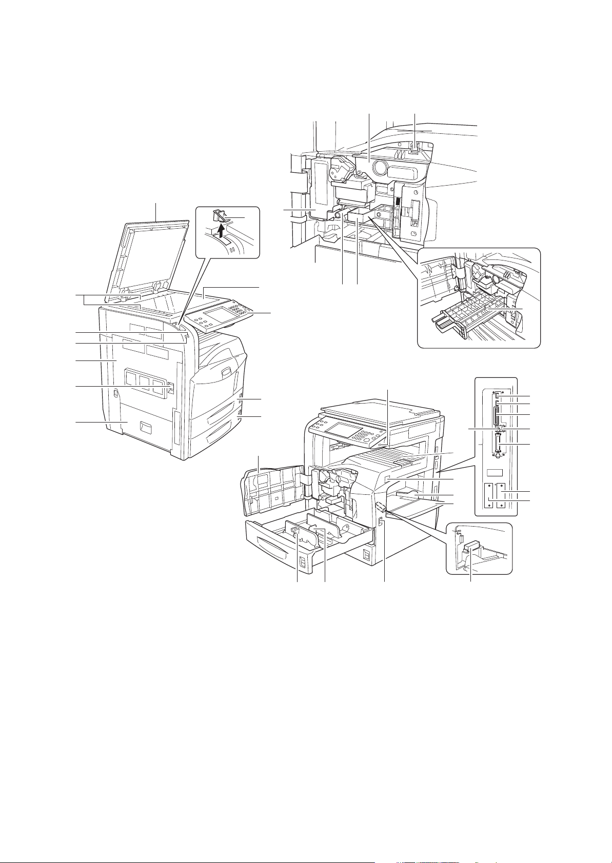
1-1-2 Parts names
(1) Machine
1413
1
15
3
2
4
5
6
7
8
9
10
11
12
20
16 17
19
23
24
25
26
32
18
29
30
31
33
34
35
36
1. Original cover (Option)
2. Original size indicator plates
3. Clip holder
4. Reception indicator
5. Error indicator
6. Left cover 1
7. Left cover 1 Lever
8. Left cover 2
9. Platen
10. Operation panel
11. Ca sse tte 1
12. Cassette 2
1-1-4
21 22
Figure 1-1-1
13. Toner container
14. Toner container stopper
15. Waste toner box
16. Green knob (A1)
17. Paper feed unit (A2)
18. Paper feed unit cover (A3)
19. USB memory slot (A1)
20. Front cover
21. Paper width adjusting tab
22. Length adjustment plate
23. Top tray
24. Main power switch
28
25. Paper width guides
26. Multi purpose tray
27. Memory card cover holder
28. Handles
29. USB memory slot (A2)
30. USB memory slot (A3)
31. Memory card slot
32. USB interface connector
33. Network interface connector
34. Parallel interface connector
35. Option interface slot (OPT1)
36. Option interface slot (OPT2)
27
Page 19
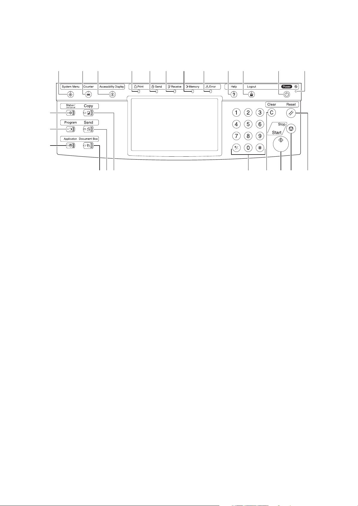
(2) Operation panel
2GN/2GP/2GR-2
1
5 9 10 11 12 13 14 15 16 17 18
2
3
4
2322212019678
Figure 1-1-2
1. System menu key/indicator
2. Status/Job cancel key/indicator
3. Program key/indicator
4. Application key/indicator
5. Counter key/indicator
6. Copy key/indicator
7. Send key/indicator
8. Document box key/indicator
9. Accessibility key/indicator
10. Print indicator
11. Send indicator
12. Receive indicator
13. Memory indicator
14. Error indicator
15. Help key/indicator
16. Logout key/indicator
17. Power key
18. Main power indicator
19. Numeric keys
20. Clear key
21. Start key/indicator
22. Stop key
23. Reset key
1-1-5
Page 20
2GN/2GP/2GR
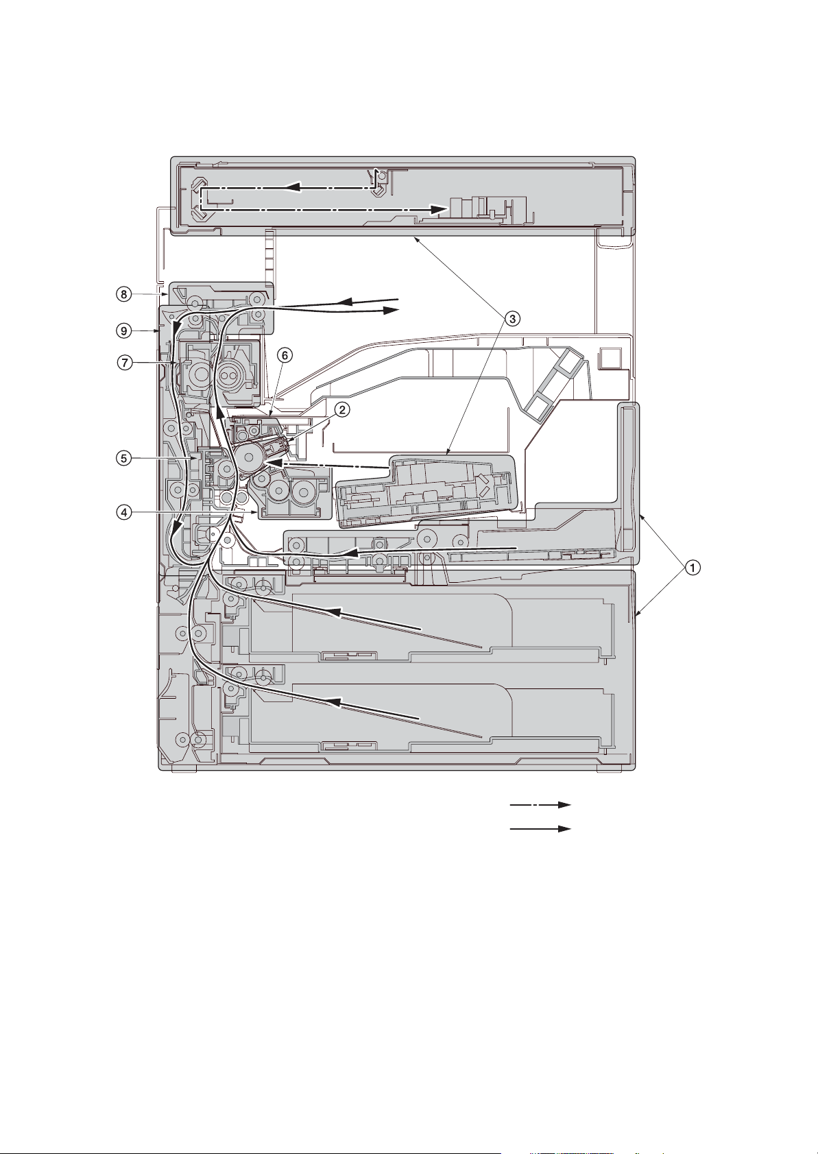
1-1-3 Machine cross section
1-1-6
Light path
Paper path
Figure 1-1-3 Machine cross section
1. Paper feed section
2. Main charging section
3. Optical section
4. Developing section
5. Transfer and separation section
6. Cleaning and charge erasing section
7. Fuser section
8. Eject and switchback section
9. Duplex section
Page 21
1-2 Installation
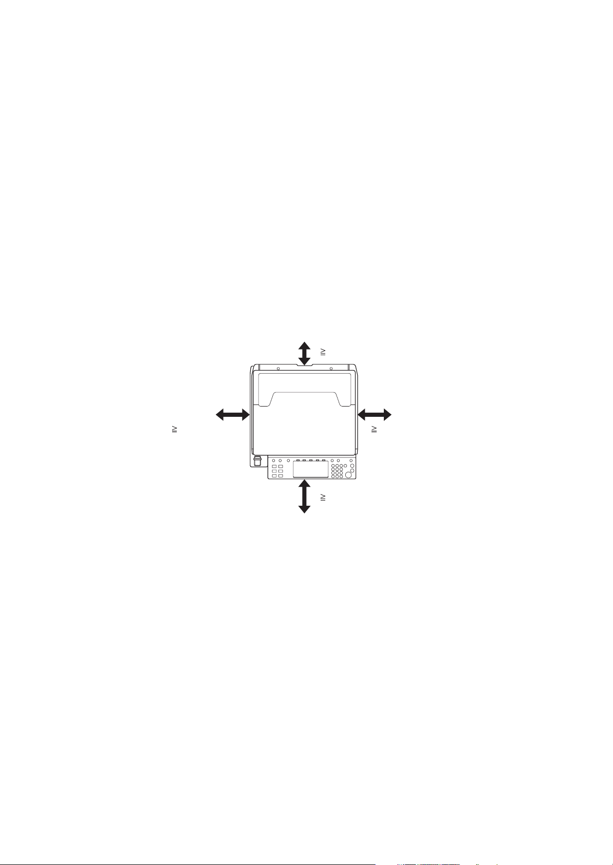
1-2-1 Installation environment
1. Temperature: 10 to 32.5°C/50 to 90.5°F
2. Humidity: 15 to 80%RH
3. Power supply: 120 V AC, 11.5 A
220 to 240 V AC, 6.3 A
4. Power source frequency: 50 Hz
5. Installation location
Avoid direct sunlight or bright lighting. Ensure that the photoconductor will not be exposed to direct sunlight or
other strong light when removing paper jams.
Avoid locations subject to high temperature and high humidity or low temperature and low humidity; an abrupt
change in the environmental temperature; and cool or hot, direct air.
Avoid places subject to dust and vibrations.
Choose a surface capable of supporting the weight of the machine.
Place the machine on a level surface (maximum allowance inclination: 1
Avoid air-borne substances that may adversely affect the machine or degrade the photoconductor, such as mercury, acidic of alkaline vapors, inorganic gasses, NOx, SOx gases and chlorine-based organic solvents.
Select a well-ventilated location.
6. Allow sufficient access for proper operation and maintenance of the machine.
Machine front: 1000 mm/39
Machine right: 300 mm/11
± 0.3%/60 Hz ± 0.3%
°).
3/8" Machine rear: 100 mm/3 15/16"
13/16" Machine left: 300 mm/11 13/16"
2GN/2GP/2GR-6
100 mm/3
300 mm/11 13/16" 300 mm/11 13/16"
1000 mm/39
15/16"
3/8"
Figure 1-2-1 Installation dimensions
1-2-1
Page 22
2GN/2GP/2GR-1
1-2-2 Unpacking and installation
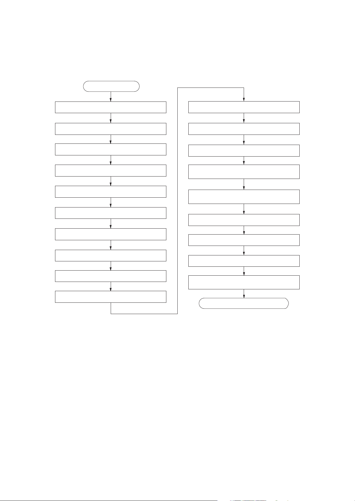
(1) Installation procedure
Start
Unpack.
Remove the tapes, spacers and pad.
Install the optional paper feeder.
Release the lever holding mirror 1 and 2 frames.
Release of cassette lift plate.
Load paper.
Install the toner container.
Install the waste toner box.
Install the optional original cover or the DP.
Connect the power cord.
Install the fixing brackets.
Install the stylus pen and penholder.
Carry out initial developer setting
(maintenance item U130).
Output an own-status report
(maintenance item U000).
Exit maintenance mode.
Print out the user setting list.
Make test copies.
Attaching the language label
(230 V specifications only).
Install other optional devices.
Completion of the machine installation.
1-2-2
Page 23
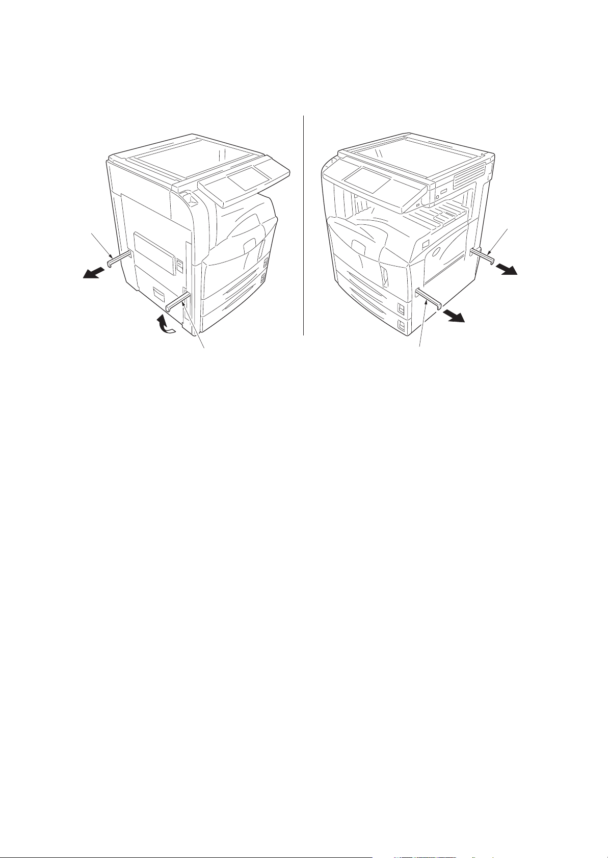
Moving the machine
When moving the machine, pull out the four handles on the right and left sides and hold them.
2GN/2GP/2GR-2
Handle
Handle
Handle
Handle
Figure 1-2-2
1-2-3
Page 24
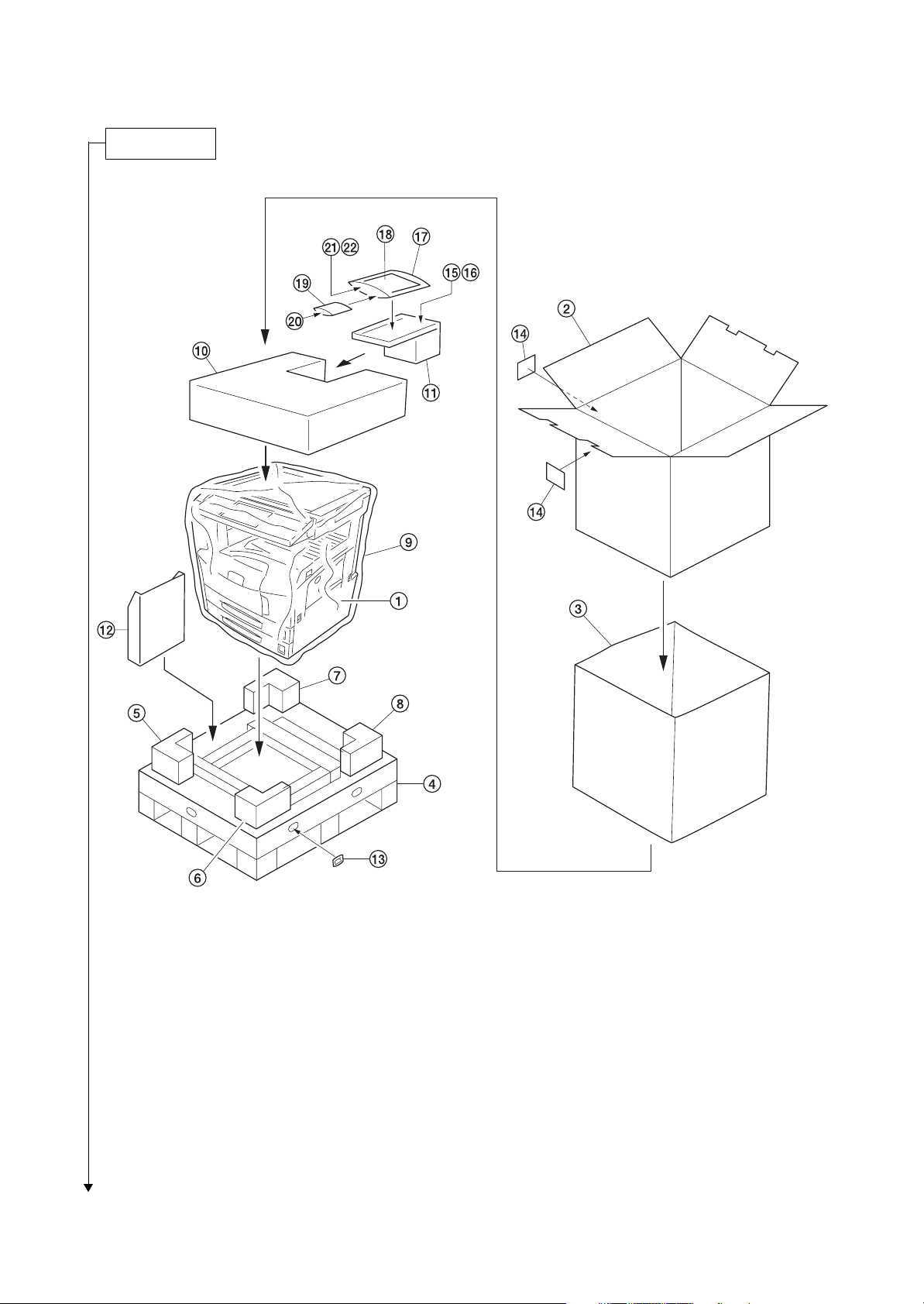
2GN/2GP/2GR-7
Unpacking.
1. Machine
2. Outer case
3. Inner frame
4. Skid
5. Bottom front left pad
6. Bottom front right pad
7. Bottom rear left pad
8. Bottom rear right pad
9. Machine cover
10. Upper pad
11. Spacer
12. Document tray
Caution: Place the machine on a level surface.
1-2-4
Figure 1-2-3 Unpacking
13. Hinge joints
14. Bar code labels
15. Power cord
16. Fixing brackets
17. Plastic bag
18. Operation guide
19. Plastic bag
20. Cursor pins
21. Stylus pen*
22. Penholder*
*: Europe and Asia Pacific only.
Page 25
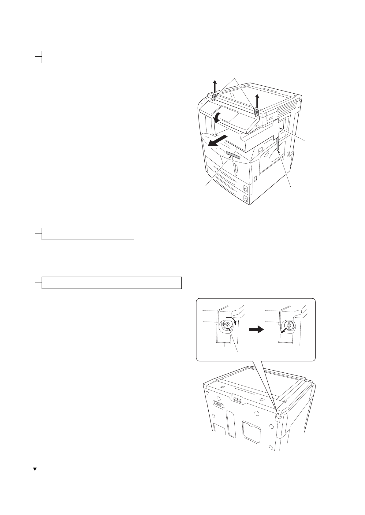
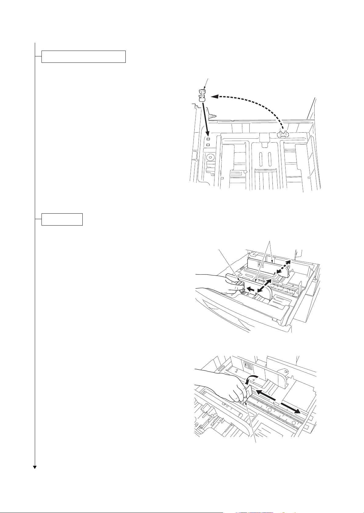
Remove the tapes, spacers and pad.
2GN/2GP/2GR-1
1. Remove two tapes.
2. Pull the lever and operation section is low-
ered.
3. Remove two spacers.
Remove waste textile on the operation
panel, if any.
4. Remove the pad.
Ta pe
Install the optional paper feeder.
1. Install the optional paper feeder as necessary.
2. Verify levelness at the four corners of the platen using a level gauge, and
adjust the level bolts at the bottom of the machine to optimize levelness.
Spacers
Pad
Ta pe
Figure 1-2-4
Release the lever holding mirror 1 and 2 frames.
1. Turn the lever of the machine rear side with
the tool to release the lever holding the mirror 1 and 2 frames.
Lever
Figure 1-2-5
1-2-5
Page 26
2GN/2GP/2GR-1
Release of cassette lift plate.
1. Pull cassette 1 and 2 out.
Remove the lift plate stopper from each cassette and attach it to the storage location.
When moving the machine, attach the lift
plate in original position.
Load paper.
1. Pull the cassette out.
2. Holding the paper width adjusting tab both
ends, move the paper width guides to fit the
paper size.
Lift plate stopper
Figure 1-2-6
Paper width guides
Paper width adjusting tab
3. Adjust the length adjustment plate to fit the
paper size.
1-2-6
Figure 1-2-7
Length adjustment plate
Figure 1-2-8
Page 27
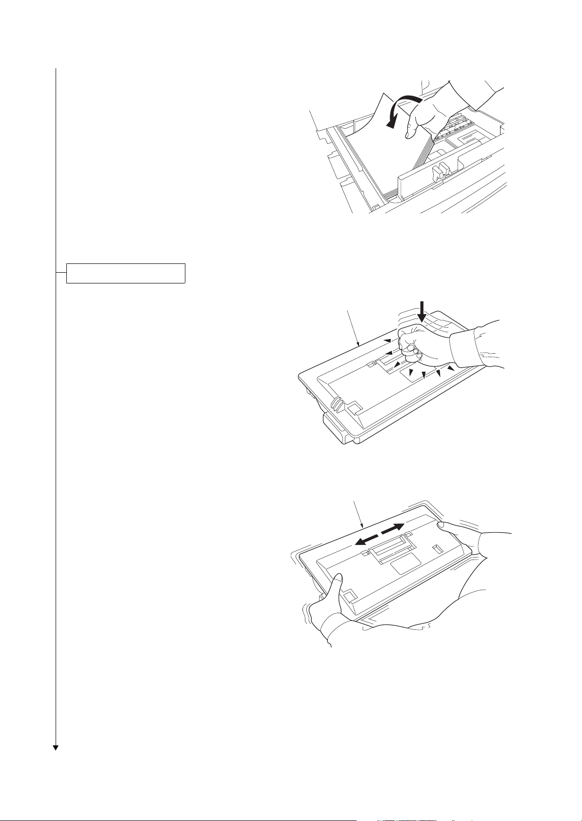
4. Align the paper flush against the left side of
the cassette.
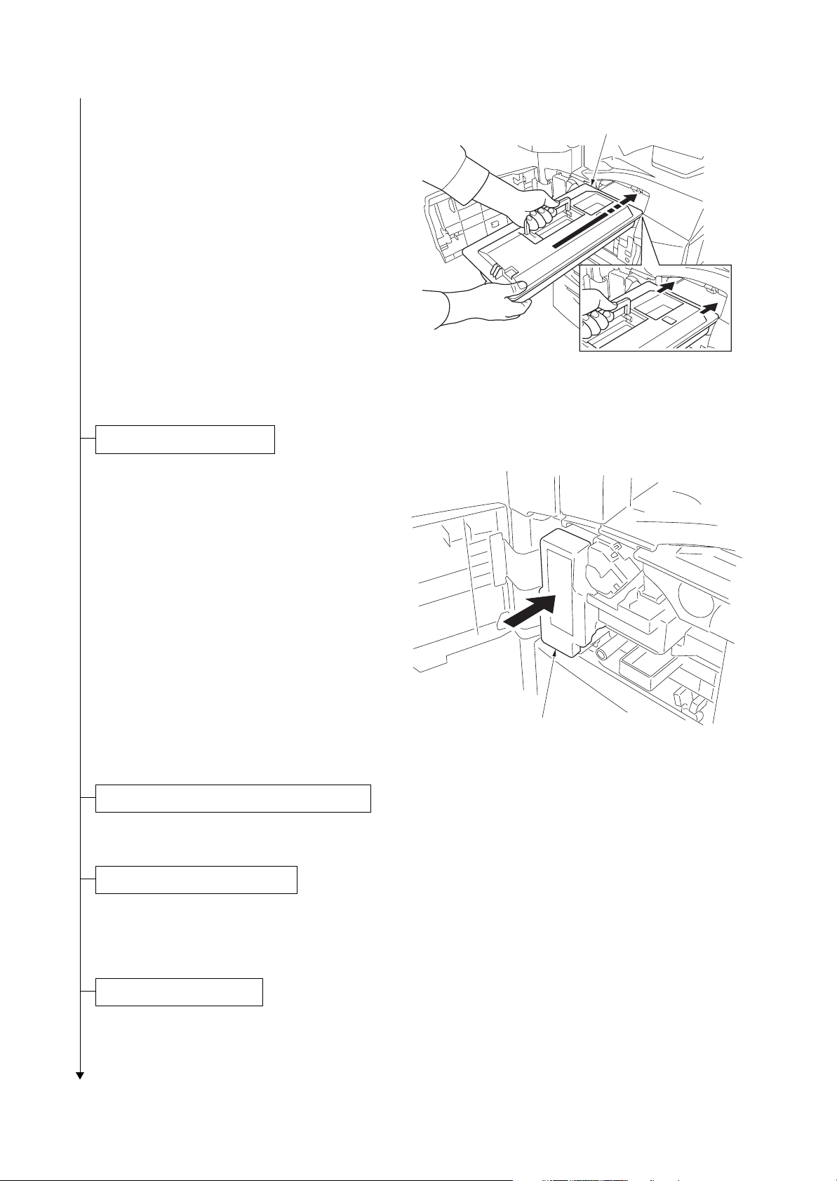
Install the toner container.
2GN/2GP/2GR
Figure 1-2-9
1. Open the front cover.
2. Tap the top of the toner container five to six
times.
3. Shake the toner container approximately 10
times in the horizontal direction to stir toner.
Toner container
Figure 1-2-10
Toner container
Figure 1-2-11
1-2-7
Page 28
2GN/2GP/2GR
4. Gently push the toner container into the
machine along the rails.
Push the container all the way into the
machine until it locks in place.
Install the waste toner box.
1. Install the waste toner box in the machine.
2. Close the front cover.
Toner container
Figure 1-2-12
Install the optional original cover or the DP.
1. Install the optional original cover or DP.
Install other optional devices.
1. Install the optional devices (job separator,
built-in finisher, document finisher and/or fax
kit etc.) as necessary.
Connect the power cord.
1. Connect the power cord to the connector on the machine.
2. Insert the power plug into the wall outlet.
1-2-8
Waste toner box
Figure 1-2-13
Page 29
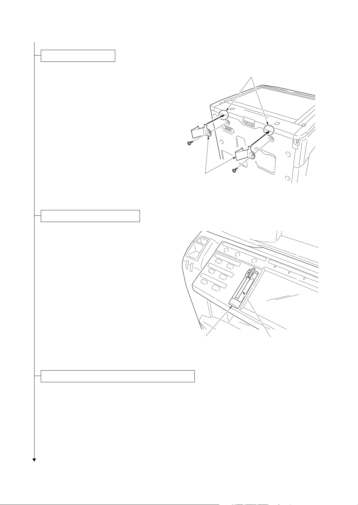
Install the fixing brackets.
2GN/2GP/2GR-1
1. Remove two screws from the rear cover.
2. Hook the catch of fixing brackets onto the
groove of round frame, and secure them
using two screws removed before step.
Install the stylus pen and penholder.
1. Attach the penholder and stylus pen to the
machine as necessary.
Grooves
Fixing brackets
Figure 1-2-14
Penholder
Stylus pen
Figure 1-2-15
Carry out initial developer setting (maintenance item U130).
1. Turn the main power switch on and press the status key.
2. Enter the maintenance mode by entering 10871087 using the numeric keys.
3. Enter 130 using the numeric keys and press the start key.
4. Press the start key to execute the maintenance item. The drive stops within approximately 5 minutes.
5. Press the stop key.
1-2-9
Page 30

2GN/2GP/2GR-1
Output an own-status report (maintenance item U000).
1. Enter 000 using the numeric keys and press the start key.
2. Select MAINTENANCE and press the start key to output a list of the current settings of the maintenance items.
3. Press the stop key.
Exit maintenance mode.
1. Enter 001 using the numeric keys and press the start key. The machine exits the maintenance mode.
Print out the user setting list.
1. Select [Report Print] to output the user various setting reports.
Make test copies.
1. Place an original and make test copies.
Attaching the language label (230 V specifications only).
1. According to need, attach the correspond language label.
Completion of the machine installation.
(2) Setting initial copy modes
Factory settings are as follows:
Maintenance
item No.
U253 Switching between double and single counts Double count
U260 Selecting the timing for copy counting After ejection
U285 Setting service status page ON
Contents Factory setting
1-2-10
U326 Setting the black line cleaning indication ON
U328 Side ejection setting OFF
U342 Setting the ejection restriction ON
U343 Switching between duplex/simplex copy mode OFF
Page 31

1-2-3 Installing the key counter (option)
r
Installing the key counter requires the following component:
Key counter (P/N 3025418011)
Key counter set (P/N 302A369708)
Supplied parts of key counter set:
Key counter socket assembly (P/N 3029236241)
Key counter cover (P/N 3066060011)
Key counter mount (P/N 3066060041)
Key counter retainer (P/N 302GR03020)
Key counter cover retainer (P/N 302GR03010)
One (1) M3 × 8 tap-tight P screw (P/N 5MBTPB3008PW++R)
Two (2) M4 × 10 tap-tight P screws (P/N 5MBTPB4010PW++R)
Two (2) M4 × 10 tap-tight S screws (P/N 5MBTPB4010TW++R)
Two (2) M3 × 6 bronze flat-head screws (P/N 7BB003306H)
One (1) M4 × 20 tap-tight S screw (P/N 7BB100420H)
One (1) M3 bronze nut (P/N 7BC1003055++H01)
One (1) M3 × 8 bronze binding screw (P/N B1B03080)
One (1) M4 × 30 tap-tight S screw (P/N B1B54300)
Five (5) M4 × 6 chrome TP screws (P/N B4A04060)
Two (2) M4 × 10 chrome TP screws (P/N B4A04100)
2GN/2GP/2GR-6
Procedure
1. Press the power key on the operation panel
to off. Make sure that the power indicator
and the memory indicator are off before
turning off the main power switch. And then
unplug the power cable from the wall outlet.
2. Fit the key counter socket assembly to the
key counter retainer using the two screws
and nut.
3. Fit the key counter mount to the key counter
cover using the two screws, and attach the
key counter retainer to the mount using the
two screws.
4. Remove the scanner right cover and the
upper right cover.
5. Cut out the aperture plate on the upper right
cover using nippers.
6. Pass the connecter of the machine through
the aperture and refit the upper right cover.
M4 x 6 screw
(B4A04060)
M3 nut
(7BC1003055++H01)
M4 x 6 screw
(B4A04060)
M3 x 6 flat-head
screws
(7BB003306H)
Key counter retainer
(302GR03020)
M4 x 6 screw
(B4A04060)
Key counter
socket assembly
(3029236241)
Figure 1-2-16
Scanner right cover
M4 x 6 screw
(B4A04060)
Key counter
mount
(3066060041)
Key counter cover
(3066060011)
Aperture
Connecto
Upper right cover
Figure 1-2-17
1-2-11
Page 32

2GN/2GP/2GR-6
7. Pass the connector of the machine through
the aperture in the key counter cover
retainer.
8. Insert the hook of the key counter cover
retainer in the slit of the upper right cover.
9. Fit the key counter cover retainer to the
machine using the M4 x 20 screw.
10. Refit the scanner right cover.
Upper right cover
Aperture
Key counter
cover retainer
M4 x 20 screw
(7BB100420H)
Connector
Hook
11. Insert the connector of the key counter signal cable into the connector of the machine.
12. Fit the key counter cover with the key
counter socket assembly inserted to the key
counter cover retainer using the M4 X 6
screw.
13. Insert the key counter into the key counter
socket assembly.
14. Turn the main power switch on and enter the
maintenance mode.
15. Run maintenance item U204 and select ON.
16. Exit the maintenance mode.
17. Check that the message requesting the key
counter to be inserted is displayed on the
touch panel when the key counter is pulled
out.
18. Check that the counter counts up as prints
are made.
Slit
Figure 1-2-18
Key counter
cover retainer
Connector
Key counter
signal cable
Figure 1-2-19
Key counter
cover retainer
Key conuter cover
M4 x 6 screw
(B4A04060)
1-2-12
Page 33

1-2-4 Installing the expanded memory (option)
Procedure
1. Press the power key on the operation panel
to off. Make sure that the power indicator
and the memory indicator are off before
turning off the main power switch. And then
unplug the power cable from the wall outlet.
2. Remove the screw and remove the memory
slot cover.
3. Open clamps on both ends of the memory
socket on the main PWB.
4. Insert the expanded memory into the memory socket so that the notch on the memory
align with the corresponding protrusion in
the slot.
The memory module is secured to the memory socket with the clamps.
5. Refit the memory slot cover.
6. Print a status page to check the memory
expansion (See page 1-3-6).
If memory expansion has been properly performed, information on the installed memory.
2GN/2GP/2GR-8
Memory slot
cover
Clamp
Expanded memory
Memory
socket
Protrusion
Notch
Clamp
Figure 1-2-20
1-2-13
Page 34

2GN/2GP/2GR-8
This page is intentionally left blank.
1-2-14
Page 35

2GN/2GP/2GR
1-3 Maintenance Mode
1-3-1 Maintenance mode
The machine is equipped with a maintenance function which can be used to maintain and service the machine.
(1) Executing a maintenance item
Start
Press the status key.
Yes
Enter “10871087” using
the numeric keys.
Enter the maintenance item
number using the cursor up/down keys
or numeric keys.
Press the start key.
The selected maintenance item is run.
Press the stop key.
Repeat the same
maintenance item?
Maintenance mode is entered.
The maintenance item is
selected.
Yes
No
Run another maintenance
item?
No
Enter “001” using the cursor
up/down keys or numeric keys
and press the start key.
End
Maintenance mode is exited.
1-3-1
Page 36

2GN/2GP/2GR-5
(2) Maintenance modes item list
Section Item
No.
Content of maintenance item Initial
setting*
General U000 Outputting an own-status report -
U001 Exiting the maintenance mode U002 Setting the factory default data U003 Setting the service telephone number ***************
U004 Displaying the machine number U005 Copying without paper U019 Displaying the ROM version -
Initialization U020 Initializing all data -
U021 Initializing counters and mode settings U022 Initializing backup memory U024 HDD formatting -
Drive, paper
feed, paper
conveying
and cooling
system
U030 Checking motor operation U031 Checking switches for paper conveying U032 Checking clutch operation U033 Checking solenoid operation U034 Adjusting the print start timing
Adjusting the leading edge registration
Adjusting the center line
245/0/-30/-30
490/0/0/0/0/0/0
U035 Setting the printing area for folio paper
Length/Width 330/210
U051 Adjusting the deflection in the paper 0/0/0/0
U053 Setting the adjustment of the motor speed
Drive motor
Eject motor
Polygon motor
Optical U061 Turning the exposure lamp on -
U063 Adjusting the shading position 0
U065 Adjusting the scanner magnification
Main scanning direction/auxiliary scanning direction 0/0
U066 Adjusting the scanner leading edge registration 0/0
U067 Adjusting the scanner center line 0/0
U068 Adjusting the scanning position for originals from the DP 0/0
U070 Adjusting the DP magnification 0/0/0
U071 Adjusting the DP scanning timing 0/0/0/0/0
U072 Adjusting the DP center line 0/0/0
U073 Checking scanner operation U074 Adjusting the DP input light luminosity 0/0/0
U080 Setting the economy mode -6
U081 Adjusting the correct exposure 0/0/0
U087 Setting DP reading position modification operation 175/170/160
U089 Outputting a MIP-PG pattern U093 Setting the exposure density gradient
Text and photo/Text/Photo 0/0/0
U099 Adjusting original size detection 105/105/105/60/60/60/
150/240
-5
*1
*1
*1
*1
*1
*1
2
*1
0
*1
*1
*1
*1
*1
*1
*1
*1
*1
*1
*1
*1
*1
*1
*1
*1
*Initial setting for executing U020, *1: The item initialized for executing U020, *2: The item initialized for executing U021
1-3-2
Page 37

2GN/2GP/2GR-7
Section Item
No.
Content of maintenance item Initial
setting*
High voltage U100 Setting the main high voltage -
U101
U102 Setting the cleaning interval for the main charger 5
Setting the other high voltages
Developing bias AC component frequency at image formation
Developing shift bias potential at image formation
Developing bias AC component duty at image formation
Transfer control voltage
Separation control voltage
28
1
50
130
20
*1
*1
*1
*1
*1
*1,*2
U109 Displaying the drum type U110 Checking the drum count U112 Setting toner refresh operation
*1
120
MODE1
*1
*1
*1
U114
Time of toner refreshment
Developing bias on time
Setting separation charger mode
700 (30 ppm)
540 (40/50 ppm)
U117 Checking the drum number U118 Displaying the drum history -
Developing U130 Initial setting for the developing unit -
U144 Setting toner loading operation MODE2
*1
U150 Checking sensors for toner U157 Checking/clearing the developing drive time U158 Checking the developing count -
Fuser and
cleaning
U161 Setting the fuser control temperature
Driving start temperature when warm-up starts
Control temperature for displaying [Ready for copying.]
Control temperature during printing
175 (30 ppm)
185 (40/50 ppm)
190 (30 ppm)
200 (40/50 ppm)
190 (30 ppm)
200 (40/50 ppm)
*1,*2
*1,*2
*1,*2
*1,*2
*1,*2
*1,*2
U163 Resetting the fuser problem data U167 Checking/clearing the fuser counts U196 Turning the fuser heater on U199 Checking the fuser temperature -
Operation
panel and
support
equipment
U200 Turning all LEDs on U201 Initializing the touch panel U202 Setting the KMAS host monitoring system U203 Checking DP operation U204 Setting the presence or absence of a key card or key counter OFF/COUNTER
*1,*2
U206 Setting the presence or absence of the coin vender U207 Checking the operation panel keys U208 Setting the paper size for the paper feeder Inch specifications: Letter
Metric specifications: A4
*1,*2
*1,*2
U220 Setting the trial functions U223 Operation panel lock Unlock
U234 Setting punch destination Inch specifications: INCH
*1,*2
*1
Metric specifications:
EUROPE METRIC
U236 Setting the limit for the ejection section of the built-in finisher OFF
U237 Setting finisher stack quantity 0/0
*1,*2
*1,*2
*1
U240 Checking the operation of the finisher -
*Initial setting for executing U020, *1: The item initialized for executing U020, *2: The item initialized for executing U021
1-3-3
Page 38

2GN/2GP/2GR-7
Section Item
Operation
panel and
support
equipment
No.
U241 Checking the operation of the switches of the finisher U243 Checking the operation of the DP motors U244 Checking the DP switches -
Content of maintenance item Initial
setting*
U245 Checking messages U246 Setting the finisher
3000-sheet document finisher
Centerfold unit
Built-in finisher
0/0/0/0/0/0
0/0/0/0/0/0/0/0
0/0/0
*1
*1
*1
U247 Setting the paper feed device -
Mode setting U250 Setting the maintenance cycle 400000 (30 ppm)
500000 (40/50 ppm)
*1,*2
*1,*2
U251 Checking/clearing the maintenance count U252 Setting the destination U253 Switching between double and single counts Double count
U260 Selecting the timing for copy counting After ejection
U265 Setting OEM purchaser code 0
U285 Setting service status page ON
U326 Setting the black line cleaning indication ON/8
U328 Side ejection setting OFF
U332 Setting the size conversion factor 1.0
*1
*1,*2
*1
*1
*1,*2
*1,*2
*1,*2
U341 Specific paper feed location setting for printing function U342 Setting the ejection restriction ON
U343 Switching between duplex/simplex copy mode OFF
*1,*2
*1,*2
U345 Setting the value for maintenance due indication -
Image
processing
U402 Adjusting margins of image printing 74/70/68/85/140/55
U403 Adjusting margins for scanning an original on the platen 2.0/2.0/2.0/2.0
U404 Adjusting margins for scanning an original from the DP 3.0/2.5/3.0/4.0
3.0/2.5/3.0/4.0
U407 Adjusting the leading edge registration for memory image
*1
0
*1
*1
*1
*1
printing
U411 Adjusting the scanner automatically U425 Setting the target -
Network
scanner
U510 Setting the enterprise mode Inch specifications: ON
Metric specifications: OFF
*1,*2
*1,*2
Others U901 Checking/clearing copy counts by paper feed locations -
U902 Checking/clearing the punch-hole scrap counter 35000/0
*1,*2
U903 Checking/clearing the paper jam counts U904 Checking/clearing the service call counts U905 Checking/clearing counts by optional devices U906 Resetting partial operation control U908 Checking the total counter value U910 Clearing the black ratio data U911 Checking/clearing copy counts by paper sizes U917 Setting backup data reading/writing U920 Checking the copy counts U927 Clearing the all copy counts and machine life counts (one
-
time only)
*Initial setting for executing U020, *1: The item initialized for executing U020, *2: The item initialized for executing U021
1-3-4
Page 39

2GN/2GP/2GR-7
Section Item
No.
Content of maintenance item Initial
setting*
Others U928 Checking machine life counts -
U933 Setting the fax backup kit U935 Relay board maintenance U942 Setting of deflection for feeding from DP 0/0
U943 Adjusting the prevent appearance of back side image 50
U984 Checking the developing unit number U985 Displaying the developing unit history U989 HDD scandisk U990 Checking/clearing the time for the exposure lamp to light U991 Checking the scanner count U993 Outputting a VTC-PG pattern -
*1
*1
*Initial setting for executing U020, *1: The item initialized for executing U020, *2: The item initialized for executing U021
1-3-5
Page 40

2GN/2GP/2GR-7
(3) Contents of the maintenance mode items
Maintenance
item No.
U000
Description
Outputting an own-status report
Description
Outputs lists of the current settings of the maintenance items, and paper jam and service call occurrences.
Outputs the event log or service status page.
Printing a report is disabled either when a job is remaining in the buffer or when [Pause All Print Jobs] is
pressed to halt printing.
Purpose
To check the current setting of the maintenance items, or paper jam or service call occurrences. Before initializing or replacing the backup RAM, output a list of the current settings of the maintenance items to reenter the
settings after initialization or replacement.
Method
1. Press the start key.
2. Select the item to be output.
Display Output list
MAINTENANCE List of the current settings of the maintenance modes
EVENT LOG Outputs the event log
SERVICE STATUS Outputs the service status page
3. Press the start key. The interrupt print mode is entered and a list is output.
When A4/Letter paper is available, a report of this size is output. If not, specify the paper feed location.
When output is complete, the screen for selecting an item is displayed.
Event log
Event Log
MFP
Firmware version 2GR_2000.001.036
(1)
(3)
Paper Jam Log
#
Count.
16
1876543
15
166554
14
4988
13
4988
12
4988
11
4988
10
110 3
9
110 3
8
110 3
7
110 3
6
1027
5
1027
4
1027
3
1027
2
550
1
28
(7)
Counter Log
J04:000
(f) (g) (h)
J05:000
J09:000
J10:000
J11:002
J12:000
J13:000
J14:000
J15:000
J20:000
J21:000
J22:000
J23:000
J30:002
J40:002
J41:000
J42:000
J43:000
Event
Descriprions
10.01.08.01.01
10.01.08.01.02
10.01.08.01.01
10.01.08.01.02
10.01.08.01.01
10.01.08.01.02
10. 01. 08. 01. 01
10.01.08.01.01
(a) (b) (c) (d) (e)
10.01.08.01.01
12.03.08.01.01
12.03.08.01.01
12.03.08.01.01
12.03.0A.01.01
12.03.08.01.01
12.03.08.01.02
12.03.0A.01.01
12.03.08.01.01
J70:000
J71:000
J72:000
J73:000
J74:002
J75:002
J76:000
J78:000
J80:000
2006.04.17
(2)
J93:002
J94:000
J95:000
J96:000
(4)
Service Call Log
#
8
7
6
5
4
3
2
1
Maintenance Log
(5)
#
8
7
6
5
4
3
2
1
Unknown toner Log
(6)
#
5
4
3
2
1
C0101:001
C0102:001
C0107:001
C0108:001
C0220:001
C2002:001
C2030:001
C2031:001
C2222:001
Count.
1881214
178944
5296
5295
2099
1054
809
30
Count.
1045571
704511
7045
3454
3454
3454
417
35
Count.
3454
3454
3454
417
35
C2223:001
C2225:001
C2228:001
C2259:001
C3003:001
C3411:001
C3412:001
C3421:001
C3431:001
Service Code
F0.0030
01.1010
F0.4000
F0.3100
01.2000
01.2000
01.2500
01.2500
Item
01.00
01.00
01.00
01.00
02.00
02.00
02.00
02.20
Item
01.00
01.00
01.00
01.00
01.00
C3502:001
C3503:001
C3552:001
C3553:001
M00:01
M00:01
1-3-6
Figure 1-3-1
Page 41

2GN/2GP/2GR-6
Maintenance
item No.
U000 Detail of event log
No. Items Description
(1) System version
(2) System date
(3) Paper Jam Log # Count. Event
Description
Remembers 1 to 16 of
occurrence. If the
occurrence of the previous paper jam is less
than 16, all of the paper
jams are logged. When
the occurrence
excesseds 16, the oldest occurrence is
removed.
(a) Cause of paper jam (Hexadecimal)
04: Cover open
05: Secondary paper feed does not start
09: 3000-sheet paper feeder sequence error jam
10: No paper feed from cassette 1
11: No paper feed from cassette 2
12: No paper feed from optional cassette 3
13: No paper feed from optional cassette 4
14: No paper feed from MP tray
15: Jam in paper feeder horizontal paper conveying section 1
16: Jam in paper feeder horizontal paper conveying section 2
17: Jam in paper feeder horizontal paper conveying section 3
18: Misfeed in vertical paper conveying section
19: Misfeed in paper feeder vertical paper conveying section
20: Misfeed in MP tray vertical paper conveying section
21: Multiple sheets in paper feed section
22: Multiple sheets in vertical conveying section
23: Multiple sheets in MP tray conveying section
30: Misfeed in registration/transfer section
40: Misfeed in fuser section (MP tray)
41: Misfeed in fuser section (cassette 1)
42: Misfeed in fuser section (cassette 2)
43: Misfeed in fuser section (optional cassette 3)
44: Misfeed in fuser section (optional cassette 4)
46: Misfeed in fuser section (optional 3000-sheet paper feeder)
47: Misfeed in fuser section (duplex section)
50: Misfeed in eject section
51: Misfeed in job separator eject section
52: Misfeed in feedshift section
60: Duplex paper conveying section 1
61: Duplex paper conveying section 2
70: No original feed
71: An original jam in the original feed/conveying section 1
72: An original jam in the original feed/conveying section 2
73: An original jam in the original conveying section
74: An original jam in the original registration section
75: An original jam in the original registration section
76: An original jam in the original feed/conveying section
78: Document processor top cover open
80: Jam between the finisher and machine (3000-sheet document finisher)
81: Paper entry sensor nonarrival jam
The total page count at
the time of the paper
jam.
Log code (2 digit, hexadecimal, 5 categories)
(a) Cause of a paper
jam
(b) Paper source
(c) Paper size
(d) Paper type
(e) Paper eject
1-3-7
Page 42

2GN/2GP/2GR-7
Maintenance
item No.
U000
Description
No. Items Description
(3)
Paper Jam Log 82: Jam in stapler
cont.
83: Exit sensor stay jam
84: Jam in eject section of right sub tray (3000-sheet document finisher)
85: Jam in eject section of left sub tray (3000-sheet document finisher)
86: Jam in eject section of internal tray 1 (3000-sheet document finisher)
87: Jam in eject section of internal tray 2 (3000-sheet document finisher)
88: Jam in eject section of main tray (3000-sheet document finisher)
89: Jam in centerfold unit (3000-sheet document finisher)
90: Jam in mailbox (3000-sheet document finisher)
91: Finisher cover open
92: Exit sensor non-arrival jam (document finisher)
93: Reverse sensor jam (document finisher)
94: Paper entry sensor stay/remaining jam (document finisher)
95: Paper conveying sensor jam (document finisher)
96: Jam between the built-in finisher and machine (built-in finisher)
(b) Detail of paper source (Hexadecimal)
00: MP tray
01: Cassette 1
02: Cassette 2
03: Cassette 3 (paper feeder/3000-sheet paper feeder)
04: Cassette 4 (paper feeder)
05 - 09: Reserved
(c) Detail of paper size (Hexadecimal)
01: Monarch
02: Business
03: International DL
04: International C5
05: Executive
06: Letter-R
86: Letter-E
07: Legal
08: A4R
88: A4E
09: B5R
89: B5E
0A: A3
0B: B4
(d) Detail of paper type (Hexadecimal)
00: (Not specified)
01: Plain
02: Transparency
03: Preprinted
04: Labels
05: Bond
06: Recycled
07: Vellum
08: Rough
0C: Ledger
0D: A5R
8D: A5E
0E: A6
0F: B6
10: Commercial #9
11: Commercial #6
12: ISO B5
13: Custom size
1E: C4
1F: Postcard
20: Reply-paid postcard
21: Oficio II
22: Special 1
09: Letterhead
0A: Color
0B: Prepunched
0C: Envelope
0D: Cardstock
0E: Coated
0F: 2nd side
10: Media 16
11: High quality
23: Special 2
24: A3 wide
25: Ledger wide
26: Full bleed paper
(12 x 8)
27: 8K
28: 16K-R
A8: 16K-E
32: Statement-R
B2: Statement-E
33: Folio
34: Western type 2
35: Western type 4
15: Custom 1
16: Custom 2
17: Custom 3
18: Custom 4
19: Custom 5
1A: Custom 6
1B: Custom 7
1C: Custom 8
1-3-8
Page 43

2GN/2GP/2GR-7
Maintenance
item No.
U000
Description
No. Items Description
(3)
cont.
Paper Jam Log
(4) Service Call Log # Count. Service Code
(5) Maintenance Log # Count. Item
(e) Detail of paper exit location (Hexadecimal)
01: Face down (FD)
02: Face up (FU)/
Document finisher face up (FU)/
3000-sheet document finisher left sub tray (FU)
03: Document finisher face down (FD)
04: Reserved
05: Reserved
06: 3000-sheet document finisher right sub tray (FU)
07: 3000-sheet document finisher left sub tray (FD)
09: 3000-sheet document finisher right sub tray (FD)
0B: Mailbox tray 1 (FD)
0C: Mailbox tray 1 (FU)
0D: Reserved
0E: Reserved
15: Mailbox tray 2 (FD)
16: Mailbox tray 2 (FU)
1F: Mailbox tray 3 (FD)
20: Mailbox tray 3 (FU)
29: Mailbox tray 4 (FD)
2A: Mailbox tray 4 (FU)
33: Mailbox tray 5 (FD)
34: Mailbox tray 5 (FU)
3D: Mailbox tray 6 (FD)
3E: Mailbox tray 6 (FU)
47: Mailbox tray 7 (FD)
48: Mailbox tray 7 (FU)
Remembers 1 to 8 of
occurrence of self diagnostics error. If the
occurrence of the previous diagnostics error is
less than 8, all of the
diagnostics errors are
logged.
Remembers 1 to 8 of
occurrence of replacement. If the occurrence
of the previous replacement of toner container
is less than 8, all of the
occurrences of replacement are logged.
The total page count at
the time of the self
diagnostics error.
The total page count at
the time of the replacement of the toner container.
Self diagnostic error
code
(See page 1-4-22)
Example:
01.6000
01: Self diagnostic
error
6000: Self diagnostic
error code number
Code of maintenance
replacing item (1 byte,
2 categories)
First byte (Replacing
item)
01: Toner container
02: Maintenance kit
Second byte (Type of
replacing item)
00: (fixed)
1-3-9
Page 44

2GN/2GP/2GR-7
Maintenance
item No.
U000
Description
No. Items Description
(6) Unknown Toner Log # Count. Item
(7) Counter Log
Comprised of three
log counters including paper jams, self
diagnostics errors,
and replacement of
the toner container.
Remembers 1 to 5 of
occurrence of unknown
toner detection. If the
occurrence of the previous unknown toner
detection is less than 5,
all of the unknown
toner detection are
logged.
(f) Paper jam (g) Self diagnostic error (h) Maintenance item
Indicates the log
counter of paper jams
depending on location.
Refer to Paper Jam
Log.
All instances including
those are not occurred
are displayed.
The total page count at
the time of the [Toner
Empty] error with using
an unknown toner container.
Indicates the log
counter of self diagnostics errors depending
on cause. (See P.1-4-
22)
Example:
C6000: 4
Self diagnostics error
6000 has happened
four times.
Unkown toner log code
(1 byte, 2 categories)
First byte
01: Fixed (Toner container)
Second byte
00: Fixed (Black)
Indicates the log
counter depending on
the maintenance item
for maintenance.
T: Toner container
00: Black
M: Maintenance kit
00: (fixed)
Example:
T00: 1
The toner container has
been replaced once.
replacing
1-3-10
Page 45

2GN/2GP/2GR-2
Maintenance
item No.
U000
Service status page (1)
Service Status Page
MFP
(1)
Firmware version 2GR_2000.001.001
Controller Information
Memory Status
(3)
Option Slot1
(4)
Option Slot2
(5)
To ta l
Time
Local Time Zone
(6)
(7)
Data and Time
(8)
Time Server
(9)
FRPO Status
User Top Margin
User Left Margin
User Page Length
(2)
524288KB
524288KB
1048576KB
+01:00_Amsterdam
10/27/2005 09:06
10.183.53.13
A1+A2/100
A3+A4/100
A5+A6/100
Description
2007.01.17
0.00
0.00
17.30
Auto Continue Mode
Auto Continue TimerY0Y1
00
06
1
Figure 1-3-2
Detail of service status page
No. Description Supplement
(1) System version
(2) System date
(3) Slot 1 RAM size
(4) Slot 2 RAM size
(5) Total RAM size
(6) Local time zone
(7) Report output date Day/Month/Year hour:minute
(8) NTP server name
(9) FRPO setting
1-3-11
Page 46

2GN/2GP/2GR-2
Maintenance
item No.
U000
Service status page (2)
Service Status Page
MFP
Firmware version 2GR_2000.001.001
Engine Information
(10)
Engine ROM Version
(11)
Front Panel ROM Version
(12)
NVRAM Version
(13)
Scanner Version
(14)
FAX Slot1
FAX BOOT Version
FAX APL Version
FAX IPL Version
(15)
Serial No.
(16)
MAC Address
Toner Coverage (%)
(17)
Period (07/11/2005 - 07/12/2005 08:05)
(18)
Usage Page (A4/Letter Conversion) 3043.50
(19)
Average (%)
To ta l
Copy
Printer
FAX
(20)
Last Page (%)
Installed Options
(21)
Document Processor
(22)
Paper Feeder
(23)
Finisher
Mail Box
(24)
Job Separator
(25)
Memory Card
(26)
PDF Expansion Kit
(27)
Fax Backup Kit
(28)
Security Kit
(29)
Data Security Kit (C) Software
(30)
Security Library Version 0.50
(35)
1/2
(36)
245/490
(37)
0/-30/-30/-30
(38)
0/0/0/0
(39)
0/50/0/50/10/61/8/11
(40)
F00/U00
(41)
12345678/11223344/00001234abcd567800001234abcd5678/01234567890123456789012345678901/0008/00/07
(42)
0000000000/F80C001A37/302A183C00/000100013D/8791BFC305/0000003100/000F5D0000/01FD000000/
0000000FB7/0000000000/0000260000/0000000000/0000000000/0000008400/0000000000/011F000F51/
8F0F000000/0000000000/0000000000/0000000000/0000000000/0000000000/0000000F/
Description
2006.01.17
2GR_1000.003.001
2GR_A000.001.019
_Bb04B29_Bb04B29
2GR_1200.001.088
2GR_5000.001.001
2GR_5100.001.001
2GR_5200.001.001
AFZ3123456
00:C0:EE:D0:01:0D
2.90
3.56
2.87
3.52
2.80
Installed
Cassette
3000-Finisher
Not Installed
Installed
Not Installed
Installed
Not Installed
Installed
Counter
(31)
Printed
Total Printed Pages
Copier
Printer
FAX
(32)
Scanned
Total Scanned Pages
Copier
Other
(33)
Paper Size
A3
A4
A5
B4
B5
Ledger
Folio
Legal
Letter
Statement
Other
(34)
FAX InfomationSiot1/Slot2
Rings (Normal)
Rings (FAX/TEL)
Rings (TAD)
TX SPEED
RX SPEED
ECM TX
ECM RX
V.34
REG.G3 TX EQR
REG.G3 RX EQR
RX MODEM LEVEL
SGL LVL MODEM
631
11
620
0
1
0
1
69
539
0
36
0
7
0
0
0
0
0
3
3
3
V.29 9600bps
9600bps
ON
OFF
TX
4db
0db
-43dBm
-9dBm
1-3-12
2
Figure 1-3-3
Page 47

2GN/2GP/2GR-2
Maintenance
item No.
U000 Detail of service status page
No. Description Supplement
(10) Engine ROM version
(11) Operation panel ROM version
(12) NV RAM version _ Bb 04B29 _ Bb 04B29
(13) Scanner version
(14) Fax firmware version This item is printed only when the optional fax kit is
(15) Serial No. 10 digits
(16) Mac address
(17) Cleared date and output date
(18) Page of relation to the A4/Letter
(19) Average coverage
(20) Coverage on the final output page
(21) Presence or absence of the optional DPInstalled
(22) Presence or absence of the optional
paper feeder
(23) Presence or absence of the optional
document finisher
(24) Presence or absence of the optional
job separator
(25) Presence or absence of the memory
card
(26) Presence or absence of the optional
PDF upgrade kit
Description
(a) (b) (c) (d) (e) (f)
(a) Consistency of the present software version and the
database
_ (underscore): OK
* (Asterisk): NG
(b) Database version
(c) The oldest time stamp of database version
(d) Consistency of the present software version and the
ME firmware version
_ (underscore): OK
* (Asterisk): NG
(e) ME firmware version
(f) The oldest time stamp of the ME database version
Normal if (a) and (d) are underscored, and (b) and (e)
are identical with (c) and (f).
installed.
Total/Copy/Printer/Fax
Not Installed
Cassette: Paper feeder
LCF: 3000-sheet paper feeder
Not Installed
Inner Finisher: Built-in finisher
3000-Finisher: 3000-sheet document finisher
1000-Finisher: Document finisher
Not Installed
Installed
Not Installed
Installed
Not Installed
Installed: The formal version is installed
Not Installed: The PDF upgrade kit is not installed
Trial Version(xx/xx/xx): A trial version is installed
(27) Presence or absence of the optional
fax backup kit
(28) Presence or absence of the optional
security kit
Installed
Not Installed
Installed
Not Installed
1-3-13
Page 48

2GN/2GP/2GR-2
Maintenance
item No.
U000
Description
No. Description Supplement
(29) Identification name for the security kit
(30) Security kit version
(31) Printed page counts Total/Copy/Printer/Fax
(32) Scanned page counts Total/Copy/Other
(33) Counts by paper sizes
(34) Fax kit information This item is printed only when the optional fax kit is
installed.
(35) Destination information/Area informa-
tion
(36) Printable area setting
(37) Top offset for each bin MP tray/Cassette 2/Cassette 3/Cassette 4
(38) Left offset for each bin MP tray/Cassette 2/Cassette 3/Cassette 4
(39) Margin/Page length/Page width
settings
(40) Panel lock information/USB information Panel lock
(41) RFID information
(42) Maintenance information
Top margin integer part/Top margin decimal part/
Left margin integer part/Left margin decimal part/
Page length integer part/Page length decimal part/
Page width integer part/Page width decimal part
0: OFF/1: Partial lock/2: Full lock
USB
0: Not installed/1: Full speed/2: Hi speed
U001
U002
Completion
Press the stop key. The screen for selecting a maintenance item No. is displayed.
Exiting the maintenance mode
Description
Exits the maintenance mode and returns to the normal copy mode.
Purpose
To exit the maintenance mode.
Method
Press the start key. The normal copy mode is entered.
Setting the factory default data
Description
Restores the machine conditions to the factory default settings.
Purpose
To move the mirror frame of the scanner to the position for transport (position in which the frame can be fixed).
Method
1. Press the start key.
2. Press [MODE1(ALL)] on the touch panel.
3. Press the start key.
The mirror frame of the scanner returns to the position for transport.
4. Turn the main power switch off and on.
An error code is displayed in case of an intialization error. Refer to the table of the error codes on P.1-3-17.
When ERROR 09 occurred, turn main power switch off then on, format the hard disk using maintenance
item U024, and execute initialization using maintenance item U002. For other errors occurred, turn main
power switch off then on, and execute initialization using maintenance item U002.
1-3-14
Page 49

2GN/2GP/2GR-1
Maintenance
item No.
U003
U004
U005
Description
Setting the service telephone number
Description
Sets the telephone number to be displayed when a service call code is detected.
Purpose
To set the telephone number to call service when installing the machine.
Method
Press the start key. The currently set telephone number is displayed.
Setting
1. Press the start key.
The keys to enter the number are displayed on the touch panel.
2. Enter a telephone number (up to 15 digits).
3. Press the start key. The setting is set.
Completion
Press the stop key. The screen for selecting a maintenance item No. is displayed.
Displaying the machine number
Description
Displays the machine number.
Purpose
To check the machine number.
Method
Press the start key. The currently machine number is displayed.
Completion
Press the stop key. The screen for selecting a maintenance item No. is displayed.
Copying without paper
Description
Simulates the copy operation without paper feed.
Purpose
To check the overall operation of the machine.
Method
1. Press the start key.
2. Select the item to be operated.
Display Operation
MFP Only the machine operates.
MFP + DP Both the machine and DP operate (continuous operation).
3. Press the start key.
4. Press the system menu key. The copy mode screen is displayed.
5. Set the operation conditions required on the copy mode screen. Changes in the following settings can
be made.
Paper feed locations
Magnifications
Simplex or duplex copy mode
Number of copies: in simplex copy mode, continuous copying is performed when set to 999; in duplex
copy mode, continuous copying is performed regardless of the setting.
Copy density
Keys on the operation panel
6. To control the paper feed pulley, remove all the paper in the drawers, or the drawers. With the paper
present, the paper feed pulley does not operate.
7. Press the start key. The operation starts.
Copy operation is simulated without paper under the set conditions.
To stop continuous operation, press the stop key.
8. To return to the screen for selecting an item, press the system menu key.
Completion
Press the stop key. The screen for selecting a maintenance item No. is displayed.
1-3-15
Page 50

2GN/2GP/2GR-2
Maintenance
item No.
U019
Description
Displaying the ROM version
Description
Displays the part number of the ROM fitted to each PWB.
Purpose
To check the part number or to decide, if the newest version of ROM is installed.
Method
1. Press the start key. The ROM version are displayed.
2. Change the screen using the cursor up/down keys.
Display Description
MAIN Main PWB ROM IC
MMI Operation PWB ROM IC
ENGINE Engine PWB ROM IC
ENGINE BOOT Engine PWB booting
SCANNER Scanner PWB ROM IC
OPTION LANGUAGE Optional language ROM IC
DICTIONARY DP Optional DP main PWB ROM IC
LCF Optional 3000-sheet paper feeder main PWB ROM IC
OPTION CASSETTE Optional paper feeder main PWB ROM IC
DF MAIN Optional 3000-sheet document finisher main PWB ROM IC
DF MTRAY Optional 3000-sheet document finisher internal tray PWB
ROM IC
DF SADDLE Optional centerfold main PWB ROM IC
DF MAILBOX Optional mailbox main PWB ROM IC
INNER DF Optional built-in finisher main PWB ROM IC
SIMPLE DF MAIN Optional document sheet finisher main PWB ROM IC
FAX BOOT1 Optional fax control PWB booting (port 1)
FAX APL1 Optional fax control PWB APL (port 1)
FAX IPL1 Optional fax control PWB IPL (port 1)
FAX BOOT2 Fax control PWB booting (port 2: optional dual FAX)
FAX APL2 Fax control PWB APL (port 2: optional dual FAX)
FAX IPL2 Fax control PWB IPL (port 2: optional dual FAX)
1-3-16
Completion
Press the stop key. The screen for selecting a maintenance item No. is displayed.
Page 51

2GN/2GP/2GR-2
Maintenance
item No.
U020
Description
Initializing all data
Description
Initializes all the backup RAM on the main PWB to return to the original settings.
Refer to *1 of the maintenance mode item list about the item initialized.
Also, initializes the settings with the system menu in order to restore default settings simultaneously.
Reregister the fax settings since the settings are initialized when the optional fax kit is installed.
Purpose
To be executed as required.
Caution
Run the maintenance item U411 (Adjusting the scanner automatically) after initialization (see page 1-3-72).
Method
1. Press the start key.
2. Select the destination.
Display Description
INCH Inch (North America) specifications
EUROPE METRIC Metric (Europe) specifications
ASIA PACIFIC Metric (Asia Pacific) specifications
3. Press the start key. All data in the backup RAM is initialized.
4. Turn the main power switch off and on.
An error code is displayed in case of an intialization error.
When ERROR 09 occurred, turn main power switch off then on, format the hard disk using maintenance
item U024, and execute initialization using maintenance item U020. For other errors occurred, turn main
power switch off then on, and execute initialization using maintenance item U020.
Error codes
Codes Description
ERROR 01 Configuration initialization error
ERROR 02 Counter initialization error
ERROR 03 One-touch initialization error
ERROR 04 Panel program initialization error
ERROR 05 Event log initialization error
ERROR 06 Account initialization error
ERROR 07 Address book initialization error
ERROR 08 Department initialization error
ERROR 09 Document box initialization error
ERROR 0a Permissibility initialization error
ERROR 0b Job log initialization error
ERROR 20 Engine initialization error
ERROR 40 Scanner initialization error
1-3-17
Page 52

2GN/2GP/2GR-2
Maintenance
item No.
U021
U022
Description
Initializing counters and mode settings
Description
Initializes all settings, except those pertinent to the type of machine, namely each counter, service call history
and mode setting. Also initializes backup RAM according to region specification selected in maintenance item
U252 Setting the destination.
Refer to *2 of the maintenance mode item list about the item initialized.
Purpose
To return the machine settings to their factory default.
Method
1. Press the start key.
2. Press [EXECUTE] on the touch panel.
3. Press the start key. All data other than that for adjustments due to variations between machines is initialized based on the destination setting.
4. Turn the main power switch off and on.
An error code is displayed in case of an intialization error. Refer to the table of the error codes on P.1-3-17.
When ERROR 09 occurred, turn main power switch off then on, format the hard disk using maintenance
item U024, and execute initialization using maintenance item U021. For other errors occurred, turn main
power switch off then on, and execute initialization using maintenance item U021.
Initializing backup memory
Description
Initializes only the backup data for image processing.
Also, initializes the settings with the system menu in order to restore default settings simultaneously when
[MAIN+ENGINE] is selected.
Reregister the fax settings since the settings are initialized when the optional fax kit is installed.
Purpose
To be executed as required.
Caution
Run the maintenance item U411 (Adjusting the scanner automatically) after initialization the backup data of
scanner PWB or DP main PWB (see page 1-3-72).
Method
1. Press the start key.
2. Select the item to initialize.
Display Description
MAIN+ENGINE Initialize the backup data of main PWB and engine PWB.
SCANNER Initialize the backup data of scanner PWB.
DP Initialize the backup data of DP main PWB.
1-3-18
3. When selecting [MAIN+ENGINE], select the destination.
Display Description
INCH Inch (North America) specifications
EUROPE METRIC Metric (Europe) specifications
ASIA PACIFIC Metric (Asia Pacific) specifications
4. Press the start key. All data in the backup RAM is initialized.
5. Turn the main power switch off and on.
An error code is displayed in case of an intialization error. Refer to the table of the error codes on P.1-3-17.
When ERROR 09 occurred, turn main power switch off then on, format the hard disk using maintenance
item U024, and execute initialization using maintenance item U022. For other errors occurred, turn main
power switch off then on, and execute initialization using maintenance item U022.
Page 53

2GN/2GP/2GR-2
Maintenance
item No.
U024
U030
Description
HDD formatting
Description
Initializes the HDD.
In addition, the following settings are also initialized by initializing the HDD.
System menu (user login administration, job accounting, address book, one-touch keys and document box
etc.), shortcuts and panel programs
Purpose
To initialize the HDD when replacing the HDD after shipping.
Method
1. Press the start key.
2. Press [EXECUTE] on the touch panel.
3. Press the start key to initialize the hard disk.
4. Turn the main power switch off and on.
Checking motor operation
Description
Drives each motor.
Purpose
To check the operation of each motor.
Method
1. Press the start key.
2. Select the motor to be operated.
3. Press the start key. The operation starts.
Display Operation
FEED Paper feed motor operates
MAIN Drive motor operates
EJECT(FW) Eject motor rotates forward
EJECT(REV) Eject motor rotates in reverse
U031
4. To stop operation, press the stop key.
Completion
Press the stop key. The screen for selecting a maintenance item No. is displayed.
Checking switches for paper conveying
Description
Displays the on-off status of each paper detection switch on the paper path.
Purpose
To check if the switches for paper conveying operate correctly.
Method
1. Press the start key.
2. Turn each switch on and off manually to check the status.
When a switch is detected to be in the ON position, the display for that switch will be highlighted.
Display Switches
FEED1 Feed switch 1 (FSW1)
FEED2 Feed switch 2 (FSW2)
FEED3 Feed switch 3 (FSW3)
MP TRAY MP feed switch (MPFSW)
REGIST Registration switch (RSW)
EJECT Eject switch (ESW)
BRANCH Feedshift switch (FSSW)
DUPLEX Duplex paper conveying switch (DUPPCSW)
JOB SEPARATOR Job separator eject switch (JBESW)*
*: Optional.
Completion
Press the stop key. The screen for selecting a maintenance item No. is displayed.
1-3-19
Page 54

2GN/2GP/2GR-1
Maintenance
item No.
U032
Description
Checking clutch operation
Description
Turns each clutch on.
Purpose
To check the operation of each clutch.
Method
1. Press the start key.
2. Select the clutch to be operated.
3. Press the start key. The clutch turns on for 1 s.
Display Clutches
PF1 Upper paper feed clutch (PFCL-U)
PF2 Lower paper feed clutch (PFCL-L)
PF MP TRAY MP paper feed clutch (MPPFCL)
FEED1 Feed clutch 1 (FCL1)
FEED2 Feed clutch 2 (FCL2)
FEED3 Feed clutch 3 (FCL3)
FEED MP TRAY MP feed clutch (MPFCL)
REGIST Registration clutch (RCL)
DUPLEX Duplex feed clutch (DUPFCL)
MOTOR ON The drive motor (DM) and the paper feed motor (PFM) are
turned ON.
U033
To stop motor driving, press [MOTOR ON] again.
Completion
Press the stop key. The screen for selecting a maintenance item No. is displayed.
Checking solenoid operation
Description
Applies current to each solenoid in order to check its ON status.
Purpose
To check the operation of each solenoid.
Method
1. Press the start key.
2. Select the solenoid to be operated.
3. Press the start key. The solenoid turns on for 1 s.
Display Solenoids
TONER Toner feed solenoid (TNFSOL)
BRANCH1 Feedshift solenoid (FSSOL)
BRANCH2 Feedshift solenoid (FSSOL)*
MOTOR ON The drive motor (DM) and the paper feed motor (PFM) are
turned on.
*Optional.
To stop motor driving, press [MOTOR ON] again.
Completion
Press the stop key. The screen for selecting a maintenance item No. is displayed.
1-3-20
Page 55

2GN/2GP/2GR-6
Maintenance
item No.
U034
Description
Adjusting the print start timing
Description
Adjusts the leading edge registration or center line.
Purpose
Make the adjustment if there is a regular error between the leading edges of the copy image and original.
Make the adjustment if there is a regular error between the center lines of the copy image and original.
Method
1. Press the start key.
2. Select the item to be adjusted. The setting screen for the selected item is displayed.
Display Description
LSU OUT TOP Leading edge registration adjustment
LSU OUT LEFT Center line adjustment
Adjustment: leading edge registration adjustment
1. Select the item to be adjusted.
Display Description Setting
range
Initial
setting
Change in
value per step
TOP Adjustment of reference value 0 to 500 245 0.042 mm
MP TRAY Paper feed from MP tray* -250 to 250 0 0.042 mm
CASSETTE Paper feed from cassette* -250 to 250 -30 0.042 mm
DUPLEX Duplex mode (second)* -250 to 250 -30 0.042 mm
*: Setting the difference value from reference value
2. Press the system menu key.
3. Press the start key to output a test pattern.
4. Press the system menu key.
5. Change the setting value using the +/- or numeric keys.
For output example 1, decrease the value. For output example 2, increase the value.
Leading edge registration
Correct image Output
example 1
Output
example 2
Figure 1-3-4
6. Press the start key. The value is set.
Caution
Check the copy image after the adjustment. If the image is still incorrect, perform the following adjustments in
maintenance mode.
U034
U066
(P.1-3-27)
U071
(P.1-3-31)
1-3-21
Page 56

2GN/2GP/2GR-5
Maintenance
item No.
U034
Description
Adjustment: center line adjustment
1. Select the item to be adjusted.
Display Description Setting
range
Initial
setting
LEFT Adjustment of reference value 0 to 1000 490 0.042 mm
MP TRAY Paper feed from MP tray* -500 to 500 0 0.042 mm
CASSETTE 1 Paper feed from cassette 1* -500 to 500 0 0.042 mm
CASSETTE 2 Paper feed from cassette 2* -500 to 500 0 0.042 mm
CASSETTE 3 Paper feed from optional cassette 3* -500 to 500 0 0.042 mm
CASSETTE 4 Paper feed from optional cassette 4* -500 to 500 0 0.042 mm
DUPLEX Duplex mode (second)* -500 to 500 0 0.042 mm
*: Setting the difference value from reference value
2. Press the system menu key.
3. Press the start key to output a test pattern.
4. Press the system menu key.
5. Change the setting value using the +/- or numeric keys.
For output example 1, decrease the value. For output example 2, increase the value.
Center line of printing
Change in
value per step
U035
Correct image Output
example 1
Output
example 2
Figure 1-3-5
6. Press the start key. The value is set.
Caution
Check the copy image after the adjustment. If the image is still incorrect, perform the following adjustments in
maintenance mode.
U034
U067
(P.1-3-28)
U072
(P.1-3-33)
Completion
Press the stop key. The screen for selecting a maintenance item No. is displayed.
Setting the printing area for folio paper
Description
Changes the printing area for copying on folio paper.
Purpose
To prevent cropped images on the trailing edge or left/right side of copy paper by setting the actual printing
area for folio paper.
Setting
1. Press the start key.
2. Select the item to be set.
3. Change the setting using the +/- keys.
Display Setting Setting range Initial setting
LENGTH DATA Length 330 to 356 mm 330
WIDTH DATA Width 200 to 220 mm 210
4. Press the start key. The value is set.
Completion
Press the stop key. The screen for selecting a maintenance item No. is displayed.
1-3-22
Page 57

2GN/2GP/2GR-5
Maintenance
item No.
U051
Description
Adjusting the deflection in the paper
Description
Adjusts the deflection in the paper.
Purpose
Make the adjustment if the leading edge of the copy image is missing or varies randomly, or if the copy paper
is Z-folded.
Adjustment
1. Press the start key.
2. Select the item to be adjusted.
Display Description Setting
range
Initial
setting
MP TRAY Paper feed from MP tray -30 to 20 0
CASSETTE Paper feed from cassette -30 to 20 0
DUPLEX Duplex mode (second) -30 to 20 0
MP TRAY (THICK) Paper feed from MP tray (thick paper) -30 to 20 0
3. Press the system menu key.
4. Place an original and press the start key to make a test copy.
5. Press the system menu key.
6. Change the setting value using the +/- or numeric keys.
For output example 1, increase the value. For output example 2, decrease the value.
The greater the value, the larger the deflection; the smaller the value, the smaller the deflection.
Original Copy
example 1
Copy
example 2
Figure 1-3-6
7. Press the start key. The value is set.
Completion
Press the stop key. The indication for selecting a maintenance item No. appears.
1-3-23
Page 58

2GN/2GP/2GR-6
Maintenance
item No.
U053
Description
Setting the adjustment of the motor speed
Description
Performs fine adjustment of the speeds of the motors.
Purpose
To adjust the speed of the respective motors when the magnification is not correct.
Method
1. Press the start key.
2. Select the item to be adjusted.
Display Description Setting
range
MAIN MOTOR Drive motor speed adjustment -40 to 40 2
EJECT MOTOR Eject motor speed adjustment -7 to 15 0
POLYGON MOTR Polygon motor speed adjustment -20 to 20 -5
Adjustment
1. Press the system menu key.
2. Press the start key to output an A3/Ledger VTC pattern.
Initial
setting
Correct values for an A3/Ledger output are:
A = 300
B = 260
Figure 1-3-7
3. Press the system menu key.
4. Change the setting value using the +/- or numeric keys.
A: Drive motor speed adjustment
Increasing the setting makes the image longer in the auxiliary scanning direction, and decreasing it
makes the image shorter in the auxiliary scanning direction.
B: Polygon motor speed adjustment
Increasing the setting makes the image shorter in the main scanning direction, and decreasing it makes
the image longer in the main scanning direction.
5. Press the start key. The value is set.
Completion
Press the stop key. The indication for selecting a maintenance item No. appears.
± 0.75 mm
± 1.35 mm
1-3-24
Page 59

2GN/2GP/2GR-6
Maintenance
item No.
U061
U063
Description
Turning the exposure lamp on
Description
Turns the exposure lamp on.
Purpose
To check the exposure lamp.
Method
1. Press the start key.
2. Select the item.
Display Description
CCD Exposure lamp
CIS CIS (optional DP exposure lamp)
3. Press the start key. The selected lamp lights.
4. To turn the exposure lamp off, press the stop key.
Completion
Press the stop key. The screen for selecting a maintenance item No. is displayed.
Adjusting the shading position
Description
Changes the shading position of the scanner.
Purpose
Used when white lines continue to appear longitudinally on the image after the shading plate is cleaned. This
is due to flaws or stains inside the shading plate. To prevent this problem, the shading position should be
changed so that shading is possible without being affected by the flaws or stains.
Method
1. Press the start key.
2. Change the setting using the +/- or numeric keys.
Description Setting range Initial setting Change in value per step
Shading position -12 to 18 0 0.11 mm
Increasing the setting moves the shading position toward the machine left, and decreasing it moves the
position toward the machine right.
3. Press the start key. The value is set.
Supplement
While this maintenance item is being executed, copying from an original is available in interrupt copying mode
(which is activated by pressing the system menu key).
Completion
Press the stop key. The screen for selecting a maintenance item No. is displayed.
1-3-25
Page 60

2GN/2GP/2GR-1
Maintenance
item No.
U065
Description
Adjusting the scanner magnification
Description
Adjusts the magnification of the original scanning.
Purpose
Make the adjustment if the magnification in the main scanning direction is incorrect.
Make the adjustment if the magnification in the auxiliary scanning direction is incorrect.
Caution
Adjust the magnification of the scanner in the following order.
U053
(P.1-3-24)
U065
(main scanning
direction)
U065
(auxiliary scanning
direction)
U067
(P.1-3-28)
Method
1. Press the start key.
2. Select the item to be adjusted.
Display Description Setting
range
MAIN SCAN ADJ Scanner magnification in the main
-15 to 15 0 0.1 %
Initial
setting
scanning direction
SUB SCAN ADJ Scanner magnification in the auxil-
-25 to 25 0 0.1 %
iary scanning direction
Adjustment: main scanning direction
1. Press the system menu key.
2. Place an original and press the start key to make a test copy.
3. Press the system menu key.
4. Change the setting value using the +/- or numeric keys.
For copy example 1, increase the value. For copy example 2, decrease the value.
U070
(P.1-3-29)
Change in
value per step
Original Copy
example 1
Copy
example 2
Figure 1-3-8
5. Press the start key. The value is set.
Adjustment: auxiliary scanning direction
1. Press the system menu key.
2. Place an original and press the start key to make a test copy.
3. Press the system menu key.
4. Change the setting value using the +/- or numeric keys.
For copy example 1, increase the value. For copy example 2, decrease the value.
Original Copy
example 1
Copy
example 2
Figure 1-3-9
5. Press the start key. The value is set.
Completion
Press the stop key. The screen for selecting a maintenance item No. is displayed.
1-3-26
Page 61

2GN/2GP/2GR-1
Maintenance
item No.
U066
Description
Adjusting the scanner leading edge registration
Description
Adjusts the scanner leading edge registration of the original scanning.
Purpose
Make the adjustment if there is a regular error between the leading edges of the copy image and original.
Adjustment
1. Press the start key.
2. Select the item to be adjusted.
Display Description Setting
range
Initial
setting
Change in
value per step
ADJUST DATA 1 Scanner leading edge registration -45 to 45 0 0.11 mm
ADJUST DATA2 Scanner leading edge registration
-45 to 45 0 0.10 mm
(rotate copying)
3. Press the system menu key.
4. Place an original and press the start key to make a test copy.
5. Press the system menu key.
6. Change the setting value using the +/- or numeric keys.
For copy example 1, increase the value. For copy example 2, decrease the value.
Scanner leading edge registration
Original
Copy
example 1
Copy
example 2
Figure 1-3-10
7. Press the start key. The value is set.
Caution
Check the copy image after the adjustment. If the image is still incorrect, perform the following adjustments in
maintenance mode.
U066
U403
(P.1-3-69)
U071
(P.1-3-31)
U404
(P.1-3-70)
Completion
Press the stop key. The screen for selecting a maintenance item No. is displayed.
1-3-27
Page 62

2GN/2GP/2GR-1
Maintenance
item No.
U067
Description
Adjusting the scanner center line
Description
Adjusts the scanner center line of the original scanning.
Purpose
Make the adjustment if there is a regular error between the center lines of the copy image and original.
Adjustment
1. Press the start key.
2. Select the item to be adjusted.
Display Description Setting
range
Initial
setting
Change in
value per step
ADJUST DATA 1 Scanner center line -70 to 70 0 0.08 mm
ADJUST DATA 2 Scanner center line (rotate copying) -25 to 25 0 0.10 mm
3. Press the system menu key.
4. Place an original and press the start key to make a test copy.
5. Press the system menu key.
6. Change the setting value using the +/- or numeric keys.
For copy example 1, increase the value. For copy example 2, decrease the value.
Scanner center line
Original Copy
example 1
Copy
example 2
Figure 1-3-11
7. Press the start key. The value is set.
Caution
Check the copy image after the adjustment. If the image is still incorrect, perform the following adjustments in
maintenance mode.
U067
U403
(P.1-3-69)
U072
(P.1-3-33)
U404
(P.1-3-70)
Completion
Press the stop key. The screen for selecting a maintenance item No. is displayed.
1-3-28
Page 63

2GN/2GP/2GR-1
Maintenance
item No.
U068
U070
Description
Adjusting the scanning position for originals from the DP
Description
Adjusts the position for scanning originals from the DP. Performs the test copy at the four scanning positions
after adjusting.
Purpose
Used when the image fogging occurs because the scanning position is not proper when the DP is used. Run
U071 to adjust the timing of DP leading edge when the scanning position is changed.
Setting
1. Press the start key.
Display Description Setting
range
ADJUST DATA Starting position adjustment for
scanning originals
TEST POSITION Scanning position for the test copy
originals
2. Select [ADJUST DATA] of the screen for selecting an item.
3. Change the setting using the +/- or numeric keys.
When the setting value is increased, the scanning position moves to the right and it moves to the left
when the setting value is decreased.
4. Press the start key. The value is set.
5. Select [TEST POSITION] of the screen for selecting an item.
6. Select the scanning position using the +/- or numeric keys.
7. Press the start key. The value is set.
8. Set the original (the one which density is known) in the DP and press the system menu key. The screen
for the test copy mode is displayed.
9. Press the start key. Test copy is executed.
10. Perform the test copy at each scanning position with the setting value from 0 to 3 and check that no
black line appears and the image is normally scanned.
Completion
Press the stop key. The screen for selecting a maintenance item No. is displayed.
Adjusting the DP magnification
Description
Adjusts the DP original scanning speed.
Purpose
Make the adjustment if the magnification is incorrect in the main scanning direction or auxiliary scanning
direction when the optional DP is used.
Method
1. Press the start key.
2. Select the item to be adjusted.
Display Description Setting
CIS MAIN ADJ Magnification in the main scanning
direction of CIS
-55 to 55 0 0.11 mm
0 to 3 0 0.71 mm
range
-25 to 25 0 0.1 %
Initial
setting
Initial
setting
Change in
value per step
Change in
value per step
CONVEY SPEED Magnification in the auxiliary scan-
ning direction of CCD
CIS SUB ADJ Magnification in the auxiliary scan-
ning direction of CIS
-25 to 25 0 0.1 %
-15 to 10 0 0.05 %
1-3-29
Page 64

2GN/2GP/2GR-1
Maintenance
item No.
U070
Description
Adjustment: main scanning direction of CIS
1. Press the system menu key.
2. Place an original on the DP and press the start key to make a test copy.
3. Press the system menu key.
4. Change the setting value using the +/- or numeric keys.
For copy example 1, increase the value. For copy example 2, decrease the value.
Original Copy
example 1
Copy
example 2
Figure 1-3-12
5. Press the start key. The value is set.
Caution
Check the copy image after the adjustment. If the image is still incorrect, perform the following adjustments in
maintenance mode.
U070
U071
(P.1-3-31)
U404
(P.1-3-70)
Adjustment: auxiliary scanning direction of CCD/CIS
1. Press the system menu key.
2. Place an original on the DP and press the start key to make a test copy.
3. Press the system menu key.
4. Change the setting value using the +/- or numeric keys.
For copy example 1, increase the value. For copy example 2, decrease the value.
Original Copy
example 1
Copy
example 2
Figure 1-3-13
5. Press the start key. The value is set.
Caution
Check the copy image after the adjustment. If the image is still incorrect, perform the following adjustments in
maintenance mode.
U070
U071
(P.1-3-31)
U404
(P.1-3-70)
Completion
Press the stop key. The screen for selecting a maintenance item No. is displayed.
1-3-30
Page 65

2GN/2GP/2GR-1
Maintenance
item No.
U071
Description
Adjusting the DP scanning timing
Description
Adjusts the DP original scanning timing.
Purpose
Make the adjustment if there is a regular error between the leading or trailing edges of the original and the
copy image when the optional DP is used.
Method
1. Press the start key.
2. Select the item to be adjusted.
Display Description Setting
range
Initial
setting
Change in
value per step
ADJUST DATA1 Leading edge registration (first page) -32 to 32 0 0.09 mm
ADJUST DATA2 Trailing edge registration (first page) -32 to 32 0 0.09 mm
ADJUST DATA3 Leading edge registration (second
-45 to 45 0 0.09 mm
page)
ADJUST DATA4 Trailing edge registration (second
-45 to 45 0 0.09 mm
page)
ADJUST DATA5 Leading edge registration (rotate
-20 to 20 0 0.17 mm
copying)
Adjustment: leading edge registration
1. Press the system menu key.
2. Place an original on the DP and press the start key to make a test copy.
3. Press the system menu key.
4. Change the setting value using the +/- or numeric keys.
For copy example 1, increase the value. For copy example 2, decrease the value.
Original Copy
example 1
Copy
example 2
Figure 1-3-14
5. Press the start key. The value is set.
Caution
Check the copy image after the adjustment. If the image is still incorrect, perform the following adjustments in
maintenance mode.
U071
U404
(P.1-3-70)
1-3-31
Page 66

2GN/2GP/2GR-2
Maintenance
item No.
U071
Description
Adjustment: trailing edge registration
1. Press the system menu key.
2. Place an original on the DP and press the start key to make a test copy.
3. Press the system menu key.
4. Change the setting value using the +/- or numeric keys.
For copy example 1, increase the value. For copy example 2, decrease the value.
Original
Copy
example 1
Copy
example 2
Figure 1-3-15
5. Press the start key. The value is set.
Caution
Check the copy image after the adjustment. If the image is still incorrect, perform the following adjustments in
maintenance mode.
U071
U404
(P.1-3-70)
Completion
Press the stop key. The screen for selecting a maintenance item No. is displayed.
1-3-32
Page 67

2GN/2GP/2GR-1
Maintenance
item No.
U072
Description
Adjusting the DP center line
Description
Adjusts the scanning start position for the DP original.
Purpose
Make the adjustment if there is a regular error between the centers of the original and the copy image when
the optional DP is used.
Adjustment
1. Press the start key.
2. Select the item to be adjusted.
Display Description Setting
range
Initial
setting
Change in
value per step
ADJUST DATA1 Center line for the simplex copy mode -39 to 39 0 0.17 mm
ADJUST DATA2 Center line for the duplex copy mode -39 to 39 0 0.17 mm
ADJUST DATA3 Center line for rotate copying -7 to 7 0 0.17 mm
3. Press the system menu key.
4. Place an original on the DP and press the start key to make a test copy.
5. Press the system menu key.
6. Change the setting value using the +/- or numeric keys.
For copy example 1, increase the value. For copy example 2, decrease the value.
Reference
Original Copy
example 1
Copy
example 2
Figure 1-3-16
7. Press the start key. The value is set.
Caution
Check the copy image after the adjustment. If the image is still incorrect, perform the following adjustments in
maintenance mode.
U072
U404
(P.1-3-70)
Completion
Press the stop key. The screen for selecting a maintenance item No. is displayed.
1-3-33
Page 68

2GN/2GP/2GR-1
Maintenance
item No.
U073
Description
Checking scanner operation
Description
Simulates the scanner operation under arbitrary conditions.
Purpose
To check scanner operation.
Start
1. Press the start key.
2. Select the item to be operated.
Display Description
SCANNER MOTOR Scanner operation
HOME POSITION Home position operation
DP READING DP scanning position operation
DUST CHECK Dust adhesion check operation with lamp on
Setting: SCANNER MOTOR
1. Select [SCANNER MOTOR].
2. Select the item.
3. Change the setting using the +/- keys.
Display Operating conditions Setting range
ZOOM Magnification 25 to 400 %
SIZE Original size See below.
LAMP On and off of the exposure lamp 0 (off) or 1 (on)
Original sizes for each setting in SIZE
Setting Paper size Setting Paper size
5000 A4 5000 A5R
4300 B5 7800 Folio
5100 11" x 8
1/2" 10200 11" x 17"
10000 A3 9000 11" x 15"
8600 B4 8400 8
7100 A4R 6600 8
6100 B5R 5100 5
1/2" x 14"
1/2" x 11"
1/2" x 8 1/2"
1-3-34
4. Press the start key. Scanning starts under the selected conditions.
5. To stop operation, press the stop key.
Method: HOME POSITION
1. Select [HOME POSITION].
2. Press the start key.
The mirror frame of the scanner moves to the home position.
Method: DP READING
1. Select [DP READING].
2. Press the start key.
The mirror frame of the scanner moves to the reading position.
Method: DUST CHECK
1. Select [DUST CHECK].
2. Press the start key. The exposure lamp lights.
3. To turn the exposure lamp off, press the stop key.
Completion
Press the stop key when scanning stops. The screen for selecting a maintenance item No. is displayed.
Page 69

2GN/2GP/2GR-6
Maintenance
item No.
U074
U080
Description
Adjusting the DP input light luminosity
Description
Adjusts the luminosity of the exposure lamp for scanning originals from the DP.
Purpose
Used if the exposure amount differs significantly between when scanning an original on the contact glass and
when scanning an original from the DP.
Setting
1. Press the start key.
2. Select the item to be set.
Display Description Setting
range
R DP input light luminosity of R image -12 to 12 0
G DP input light luminosity of G image -12 to 12 0
B DP input light luminosity of B image -12 to 12 0
3. Change the setting using the +/- or numeric keys.
Increasing the setting makes the luminosity higher, and decreasing it makes the luminosity lower.
4. Press the start key. The value is set.
Supplement
While this maintenance item is being executed, copying from an original is available in interrupt copying mode
(which is activated by pressing the system menu key).
Completion
Press the stop key. The screen for selecting a maintenance item No. is displayed.
Setting the economy mode
Description
Sets the level in the economy mode.
Purpose
To increase or decrease the image density in the eco-print mode.
Setting
1. Press the start key.
2. Select [ADJUST DATA].
Description Setting range Initial setting
Exposure is toner economy mode -12 to 0 -6
Initial
setting
3. Change the setting value using the +/- or numeric keys.
Increasing the setting makes the image darker; decreasing it makes the image lighter.
4. Press the start key. The value is set.
Supplement
While this maintenance item is being executed, copying from an original is available in interrupt copying mode
(which is activated by pressing the system menu key).
Completion
Press the stop key. The screen for selecting a maintenance item No. is displayed.
1-3-35
Page 70

2GN/2GP/2GR-6
Maintenance
item No.
U081
U087
Description
Adjusting the correct exposure
Description
Adjusts the correct exposure in text and photo mode, text mode or photo mode.
Purpose
To be executed as required.
Setting
1. Press the start key.
2. Select the item to be set.
Display Description Setting
range
MIX ADJ Adjusts the correct exposure in text and photo mode -5 to 5 0
TEXT ADJ Adjusts the correct exposure in text mode -5 to 5 0
PHOTO ADJ Adjusts the correct exposure in photo mode -5 to 5 0
3. Change the setting using the +/- or numeric keys.
Increasing the setting makes the image darker; decreasing it makes the image lighter.
4. Press the start key. The value is set.
Supplement
While this maintenance item is being executed, copying from an original is available in interrupt copying mode
(which is activated by pressing the system menu key).
Completion
Press the stop key. The screen for selecting a maintenance item No. is displayed.
Setting DP reading position modification operation
Description
The presence or absence of dust is determined by comparing the scan data of the original trailing edge and
that taken after the original is conveyed past the DP original scanning position. If dust is identified, the DP
original scanning position is adjusted for the following originals.
Purpose
When using optional DP, to solve the problem when black lines occurs due to the dust with respect to original
reading position.
Method
1. Press the start key.
2. Select the item to be set. The setting screen for the selected item is displayed.
Display Description
CCD Setting of standard data when dust is detected.
BLACK Initialization of original reading position.
Initial
setting
1-3-36
Setting: standard data when dust is detected
1. Select the item to be set.
2. Change the value using the +/- or numeric keys.
Display Description Setting range Initial setting
CCD R Lowest density of the R regard as the dust. 0 to 255 175
CCD G Lowest density of the G regard as the dust. 0 to 255 170
CCD B Lowest density of the B regard as the dust. 0 to 255 160
3. Press the start key. The value is set.
Setting: Initialization of original reading position
1. Select [CLEAR].
2. Press the start key. The setting is cleared.
Completion
Press the stop key. The screen for selecting a maintenance item No. is displayed.
Page 71

2GN/2GP/2GR-1
Maintenance
item No.
U089
Description
Outputting a MIP-PG pattern
Description
Selects and outputs the MIP-PG pattern created in the machine.
Purpose
To check copier status other than scanner when adjusting image printing, using MIP-PG pattern output (without scanning).
Method
1. Press the start key.
2. Select the MIP-PG pattern to be output and press the start key.
Display PG pattern to be output Purpose
GRAYSCALE To check the laser scanner unit
engine output characteristics.
MONO-LEVEL To check the drum quality.
256-LEVEL To check resolution
reproducibility in printing.
1 dot-LINE To check fine line reproducibility.
To adjust the position of the laser
scanner unit (lateral squareness)
3. To change the output conditions of MONO-LEVEL and 1dot-LINE, use the +/- or numeric keys to change
the preset values and press the start key to register the setting.
Description Setting
range
Output density of MONO-LEVEL 0 to 255 0
1dot-LINE 0 to 21 0
4. Press the system menu key.
5. Press the start key. A MIP-PG pattern is output.
6. To return to the screen for selecting an item, press the system menu key.
Completion
Press the stop key. The screen for selecting a maintenance item No. is displayed.
Initial
setting
1-3-37
Page 72

2GN/2GP/2GR-1
Maintenance
item No.
U093
Description
Setting the exposure density gradient
Description
Changes the exposure density gradient in the manual density mode, depending on respective image quality
modes.
Purpose
To set how the image density is altered by a change of one step in the manual density adjustment for respective image quality modes. Also used to make copy images darker or lighter.
Method
1. Press the start key.
2. Select the image quality mode. The setting screen for the selected item is displayed.
Display Description
MIXED Density in text and photo mode
TEXT Density in text mode
PHOTO Density in photo mode
Setting: Density in text and photo mode
1. Select the item to be set.
2. Adjust the setting using the +/- or numeric keys.
Display Description Setting
range
Initial
setting
MIXED DARKER Change in density when manual density is set dark 0 to 3 0
MIXED LIGHTER Change in density when manual density is set light 0 to 3 0
Increasing the setting makes the change in density larger, and decreasing it makes the change smaller.
Image density
Dark
Light
Light
Setting: 3
Set to LIGHTER
Set to DARKER
Center
Setting: 0
Density adjustment
Dark
Figure 1-3-17
3. Press the start key. The value is set.
4. To return to the screen for selecting an item, press the stop key.
Setting: Density in text mode
1. Select the item to be set.
2. Adjust the setting using the +/- or numeric keys.
Display Description Setting
range
Initial
setting
TEXT DARKER Change in density when manual density is set dark 0 to 3 0
TEXT LIGHTER Change in density when manual density is set light 0 to 3 0
Increasing the setting makes the change in density larger, and decreasing it makes the change smaller.
3. Press the start key. The value is set.
4. To return to the screen for selecting an item, press the stop key.
1-3-38
Page 73

2GN/2GP/2GR-6
Maintenance
item No.
U093
Description
Setting: Density in photo mode
1. Select the item to be set.
2. Adjust the setting using the +/- or numeric keys.
Display Description Setting
range
PHOTO DARKER Change in density when manual density is set dark 0 to 3 0
PHOTO LIGTER Change in density when manual density is set light 0 to 3 0
Increasing the setting makes the change in density larger, and decreasing it makes the change smaller.
3. Press the start key. The value is set.
4. To return to the screen for selecting an item, press the stop key.
Supplement
While this maintenance item is being executed, copying from an original is available in interrupt copying mode
(which is activated by pressing the system menu key).
Completion
Press the stop key. The screen for selecting a maintenance item No. is displayed.
Initial
setting
1-3-39
Page 74

2GN/2GP/2GR-1
Maintenance
item No.
U099
Description
Adjusting original size detection
Description
Checks the operation of the original size detection sensor and sets the sensing threshold value.
Purpose
To adjust the sensitiveness of the sensor and size judgement time if the original size detection sensor malfunctions frequently due to incident light or the like.
Method
1. Press the start key.
2. Select the item. The screen for executing each item is displayed.
Display Description
DATA Displaying detection sensor transmission data
B/W LEVEL Setting detection sensor threshold value
Setting original size judgment time
Method to display the data for the sensor
1. Place the original and close the original cover or DP. The detection sensor transmission data is displayed.
Display Description
ORIGINAL AREA R Detected original width size (R)
ORIGINAL AREA G Detected original width size (G)
ORIGINAL AREA B Detected original width size (B)
ORIGINAL AREA Detected original width size
SIZE SW L Displays the original detection switch ON/OFF
2. To return to the screen for selecting an item, press the stop key.
Setting detection sensor threshold value
1. Select an item to be set.
2. Adjust the setting using the +/- or numeric keys.
Display Description Setting
range
ORIGINAL R Original threshold value (R) 0 to 255 105
ORIGINAL G Original threshold value (G) 0 to 255 105
ORIGINAL B Original threshold value (B) 0 to 255 105
LIGHT SOURCE R Light source threshold value (R) 0 to 255 60
LIGHT SOURCE G Light source threshold value (G) 0 to 255 60
LIGHT SOURCE B Light source threshold value (B) 0 to 255 60
WAIT TIME Time from activation of the original detection switch
(ODSW) to original size judgment
A4R AREA Original size detection position display (mm) 220/240 240
3. Press the start key. The value is set.
4. To return to the screen for selecting an item, press the stop key.
Completion
Press the stop key. The screen for selecting a maintenance item No. is displayed.
0 to 255 150
Initial
setting
1-3-40
Page 75

2GN/2GP/2GR-3
Maintenance
item No.
U100
U101
Description
Setting the main high voltage
Description
Performs main charging.
Purpose
To check main charging.
Method
1. Press the start key.
2. Select the item to be operated.
3. Press the start key. The selected operation starts.
Display Description
MC ON Turning the main charger on
LASER ON/OFF Turning the main charger on and the laser scanner unit on and off
4. To stop operation, press the stop key.
Completion
Press the stop key when main charger output stops. The screen for selecting a maintenance item No. is displayed.
Setting the other high voltages
Description
Sets the developing bias control voltage, the transfer control voltage, and the separation control voltage or
checks the output of these voltages.
Purpose
To check the developing bias, the transfer voltage and the separation voltage or to take measures against
drop of image density or background fog.
Setting
1. Press the start key.
2. Select the item to be set.
3. Change the setting using the +/- or numeric keys.
Display Description Setting range Initial setting
DEV BIAS Developing bias AC component frequency at
image formation
DEV SBIAS Developing shift bias potential at image for-
mation
DEV DUTY Developing bias AC component duty at image
formation
TC DATA Transfer control voltage 0 to 300 130
SC DATA Separation control voltage 0 to 60 20
Increasing the DEV BIAS setting makes the image darker; decreasing it makes the image lighter.
Increasing the DEV SBIAS setting makes the image darker.
Increasing the DEV DUTY setting makes the image lighter; decreasing it makes the image darker.
Increasing the TC DATA setting makes the transfer voltage higher, and decreasing it makes the voltage
lower.
Increasing the SC DATA setting makes the separation voltage higher, and decreasing it makes the voltage lower.
4. Press the start key. The value is set.
Completion
Press the stop key. The screen for selecting a maintenance item No. is displayed.
20 to 32 28
0 to 3 1
0 to 100 50
1-3-41
Page 76

2GN/2GP/2GR-1
Maintenance
item No.
U102
U109
U110
U112
Description
Setting the cleaning interval for the main charger
Description
Changes the intervals at which the main charger is cleaned.
Purpose
To change the setting when the background is visible.
Setting
1. Press the start key.
2. Change the setting using the +/- or numeric keys.
Description Setting range Initial setting
Main charger cleaning operation intervals 0 to 20 (unit: 1000 sheets) 5
When set to 0, the cleaning for the main charger is not operated.
3. Press the start key. The value is set.
Completion
Press the stop key. The screen for selecting a maintenance item No. is displayed.
Displaying the drum type
Description
Displays the drum surface potential set as EEPROM of the drum unit.
Purpose
To check the drum surface potential.
Method
Press the start key. Drum surface potential (V) is displayed.
Completion
Press the stop key. The screen for selecting a maintenance item No. is displayed.
Checking the drum count
Description
Displays the drum counts for checking.
Purpose
To check the drum status.
Method
Press the start key. The drum counter count is displayed.
Completion
Press the stop key. The screen for selecting a maintenance item No. is displayed.
Setting toner refresh operation
Description
Sets the toner refresh operation time and the developing bias on time at power on and after copying.
Purpose
To change the toner refresh operation time and the developing bias on time at power on and after copying if
image flow level is low.
Setting
1. Press the start key.
2. Select the item to be set.
3. Change the setting using the +/- keys.
1-3-42
Display Description Setting range Initial setting
ON TIME(SEC) Toner refresh operation time 50 to 150 (sec) 120
BIAS TIME(MSEC) Developing bias on time 500 to 1000 (msec) 700 (30 ppm)
540 (40/50 ppm)
4. Press the start key. The value is set.
Completion
Press the stop key. The screen for selecting a maintenance item No. is displayed.
Page 77

2GN/2GP/2GR-1
Maintenance
item No.
U114
U117
U118
Description
Setting separation charger mode
Description
Sets the separation charger mode.
Purpose
To change the setting if the fuser offset or carrier leaking occurs.
Method
1. Press the start key.
2. Change the setting using the +/- or numeric keys.
Display Description Setting range Initial setting
MODE Separation charger mode 0 to 255 (0 to 3)* 3
*: Entering a value other than 0 to 3 will engage the MODE3 (value 3) separation mode.
Details on the modes
Display Description
MODE0 (Value 0) Full page separation for both first and second pages
MODE1 (Value 1) First page: Separation on leading and trailing edges
Second page: Full page sepration
MODE2 (Value 2) Full page sepration is activated for both first and second pages provided the
ambient temperature is less than 19
First page: Separation is activated for both leading and trailing edges, second page: Full page separation, provided the ambient temperature is more
than 20
MODE3 (Value 3) Separation is activated on both leading and trailing edges for both first and
second pages
3. Press the start key. The setting is set.
Completion
Press the stop key. The screen for selecting a maintenance item No. is displayed.
Checking the drum number
Description
Displays the drum number.
Purpose
To check the drum number.
Method
Press the start key. The drum number is displayed.
Completion
Press the stop key. The screen for selecting a maintenance item No. is displayed.
Displaying the drum history
Description
Displays the past record of machine number and the drum counter.
Purpose
To check the count value of machine number and the drum counter.
Method
Press the start key. Past record of 5 cases is displayed.
°C/68°F.
°C/66.2°F.
Display Description
MACHINE No.1 to 5 Past record of machine number
COUNT 1 to 5 Past record of drum counter
Completion
Press the stop key. The screen for selecting a maintenance item No. is displayed.
1-3-43
Page 78

2GN/2GP/2GR-1
Maintenance
item No.
U130
U144
Description
Initial setting for the developing unit
Description
Replenishes toner to the developing unit to a certain level from the toner container that has been installed.
Purpose
To operate when installing the machine or replacing the developing unit.
Method
1. Press the start key. The screen for executing is displayed.
2. Press the start key.
Toner installation is started and the output value of the sensor and execution time are displayed.
Display Description
TONER SENSOR Output value of the sensor
TIME(SEC) Execution time
Completion
Press the stop key after initial setting is complete. The screen for selecting a maintenance item No. is displayed.
Setting toner loading operation
Description
Sets toner loading operation after completion of copying.
Purpose
To set whether or not toner is loaded on the drum after low density copying. Normally no change is necessary
from the initial setting.
Setting
1. Press the start key.
2. Select the item to be set.
Display Description
MODE0 Toner not loaded
MODE1 Toner loaded after simplex or duplex copying
MODE2 Toner loaded after simplex copying
U150
Initial setting: MODE2
3. Press the start key. The setting is set.
Completion
Press the stop key. The screen for selecting a maintenance item No. is displayed.
Checking sensors for toner
Description
Displays the on-off status of each sensor or switch related to toner.
Purpose
To check if the sensors and switches operate correctly.
Method
1. Press the start key.
2. Turn each switch on and off manually to check the status.
When the on-status of a switch is detected, that switch is displayed in reverse.
Display Switches
DEVELOPER SENSOR Toner sensor (TNS)
CONTAINER SET Toner container detection switch (TCDSW)
CONTAINER SENSOR Toner container sensor (TCS)
WASTE BOX SET Waste toner detection switch (WTDSW)
WASTE BOX SENSOR Overflow sensor (OFS)
MOTOR ON The toner feed solenoid (TNFSOL) and the paper feed motor
(PFM) are turned on.
To stop motor driving, press [MOTOR ON] again.
Completion
Press the stop key. The screen for selecting a maintenance item No. is displayed.
1-3-44
Page 79

2GN/2GP/2GR-1
Maintenance
item No.
U157
U158
U161
Description
Checking/clearing the developing drive time
Description
Displays the developing drive time for checking, or clearing a figure, which is used as a reference when correcting the toner control.
Purpose
To check the developing drive time after replacing the developing unit.
Method
Press the start key. The developing drive time is displayed in minutes.
Clearing
1. Press the clear key.
2. Press the start key. The time is cleared.
Setting
1. Enter a drive time (in minutes) using the +/- or numeric keys.
2. Press the start key. The time is set.
Completion
Press the stop key. The screen for selecting a maintenance item No. is displayed.
Checking the developing count
Description
Displays the developing count for checking.
Purpose
To check the developing count after replacing the developing unit.
Method
Press the start key. The developing counter count is displayed.
Completion
Press the stop key. The screen for selecting a maintenance item No. is displayed.
Setting the fuser control temperature
Description
Changes the fuser control temperature.
Purpose
Normally no change is necessary. However, can be used to prevent curling or creasing of paper, or solve a
fuser problem on thick paper.
Method
1. Press the start key.
2. Select the item to be set.
3. Change the setting using the +/- or numeric keys.
Display Description Setting range Initial setting
DRIVE START TEMP Driving start temperature when
warm-up starts
READY CONTROL T Control temperature for displaying
[Ready for copying.]
PRINT CONTROL T Control temperature during printing
0 to 255 (
0 to 255 (
0 to 255 (
°C)
°C)
°C)
175 (30 ppm)
185 (40/50 ppm)
190 (30 ppm)
200 (40/50 ppm)
190 (30 ppm)
200 (40/50 ppm)
4. Press the start key. The value is set.
Completion
Press the stop key. The screen for selecting a maintenance item No. is displayed.
1-3-45
Page 80

2GN/2GP/2GR-1
Maintenance
item No.
U163
U167
U196
Description
Resetting the fuser problem data
Description
Resets the detection of a service call code indicating a problem in the fuser section.
Purpose
To prevent accidents due to an abnormally high fuser temperature.
Method
1. Press the start key.
2. Press [EXECUTE] on the touch panel.
3. Press the start key. The fuser problem data is initialized.
4. Turn the main power switch off and on.
Checking/clearing the fuser counts
Description
Displays and clears the fuser counts for checking.
Purpose
To check or clear the fuser counts after replacing the fuser unit.
Method
Press the start key. The fuser counts is displayed.
Clearing
1. Press the clear key.
2. Press the start key. The count is cleared.
Setting
1. Change the count using the +/- or numeric keys.
2. Press the start key. The count is set.
Completion
Press the stop key. The screen for selecting a maintenance item No. is displayed.
Turning the fuser heater on
Description
Turns the fuser heater M or S on.
Purpose
To check fuser heaters turning on.
Method
1. Press the start key.
2. Select the heater to be turned on.
3. Press the start key. The selected heater turns on for 2 s and then turns off.
Display Description
MAIN Fuser heater M (FH-M)
SUB Fuser heater S (FH-S)
1-3-46
Completion
Press the stop key when fuser heaters M and S are off. The screen for selecting the maintenance item No. is
displayed.
Page 81

2GN/2GP/2GR-1
Maintenance
item No.
U199
U200
U201
Description
Checking the fuser temperature
Description
Displays the fuser temperature, the ambient temperature and the absolute humidity.
Purpose
To check the fuser temperature, the ambient temperature and the absolute humidity.
Method
Press the start key. The fuser temperature and ambient temperature are displayed in centigrade (
absolute humidity is displayed in percentage (%).
Display Description
FIX CENTER TEMP
FIX EDGE TEMP
SURROUND TEMP
HUMIDITY Absolute humidity (%)
Completion
Press the stop key. The screen for selecting a maintenance item No. is displayed.
Turning all LEDs on
Description
Turns all the LEDs on the operation panel on.
Purpose
To check if all the LEDs on the operation panel light.
Method
1. Press the start key. All the LEDs on the operation panel light.
2. Press the stop key. The LEDs turns off.
Completion
Press the stop key. The screen for selecting a maintenance item No. is displayed.
Initializing the touch panel
Description
Automatically correct the positions of the X- and Y-axes of the touch panel.
Purpose
To automatically correct the display positions on the touch panel after it is replaced.
Method
1. Press the start key.
2. Select the [INITIALIZE] or [CHECK].
Display Description
INITIALIZE Adjusts the display on the panel automatically.
CHECK Checks the display on the touch panel.
Fuser center temperature (
Fuser edge temperature (
Ambient temperature (
°C)
°C)
°C)
°C) and the
U202
Method: INITIALIZE
1. Press the start key.
2. Press the center of the + keys. Be sure to press three + keys displayed in order.
The touch panel is adjusted automatically.
3. Press the indicated three + keys, and then check the display.
4. Press the stop key. The screen for selecting a maintenance item No. is displayed.
Method: CHECK
1. Press the start key.
2. Press the indicated three + keys, and then check the display.
When adjusting the display, press [INITIALIZE] to execute the adjustment automatically.
3. Press the stop key. The screen for selecting a maintenance item No. is displayed.
Completion
Press the stop key. The screen for selecting a maintenance item No. is displayed.
Setting the KMAS host monitoring system
Description
Initializes or operates the KMAS host monitoring system.
This is an optional device which is currently supported only by Japanese specification machines, so no setting
is necessary.
1-3-47
Page 82

2GN/2GP/2GR-7
Maintenance
item No.
U203
U204
Description
Checking DP operation
Description
Simulates the original conveying operation separately in the optional DP.
Purpose
To check the DP operation.
Method
1. Press the start key.
2. Place an original in the DP if running this simulation with paper.
3. Select the item to be operated.
4. When selecting [TEST2], to set the magnification using the +/- keys.
Display Operation Setting range Initial setting
TEST 1(NON P) Without paper - TEST 2 With paper 100 to 200 (%) 100
5. Press the start key. The operation starts.
6. To stop continuous operation, press the stop key.
Completion
Press the stop key. The screen for selecting a maintenance item No. is displayed.
Setting the presence or absence of a key card or key counter
Description
Sets the presence or absence of the optional key card or key counter.
Purpose
To run this maintenance item if a key card or key counter is installed.
Method
1. Press the start key.
2. Select the item to be set. The setting screen for the selected item is displayed.
Display Description
KEY-DEVICE Sets the presence or absence of the key card or key counter
MESSAGE Sets the message when optional equipment is not installed
U206
Setting: KEY-DEVICE
1. Select ON or OFF.
Display Description
ON The key card or the key counter is installed
OFF Not installed
2. Press the start key. The setting is set.
3. Turn the main power switch off and on.
Setting: MESSAGE
1. Select the [COUNTER], [CARD] or [COIN].
2. Press the start key. The setting is set.
3. Turn the main power switch off and on.
Completion
Press the stop key. The screen for selecting a maintenance item No. is displayed.
Setting the presence or absence of the coin vender
Description
Sets the presence or absence of the optional coin vender. Also sets the details for coin vender operation, such
as mode and unit price.
This is an optional device which is currently supported only by Japanese specification machines, so no setting
is necessary.
1-3-48
Page 83

2GN/2GP/2GR-7
Maintenance
item No.
U207
U208
U220
Description
Checking the operation panel keys
Description
Checks operation of the operation panel keys.
Purpose
To check operation of all the keys and LEDs on the operation panel.
Method
1. Press the start key. The screen for executing is displayed.
2. COUNT0 is displayed and the leftmost LED on the operation panel lights.
3. As the keys lined up in the same line as the lit indicator are pressed in the order from the top to the bottom, the figure shown on the touch panel increases in increments of 1. When all the keys in that line are
pressed and if there are any LEDs corresponding to the keys in the line on the immediate right, the top
LED in that line will light.
4. When all the keys on the operation panel have been pressed, all the LEDs light for up to 10 seconds.
Completion
Press the stop key. The screen for selecting a maintenance item No. is displayed.
Setting the paper size for the paper feeder
Description
Sets the size of paper used in optional 3000-sheet paper feeder.
Purpose
To change the setting when the size of paper used in the paper feeder is changed.
Setting
1. Press the start key.
2. Select the paper size (A4, B5 or Letter).
Initial setting: Letter (Inch specifications)/A4 (Metric specifications)
3. Press the start key. The setting is set.
4. Turn the main power switch off and on.
Setting the trial functions
Description
Enables the trial of USB functions by period limitation.
Purpose
To try USB activation functions.
Method
Press the start key.
Display Description
FUNCTION Selecting trial functions
TRIAL STATUS Displays the current setting (1: Under trial, 0: Not trial)
COUPON COUNT Displays remaining times
TIME LIMIT Displays the end term of the function under present trial
TRIAL START Starts the trial of the function selected with FUNCTION
TRIAL STOP Stops the trial of the function selected with FUNCTION
Setting: FUNCTION
1. Select [FUNCTION].
2. Select the function using the +/- keys.
3. Press the start key. The setting is set.
[COUPON COUNT], [TIME LIMIT], [TRIAL START] and [TRIAL STOP] are displayed.
Method: TRIAL START
1. Select [TRIAL STRAT].
2. Press the start key.
Trial of the function selected with [FUNCTION] is started.
The display of [COUPON COUNT] decreases one. The display of [TIME LIMIT] will be the date of the
present date plus 30 days.
Method: TRIAL STOP
1. Select [TRIAL STOP].
2. Press the start key.
Trial of the function selected with [FUNCTION] is stopped.
Completion
Press the stop key. The screen for selecting a maintenance item No. is displayed.
1-3-49
Page 84

2GN/2GP/2GR-7
Maintenance
item No.
U223
U234
Description
Operation panel lock
Description
Sets the operation panel lock function to ON or OFF.
Purpose
To restrict operation in the system menu on the operation panel.
Setting
1. Press the start key.
2. Select the item.
Display Description
Unlock Release the lock of the operation from the system menu.
Partial Lock Partially lock the operation from the system menu.
Lock Entirely lock the operation from the system menu.
Initial setting: Unlock
3. Press the start key. The setting is set.
Completion
Press the stop key. The screen for selecting a maintenance item No. is displayed.
Setting punch destination
Description
Sets the destination of optional punch unit of 3000-sheet document finisher.
Purpose
To be set when installing a different punch unit from the destination of the machine.
Setting
1. Press the start key.
2. Select the destination.
Display Description
AUTO With no punch unit
JAPAN METRIC Metric (Japan) specifications
INCH Inch (North America) specifications
EUROPE METRIC Metric (Europe) specifications
Initial setting: INCH (Inch specifications)/EUROPE METRIC (Metric specifications)
3. Press the start key. The setting is set.
4. Turn the main power switch off and on.
1-3-50
Page 85

2GN/2GP/2GR-6
Maintenance
item No.
U236
U237
Description
Setting the limit for the ejection section of the built-in finisher
Description
If the machine is equipped with an optional built-in finisher, this mode sets whether A5R/B5R/statement size
paper is output to the machine eject tray or not.
Purpose
If the machine is equipped with an optional built-in finisher and if paper jams occur due to curling of paper in
the built-in ejection section when two-sided copying onto A5R/B5R/statement size paper is performed, this
mode is used to change the setting to ON to disable ejection to the machine eject tray.
Setting
1. Press the start key.
2. Select ON or OFF.
Display Description
ON Does not eject to the machine eject tray.
OFF Eject to the machine eject tray.
Initial setting: OFF
3. Press the start key. The setting is set.
Completion
Press the stop key. The screen for selecting a maintenance item No. is displayed.
Setting finisher stack quantity
Description
Sets the number of sheets of each stack on the main tray and on the internal tray in the optional 3000-sheet
document finisher.
Purpose
To change the setting when a stack malfunction has occurred.
Method
1. Press the start key.
2. Select the item to be set.
Display Description
MAIN TRAY Number of sheets of stack on the main tray
MIDDLE TRAY Number of sheets of stack on the internal tray for sort copying or sta-
ple copying
Setting the number of sheets of stack on the main tray
1. Change the setting using the +/- or numeric keys.
Setting Description
0 3000 sheets
1 1500 sheets
Initial setting: 0
2. Press the start key. The setting is set.
Setting the number of sheets of stack on the internal tray
1. Change the setting using the +/- or numeric keys.
Setting Description
0 For sort copying: 10 sheets, for staple copying: 50 sheets
1 For sort copying: 10 sheets, for staple copying: 30 sheets
Initial setting: 0
2. Press the start key. The setting is set.
Completion
Press the stop key. The screen for selecting a maintenance item No. is displayed.
1-3-51
Page 86

2GN/2GP/2GR-2
Maintenance
item No.
U240
Description
Checking the operation of the finisher
Description
Turns each motor and solenoid of the 3000-sheet document finisher ON.
Purpose
To check the operation of each motor and solenoid of the 3000-sheet document finisher.
Method
1. Press the start key.
2. Select the item to be checked. The screen for executing each item is displayed.
Display Description
FINISHER MOTOR Checking the motor of the 3000-sheet document finisher
FINISHER SOL Checking the solenoid of the 3000-sheet document finisher
MAIL BOX Checking the motor and solenoid of the mailbox
BOOKLET Checking the motor of the centerfold unit
Method: Checking the motor of the 3000-sheet document finisher
1. Select the item to be operated. The operation starts.
Display Motor
FEED IN MOTOR M Paper entry motor (PEM) is turned on counterwise.
FEED IN MOTOR L Paper entry motor (PEM) is turned on clockwise.
CONV MOTOR H Paper conveying motor is turned on at high speed.
CONV MOTOR M Paper conveying motor is turned on at middle speed.
CONV MOTOR L Paper conveying motor is turned on at low speed.
EJECT MOTOR H Eject motor (EJM) is turned on at high speed.
EJECT MOTOR M Eject motor (EJM) is turned on at middle speed.
EJECT MOTOR L Eject motor (EJM) is turned on at low speed.
SUB PATH MOTOR H Relief path motor (RPM) is turned on counterwise.
SUB PATH MOTOR M Relief path motor (RPM) is turned on clockwise.
BUNDLE UP MOTOR Paper conveying belt motor 1 (PCBM1) is turned on.
BUNDLE DOWN MTR Paper conveying belt motor 2 (PCBM2) is turned on.
WIDTH TEST(A3) Side registration motor 1/2 (SRM1/2) is turned on.
WIDTH TEST(LD) Side registration motor 1/2 (SRM1/2) is turned on.
STAPLE FR MOTOR Staple shift motor 1 (STSM1) is turned on.
STAPLE S MOTOR Staple shift motor 2 (STSM2) is turned on.
STAPLE MOTOR Staple motor (STM) is turned on.
TRAY MOTOR Main tray motor (MTM) is turned on.
PUNCH MOTOR Punch motor (PUNM) is turned on.
PUDDLE MOTOR Paddle motor (PDM) is turned on.
1-3-52
2. To stop operation, press the stop key.
Page 87

2GN/2GP/2GR-2
Maintenance
item No.
U240
Description
Method: Checking the solenoid of the 3000-sheet document finisher
1. Select the item to be operated. The solenoid turns on for 1 s.
Display Solenoid
FEED IN SOL Paper entry solenoid (PESOL)
REAR DOWN SOL 1 Trailing edge holder solenoid 1 (TEHSOL1)
REAR DOWN SOL 2 Trailing edge holder solenoid 2 (TEHSOL2)
SUB PATH SOL Relief path solenoid (RPSOL)
SUB TRAY R SOL Feedshift solenoid 1 (FSSOL1)
SUB TRAY L SOL Feedshift solenoid 2 (FSSOL2)
BOOKLET SOL Feedshift solenoid 3 (FSSOL3)
PADDLE SOL Paddle solenoid (PDSOL)
HOLD DOWN SOL Paper holder solenoid (PHSOL)
EJECT SOL Pressure switching solenoid (PSWSOL)
PUNCH SOL Punch pattern solenoid (PPSOL)
M-TRAY LOCK SOL Lock solenoid (LSOL)
Method: Checking the motor and solenoid of the mailbox
1. Select the item to be operated. The operation starts.
Display Motors and solenoids
FEED IN MOTOR Mailbox drive motor (MBDM)
BRANCH SOL 2 Tray feedshift solenoid 1 (TFSSOL1)
BRANCH SOL 3 Tray feedshift solenoid 2 (TFSSOL2)
BRANCH SOL 4 Tray feedshift solenoid 3 (TFSSOL3)
BRANCH SOL 5 Tray feedshift solenoid 4 (TFSSOL4)
BRANCH SOL 6 Tray feedshift solenoid 5 (TFSSOL5)
BRANCH SOL 7 Tray feedshift solenoid 6 (TFSSOL6)
FEED IN SOL Mail paper entry solenoid (MPESOL)
2. To stop operation, press the stop key.
Method: Checking the motor of the centerfold unit
1. Select the item to be operated. The operation starts.
Display Motor
CONV MOTOR Centerfold main motor (CMM)
BLADE MOTOR Blade motor (BLM)
BUNDLE UP MOTOR Centerfold paper conveying belt motor 1 (CPCBM1)
BUNDLE DOWN MTR Centerfold paper conveying belt motor 2 (CPCBM2)
WIDTH TEST(A3) Centerfold side registration motor 1/2 (CSRM1/2)
WIDTH TEST(LD) Centerfold side registration motor 1/2 (CSRM1/2)
STAPLE MOTOR Centerfold staple motor (CSTM)
2. To stop operation, press the stop key.
Completion
Press the stop key with the operation stopped. The screen for selecting a maintenance item No. is displayed.
1-3-53
Page 88

2GN/2GP/2GR-2
Maintenance
item No.
U241
Description
Checking the operation of the switches of the finisher
Description
Displays the status of each switch of the 3000-sheet document finisher.
Purpose
To check the operation of each switch of the 3000-sheet document finisher.
Method
1. Press the start key.
2. Select the item to be checked.
Display Description
FINISHER Checking the switch of the 3000-sheet document finisher
MAIL BOX Checking the switch of the mailbox
BOOKLET Checking the switch of the centerfold unit
Method: Checking the switch of the 3000-sheet document finisher
1. Turn the respective switches on and off manually to check the status.
When a switch is detected to be in the ON position, the display for that switch will be highlighted.
Display Switches
FRONT COVER SW Front cover switch (FCSW)
TOP COVER SW Top cover switch (TCSW)
RIGHT COVER SW Sub tray right switch (STRSW)
SET SW Joint switch (JSW)
BOOKLET SW Centerfold set switch (CSSW)
PUNCH TANK SW Punch waste box sensor (PWBS)
TRAY L-LIMIT SW Main tray lower limit detection sensor (MTLLDS)
TRAY U-LIMIT SW Main tray upper limit detection sensor (MTULDS)
TRAY MIDDLE SW Main tray middle position detection sensor (MTMPDS)
PAP HOLD DOWN SW Paper holder home position sensor (PHHPS)
LOAD DET SW Main tray load detection sensor (MTLDS)
FEED IN SW Paper entry sensor (PES)
EJECT SW 1 Eject switch 1 (ESW1)
EJECT SW 2 Eject switch 2 (ESW2)
EJECT SW 3 Eject switch 3 (ESW3)
STAPLE HP SW 1 Staple home position switch 1 (STHPSW1)
STAPLE HP SW 2 Staple home position switch 2 (STHPSW2)
MIDDLE FEED SW1 Internal tray paper entry sensor 1 (ITPES1)
MIDDLE FEED SW2 Internal tray paper entry sensor 2 (ITPES2)
BUNDLE DET SW 1 Paper detection sensor 1 (PDS1)
BUNDLE DET SW 2 Paper detection sensor 2 (PDS2)
BUNDLE UP HP SW Paper conveying belt home position sensor 1 (PCBHPS1)
BNDL DOWN HP SW Paper conveying belt home position sensor 2 (PCBHPS2)
WIDTH HP SW 1 Side registration home position sensor 1 (SRHPS1)
WIDTH HP SW 2 Side registration home position sensor 2 (SRHPS2)
BUNDLE INTERF SW Paper conveying belt position detection sensor (PCBDS)
VCARRY SW Centerfold paper conveying sensor (CPCS)
1-3-54
Page 89

2GN/2GP/2GR-2
Maintenance
item No.
U241
Description
Method: Checking the switch of the mailbox
1. Turn the respective switches on and off manually to check the status.
When a switch is detected to be in the ON position, the display for that switch will be highlighted.
Display Switches
FEED IN SW Mail paper entry switch (MPESW)
EJECT SW Tray eject sensor (TEJS)
COVER SW Mailbox cover open/close switch (MBCOSW)
OVER FLOW SW 1 Tray overflow switch 1 (TOFSW1)
OVER FLOW SW 2 Tray overflow switch 2 (TOFSW2)
OVER FLOW SW 3 Tray overflow switch 3 (TOFSW3)
OVER FLOW SW 4 Tray overflow switch 4 (TOFSW4)
OVER FLOW SW 5 Tray overflow switch 5 (TOFSW5)
OVER FLOW SW 6 Tray overflow switch 6 (TOFSW6)
OVER FLOW SW 7 Tray overflow switch 7 (TOFSW7)
Method: Checking the switch of the centerfold unit
1. Turn the respective switches on and off manually to check the status.
When a switch is detected to be in the ON position, the display for that switch will be highlighted.
Display Switches
BUNDLE UP HP SW Centerfold paper conveying belt sensor 1 (CPCBS1)
BNDL DOWN HP SW Centerfold paper conveying belt sensor 2 (CPCBS2)
BLADE HP SW Blade home position sensor (BLHPS)
WIDTH HP SW U Centerfold side registration sensor 2 (CSRS2)
WIDTH HP SW L Centerfold side registration sensor 1 (CSRS1)
FEED IN SW Centerfold paper entry sensor (CPES)
PAPER DET SW Centerfold paper detection sensor (CPDS)
TRAY PAP DET SW Tray paper detection sensor (TPDS)
EJECT SW Centerfold eject switch (CESW)
TRAY DET SW Centerfold top cover switch (CTCSW)
U243
Completion
Press the stop key. The screen for selecting a maintenance item No. is displayed.
Checking the operation of the DP motors
Description
Turns the motors in the optional DP on.
Purpose
To check the operation of the DP motors.
Method
1. Press the start key.
2. Select the item to be operated.
3. Press the start key. The operation starts.
Display Motors
DP FEED MOTOR Original feed motor (OFM) is turned on.
DP REG MOTOR Original registration motor (ORM) is turned on.
DP CONV MOTOR Original conveying motor (OCM) is turned on.
DP LIFT MOTOR DP lift motor (DPLM) is turned on.
CIS FAN MOTOR DP fan motor 1,2,3 (DPFM1,2,3) is turned on.
DP FEED MOT REV Original feed motor (OFM) is turned on reversing.
4. To stop operation, press the stop key.
Completion
Press the stop key when operation stops. The screen for selecting a maintenance item No. is displayed.
1-3-55
Page 90

2GN/2GP/2GR-1
Maintenance
item No.
U244
Description
Checking the DP switches
Description
Displays the status of the respective switches in the optional DP.
Purpose
To check if respective switches in the optional DP operate correctly.
Method
1. Press the start key.
2. Turn the respective switches on and off manually to check the status.
When a switch is detected to be in the ON position, the display for that switch will be highlighted.
Display Switches
LIFT LOW LIM SW DP lift upper limit switch (DPLULSW)
LIFT UP LIM SW DP lift lower limit switch (DPLLLSW)
DP SET SW Original set switch (OSSW)
DP PSD SW Original size length switch (OLSW)
DP FEED SW Original feed switch (OFSW)
DP REG SW Original registration switch (ORSW)
CCD TMING SW DP timing switch 1 (DPTSW1)
CIS TMING SW DP timing switch 2 (DPTSW2)
DP COVER SW DP safety switch 2 (DPSSW2)
DP OPEN SW DP safety switch 1 (DPSSW1)
U245
Completion
Press the stop key. The screen for selecting a maintenance item No. is displayed.
Checking messages
Description
Displays a list of messages on the touch panel of the operation panel.
Purpose
To check the messages to be displayed.
Method
1. Press the start key.
2. Select the item to be displayed.
3. Displays the message one by one using cursor up/down keys. Switches the language on the touch
panel using the cursor left/right keys.
When a message number is entered with the numeric keys and then the start key is pressed, the message corresponding the specified number is displayed.
Completion
Press the stop key. The screen for selecting a maintenance item No. is displayed.
1-3-56
Page 91

2GN/2GP/2GR-1
Maintenance
item No.
U246
Description
Setting the finisher
Description
Provides various settings for the optional finisher, if furnished.
Purpose
Adjustment of registration stop timing in punch mode
Adjust if skewed paper conveying occurs or if the copy paper is Z-folded in punch mode.
Adjustment of paper stop timing in the punch mode
To adjust this item when the position of a punch hole is different from the specified one.
Adjustment of front/rear side registration home position of internal tray
Provides optimization when paper jam occurs due to an inferior fitting of the internal tray adjuster guides to paper.
Adjusting of front and back/slanted stapling home position
Adjusts the stapling position in the staple mode if the position is not proper.
Provides adjustment of slanted stapling.
Adjustment of upper/lower side registration home position of centerfold unit
Provides optimization when paper jam occurs due to an inferior fitting of the centerfold adjuster guides to paper.
Adjustment of booklet stapling position
Adjusts the booklet stapling position in the stitching mode if the position is not proper.
Adjustment of center folding position
Adjusts the center folding position in the stitching mode if the position is not proper.
Start
1. Press the start key.
2. Select the item to be set. The screen for setting each item is displayed.
Display Description
FINISHER 3000 Adjustment of the 3000-sheet document finisher
BOOKLET FOLDER Adjustment of the centerfold unit
FINISHER B-IN Adjustment of the built-in finisher
Setting: 3000-sheet document finisher
1. Select the item to be set.
Display Description
PUNCH REG ADJ Adjustment of registration stop timing in punch mode
PUNCH POS ADJ Adjustment of the paper stop timing in punch mode
WIDTH F HP ADJ Adjustment of front side registration home position
WIDTH R HP ADJ Adjustment of rear side registration home position
STAPLE HP ADJ Adjustment of front and back stapling home position
T-STAPLE HP ADJ Adjustment of slanted stapling home position
Setting: adjustment of registration stop timing
1. Select [PUNCH REG ADJ].
2. Change the setting using the +/- or numeric keys.
Description
Setting
range
Initial
setting
Change in
value per step
Adjustment of registration stop timing -20 to 20 0 1 ms
If skewed paper conveying occurs (sample 1), increase the preset value. If the copy paper is Z-folded
(sample 2), decrease the preset value.
Sample 1 Sample 2
Figure 1-3-18
3. Press the start key. The value is set.
4. To return to the screen for selecting an item, press the stop key.
1-3-57
Page 92

2GN/2GP/2GR-1
Maintenance
item No.
U246
Description
Setting: adjustment of the paper stop timing
1. Select PUNCH POS ADJ.
2. Change the setting using the +/- or numeric keys.
Description
Setting
range
Initial
setting
Change in
value per step
Adjustment of the paper stop timing -10 to 10 0 0.49 mm
If the distance of the position of a punch hole is smaller than the specified value A, increase the preset
value. If the distance is larger than the value A, decrease the preset value.
A
Preset value A: 5.5
9.5
+
2 mm (inch)
-
+
2 mm (metric)
-
Figure 1-3-19
3. Press the start key. The value is set.
4. To return to the screen for selecting an item, press the stop key.
Setting: adjustment of front/rear side registration home position
1. Select [WIDTH F HP ADJ] or [WIDTH R HP ADJ].
2. Change the setting using the +/- or numeric keys.
Description
Setting
range
Initial
setting
Change in
value per step
Adjustment of front side registration home position -10 to 10 0 0.314 mm
Adjustment of rear side registration home position -10 to 10 0 0.314 mm
3. Press the start key. The value is set.
4. Press the stop key. The screen for selecting a maintenance item No. is displayed.
5. Enter maintenance mode U240 and select [FINISHER MOTOR], then [WIDTH TEST(A3)].
The width guides of the internal tray will move to A3-size position.
6. Pull the internal tray, insert paper between the guides and check that paper is abut the guides.
7. Repeat the above adjustment until paper is properly in position.
Setting: adjustment of front and back stapling home position
1. Select [STAPLE HP ADJ].
2. Change the setting using the +/- or numeric keys.
Description
Setting
range
Initial
setting
Change in
value per step
Adjustment of front and back stapling home position -10 to 10 0 0.32 mm
When staple positions are off toward the front side of the machine (sample 1), increase the preset value.
When staple positions are off toward the rear side of the machine (sample 2), decrease the preset value.
1-3-58
Sample 1 Sample 2
Figure 1-3-20
3. Press the start key. The value is set.
4. To return to the screen for selecting an item, press the stop key.
Page 93

2GN/2GP/2GR-1
Maintenance
item No.
U246
Description
Setting: adjustment of slanted stapling home position
1. Select T-STAPLE HP ADJ.
2. Change the setting using the +/- or numeric keys.
Description
Setting
range
Adjustment of slanted stapling home position -10 to 10 0
Initial
setting
Change in
value per step
0.99
°
To increase the angle for slanted stapling (sample 1), decrease the preset value. To decrease the angle
for slanted stapling (sample 2), increase the preset value.
Sample 1 Sample 2
Figure 1-3-21
3. Press the start key. The value is set.
4. To return to the screen for selecting an item, press the stop key.
Setting: centerfold unit
1. Select the item to be set.
Display Description
WIDTH U HP ADJ Adjustment of upper side registration home position
WIDTH L HP ADJ Adjustment of lower side registration home position
STAPLE POS ADJ1 Adjustment of booklet stapling position for A4/letter size
STAPLE POS ADJ2 Adjustment of booklet stapling position for B4/legal size
STAPLE POS ADJ3 Adjustment of booklet stapling position for A3/ledger size
BOOKLET POS ADJ1 Adjustment of center folding position for A4/letter size
BOOKLET POS ADJ2 Adjustment of center folding position for B4/legal size
BOOKLET POS ADJ3 Adjustment of center folding position for A3/ledger size
Setting: adjustment of upper/lower side registration home position
1. Select [WIDTH U HP ADJ] or [WIDTH L HP ADJ].
2. Change the setting using the +/- or numeric keys.
Description
Setting
range
Initial
setting
Change in
value per step
Adjustment of upper side registration home position -20 to 20 0 0.1 mm
Adjustment of lower side registration home position -46 to 46 0 0.1 mm
3. Press the start key. The value is set.
4. Press the stop key. The screen for selecting a maintenance item No. is displayed.
5. Enter maintenance mode U240 and select [BOOKLET], then [WIDTH TEST(A3)].
The width guides of the centerfold unit will move to A3-size position.
6. Pull the centerfold unit, insert paper between the guides and check that paper is abut the guides.
7. Repeat the above adjustment until paper is properly in position.
1-3-59
Page 94

2GN/2GP/2GR-2
Maintenance
item No.
U246
Description
Setting: adjustment of booklet stapling position
Make sure that the center folding position is correct after adjustment. If the position is not correct, execute the
adjustment of center folding position.
1. Select the [STAPLE POS ADJ 1], [STAPLE POS ADJ 2] or [STAPLE POS ADJ 3].
2. Change the setting using the +/- or numeric keys.
Description
Setting
range
Initial
setting
Change in
value per step
Adjustment of booklet stapling position for A4/letter size -10 to 10 0 0.55 mm
Adjustment of booklet stapling position for B4/legal size -10 to 10 0 0.55 mm
Adjustment of booklet stapling position for A3/ledger size -10 to 10 0 0.55 mm
When staples are placed too far right (sample 1), decrease the preset value. When staples are placed
too far left (sample 2), increase the preset value.
Reference value: within
± 2 mm
2 mm2 mm
Sample 1
Sample 2
Figure 1-3-22
3. Press the start key. The value is set.
4. To return to the screen for selecting an item, press the stop key.
Setting: adjustment of center folding position
Check the booklet stapling position is correct before adjusting the center folding position.
1. Select the [BOOKLET POS ADJ1], [BOOKLET POS ADJ2] or [BOOKLET POS ADJ3].
2. Change the setting using the +/- or numeric keys.
Description
Setting
range
Initial
setting
Change in
value per step
Adjustment of center folding position for A4/letter size -10 to 10 0 0.55 mm
Adjustment of center folding position for B4R/legal size -10 to 10 0 0.55 mm
Adjustment of center folding position for A3R/ledger size -10 to 10 0 0.55 mm
When the centerfold position too far right (sample 1), increase the preset value. When the centerfold
position too far left (sample 2), decrease the setting value.
Reference value: within
± 3 mm
3 mm
3 mm
1-3-60
Center line
Sample 1
Figure 1-3-23
3. Press the start key. The value is set.
4. To return to the screen for selecting an item, press the stop key.
Sample 2
Page 95

2GN/2GP/2GR-1
Maintenance
item No.
U246
U247
Description
Setting the side registration cursor stop position
1. Select the desired cursor position.
2. Change the setting using the +/- or numeric keys.
Display Description Setting
range
FRONT Front side registration cursor stop position -4 to +4 0
REAR Rear side registration cursor stop position -4 to +4 0
END Trailing edge registration cursor stop position -4 to +4 0
3. Press the start key. The value is set.
4. To return to the screen for selecting an item, press the stop key.
Completion
Press the stop key. The screen for selecting a maintenance item No. is displayed.
Setting the paper feed device
Description
Turns on motors and clutches of optional 3000-sheet paper feeder or paper feeder.
Purpose
To check the operation of motors and clutches of paper feed device.
Method
1. Press the start key. The value varies depending to the option furnished.
3000-sheet paper feeder
Display Motor and clutches
LCF FEED Paper feeder conveying motor (PFCM)
CLUTCH B Paper feeder conveying clutch (PFCCL)
CLUTCH P1 Paper feeder paper feed clutch 1 (PFPFCL1)
CLUTCH P2 Paper feeder paper feed clutch 2 (PFPFCL2)
Initial
setting
Paper feeder
Display Motor and clutches
DESK FEED Paper feeder drive motor (PFDM)
CLUTCH FEED Paper feeder feed clutch (PFFCL)
CLUTCH U Paper feeder paper feed clutch 1 (PFPFCL1)
CLUTCH L Paper feeder paper feed clutch 2 (PFPFCL2)
2. Select the item to be operated.
3. Press the start key. The operation starts.
4. To stop operation, press the stop key.
Completion
Press the stop key. The screen for selecting a maintenance item No. is displayed.
1-3-61
Page 96

2GN/2GP/2GR-1
Maintenance
item No.
U250
U251
Description
Setting the maintenance cycle
Description
Displays and changes the maintenance cycle.
Purpose
To check and change the maintenance cycle.
Method
Press the start key. The currently set maintenance cycle is displayed.
Setting
1. Change the setting using the +/- or numeric keys.
Description Setting range Initial setting
Maintenance cycle 0 to 9999999 400000 (30 ppm), 500000 (40/50 ppm)
2. Press the start key. The value is set.
Completion
Press the stop key. The screen for selecting a maintenance item No. is displayed.
Checking/clearing the maintenance count
Description
Displays, clears and changes the maintenance count.
Purpose
To check the maintenance count. Also to clear the count during maintenance service.
Method
Press the start key. The maintenance count is displayed.
Clearing
1. Press the clear key.
2. Press the start key. The count is cleared.
Setting
1. Enter a count using the +/- or numeric keys.
2. Press the start key. The count is set.
Completion
Press the stop key. The screen for selecting a maintenance item No. is displayed.
1-3-62
Page 97

2GN/2GP/2GR-6
Maintenance
item No.
U252
Description
Setting the destination
Description
Switches the operations and screens of the machine according to the destination.
Purpose
To be executed after initializing the backup RAM by running maintenance item U020, in order to return the setting to the value before replacement or initialization.
Setting
1. Press the start key.
2. Select the destination.
Display Description
INCH Inch (North America) specifications
EUROPE METRIC Metric (Europe) specifications
ASIA PACIFIC Metric (Asia Pacific) specifications
3. Press the start key. The setting is set.
4. Turn the main power switch off and on.
Supplement
The specified initial settings are provided according to the destinations in the maintenance items below. To
change the initial settings in those items, be sure to run maintenance item U021 after changing the destination.
Initial setting according to the destinations
Maintenance
item No.
208 Setting the paper size for the paper
253 Switching between double and single
Title Japan Inch Europe Metric,
Asia Pacific
A4 Letter A4
feeder
Single Double Double
counts
U253
Switching between double and single counts
Description
Switches the count system for the total counter and other counters.
Purpose
Used to select, according to the preference of the user (copy service provider), if A3/Ledger paper is to be
counted as one sheet (single count) or two sheets (double count).
Setting
1. Press the start key.
2. Select double or single count.
Display Description
SINGLE COUNT Single count for all size paper
DBL CNT(A3/LGR) Double count for A3/Ledger size or larger
DBL COUNT(B4) Double count for B4 size or larger
DBL CNT(FOL/LGL) Double count for Folio/Legal size or larger
Initial setting: DBL CNT(A3/LGR)
3. Press the start key. The setting is set.
Completion
Press the stop key. The screen for selecting a maintenance item No. is displayed.
1-3-63
Page 98

2GN/2GP/2GR-1
Maintenance
item No.
U260
U265
U285
Description
Selecting the timing for copy counting
Description
Changes the copy count timing for the total counter and other counters.
Purpose
To be set according to user (copy service provider) request.
If a paper jam occurs frequently in the optional document finisher when the number of copies is counted at the
time of paper ejection, copies are provided without copy counts. The copy service provider cannot charge for
such copying. To prevent this, the copy timing should be made earlier.
If a paper jam occurs frequently in the paper conveying or fuser sections when the number of copies is
counted before the paper reaches those sections, copying is charged without a copy being made. To prevent
this, the copy timing should be made later.
Setting
1. Press the start key.
2. Select the copy count timing.
Display Description
FEED When secondary paper feed starts
EJECT When the paper is ejected
Initial setting: EJECT
3. Press the start key. The setting is set.
Completion
Press the stop key. The screen for selecting a maintenance item No. is displayed.
Setting OEM purchaser code
Description
Sets the OEM purchaser code.
Purpose
Sets the code when replacing the main PWB and the like.
Setting
1. Press the start key.
2. Change the preset value using the +/- or numeric keys.
3. Press the start key. The setting is set.
Completion
Press the stop key. The screen for selecting a maintenance item No. is displayed.
Setting service status page
Description
Determines displaying the toner coverage report on reporting.
Purpose
According to user request, changes the setting.
Method
1. Press the start key.
2. Press [COVERAGE].
Highlighted: ON, Non-highlighted: OFF
Initial setting: ON
3. Press the start key. The setting is set.
Completion
Press the stop key. The screen for selecting a maintenance item No. is displayed.
1-3-64
Page 99

2GN/2GP/2GR-2
Maintenance
item No.
U326
U328
Description
Setting the black line cleaning indication
Description
Sets whether to display the cleaning guidance when detecting the black line.
Purpose
Displays the cleaning guidance in order to make the call for service with the black line decrease by the rubbish
on the platen when scanning from the DP.
Setting
1. Press the start key.
2. Select ON or OFF.
Display Description
ON Displays the cleaning guidance
OFF Not to display the cleaning guidance
COUNT Setting counts of the cleaning guidance indication
Initial setting: ON
3. Press the start key. The setting is set.
Setting the count value
1. Enter a count using the +/- or numeric keys.
Setting range: 0 to 999
Initial setting: 8
When setting is 0, the black line cleaning indication is displayed only if the black line is detected.
2. Press the start key. The count is set.
Completion
Press the stop key. The screen for selecting a maintenance item No. is displayed.
Side ejection setting
Description
Sets whether to eject to the side of the machine when an optional curl eliminator is installed.
Purpose
Set according to the preference of the user.
Setting
1. Press the start key.
2. Select ON or OFF.
Display Description
ON To eject to the side of the machine
OFF Not to eject to the side of the machine
Initial setting: OFF
3. Press the start key. The setting is set.
4. Turn the main power switch off and on.
1-3-65
Page 100

2GN/2GP/2GR-1
Maintenance
item No.
U332
U341
Description
Setting the size conversion factor
Description
Sets the coefficient of nonstandard sizes in relation to the A4/Letter size. The coefficient set here is used to
convert the black ratio in relation to the A4/Letter size and to display the result in user simulation.
Purpose
To set the coefficient for converting the black ratio for nonstandard sizes in relation to the A4/Letter size.
Setting
1. Press the start key.
2. Change the setting using the +/- keys.
Description Setting range Initial setting
Size parameter 0.1 to 3.0 1.0
3. Press the start key. The setting is set.
Completion
Press the stop key. The screen for selecting a maintenance item No. is displayed.
Specific paper feed location setting for printing function
Description
Sets a paper feed location specified for printer output.
Purpose
To use a paper feed location only for printer output.
A paper feed location specified for printer output cannot be used for copy output.
Setting
1. Press the start key.
2. Select the paper feed location for the printer.
Two or more cassette can be selected.
3. Press the start key. The setting is set.
Completion
Press the stop key. The screen for selecting a maintenance item No. is displayed.
1-3-66
 Loading...