

Page 1

Xi Repro System
INSTRUCTION HANDBOOK
ALWAYS read this Instruction Handbook thoroughly before use.
After reading, maintain it in good condition and keep it together
with the Instruction Handbook for your copier.
Published in July '98
3AC80061
Revision 1
Page 2

Page 3

Preface
Xi Repro System is designed to connect a large format digital copier to
a computer to be used as a plotter controller system.
This handbook describes how to use the software and applications
included in Xi Repro System.
Please refer to the instruction handbook of the large format digital
copier for information about the installation and use of the copier.
Notes
• The contents of this handbook is subject to change without notice.
• No part of this handbook may be reproduced or transmitted, in any form,
without the prior written permission of Mita Industrial Co., Ltd.
Microsoft Windows NT is a registered trademark of Microsoft Corporation in the
USA.
Pentium Pro is a trademark of Intel Corporation in the USA.
All other brand names and trade names used in this handbook are trademarks
or registered trademarks of their respective owners.
Page 4

CONTENTS
1. Overview
1.1 Features ..............................................................................1-2
1.2 System configuration ..........................................................1-3
1.3 Product components ...........................................................1-4
1.4 System requirements ..........................................................1-6
2. System Installation
2.1 Connecting the machines ...................................................2-3
2.2 Installing Xi Repro System ..................................................2-4
2.3 Setting the copier ................................................................2-5
2.4 Checking operation .............................................................2-8
2.5 Other software ..................................................................2-10
3. Using Client
3.1 Starting and closing the application ....................................3-2
3.2 Creating and saving a project file........................................3-6
3.3 Sets/members tree..............................................................3-9
3.4 Creating and deleting a new set .......................................3-11
3.5 Inserting and deleting a plot ..............................................3-12
3.6 Displaying and editing a plot .............................................3-13
3.7 Inserting and deleting a stamp ..........................................3-17
3.8 Editing a stamp .................................................................3-18
3.9 Inserting and deleting a pen set ........................................3-19
3.10 Changing the order of the sets/members tree ..................3-20
3.11 Printing..............................................................................3-21
3.12 Scanning ...........................................................................3-24
3.13 Setting properties ..............................................................3-28
3.14 Setting options ..................................................................3-37
3.15 Default settings .................................................................3-42
Page 5

CONTENTS
4. Using Admin
4.1 Starting and closing the application ....................................4-2
4.2 Cost Center tab ...................................................................4-6
4.3 Report tab ...........................................................................4-8
4.4 Scanner Sheet Size tab ....................................................4-10
4.5 About Box Edit tab ............................................................4-12
4.6 Device Data tab ................................................................4-13
4.7 Printer tab .........................................................................4-15
4.8 Scanner tab....................................................................... 4-17
5. Using Stamp
5.1 Starting and closing the application ....................................5-2
5.2 Creating and saving a stamp ..............................................5-5
5.3 Editing a stamp ...................................................................5-8
5.4 Checking the stamp ..........................................................5-12
6. Network Plotting
6.1 Setting the Remote Client ...................................................6-3
6.2 Setting the Local Client .......................................................6-7
6.3 Checking Remote Client operation .....................................6-8
6.4 Returning to local mode ....................................................6-10
7. Troubleshooting
7.1 Troubleshooting ..................................................................7-2
8. Specifications
8.1 Basic specifications............................................................. 8-2
8.2 Hardware specifications ......................................................8-4
8.3 Software specifications .......................................................8-5
8.4 Interface specifications .......................................................8-8
9. Appendices
9.1 The LittleBear driver............................................................ 9-2
9.2 Technical notes ...................................................................9-3
9.3 Pen patterns........................................................................ 9-4
9.4 Plot file formats ...................................................................9-6
Page 6

1.
This section provides an overview of Xi Repro System.
1.1 Features
1.2 System configuration
1.3 Product components
1.4 System requirements
Overview
Page 7

Overview
1. Overview
1.1 Features
Xi Repro System provides the interface between a large digital copier (hereafter
called “copier”) and computers to function as a plotter controller system.
Xi Repro System allows conversion and storage of scanned image data in a file;
handles tasks (including set number assignment and collating) on a computer when
printing plots; and produce copies of sets in collated order. Xi Repro System saves
the user the inconvenient, traditional tasks of plotting and collating paper documents.
Other features include:
• Easy-to-use Windows NT Graphical User Interface.
• TIFF files and HPGL/2 files can be added to a set.
• Reports of system usage.
1-2
Page 8
Overview
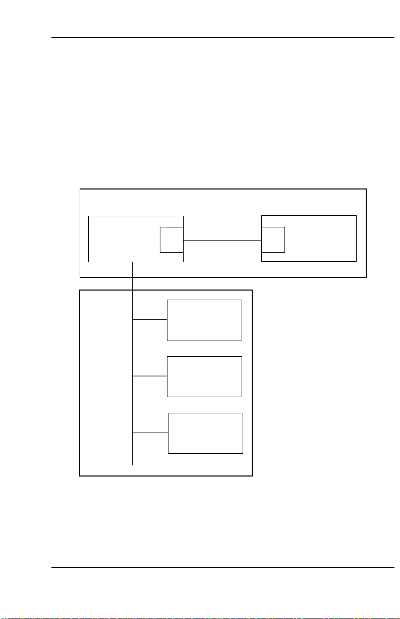
1.2 System configuration
The system configuration is shown in Figure 1-1.
Xi Repro System is to be installed on a computer running Windows NT. When
connected to a copier via a PCI interface cable, a computer running this software
performs as a plotter server. In such a system configuration, this computer is called
the Local Client.
Computers that have this software installed and use the copier connected to the
Local Client are called Remote Clients.
The Local Client also provides Remote Client facilities.
Plotter controller system
Local Client
(Xi Repro System)
Windows NT
Interface
card
PCI interface cable
Remote Client
(Xi Repro System)
Windows NT
Remote Client
(Xi Repro System)
Windows NT
Remote Client
(Xi Repro System)
Windows NT
Interface
relay
PCB
Figure 1-1 System configuration
Digital copier
1-3
Page 9

Overview
1.3 Product components
1.3.1 Supplied products
The following are supplied with the package.
• CD-ROM (1)
• Interface card
• PCI interface cable
• Relay PCB (2, used during installation)
• Relay cable (used during installation)
• Installation manual
1.3.2 CD-ROM
The supplied CD-ROM contains:
• Xi Repro System (the program for plotter controller)
• LittleBear Driver (the driver which communicates between copier and interface
card)
• Installer (program to install Xi Repro System and the LittleBear Driver)
1-4
Page 10

1.3.3 Xi Repro System
Xi Repro System consists of the following four applications:
1. Client
The Client application provides Xi Repro System’s main facilities. Namely:
• Create a new set.
• Scan files into a set.
• Add to or delete from a set TIFF files, HPGL/2 files or other image files.
• Assign pen settings and plotting instructions to each file.
• Change printing order.
• Preview the contents of an image file before printing.
• Assign stamps to be applied to each plot.
• Print the requested number of copies of a file within a set.
• Delete a set.
2. Admin
The Admin application is a system management tool for defining each device
interfacing with Xi Repro System. This application also serves as a report
preparation tool to show system usage.
Overview
3. Stamp
The Stamp application is a tool for creating stamp files. Xi Repro System uses
such stamp files to place stamps onto copies of a plot that are being printed.
4. Server
The Server application is a tool for controlling the plotter/scanner and is installed
only on the Local Client. This application relays print/scan jobs from the Local
Client or print jobs from Remote Clients to the copier.
1-5
Page 11

Overview
1.4 System requirements
The following is the minimum equipment required to use a system with Xi Repro
System:
• Copier
PointSource Xi 3648
• Computer
200 MHz Pentium Pro Processor
Microsoft Windows NT 4.0 (Service Pack 3 must be installed)
2 GB Hard Disk
128 MB RAM
PCI Bus
1-6
Page 12

2.
This section describes the installation procedure.
2.1 Connecting the machines
2.2 Installing Xi Repro System
2.3 Setting the copier
2.4 Checking operation
2.5 Other software
System Installation
Page 13

System Installation
2. System Installation
Figure 2-1 shows the system installation procedure for the Local Client. See
Network Plotting
for the installation procedure for the Remote Client.
Connecting the machines
Installing Xi Repro System
Setting the copier
Checking operation
Figure 2-1 System installation procedure
6.
2-2
Page 14
System Installation
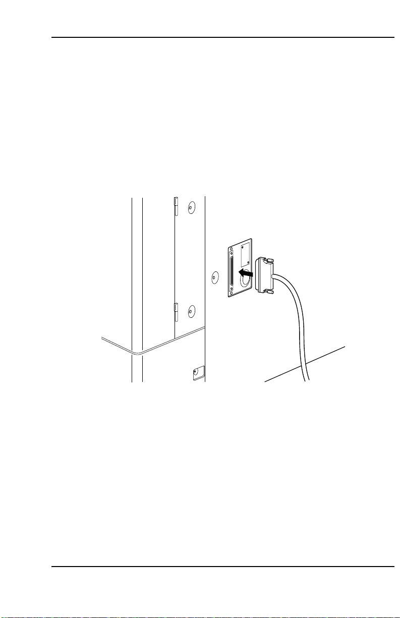
2.1 Connecting the machines
Perform the following steps to install the interface card and connect the machines.
1. Turn the power to both the computer and copier off.
2. Remove the computer cover. Locate an available PCI slot and remove its bracket
and screw.
3. Insert the interface card into the PCI slot by pressing it evenly until it sits correctly
in the slot. Check for correct insertion and secure the card with a screw.
4. Refit the computer cover.
5. Connect the PCI interface cable between the copier and computer.
6. Turn the power to the computer and copier on and then proceed to
Xi Repro System
.
2.2 Installing
2-3
Page 15

System Installation
2.2 Installing Xi Repro System
1. Start Windows NT and close any unnecessary applications.
2. Insert the supplied CD-ROM into the CD-ROM drive.
3. The Setup screen appears followed by the Welcome screen. Click on the “Next”
button.
4. The Choose Destination Location screen appears.
Click on the “Next” button.
5. The Setup Type screen appears.
Select the connected copier and click on the “Next” button.
Select “Client Software” to install Xi Repro System on a Remote Client.
6. The Select Components screen appears.
Select all the components under normal circumstances and click on the “Next”
button.
7. The Select Program Folder screen appears.
Click on the “Next” button.
The program group name can be changed to any desired name.
8. The Start Copying Files screen appears.
Click on the “Next” button.
9. The Setup Complete screen appears after installation is completed.
Remove the CD-ROM from the CD-ROM drive and click on the “Finish” button to
restart the computer automatically.
Proceed to
The installation program creates a program item in the Start menu. The program
group name is “Xi Repro System”, which contains three program items called Client,
Admin and Stamp. The plotter driver is installed in the Windows NT Printers folder at
the same time.
When uninstalling Xi Repro System, files in the C:\Program Files\Xi Repro System\
Plots directory may be deleted. Move any image files before uninstalling Xi Repro
System.
2.3 Setting the copier
.
2-4
Page 16
System Installation
2.3 Setting the copier
Reset the offline status of the copier to use Xi Repro System.
Resetting the offline status of the copier
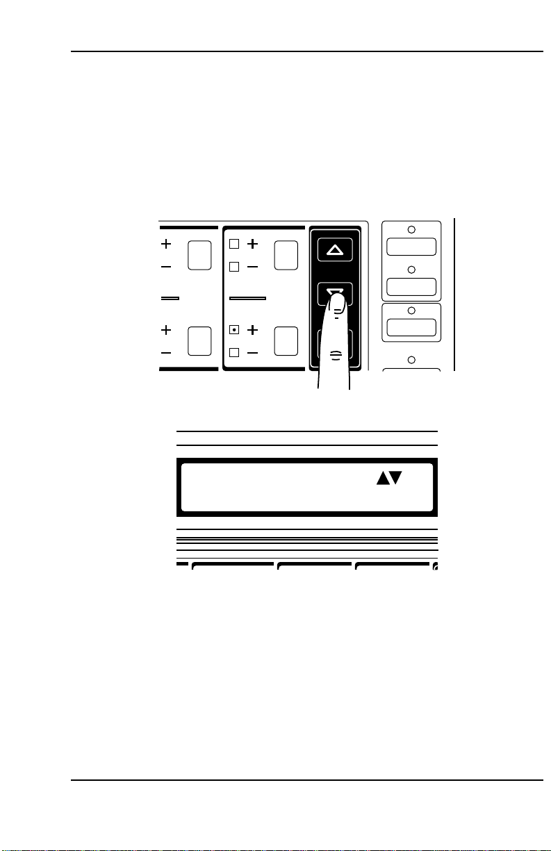
1. Press the added features key on the copier operation panel.
2. Press the mode set keys until the message “10. CONTROLLER MODE” appears.
Interrupt
ding
ling
Edge
Leading
Left
Margin
FUNCTION SETTING
10. CONTROLLER MODE
Enter
Memory
Copy
On-Line
→E
2-5
Page 17
System Installation
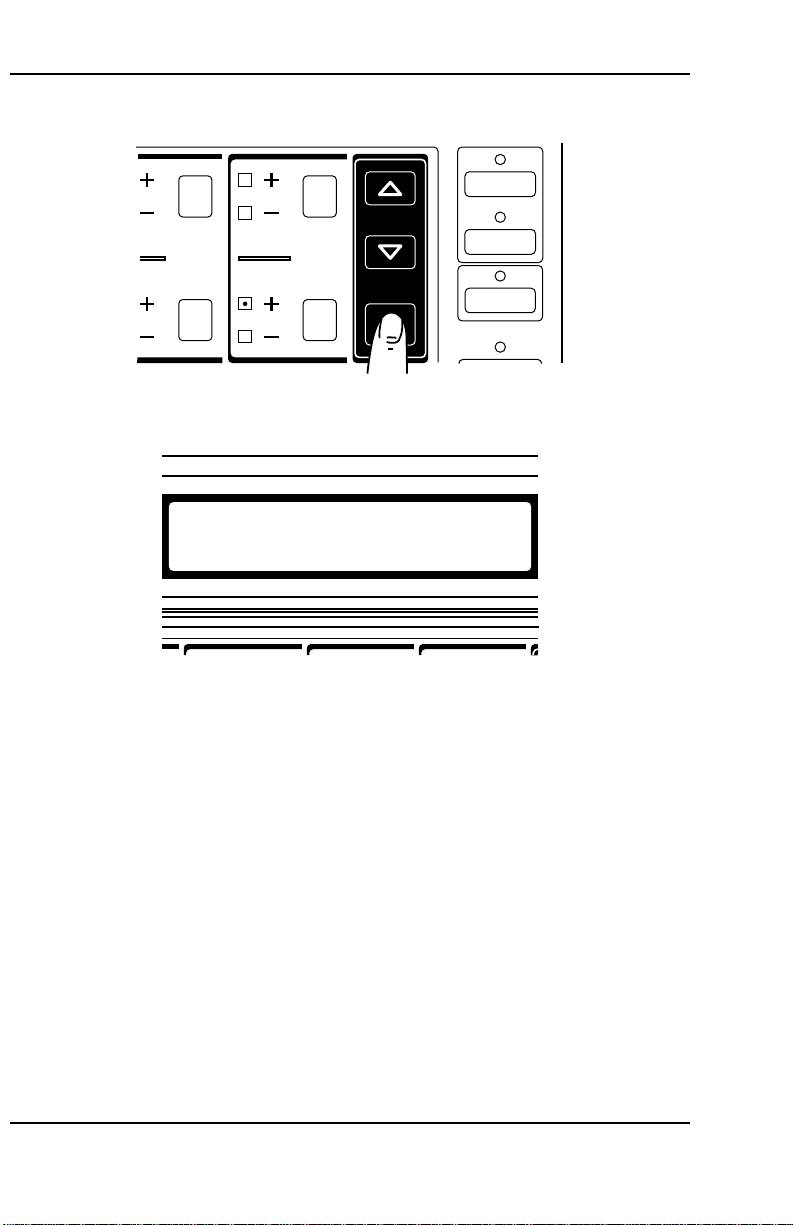
3. Press the enter key.
Interrupt
ding
ling
Edge
Leading
Left
Margin
Enter
Memory
Copy
On-Line
4. Press the mode set keys until the message “2. EXIT OFF LINE” appears.
CONTROLLER MODE
2. EXIT OFF LINE
5. Press the enter key.
6. Press the mode set keys until the message “1. OFF LINE RELEASE” appears.
7. Press the enter key.
The offline status is reset and the on-line indicator on the operation panel turns
on.
8. Press the added features key. The “READY TO COPY” message appears on the
display of the operation panel.
2-6
Page 18

System Installation
The copier cannot be controlled via the copier operation panel while resetting the
offline status. To control the copier via the operation panel, first press the on-line key
to turn the on-line indicator off.
The copier is in the on-line mode (the on-line indicator is on) after the offline status
has been reset. The copier automatically returns to the on-line mode if no copy is
made for a certain period while the copier is offline.
Check the following before starting to control the copier via Xi Repro System or the
copier operation panel.
• Controlling the copier via Xi Repro System
Check if the on-line indicator is on.
If the on-line indicator is off, turn it on by pressing the on-line key.
• Controlling the copier via the copier operation panel
Check if the on-line indicator is off.
If the on-line indicator is on, turn it off by pressing the on-line key.
2-7
Page 19
System Installation
2.4 Checking operation
After the machines are connected, the Xi Repro System is installed and the setting of
the copier is complete, check for correct communication between the computer and
copier by performing the following steps.
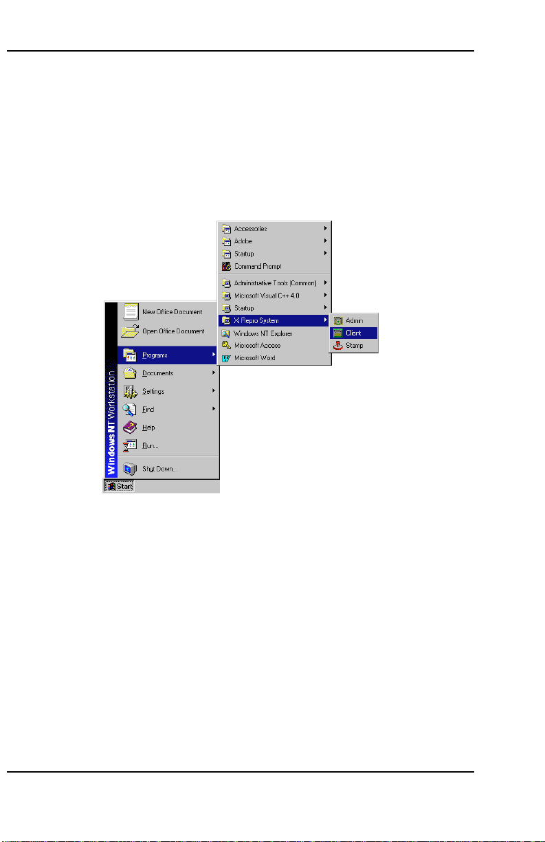
1. Start Windows NT.
2. Open the Start menu by clicking on “Start” in the task bar.
3. Select “Programs” and “Xi Repro System”.
4. Click on “Client”.
The application starts and the project window appears.
2-8
Page 20
System Installation
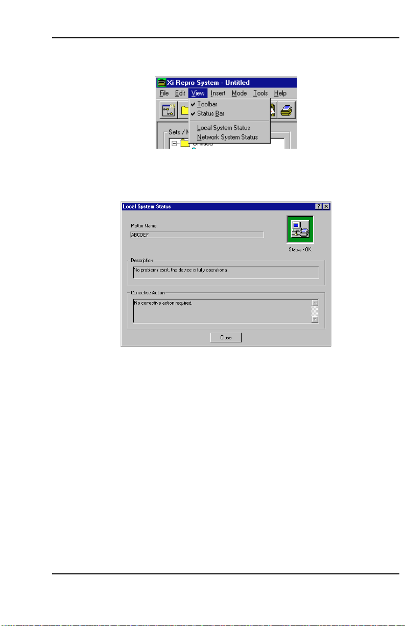
5. Select “Local System Status” from “View” in the menu bar.
6. The Local System Status screen appears. The “Status-OK” message is displayed
at the top right of the screen if communication is good.
7. Click on the “Close” button to close the screen.
Check the following if the “Status-OK” message is not displayed in the Local System
Status screen.
• Is the copier power turned on?
• Is the copier offline status reset?
• Is the copier on-line indicator turned on?
• Are there any error messages on the copier display?
• Is the PCI interface cable connected correctly?
• Is the interface card inserted correctly?
2-9
Page 21

System Installation
2.5 Other software
2.5.1 Virus protection
Since files can frequently be loaded from floppy disks when using Xi Repro System,
installation of a virus protection application is highly recommended.
2.5.2 Image editor
Xi Repro System is capable of displaying images. High resolution images can also be
displayed by specifying the image editor in the option setting of Client.
3.6 Displaying and editing a plot
See
for details.
Notes
To use Xi Repro System on a network, ensure that the Windows NT network is
configured correctly.
To use Xi Repro System locally where no network adapter is installed, configure it as
follows.
1. Open the control panel and click on “Network” to install the network software. If
the network software is already installed, proceed to step 2. Restart Windows NT
after installation.
2. Open the control panel, click on “Network” and select the Adapter tab.
3. Click on the “Add” button and select MS Loopback Adapter. Select Ethernet
802.3 for the frame type.
4. Insert the Windows NT CD-ROM into the CD-ROM drive if requested.
5. Restart the computer.
2-10
Page 22

3.
This section describes how to use Client.
3.1 Starting and closing the application
3.2 Creating and saving a project file
3.3 Sets/members tree
3.4 Creating and deleting a new set
3.5 Inserting and deleting a plot
3.6 Displaying and editing a plot
3.7 Inserting and deleting a stamp
3.8 Editing a stamp
3.9 Inserting and deleting a pen set
3.10 Changing the order of the sets/members tree
3.11 Printing
3.12 Scanning
3.13 Setting properties
3.14 Setting options
3.15 Default settings
Using Client
Page 23
Using Client
3. Using Client
The Local Client and Remote Clients provide the same facilities except that Remote
Clients do not provide a scanner facility.
3.1 Starting and closing the application
3.1.1 Starting the application
Perform the following steps to start the application.
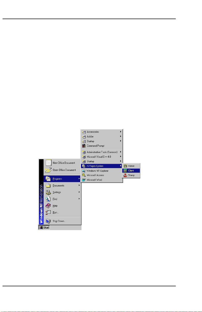
1. Click on “Start” in the task bar to open the start menu.
2. Select “Programs” and then “Xi Repro system”.
3. Click on “Client”.
The application starts and the project window appears.
3-2
Page 24
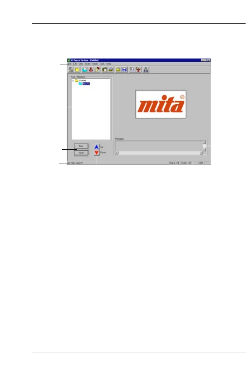
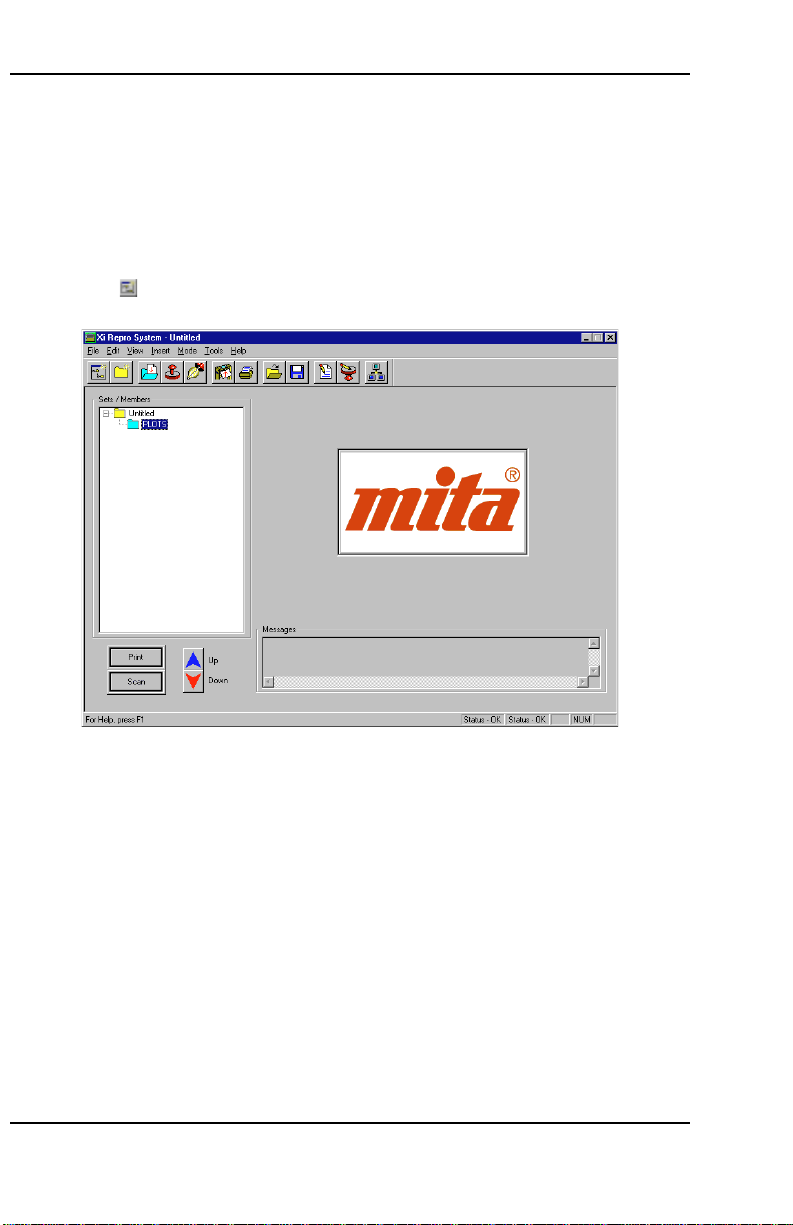
3.1.2 Project window
This section describes the project window displayed when starting Client.
1
2
Using Client
3
4
8
5
1 Menu bar.
2 Toolbar.
3 Sets/members tree of a project.
4 Buttons for printing/scanning.
5 Buttons to change the placement of set members.
6 Box in which a plot thumbnail is displayed.
7 Box in which a message indicating Client activities is displayed.
8 Status bar. Displays information about the menu item indicated by the mouse.
6
7
3-3
Page 25

Using Client
3.1.3 Select the units system
Perform the following steps to select the units system used in the application.
1. Click on “Tools” in the menu bar to open the Tools menu.
2. Click on “Options”.
3. Select the Preferences tab, then the units system to be used in “Units” (see
3.14.2 Preferences tab
).
3-4
Page 26
3.1.4 Closing the application
Perform the following steps to close the application.
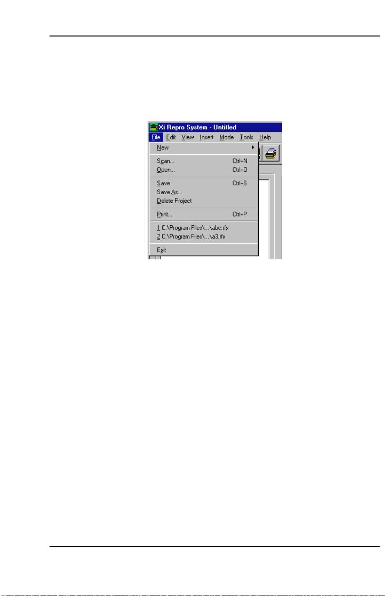
1. Click on “File” in the menu bar to open the File menu.
2. Click on “Exit”.
Using Client
3-5
Page 27
Using Client
3.2 Creating and saving a project file
3.2.1 Creating a new project file
When Client is started, it creates a new project called “Untitled”.
A new project can also be created by either of the following methods:
• Click on “New” and then “Project” from “File” in the menu bar.
• Click on the
button in the toolbar.
3-6
Page 28
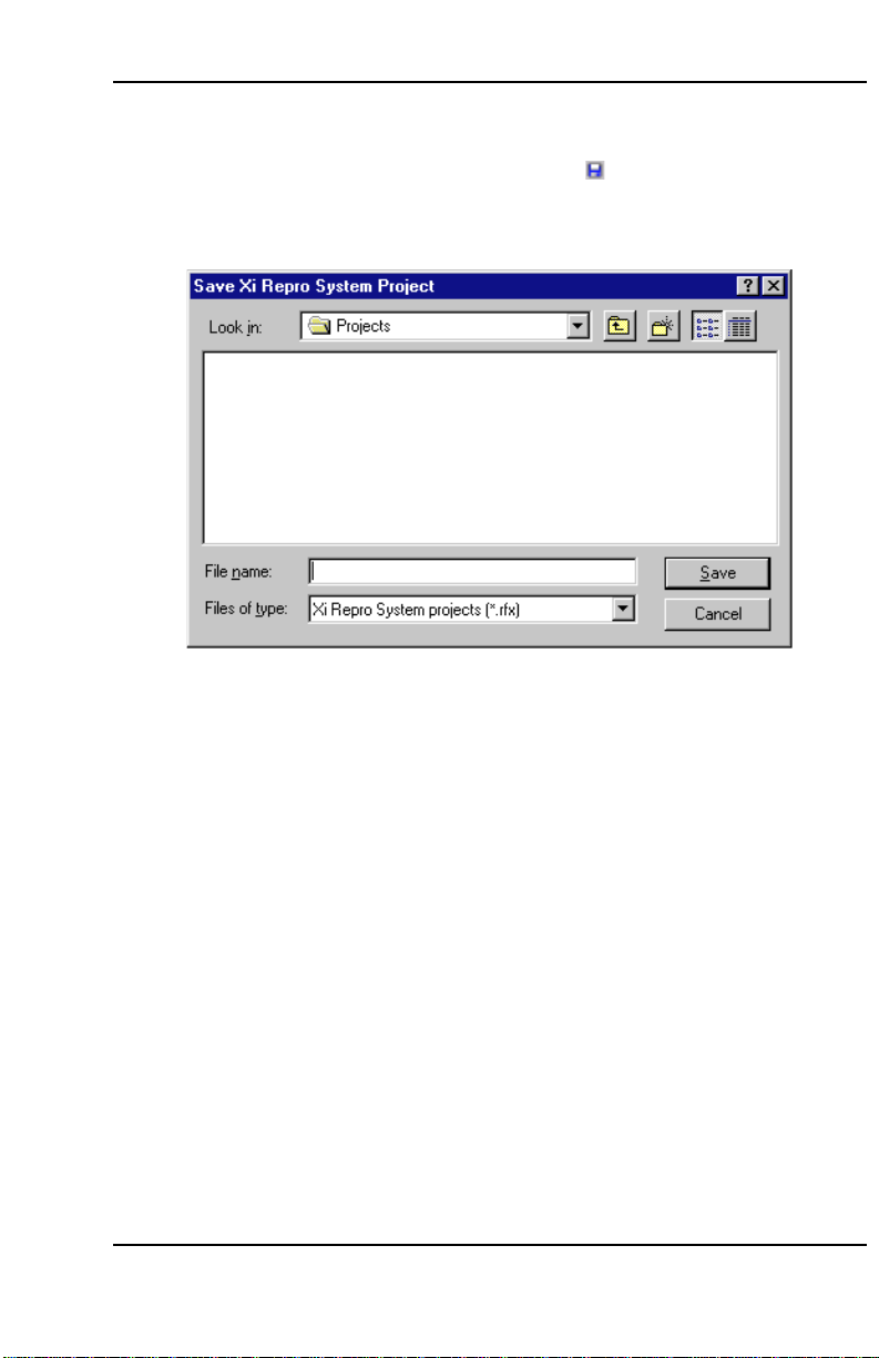
3.2.2 Saving a project file
Using Client
1. Click on “Save” from “File” in the menu bar or the
2. Specify the directory, enter the filename and then click on the “Save” button. A
project is saved as a project file with the “.rfx” extension.
A project file is simply a list of the names of plots added to the sets/members tree; no
images or stamps to be printed are contained in the project file.
in the toolbar.
3-7
Page 29
Using Client
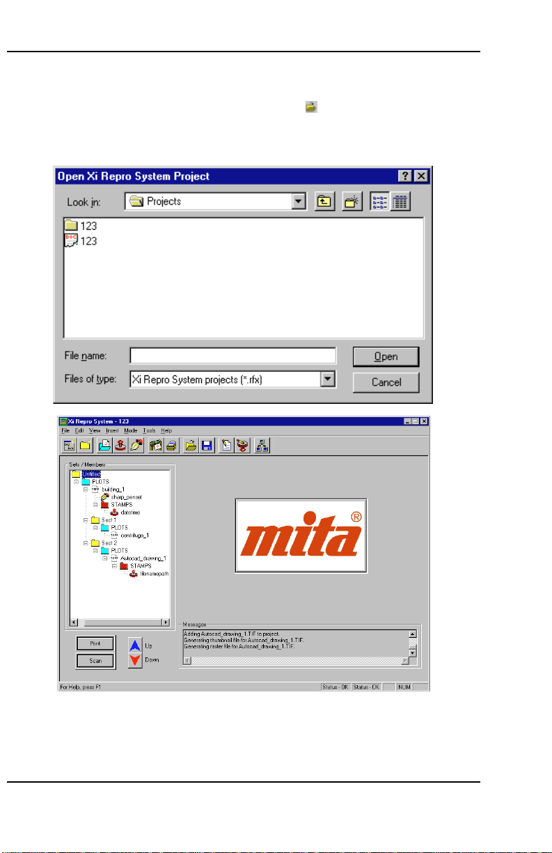
3.2.3 Opening an existing project file
1. Click on “Open” from “File” in the menu bar or the
2. Select the project to be opened and click on the “Open” button. The project
window appears.
button in the toolbar.
3-8
Page 30
Using Client
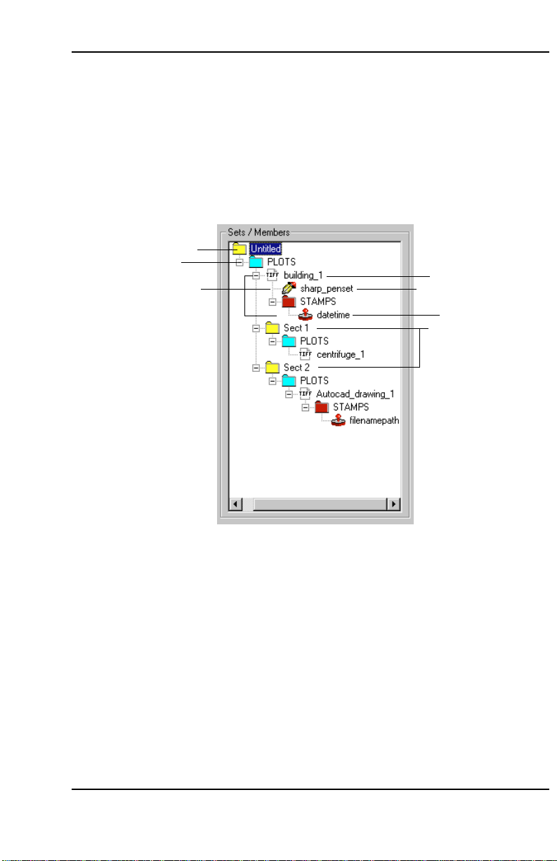
3.3 Sets/members tree
The sets/members tree in the project window shows the project file status visually.
Using Client, printing is enabled by adding an image file to the sets/members tree.
The Client application is used for adding a plot, stamp and pen set to and deleting
them from the sets/members tree and for defining print settings.
The figure below is an example of the sets/members tree to which image files and
other items have been added.
1
2
6
3
4
5
7
3-9
Page 31

Using Client
1 Project
Displays the project filename.
2 Set
One per project.
A project can be compared to a box to which a plot, stamp and pen set are
added. Multiple plots inserted in the set can be printed at one time.
3 Plot
An image file added to the set. Print and other settings can be defined for each of
the inserted plots. Data from scanning a hard copy can also be added as a plot.
See the appendix for a list of the acceptable file formats.
4 Pen set
Used when selecting pens for printing: can be set when a plot is a vector file
format.
5 Stamp
Useful for printing the date and operator names over the plot file image. Since
stamps are stored independently as stamp files, the contents of a stamp can be
modified without affecting a plot.
6 Member
Each of the plots, stamps or pen sets added to a set.
7 Sub-sets
Can be created in a set by dividing multiple plots in a set into groups. The
illustration on the previous page shows an example of sub-sets: two sub-sets
“Sect 1” and “Sect 2” have been added. This is useful when, for example, one
wishes to print only the plots in Sect 2.
3-10
Page 32

Using Client
3.4 Creating and deleting a new set
3.4.1 Creating a new set
To create a new set, select “New” and then “Set” in the File menu or click on the
button in the toolbar. A new set is created as a sub-set of the currently selected set.
3.4.2 Changing a set name
A new set is automatically named “New Set”. To change the name, select the set in
the sets/members tree and click on the name. The new name can then be entered.
3.4.3 Deleting a set
To delete a set, select the set to be deleted and press the delete key. All members
within the set are deleted as well.
3-11
Page 33

Using Client
3.5 Inserting and deleting a plot
3.5.1 Inserting a plot
An existing image file can be inserted as a plot into a set. Scanned image data can
also be inserted as a plot (see
Perform the following steps when inserting an image file as a plot into a set.
1. Select the set where the image is inserted from the sets/members tree.
2. Select “Image” in the Insert menu or click on the
select dialog box is displayed.
3. Select the file to be inserted and click on the “Open” button. Only file formats
accepted by Client can be inserted (see
3.12 Scanning
).
button in the toolbar. The file
9.4 Plot file formats
).
3.5.2 Deleting a plot
To delete a plot, select the file to be deleted and press the delete key.
3-12
Page 34

Using Client
3.6 Displaying and editing a plot
3.6.1 Displaying a plot
When a plot is selected from the sets/members tree, a thumbnail (low resolution
version) of the image is displayed on the right side of the project window. When a plot
is inserted in a set, a thumbnail is automatically created from the plot.
When displaying an image of a higher resolution plot, select the plot to be displayed
from the sets/members tree and select “Image Editor” in the Tools menu or click on
the
button in the toolbar. The image editor is started and the image of the raster
file is displayed. A raster file is a TIFF file created for printing from a source plot file
inserted in the set.
By using the Preferences tab in Options, the point at which a raster file is created can
be selected between when a plot is inserted into a set and when it is printed. It can
also be created easily by using “RIP” in the Names tab in Properties.
3-13
Page 35

Using Client
3.6.2 Editing a source plot file
A source plot file can be edited only when a plot is not saved in a vector format.
Perform the following steps when editing a source plot file.
1. Select the source plot file to be edited from the sets/members tree.
2. Select “Modify” in the Edit menu. The Modify Plot dialog box is displayed.
3. Check the item to be converted in “Transformations”.
Select “Despeckle” to remove small speckles (see
Select “Deskew” to correct a skewed image (see
Select “Invert” to swap white and black.
Select “Mirror” to mirror the plot file.
Select “Scale” to enlarge/reduce an image by 25 to 400%.
4. Define the rotation angle of the image by “Rotate”.
9.2 Technical notes
9.2 Technical notes
).
).
3-14
Page 36

Using Client
5. Select a method to save the edited source plot file.
Select “Modify Source Plot File” to overwrite the original file. Note that the old
data cannot be recovered after the edited data is saved.
Select “Replace Source Plot File” to save the edited data as a new file having a
different name.
Select “Modify Raster File” to save the edited data over the raster file.
6. Click on the “OK” button. When “Modify Source Plot File” is selected in step 4,
the Confirm Plot Modification dialog box is displayed.
7. Check “Re-RIP modified file immediately” to create a raster file of the edited
source plot file immediately.
8. Click on the “OK” button to start editing the source plot file.
3-15
Page 37

Using Client
3.6.3 Editing a raster file
Select the source plot file of the raster file to be edited from the sets/members tree
and then “Image Editor” in the Tools menu or click on the
editor is then started and a raster file image is displayed. Edit the raster file using the
image editor.
A raster file can also be edited by clicking on the “Edit” button in the Names tab of the
Properties (see
The edited raster file can be restored to the original one by clicking on the “RIP”
button in the Names tab of Properties.
3.13.1 Names tab
).
in the toolbar. The image
3-16
Page 38

Using Client
3.7 Inserting and deleting a stamp
3.7.1 Inserting a stamp
The stamp file created by the Stamp application can be inserted into a set or plot. A
stamp inserted into a set can be applied to all the plots in the set. A stamp inserted in
a plot can be applied to that plot only.
Perform the following steps when inserting a stamp.
1. Select the set or plot from the sets/members tree into which a stamp is to be
inserted.
2. Select “Stamp” from the Insert menu or click on the
file select dialog box is displayed.
3. Select the stamp to be inserted and click on the “Open” button.
button in the toolbar. The
3.7.2 Deleting a stamp
To delete a stamp, select the stamp to be deleted and press the delete key.
3-17
Page 39

Using Client
3.8 Editing a stamp
To change the insertion point and characteristics of a stamp in a plot for printing,
select the stamp file to be changed from the sets/members tree and Properties in the
Edit menu. The Stamp tab is then displayed and the setting can be changed (see
3.13.7 Stamp tab).
To edit a stamp, select the stamp file to be edited from the sets/members tree and
select “Stamp Editor” in the Tools menu or click on the
Stamp application is started and the stamp can be edited (see
Stamp editing can also be started by clicking on the “Edit Stamp” button in the Stamp
tab.
button in the toolbar. The
5 Using Stamp
).
3-18
Page 40

Using Client
3.9 Inserting and deleting a pen set
3.9.1 Inserting a pen set
A pen set that is used when a vector plot file is rasterized can be inserted in a set or
plot. A pen set inserted in a set can be applied to all the plots in the set. The pen set
inserted in a plot can be applied only to that plot.
Perform the following steps when inserting a pen set.
1. Select a set or plot from the sets/members tree into which a pen set is to be
inserted.
2. Select “Pen set” from the Insert menu or click on the
file select dialog box is displayed.
3. Select the pen set to be inserted and click on the “Open” button.
button in the toolbar. The
3.9.2 Deleting a pen set
To delete a pen set, select the pen set to be deleted and press the delete key.
3-19
Page 41

Using Client
3.10 Changing the order of the sets/members tree
The printing order can be changed by moving members in a set.
Perform the following steps when moving a member.
1. Select the member to be moved from the sets/members tree.
2. Click on the “Up”/“Down” buttons on the project
can also be moved by selecting “Move Up”/“Move Down” in the Edit menu.
A member can also be moved by drag-and-drop.
window to move the member. It
3-20
Page 42

Using Client
3.11 Printing
3.11.1 Printing
Printing is performed using the rasterized data.
Perform the following steps when printing.
1. When using the setting and plotter for the previous print job, proceed to step 6.
Select “Options” from the Tools menu and then the Accounting tab.
2. Assign the cost center and user ID to record the print job information (see
Accounting tab
).
3.14.1
3-21
Page 43

Using Client
3. Select a set or plot to be printed from the sets/members tree.
4. Select “Print” from the File menu or click on the “Print” button on the project
window or
5. Select the printer in “Destination”.
6. Set the number of copies and copying order in “Copies”.
7. Click on the “Options” button to change the option settings (see 3.14
options
8. Click on the “Start Print” button.
button in the toolbar. The print dialog box is displayed.
Setting
).
3-22
Page 44

Using Client
3.11.2 Print dialog box
• Destination
Used to select one of three printing destinations: a plotter, “Printer” and “E-Mail to”.
“E-Mail to” is not supported in this software version.
The plotter connected to the Local Client is displayed in the plotter box.
The plotter box is not displayed on Remote Clients.
“Printer” displays the printer driver installed in the Windows NT Printers folder.
“E-Mail to” is selected when using a remote printer via e-mail. Enter an e-mail
address to which the print job is sent in the box. When auto-dialing to the remote
access server (RAS), type the location to be dialed in the Phone Book Entry box.
• Files
Displays the file to be printed.
• Copies
Used to set the number of copies.
When checking “Collate”, the set number of copies is printed page by page.
When checking “Reverse”, printing is performed from the last data in the sets/
members tree.
• Media
Displays the media, or paper, to be used.
Use the Media tab in Properties to define the paper to be used (see
tab
).
3.13.3 Media
3-23
Page 45

4.
This section describes how to use Admin.
4.1 Starting and closing the application
4.2 Cost Center tab
4.3 Report tab
4.4 Scanner Sheet Size tab
4.5 About Box Edit tab
4.6 Device Data tab
4.7 Printer tab
4.8 Scanner tab
Using Admin
Page 46

Using Admin
4. Using Admin
The Admin application allows device settings to be configured and system usage
status reports to be viewed. There are seven tabs in the Administrator window. This
chapter describes how to use each of these tabs.
4.1 Starting and closing the application
4.1.1 Starting the application
Perform the following steps to start the application.
1. Click on “Start” in the task bar to open the start menu.
2. Select “Programs” and then “Xi Repro System”.
3. Click on “Admin”.
The application starts and the Administrator window appears.
4-2
Page 47

Using Admin
4.1.2 About the Administrator window
This section describes the Administrator window which appears when the application
starts.
1
2
1 Menu bar. Used when closing the Admin application, changing the units system
used in Admin or viewing Help.
2 Status bar. Displays information about the menu item indicated by the mouse.
4-3
Page 48

Using Admin
4.1.3 Selecting the units system
Perform the following steps to select the units system.
1. Click on “Edit” in the menu bar to open the Edit menu.
2. Click on “Preferences”.
3. Select the units system to be used in “Measurements”.
4-4
Page 49

4.1.4 Closing the application
Perform the following steps to close the application.
1. Click on “File” in the menu bar to open the File menu.
2. Click on “Exit”.
Using Admin
4-5
Page 50

Using Admin
4.2 Cost Center tab
The Cost Center tab displays a list of cost center information. This tab also allows
cost centers to be added, edited or deleted.
Cost centers are used to record the usage status of plotter/scanner devices. The cost
center to be used for recording is specified from the Client application. Only the cost
centers defined under the Cost Center tab will be available for selection in the Client
application.
4-6
Page 51

Using Admin
4.2.1 Adding a cost center
To add a new cost center, click on the “Add” button. This displays the Cost Center
dialog box. Enter in the dialog box the name and description of the cost center, then
click on the “OK” button. A cost center name must have 20 characters or less and a
cost center description must have 80 characters or less.
4.2.2 Editing a cost center
Select the cost center to be edited from the list of cost centers and click on the “Edit”
button. The Cost Center dialog box is displayed. Edit the cost center and click on the
“OK” button.
4.2.3 Deleting a cost center
Select the cost center to be deleted from the list of cost centers and click on the
“Delete” button.
4-7
Page 52

Using Admin
4.3 Report tab
The Report tab displays a report on the selected plotter device, cost center and userID. A text editor is used to display the report.
• Plotter Device
Select the plotter device whose usage status is to be reported.
• Cost Center
Select the cost center whose usage status record is to be reported. Cost centers
available for selection are defined under the Cost Center tab.
• User-ID
Select the user-ID whose usage status is to be reported. User-IDs available for
selection are defined under the Accounting tab in the Options menu of the Client
application.
4-8
Page 53

Using Admin
• Plot Count
The number of print jobs in the database record. The database records the number
of print jobs executed during the period defined by Database Parameters.
• Report Type
Select on of three types.
• Date Range
Define the period to be covered by the system usage status report within the period
defined by Database Parameters.
Click on the “Start Date” button to enter the starting date.
Click on the “End Date” button to enter the end date.
• Report Viewer
The text editor program to be used for viewing the report. The text editor can be
selected by clicking on the “Browse” button.
• Database Parameters
Clicking on this button displays the Database Parameters dialog box. Specify the
directory containing the database to record report information and the period for
which it is retained. The directory containing the database can be specified by
clicking on the “Browse” button. The retaining period may be 30 days, 60 days, 120
days, 6 months, 12 months or indefinite. The record is automatically purged after
this period.
• Run Report
Clicking on this button starts the designated text editor program and displays the
report.
4-9
Page 54

Using Admin
4.4 Scanner Sheet Size tab
This tab displays information on the available scanning area size options (called
“scanner sheet sizes”). This tab also allows scanner sheet sizes to be added, edited
or deleted.
The sheet names defined under this tab are used in the Scan dialog of the Client
application.
• Sheet Name
The sheet name that identifies the scanner sheet size.
• Width
The width of the scanner sheet size.
• Height
The height of the scanner sheet size.
4-10
Page 55

Using Admin
4.4.1 Adding a scanner sheet size
To add a new scanner sheet size, click on “Add Sheet Size”. The Scanner Sheet Size
dialog box appears. Define the scanner sheet name and scanner sheet size
parameters, then click on “OK”.
• A Sheet Name may have up to 25 characters.
• X (width) may be set to any value between 1.000000" and 36.000000".
• Y (height) may be set to any value between 1.000000" and 392.913333".
4.4.2 Editing a scanner sheet size
Select the scanner sheet size to be edited from the scanner sheet size list and click
on “Edit Sheet Size”. The Edit Sheet Size dialog box appears. Edit in the dialog box,
then click on “OK”.
4.4.3 Deleting a scanner sheet size
Select the scanner sheet size to be deleted from the scanner sheet size list and click
on “Delete Sheet Size”.
4-11
Page 56

Using Admin
4.5 About Box Edit tab
This tab allows creation and editing of the text displayed when “About” is selected
from the Help menu of the Admin, Client or Stamp applications.
The text created or edited under this tab is saved in the database by clicking on the
“Save About Box Info” button.
4-12
Page 57

Using Admin
4.6 Device Data tab
The Device Data tab displays information about the plotter/scanner devices used with
Xi Repro System. It also allows devices to be edited.
• Device ID
Displays the Device IDs to identify the devices. These IDs are also displayed under
the Printer tab and Scanner tab.
• Device Name
Displays the model names of the devices.
• OpMode
Indicates whether a device is to be used only as a printer, only as a scanner or as
both. The code “1” means it is used only as a printer, “2” means only as a scanner
and “3” means it is used both as a printer and scanner.
• Enabled
Indicates whether the device is available for use by Client. The code “1” means it is
available (enabled) and “0” means not available (disabled).
• Controller
Indicates whether an interface card is used. The code “1” means an interface card
is used and “0” means not used.
4-13
Page 58

Using Admin
4.6.1 Editing a device
Select the device to be edited from the device list and click on the “Edit Device”
button. The Device dialog box appears. Edit the device in the box, then click on the
“OK” button.
The Name and Enabled boxes are available in this software version. In other
versions, they are unavailable and displayed only.
• A Device ID may be set to 6, 7 or 8.
• A Name may have up to 20 characters.
• Select a Device Mode from the drop-down list box.
• Check “Enabled” when using the device from Client.
• Check “Controller” if an interface card is used.
4-14
Page 59

Using Admin
4.7 Printer tab
The Printer tab displays a list of printers and printer modes.
Printers
• Device ID
Lists the device IDs of all devices that have been defined as printers. The Device
IDs displayed here are the same as the Device IDs defined under the Device Data
tab.
• Resolution
Shows the printer resolution in dots per inch (dpi).
• Drawers
Shows how many paper drawers each printer has.
• Print Settings
Shows print density.
4-15
Page 60

Using Admin
• Manual Feed
Shows if manual feed is enabled; “1” when enabled or “0” when disabled.
• Detects Media
Shows if automatic paper type detection is enabled; “1” when enabled or “0” when
disabled.
• Detects Width
Shows if automatic paper width detection is enabled; “1” when enabled or “0” when
disabled.
• Auto Rollover
Shows whether the printer automatically switches over to a new paper roll when it
has run out of paper. Shows “1” when Auto Rollover is enabled or “0” when
disabled.
• Min Scale Factor
Shows the minimum scale factor available for printing.
• Max Scale Factor
Shows the maximum scale factor available for printing.
• Drivers
Shows the name of the driver used for the printer interface card.
Printer Modes
• Device ID
Lists the device IDs of the printers.
• Mode Name
A name representing the printer operation mode.
• Mode ID
An ID that identifies the printer mode.
4-16
Page 61

Using Admin
4.8 Scanner tab
The Scanner tab displays a list of scanners and scanner modes.
Scanners
• Device ID
Lists the device IDs of all devices that have been defined as a scanner. The Device
ID displayed here is the same as the Device ID defined under the Device Data tab.
• Resolution
Shows the scanning resolution in dots per inch (dpi).
• Scan Settings
Shows scanning density.
• Auto Length/Width
Indicates if the automatic detection of scanning area length/width is enabled; “1”
when enabled or “0” when disabled.
4-17
Page 62

Using Admin
• Specify Width
Indicates if the width of the scanning area can be specified from the Client
application; “1” when it is enabled or “0” when disabled.
• Fixed Sizes
Indicates if the size of the scanning area can be specified from the Client
application; “1” when it is enabled or “0” when disabled.
• Auto Exposure
Indicates if automatic exposure is enabled; “1” when enabled or “0” when disabled.
• Min Scale Factor
Shows the minimum scale factor available for scanning.
• Max Scale Factor
Shows the maximum scale factor available for scanning.
• Drivers
Shows the name of the driver used for the scanner interface card.
Scan Modes
• Device ID
Lists the device IDs of the scannres.
• Mode Name
A name representing the scanning operation mode.
• Mode ID
An ID that identifies the scanning mode.
4-18
Page 63

5.
This section describes how to use Stamp.
5.1 Starting and closing the application
5.2 Creating and saving a stamp
5.3 Editing a stamp
5.4 Checking the stamp
Using Stamp
Page 64

Using Stamp
5. Using Stamp
5.1 Starting and closing the application
5.1.1 Starting the application
Perform the following steps to start the application.
1. Click on “Start” in the task bar to open the Start menu.
2. Select “Programs” and then “Xi Repro System”.
3. Click on “Stamp”.
The application starts and the Text Stamp Editor window appears.
5-2
Page 65

5.1.2 Text Stamp Editor window
The Text Stamp Editor window is described in this section.
1
2
3
4
5
Using Stamp
6
7
9
0
1 Menu bar.
2 Toolbar.
3 Font selection bar.
4 Edit Text box.
5 Insert Parameters box.
6 Preview box.
7 Sets the rotation angle of a character.
8 Sets the rotation angle of the entire text.
9 Comment box.
0 Status bar. Displays information about the menu item indicated by the mouse.
8
5-3
Page 66

Using Stamp
5.1.3 Closing the application
Perform the following steps to close the application.
1. Click on “File” in the menu bar to open the File menu.
2. Click on “Exit”.
5-4
Page 67

5.2 Creating and saving a stamp
5.2.1 Creating a new stamp
When Stamp is started, it creates a new stamp called “Untitled”.
A new stamp can also be created by either of the following methods:
• Click on “New” from “File” in the menu bar.
Using Stamp
• Click on the
button in the toolbar.
5-5
Page 68

Using Stamp
5.2.2 Saving a stamp
1. Click on “Save” from “File” in the menu bar or the
2. Specify the directory, enter the filename and then click on the “Save” button. A
stamp is saved as a stamp file with the “.stp” extension.
button in the toolbar.
5-6
Page 69

5.2.3 Opening an existing stamp
Using Stamp
1. Click on “Open” from “File” in the menu bar or the
2. Select the stamp to be opened and click on the “Open” button. The Text Stamp
Editor window appears.
button in the toolbar.
5-7
Page 70

Using Stamp
5.3 Editing a stamp
5.3.1 Editing text
Type or edit the text in the Edit Text box to insert it as a stamp. Click the mouse at the
desired position and type the text.
Right clicking in the Edit Text box shows the edit menu enabling cutting, pasting or
copying of the text.
When parameters are inserted into a stamp, the Edit Text box shows “$xxxx”. The
character string indicating the parameter cannot be edited.
5-8
Page 71

Using Stamp
5.3.2 Inserting a parameter
Click on the desired parameter in the drop-down list box of the Insert Parameters box
and then click on the “Insert Parameters” button. The parameters listed in Table 5-1
can be inserted.
Parameters are inserted at the cursor location in the Edit Text box.
Table 5-1 Types of parameters
Parameter Description
$ModificationDate The date when the file was modified
$ModificationTime The time when the file was modified
$CurrentDate The date when the plot file was printed
$CurrentTime The time when the plot file was printed
$Filename The name of the original file
$FilePathName The name of the file path
$MemberName The member name of the file
$CostCenter A cost center that records printing and
scanning jobs
$Description The description of the Cost Center
$SheetNumber Printing order for continuous printing
$TotalSheetNumber Total number of sheets in continuous printing
5-9
Page 72

Using Stamp
5.3.3 Changing the font
Change the font in the font selection bar.
1
1 Font selection drop-down list box
The fonts registered in the computer are available.
2 Font size drop-down list box
The font size can be selected from the fixed sizes (between 8 and 72 points) or
specified by typing a number (between 1 and 1638 points).
5.3.4 Changing the letter style
Change the style by using “Format” in the menu bar or the buttons on the font
selection bar.
Bold
Boldfaces the text.
Italic
Italicizes the text.
Underline
Underlines the text.
2
5-10
Align Left
Centered
Align Right
Page 73

Using Stamp
5.3.5 Rotation
Character rotation
Rotates a character to the specified angle. The character can be rotated
anticlockwise to any angle between 0 and 360 degrees. Specify the angle by clicking
on or or typing a number.
Base rotation
Rotates the entire text to the specified angle. The line can be rotated anticlockwise to
any angle between 0 and 360 degrees pivoting around the top left corner of the text.
Specify the angle by clicking on
or or typing a number.
5-11
Page 74

Using Stamp
5.4 Checking the stamp
Check the printing status of the edited stamp in the Preview box.
5-12
Page 75

6.
This section describes plotter setting for network use.
6.1 Setting the Remote Client
6.2 Setting the Local Client
6.3 Checking Remote Client operation
6.4 Returning to local mode
Network Plotting
Page 76

Network Plotting
6. Network Plotting
In this section, for convenience the Client application running on the Local Client is
called the Local Client application and the Client application running on a Remote
Client the Remote Client application.
The Local Client application operates in two modes: local mode and network mode.
In local mode, the Local Client can use the connected plotter/scanner to both print
and scan. In network mode, the Local Client serves as a plotter server to receive print
jobs from other network Clients, namely Remote Clients, and prints them on the
connected plotter.
In the network mode, the Local Client application provides plotter server facilities
only.
Even though the Local Client application is closed in the network mode, it still serves
as a plotter server. However, no Print Problem messages (indicating print errors) are
displayed. When a print error occurs, restart the Client application and then solve the
problem.
For information on how to operate on the Remote Client,
Using Admin
and
5. Using Stamp
.
see
3. Using Client, 4.
6-2
Page 77

Network Plotting
6.1 Setting the Remote Client
6.1.1 Installing Xi Repro System
Install Xi Repro System on a Remote Client as follows:
1. Start Windows NT and close any unnecessary applications.
2. Insert the supplied CD-ROM into the CD-ROM drive.
3. The Setup screen appears followed by the Welcome screen. Click on the “Next”
button.
4. The Choose Destination Location screen appears.
Click on the “Next” button.
5. The Setup Type screen appears.
Select “Client Software” and click on the “Next” button.
6. The Select Components screen appears.
Select all the components for normal operation and click on the “Next” button.
7. The Select Program Folder screen appears.
Click on the “Next” button.
The program group name can be changed to another name if so desired.
8. The Start Copying Files screen appears.
Click on the “Next” button.
9. The Setup Complete screen appears after installation is complete.
Remove the CD-ROM from the CD-ROM drive and click on the “Finish” button to
automatically restart the computer.
The installation program creates a program item in the Start menu. The program
group name is “Xi Repro System”. It contains three program items, called Client,
Admin and Stamp.
On uninstalling Xi Repro System, files in the C:\Program Files\Xi Repro System
directory may be deleted. Move any image files before uninstalling Xi Repro System.
6-3
Page 78

Network Plotting
6.1.2 Setting the printer
To use the plotter on the network at a Remote Client, printer configuration must be
performed.
Configure the printer as follows:
1. Click “Start” in the task bar to open the Start menu.
2. Click “Printers” in “Settings”.
3. Double-click “Add Printer”.
6-4
Page 79

Network Plotting
4. Select “Network printer server” and click “Next”.
5. The Connect to Printer dialog box opens. Select the plotter connected to the
server and click “OK”.
6-5
Page 80

Network Plotting
6. Select whether to configure the plotter as the default printer and click “Next”.
7. Click “Finish”.
8. An icon for the configured plotter appears in the Printers folder.
6-6
Page 81

Network Plotting
6.2 Setting the Local Client
To use the Local Client as the plotter server, the Local Client must be in the network
mode.
To enter network mode, perform the following steps.
1. Start the Local Client application.
2. Select “Network” from the Mode menu or click on the
mode dialog is displayed at the right of the project window.
button. The network
6-7
Page 82

Network Plotting
6.3 Checking Remote Client operation
Check for correct communication between a Remote Client and the plotter server by
performing the following steps after making the Remote Client and Local Client
settings.
1. Start Windows NT.
2. Open the Start menu by clicking on “Start” in the task bar.
3. Select “Programs” and “Xi Repro System”.
4. Click on “Client”. The Remote Client application starts and the project window
appears.
6-8
Page 83

Network Plotting
5. Select “Network System Status” in the View menu.
6. The Network System Status screen appears. If communication is good, the “StatusOK” message is displayed at the top right of the screen.
7. Click on the “Close” button to close the screen.
If the “Status-OK” message is not displayed in the Network System Status screen,
check whether the designated printer and the plotter server are configured correctly
(see
2.4 Checking operation
).
6-9
Page 84

Network Plotting
6.4 Returning to local mode
In network mode, the Local Client application only provides plotter server facilities. In
order to use other Client facilities, it is necessary to return to local mode.
There are three ways to return to local mode:
“Immediately”: Click on this button to return to local mode, even in the middle of the
current plot.
“After Current Plot”: Click on this button to return to local mode after the current plot.
Even if there are other plots remaining in the print job, only the current plot will be
printed.
“After Current Job”: Click on this button to return to local mode after the current job.
All the plots in the print job will be printed.
6-10
Page 85

7.
This section describes troubleshooting procedures.
7.1 Troubleshooting
Troubleshooting
Page 86

Troubleshooting
7. Troubleshooting
7.1 Troubleshooting
Trouble Check procedure/corrective measures
Xi Repro System cannot
be operated.
The copier cannot be
controlled via the copier
operation panel.
Printing from Xi Repro
System is disabled.
Tail of the scanned
image is not printed.
Check if the copier power is turned on.
Check if the copier is offline. If it is, reset
it.
Check if the on-line indicator of the copier
is on. If not, turn it on by pressing the online key.
Check if the machines are connected
correctly.
Check if the on-line indicator of the copier
is on. If it is, turn it off by pressing the online key.
If the Print Problems dialog box is displayed, follow the instructions to remove
the cause.
Check if the Windows NT network is configured correctly.
Check “Long Plot” when scanning originals 72" or longer.
Reference
page
2-5
2-7
2-3
2-7
3-27
7-2
Page 87

8.
This section describes the specifications of Xi Repro System.
8.1 Basic specifications
8.2 Hardware specifications
8.3 Software specifications
8.4 Interface specifications
Specifications
Page 88

Specifications
8. Specifications
8.1 Basic specifications
Item Specifications Remarks
Product name
Functions
Attachment
method
System
requirements
Applications
Image
processing
size
Model
CPU
Memory
Hard disk
OS
Scanner input
Printer output
Xi Repro System
Rasterizes and prints the image file
(plot file) specified in Client.
By connecting the PCI controller in-
terface card in the computer and the
video terminal on the relay PCB in
the copier with the interface cable.
IBM PC/AT compatible and PCI
controller interface card
Pentium Pro 200 MHz or faster
128 MB
2 GB or more
Windows NT 4.0 and Service Pack 3
CAD/graphics software that can
store files in HPGL, HPGL/2, TIFF,
Calcomp, BMP and WMF formats
is required to create plot files.
Width: 1.00" – 36.00"
Length: 1.00" – 392.91"
Width: 1.00" – 36.00"
Length: 1.00" – 392.91"
The relay PCB
shall be
installed by a
serviceperson.
8-2
Page 89

Resolution
File formats
System units
Application
configurations
Operating
environment
Specifications
Item Specifications Remarks
Scanning
Printing
Source plot file
Raster file
Client
Admin
Stamp
Server
Temperature
Humidity
Illumination
intensity
400 × 400 dpi
400 × 400 dpi
HPGL, HPGL/2, TIFF, Calcomp,
BMP and WMF
TIFF
Inches, feet, mm, cm and m are
available.
Setting values are converted to the
corresponding values in other units
based on the inch sizes.
Core application containing plot file
print setting and scan functions.
An application that registers and
edits the values set by Client and
administers the printing and
scanning job history.
An application that creates stamp
files that can be inserted into plot
files.
An application that controls the
plotter/scanner.
10°C/50°F – 35°C/95°F
15 – 85%RH
Less than 3000 lux
Client: Speci-
fied in the Preferences tab
Admin: Specified by “Preferences” in the
menu bar
Installed on the
Local Client
only
8-3
Page 90

Specifications
8.2 Hardware specifications
Item Specifications Remarks
PCI controller
interface card
Rated
Voltage
PCI card
5 V DC ± 5%
Current
Power
consumption
Less than 0.85 A
Depends on the computer power
source.
8-4
Page 91

8.3 Software specifications
8.3.1 Printing
Item Specifications Remarks
Printable file
formats
Sizes
Printing
quantity
Printing order
Printing magnifications
Paper source
setting
Media type
Automatic roll
exchange
Printing
position
Reference
Longitudinal
direction
Lateral
direction
TIFF, HPGL, HPGL/2, Calcomp,
BMP and WMF
Width: 1.00" – 36.00"
Length: 1.00" – 392.91"
1 – 99
Sorting order and reverse order
available
25 – 400%
Without optional drawer: 2 drawers
and bypass
With optional drawer: 3 drawers
and bypass
Paper, vellum and film
Available
Selected between 9 areas (3 long ×
3 wide)
Offset from leading or trailing edge:
0.00" – 36.00"
Offset from right or left edge:
0.00" – 36.00"
Specifications
8-5
Page 92

Specifications
8.3.2 Scanning (Local Client only)
Item Specifications Remarks
Sizes
Length
specification
Scanning
density
Continuous
scanning
Scanning
magnifications
Mirror
Invert
Rotation
Image display
Data saving
format
Width: 1.00" – 36.00"
Length: 1.00" – 392.91"
Set when using originals 72" or
longer
13 steps
Available
25 – 400%
Setting available
Setting available
0°, 90°, 180° and 270°
Thumbnail view after scanning
TIFF
Not available
when specifying the names
of scan files.
8-6
Page 93

8.3.3 Stamping
Item Specifications Remarks
Stamping
angle
Stamping
magnification
Transparency
Border line
Stamping
position
Reference
Specifications
0° – 360°
25 – 2000%
0 – 100% (0.1% increments)
Setting available
Selected between 9 areas (3 long ×
3 wide)
Longitudinal
direction
Lateral
direction
Offset from the leading or trailing
edge: –36.00" – +36.00"
Offset from the right or left edge:
–36.00" – +36.00"
8-7
Page 94

Specifications
8.4 Interface specifications
Item Specifications Remarks
PCI controller
interface card
Video
terminal
Interface
cable
Interface
cable
connector
Installed in a PCI slot of a computer
Installed on the back of the copier
by connecting the internal copier
relay cable to the relay PCB
118", shielded
Interface card: Video 80-pin
Copier: Video 100-pin
The relay PCB
and internal
copier relay
cable shall be
installed by a
serviceperson.
8-8
Page 95

9.
Useful information is listed in this section.
9.1 The LittleBear driver
9.2 Technical notes
9.3 Pen patterns
9.4 Plot file formats
Appendices
Page 96

Appendices
9. Appendices
9.1 The LittleBear driver
Xi Repro System is designed to communicate with the copier through an interface
card. This card is designed specially for communication with digital copiers.
When using the Windows NT operating system to communicate with a copier through
an interface card, a device driver application (the LittleBear driver) must be loaded
onto the computer beforehand. This device driver works as the mediator between the
higher level software (Xi Repro System) and the hardware (interface card). Xi Repro
System never talks directly to the interface card. All signals are relayed through the
LittleBear driver running as part of the operating system.
The LittleBear driver (LittleBear.sys) should be installed in the WinNT\System32\drivers
directory. The LittleBear driver is automatically installed by the installation program.
To check if the LittleBear driver is running, select “Devices” from the Windows NT
control panel.
9-2
Page 97

Appendices
9.2 Technical notes
Deskew
The Deskew function used in the Modify Plot screen automatically corrects skewed
plot images. There is no need to tag two points along a line on an image: the deskew
function automatically detects the angle of the document and rotates it so that it is
straight. An image can be deskewed more than once.
For more control over deskewing an image, any suitable third-party raster editor may
be used.
Despeckle
The Despeckle function used in the Modify Plot and Properties screens is used to help
reduce noise in 1-bit images. Single pixels and pixel spurs on letters and graphics
are removed while leaving the solid areas intact. The despeckle operation performs a
3 × 3 median filter on the image. For each 3 × 3 neighborhood of pixels in the original
image, a single pixel is produced in the output image. In this case the output is the
median of the 9 values in the 3 × 3 neighborhood.
Selecting Despeckle in the Modify Plot screen causes Xi Repro System to replace the
original file with the despeckled version of the file. An image can be despeckled more
than once.
Selecting Despeckle in the Properties screen causes Xi Repro System to generate a
temporary despeckled copy of the image and the temporary copy is printed during
the current print job. The original image is not replaced.
For more control over despeckling an image, any suitable third-party raster editor
may be used.
9-3
Page 98

Appendices
9.3 Pen patterns
Figure 9-1 shows the pen patterns that are used by Xi Repro System when
rasterizing HPGL/2 plot files. The patterns are defined in the patterns.dat file as
16 × 16 pixel blocks. The pattern file can be modified to add additional patterns.
In general, patterns 0 through 15 are designed to be used for line work. Patterns 16
through 29 are designed for filled areas. Patterns 30 and 31 are special dotted line
patterns.
The lines shown in this manual may not accurately represent what Xi Repro System
will produce on a copier.
9-4
Page 99

Appendices
10
11
12
13
14
15
16
17
18
19
20
21
22
23
24
25
26
27
28
29
30
31
0
1
2
3
4
5
6
7
8
9
Figure 9-1 Pen patterns
9-5
Page 100

Appendices
9.4 Plot file formats
The following is a list of file formats accepted for plotting by Xi Repro System.
Only monochrome images (1 bit per pixel) can be printed.
BMP (BMP)
Calcomp
HPGL (HP, HPGL, PLT)
HPGL/2 (HP, HPGL, PLT)
TIFF (TIF)
Windows Metafile (WMF)
9-6
 Loading...