

Page 1
SO-30
Service and
Maintenance
Manual
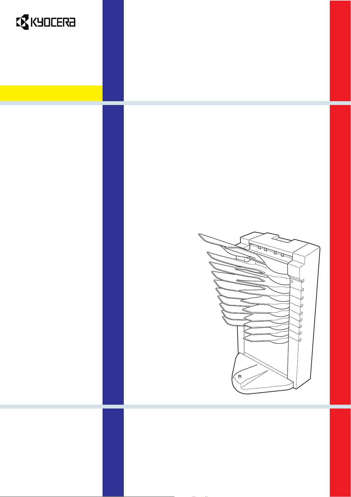
Mailbox/sorter
for
Ecosys printers
SO-30
Page 2

Notices
Mailbox/sorter SO-30 Service Manual ©Kyocera Corporation 1998 All rights reserved. Export Edition
Notices
The information in this manual is subject to change without notification. Additional pages may be inserted in future editions. The user is asked to excuse any
technical inaccuracies or typographical errors in the present edition.
No responsibility is assumed if accidents occur while the user is following the
instructions in this manual. No responsibility is assumed for defects in the product's firmware.
The contents of this manual are protected by copyright. No part of this manual
may be reproduced or copied by any means without the permission of the copyright holder. The product's firmware (contents of its read-only memory) is similarly protected by copyright.
Trademark Notice
Prescribe is a registered trademark of Kyocera Corporation. Prescribe IIe, KIR,
Kyocera Image Refinement, Ecosys, and Ecotone are trademarks of Kyocera Corpo-
ration.
Warning
This equipment has been certified to comply with the limits for a Class B computing device, pursuant to Subpart J of Part 15 of FCC Rules. Only peripherals (computer input/output devices, terminals, etc.) certified to comply with the Class B
limits may be attached to this equipment. Operation with non-certified peripherals is likely to result in interference to radio and TV reception.
Conventions
Throughout this manual, the following conventions are used:
Color is available when viewed online to emphasize important notices.
CAPITAL letters are used to name parts and assemblies.
Italic letters refer related chapters or sections or documentations.
Bold letters are also used for emphasis wherever italics may cause a confuse.
This symbol followed by
graph(s) includes precautions which, if ignored, could result in personal injury,
and/or irrevocable damage to the equipment.
When followed by
include the precautions which, if ignored, could result in damage to the equipment.
Caution
Warning
this symbol denotes that the following paragraph(s)
denotes that the following para-
SO-30
ii
Page 3
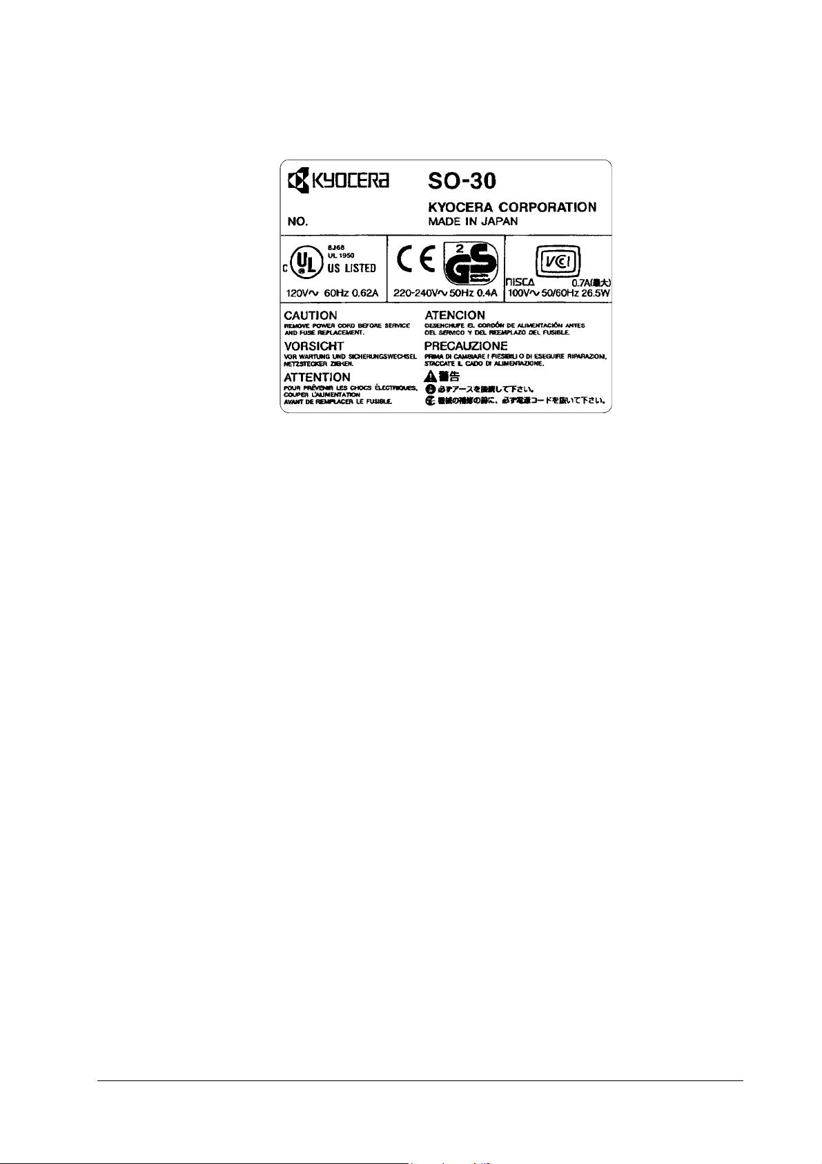
Identification
Identification
iii
SO-30
Page 4

Identification
REVISION HISTORY
Version Date Replaced Pages Remarks
1.0 1-Sep-98 —
VISIT US AT OUR INTERNET HOME PAGE (JAPAN):
FOR AVAILABILITY OF PRINTER DRIVERS AND UTILITIES, ACCESS TO YOUR LOCAL KYOCERA INTERNET SITE.
http://www.kyocera.co.jp
SO-30
iv
Page 5

Chapter 1 PRODUCT INFORMATION
Contents
Part Names 1-2
Mechanical Section 1-3
Electrical Parts 1-4
Connector Layout 1-5
Page 6
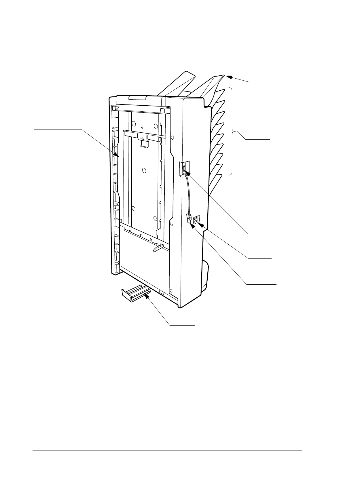
1.1 Part Names
Vertical Transport Unit
Multi Tray
Mail Trays
Slide Rail
Interface Connector
Power Jack
Ground Wire
SO-30
1-2
Page 7
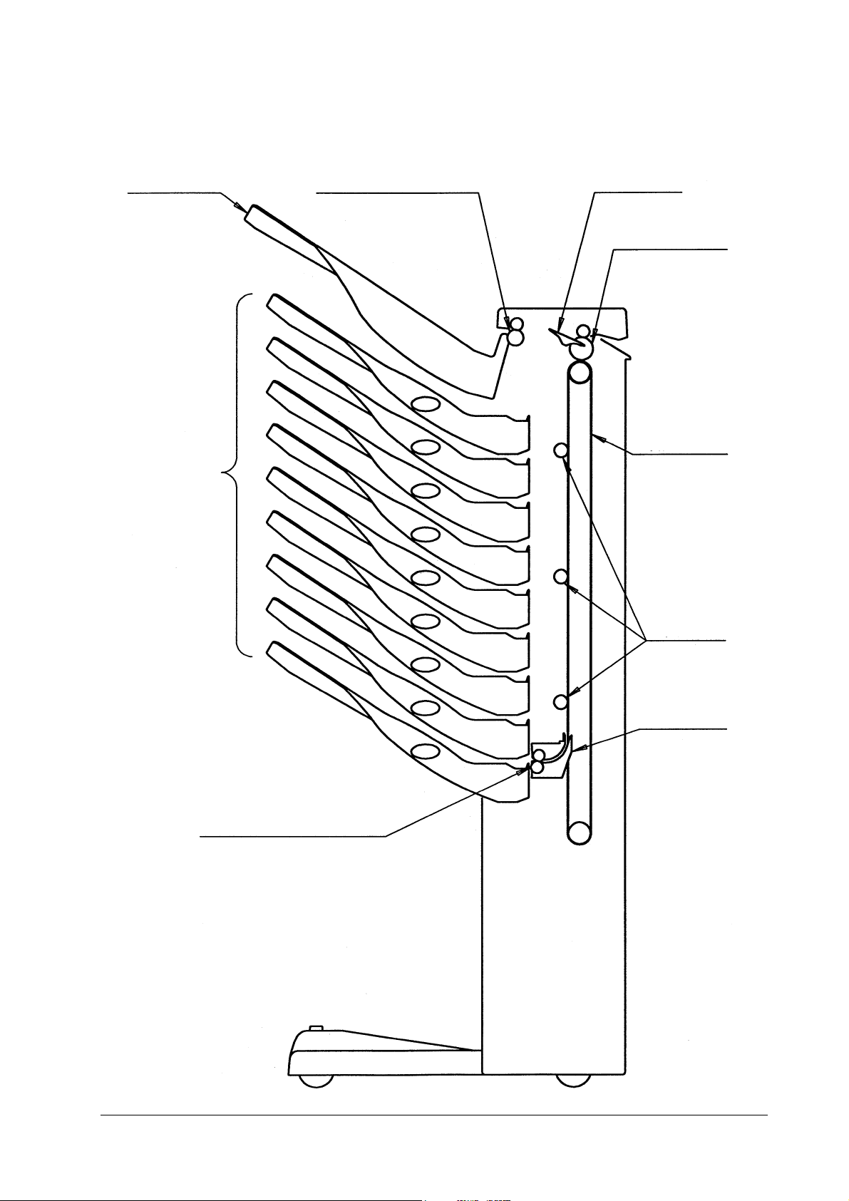
1.2 Mechanical Section
Multi Tray Paper Eject and Reverse Roller Flapper
Vertical Transport Belt
Mail Trays
Entry Roller
Indexer Eject Paper Roller
Vertical Transport
Runners
Indexer
1-3
SO-30
Page 8
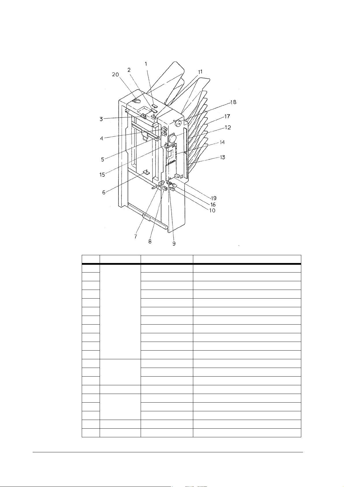
1.3 Electrical Parts
No. Name Symbol Function
1 Sensor LRLED Eject Paper Sensor LED
2 PRSL Paper Reverse Sensor LED
3 PES (S1) Paper Entry Slot Sensor
4 IULS (S2) Indexer Upper Limit Sensor
5 IHPS (S3) Home Position Sensor
6 PT (S4) Eject Paper Sensor Detector
7 SJS (S5) Sorter Joined Sensor
8 ILLS (S6) Indexer Lower Limit Sensor
9 IMCS (S7) Indexer Motor Encoder Cl oc k Se ns or
10 IPS (S8) Indexer Motor Position Detection Sensor
11 PRS (S9) Paper Reverse Sensor Detector
12 Circuit Board PBA-SEN1 Sensor Printed Circuit Board1
13 PBA-SEN2 Sensor Printed Circuit Board2
14 PBA-CONTROL Control PCB
15 Switch DOORSW (SW1) Door Open/Close Switch
16 Motor IM (M1) Indexer Motor
17 PFM (M2) Paper Feeding Motor
18 RMOT (M3) Paper Reverse Motor
19 Power Unit PWS-DENGEN Power
20 Solenoid FSOL (SOL1) Face-Up Solenoid
SO-30
1-4
Page 9
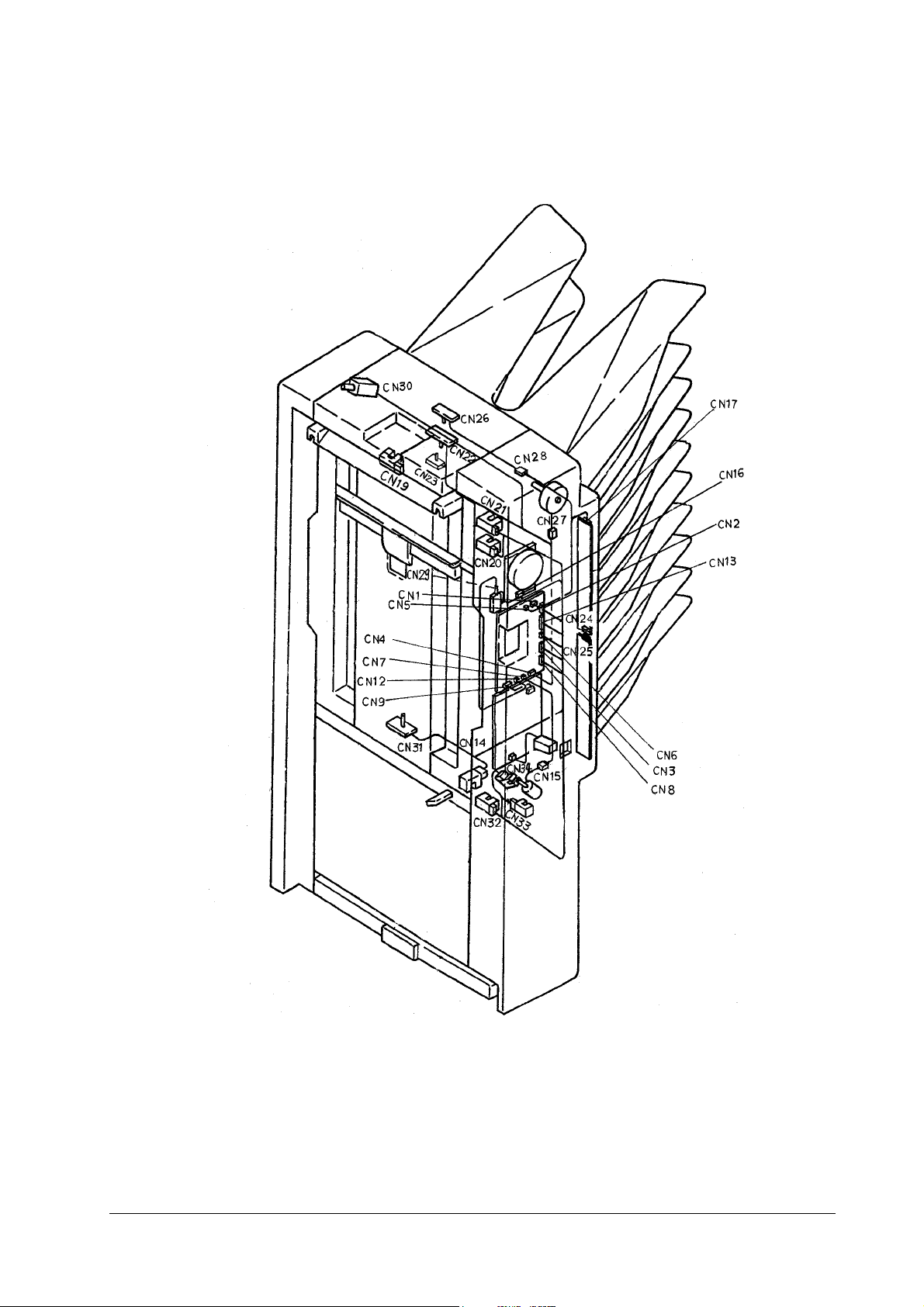
1.4 Connector Layout
1-5
SO-30
Page 10

Chapter 2 MECHANICAL SYSTEM
Contents
General 2-2
Removing the front cover and rear cover 2-3
Removing the top cover 2-3
Removing the cover (black) 2-4
Removing the top tray 2-4
Removing the bracket 2-5
Removing the trays 2-5
Removing the bracket (silver) 2-6
Removing the solenoid 2-7
Removing the motor assembly 2-7
Removing the paper guide 2-8
Removing the bracket (gold) 2-10
Removing the cover 2-11
Removing the index 2-12
Page 11

2.1 General
This chapter explains the mechanical features, operations and procedures for dismantling and
assembling the device. Ensure that the following precautions are observed when proceeding
with these tasks.
Caution Always disconnect the power supply from the socket when dismantling or reas-
sembling the device.
Unless otherwise stated, assembly procedures should be performed in the reverse
sequence to dismantling.
Care must be taken not to use the wrong screws (length, diameter) during assembly.
Never attempt to operate the device with parts removed.
Discharge static electricity from the body by touching a metal part of the device
prior to removing or replacing circuit boards to prevent them from being damaged through static electricity.
SO-30
2-2
Page 12
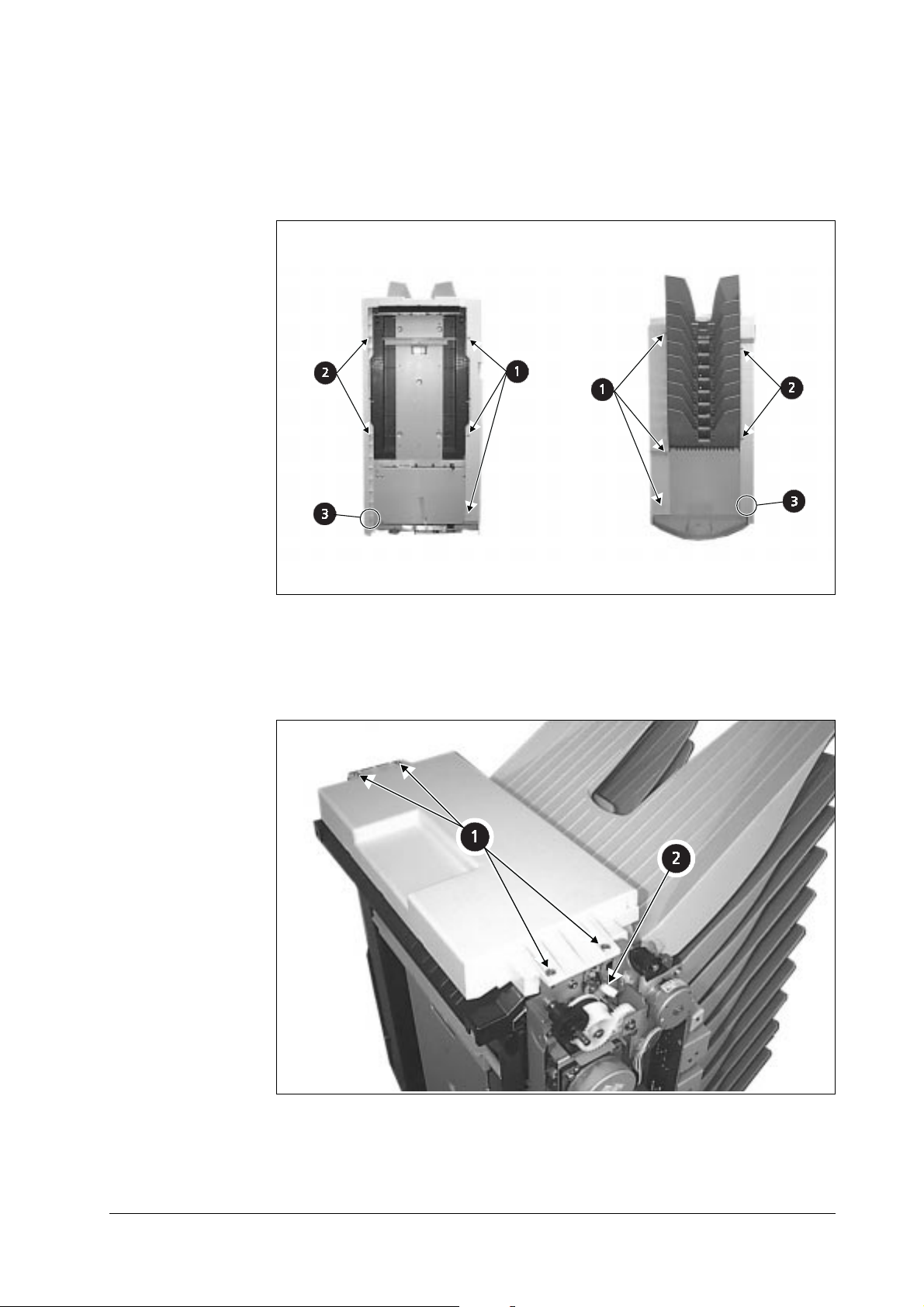
Removing the front cover and rear cover
Remove the six screws (① below).
1
Remove the four screws (② below) and the two tabs (③ below) from the rear cover.
2
2
3
1
1
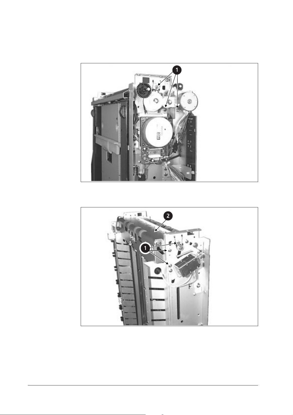
Removing the top cover
Remove the four screws (① below) and the single connector (② below).
2
3
2-3
1
2
SO-30
Page 13
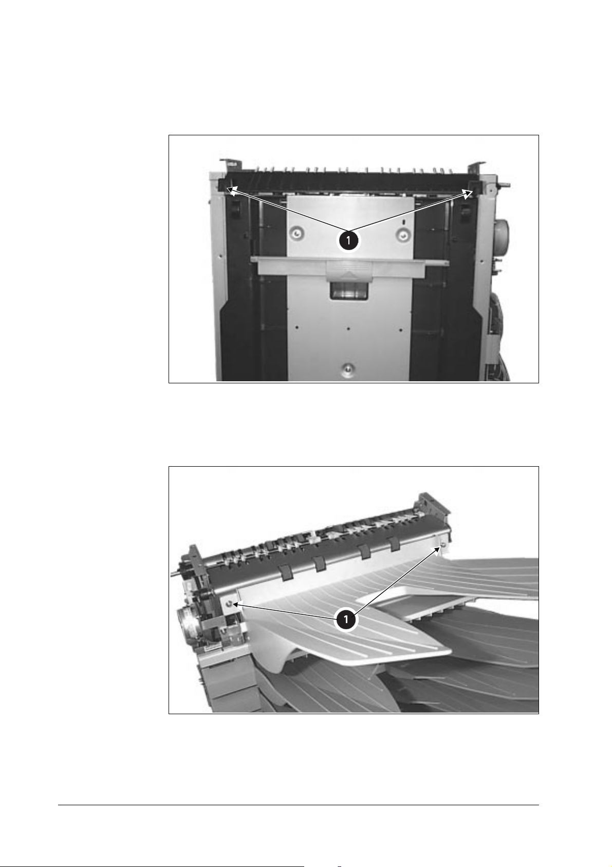
Removing the cover (black)
Remove the two screws (① below).
1
Removing the top tray
Remove the two screws (① below) and pull forward.
1
SO-30
2-4
Page 14
Removing the bracket
Pull the bracket forward (① below).
1
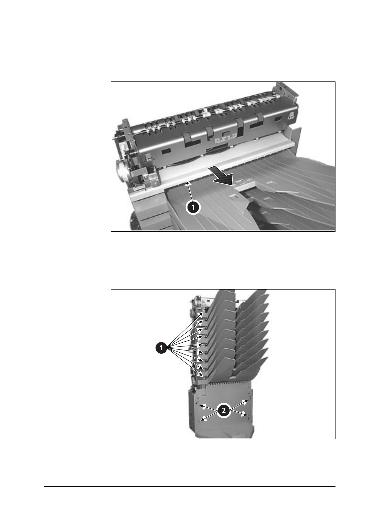
Removing the trays
Remove the screw (① below) from the tray to be removed, then pull the tray forward. (Each tray
is fastened with one screw.) Then remove the four screws (② below) and go to the next step.
1
2
2-5
SO-30
Page 15
Removing the bracket (silver)
Remove the three screws (① below) from the front.
1
1
Remove the three screws (① below) from the rear, the remove the cover (② below).
2
2
1
SO-30
2-6
Page 16
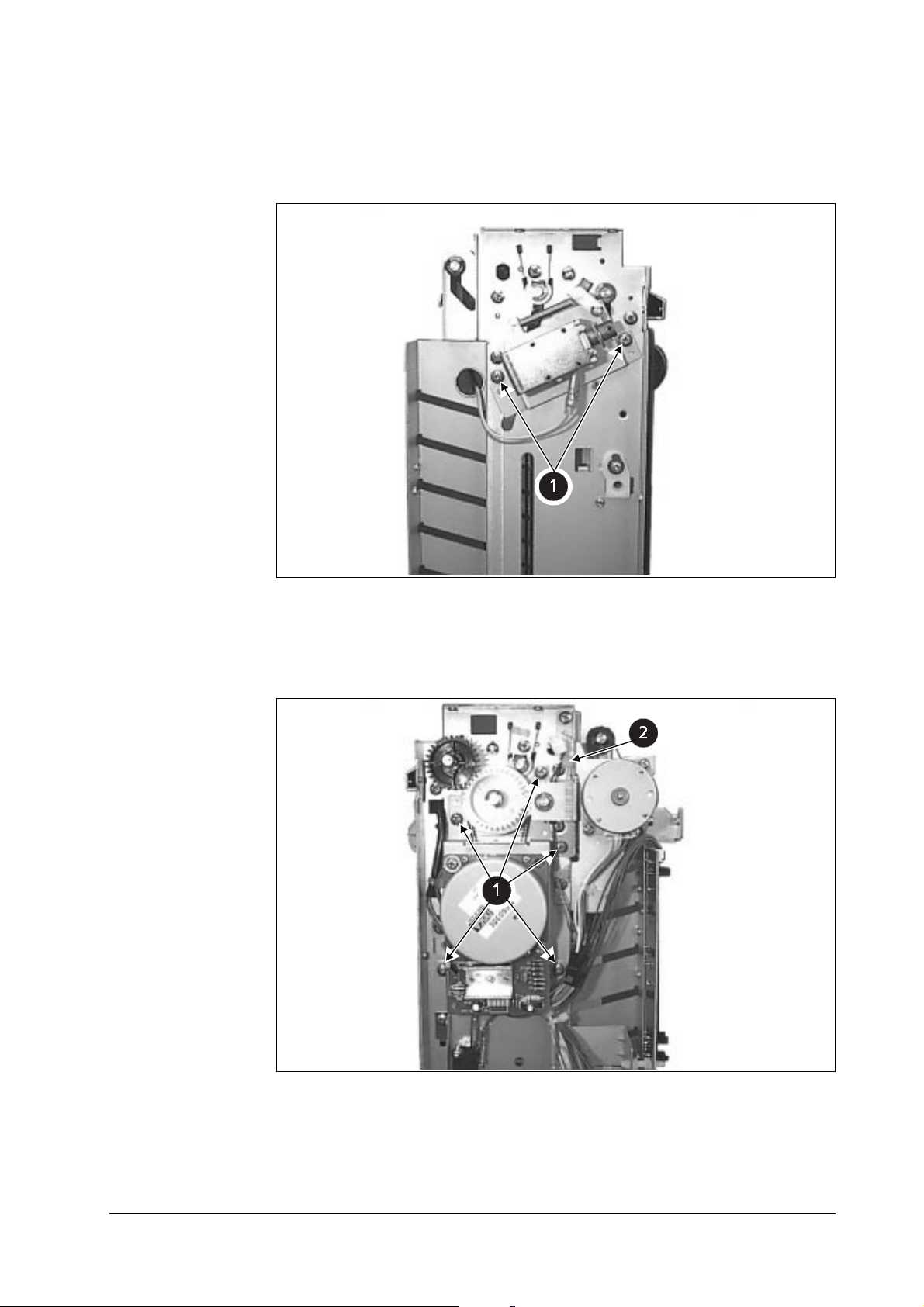
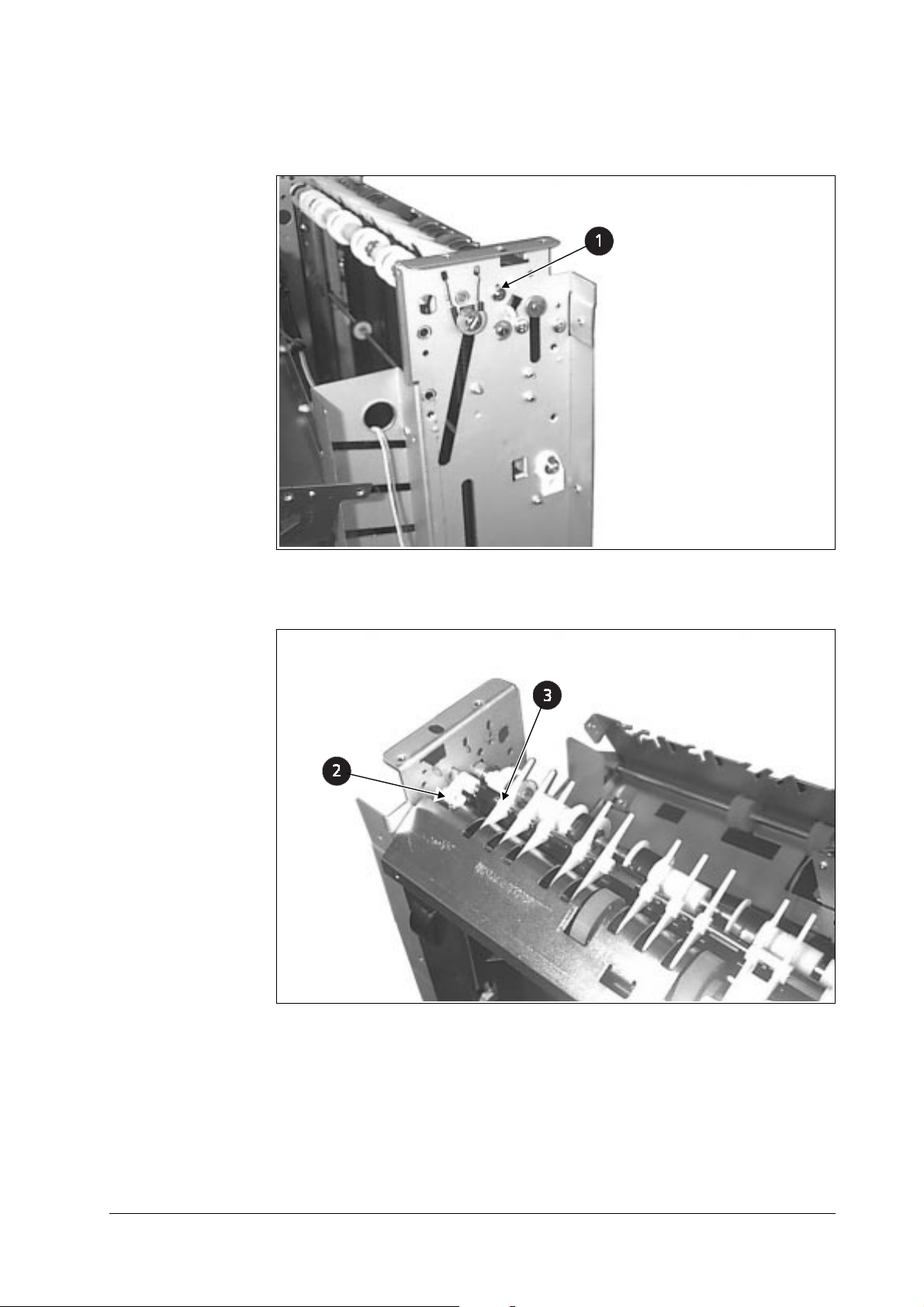
Removing the solenoid
Remove the two screws (① below).
1
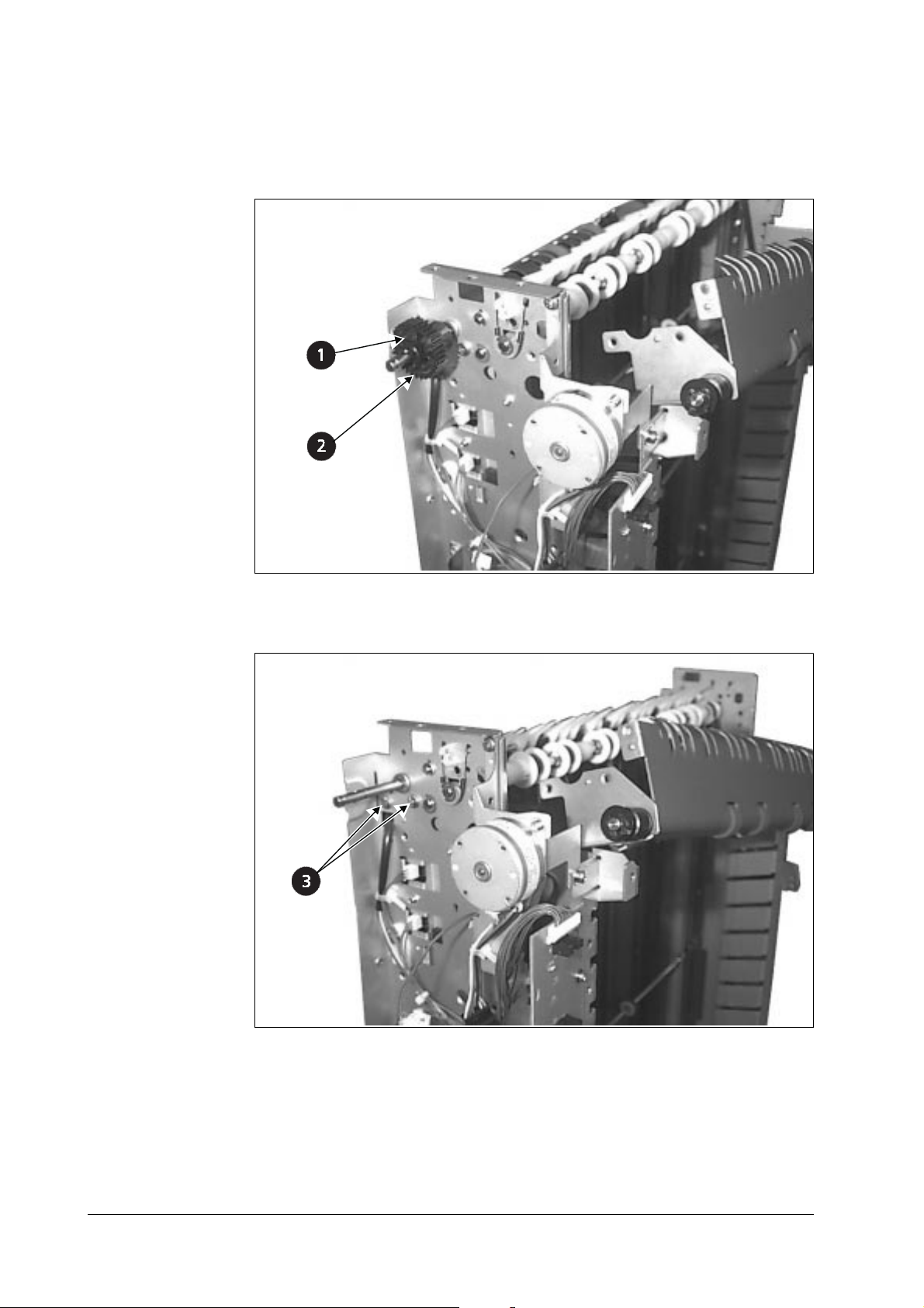
Removing the motor assembly
Remove the five screws (① below), then remove the cord clamper (② below).
1
2
1
2-7
SO-30
Page 17
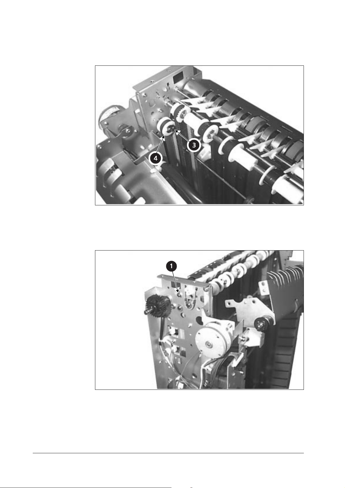
Remove the stop ring (③ below), then remove the gear (④ below).
2
3
4
Removing the paper guide
Remove the front E-ring (① below).
1
1
SO-30
2-8
Page 18
Remove the rear E-ring (① below).
2
1
Remove the spring (② below), then remove the paper guide (③ below).
3
3
2
2-9
SO-30
Page 19
Removing the bracket (gold)
Remove the stop ring (① below), then remove the gear (② below).
1
1
2
Remove the two screws (③ below).
2
3
SO-30
2-10
Page 20

Remove the two rear screws (③ below), then remove the bracket (④ below).
3
4
3
Removing the cover
Remove the two screws (① below).
1
1
2-11
SO-30
Page 21

Loosen the two screws (① below), then remove the ground screw (② below).
2
Slide the two stop rings (③ below) and the two gears (④ below) sideways.
3
Slide the bracket (⑤ below) forward and remove it.
4
4
5
3
4
1
Removing the index
Remove the six screws (① below) and remove the black film.
1
2
SO-30
1
2-12
Page 22
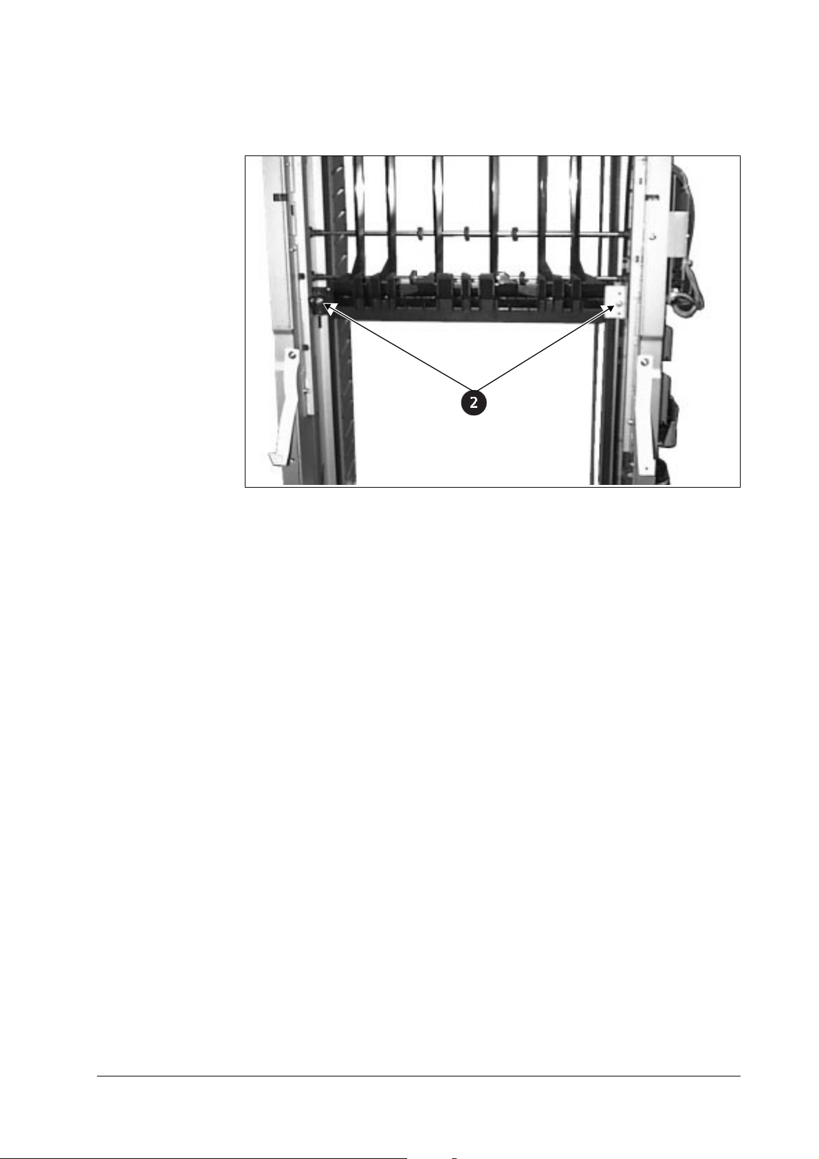
Remove the two screws (② below) and remove the index.
2
2
2-13
SO-30
Page 23

Chapter 3 FUNCTIONAL DESCRIPTION
Contents
Overview 3-2
Multi Bin Paper Eject 3-2
Mail Bin Paper Eject (Reverse Operation) 3-3
Indexer Up/Down Movement 3-4
Circuit Description 3-5
Sensor Connections 3-6
Actuator Connections 3-7
Power 3-8
Overview 3-8
Protection Functions 3-8
Page 24
3.1 Overview
The Indexer Motor (IM) is a DC brush motor, the Paper Feeding Motor (PFM) is a DC brushless motor, and the Paper Reverse Motor (M3) is a stepping motor. Forward and reverse rotation
of these motors is controlled by the microcontroller (CPU) on the Control Board.
The paper feed path contains the Paper Entry Slot Sensor (S1), the Paper Reverse Sensor (S9),
and the Paper Eject Sensor (S4), which detect the presence and transport of the paper. If paper
does not reach or pass each sensor within a certain time, the Control Board detects a jam, stops
operation and notifies the printer that a jam has occurred.
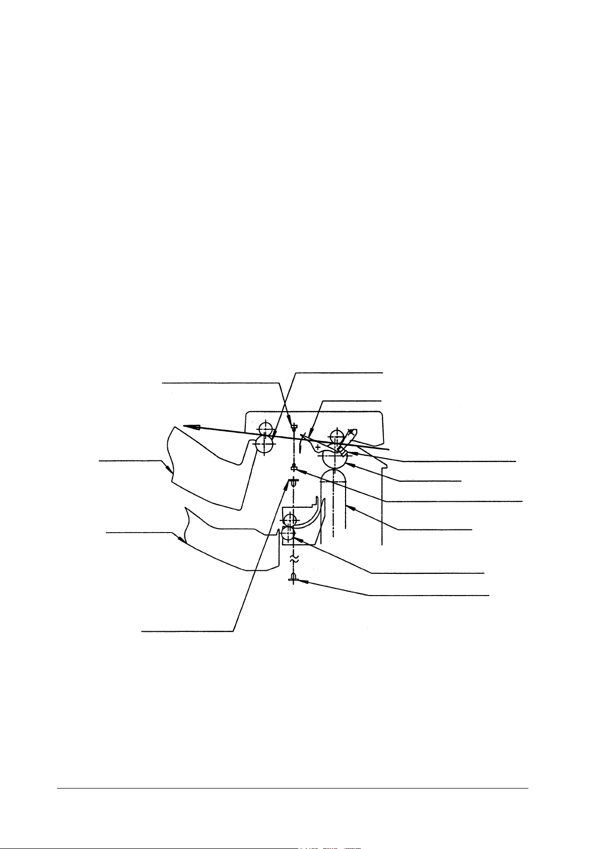
3.2 Multi Bin Paper Eject
When the Control Board receives a Paper Eject signal from the printer, it turns the Paper Feeding Motor (M2) forward, moving the Entry Slot Roller, Vertical Transport Belt and Inde xer
Roller. When the Paper Entry Slot Sensor (S1) detects the edge of the paper, the Paper Reverse
Motor (M3) turns the Eject Paper Reverse Roller forward. The Paper Entry Slot Sensor (S1)
detects the rear edge of the paper, and after the required feeding time, ejects the printed pap er to
the Multi Tray.
Paper Eject and Reverse Roller
Reverse Paper Sensor LED
Flapper
Multi Tray Paper Entry Slot Sensor (S1)
Entry Roller
Paper Reverse Sensor (S9) Detector
Mail Trays
Paper Eject Sensor LED
Vertical Transport Belt
Indexer Eject Paper Roller
Paper Eject Sensor Detector (S4)
SO-30
3-2
Page 25
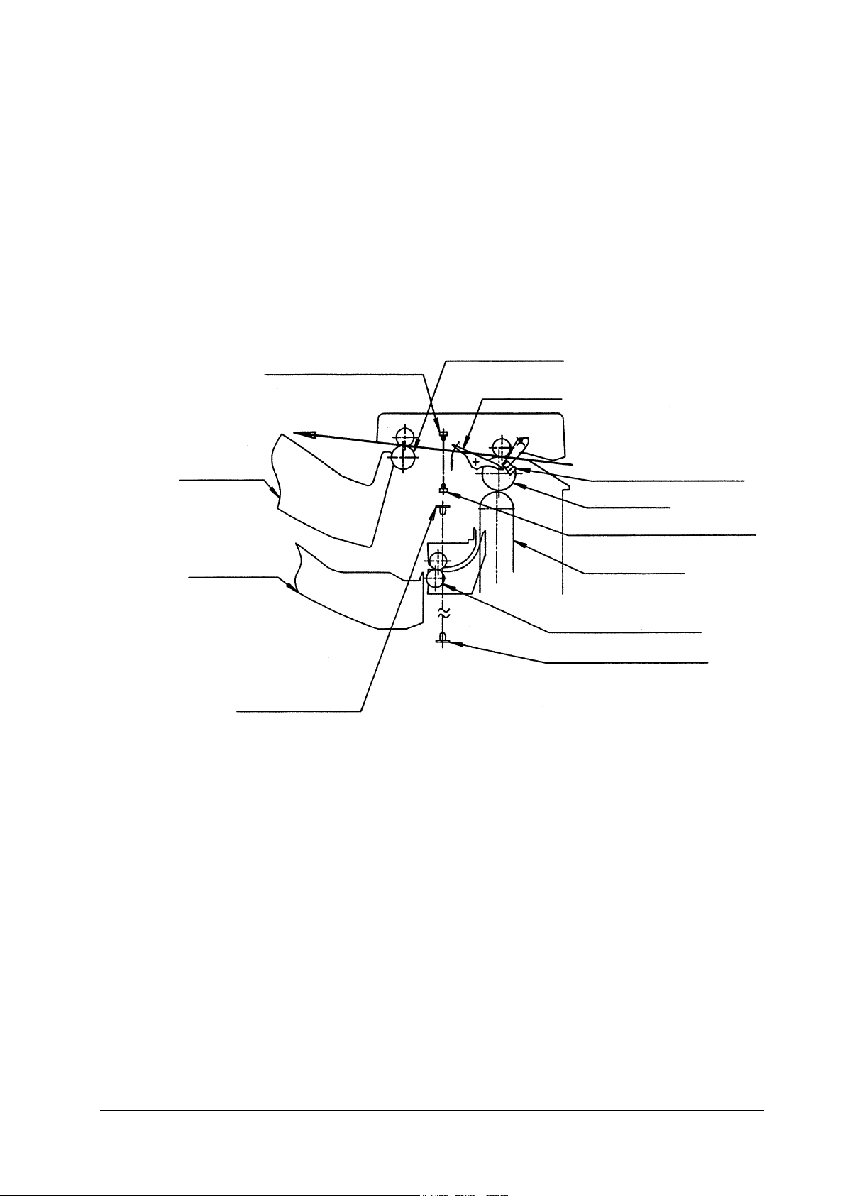
3.3 Mail Bin Paper Eject (Reverse Operation)
When the Control Board receives an Eject signal from the printer, it turns the Paper Feeding
Motor (M2) forward, moving the Entry Roller, Vertical Transport Belt and Ind exer Roller.
When the Paper Entry Slot Sensor (S1) detects the edge of the paper, the Paper Reverse Motor
(M3) turns the Eject Paper Reverse Roller forward . When the Paper Rev erse Sensor ( S1) detects
the rear edge of the paper, the Paper Reverse Motor (M3) stops. The pap er is fe d to the Reverse
position, and the Paper Reverse Motor (M3) turns in reverse so the paper feeds to the Vertical
Transport Belt. The Vertical Transport Belt carries the paper to the Reverse Roller and the
Indexer Eject Paper Roller. The rear edge of the printed paper is detected by the Paper Eject
Sensor (S4), and after the required feeding time, it is ejected to one of the Mail Bins.
Paper Eject and Reverse Roller
Reverse Paper Sensor LED
Flapper
Multi Tray
Mail Trays
Paper Entry Slot Sensor (S1)
Entry Roller
Paper Reverse Sensor (S9) Detector
Vertical Transport Belt
Indexer Eject Paper Roller
Paper Eject Sensor Detector (S4)
Paper Eject Sensor LED
3-3
SO-30
Page 26

3.4 Indexer Up/Down Movement
The Indexer Motor (M1) moves the Indexer up and down. When the Indexer Motor turns in
reverse direction, the Indexer moves downward, and when it turns forward, the Indexer moves
upward. The Indexer Motor Encoder Clock Sensor (S7) regulates the speed of the Indexer
Motor. The Indexer stopping position for each mail tray is detected by the Indexer Motor Position Sensor (S8), and the Indexer Motor (M1) is controlled according to the clock pulses generated by the sensor. The Home Position Sensor (S3) indicates the initial index e r sensor position.
The range of movement of the indexer is monitored by the Indexer Upper Position Sensor (S2)
and the Indexer Lower Limit Sensor (S6).
Indexer Upper Limit Sensor (S2)
Home Position Sensor (S3)
Indexer
Indexer Motor Encoder Clock Sensor (S7)
Indexer Motor (M1)
Indexer Lower Limit Sensor (S6)
Indexer Motor Position Sensor (S8)
Mail Trays
SO-30
3-4
Page 27
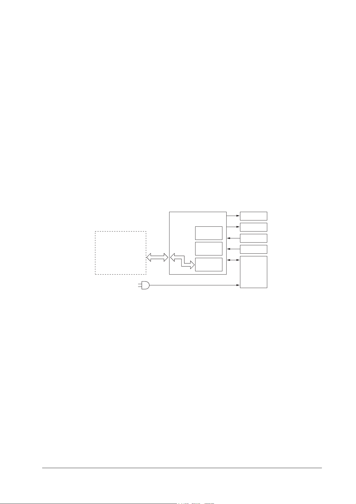
3.5 Circuit Description
i
The operating sequence of the Mailbox Sorter is controlled by the Control Board. A 16-bit
microcontroller (CPU) controls the circuitry, performs sequence control and serial communications.
The Control Board operates the solenoid and the motors in response to various commands sent
from the option (host) controller through the serial commu nications circuit.
The Control Board also advises the option controller of the states of the various sensors and
switches through the serial circuit.
The roles of the ICs on the Control Board are as follows.
•Q1 (CPU)
Sequence Control
•Q2 (EP-ROM)
Internal Sequence Program Firmware
•Q3 (IPC)
Communications Control
The signal flow between the Mailbox Sorter and the printer is shown below.
Printer
Control Board
Q1
CPU
Q2
EP-ROM
Q3
IPC
Motors
Solenoid
Switch
Sensors
Power
Supply Un
3-5
SO-30
Page 28
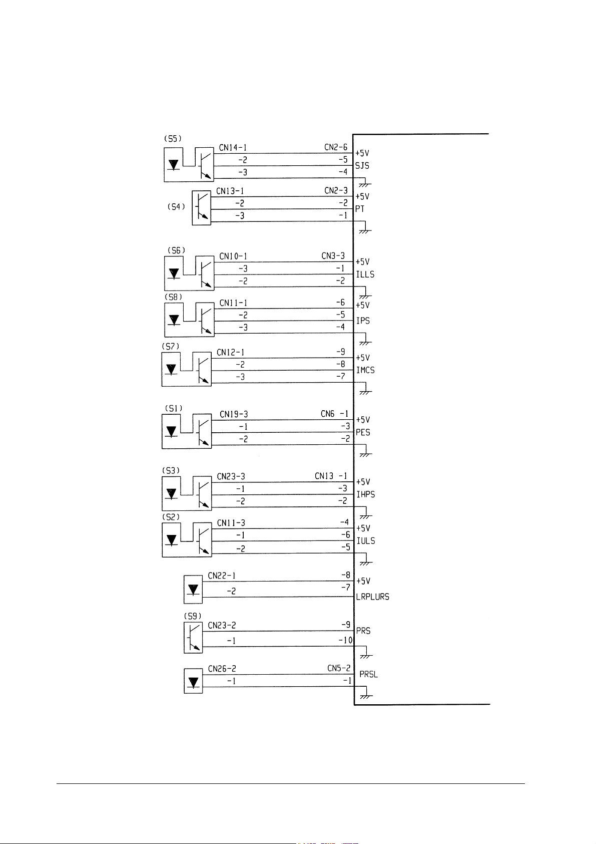
3.6 Sensor Connections
Mailbox Sorter Control Board
Sorter Joined Sensor
Eject Paper Sensor
Detector
Indexer Lower Limit
Sensor
Indexer Motor Position
Sensor
Indexer Motor Encoder
Clock Sensor
Paper Entry Slot Sensor
"L" when joined to printer
"L" when paper detected
"H" when lower limit detected
Pulses according to speed of
indexer motor positioning
Pulses according to speed of
indexer motor encoder
"L" when paper detected
Home Position Sensor
Indexer Upper Limit
Sensor
Eject Paper Sensor LED
Reverse Paper Sensor
Detector
Reverse Paper Sensor LED
"H" when the indexer detects
the home position
"H" when the indexer detects
the upper limit
"L" when the sensor detects paper
SO-30
3-6
Page 29

3.7 Actuator Connections
Indexer Motor
Paper Feeding Motor
Reverse Paper Motor
Mailbox Sorter Control Board
Indexer Motor Control Signals
Feeding Motor Control Signals
Face-Up Solenoid
Door Open/Close Switch
Reverse Paper Motor Control Sign
Face-Up Solenoid Control Signal
3-7
SO-30
Page 30
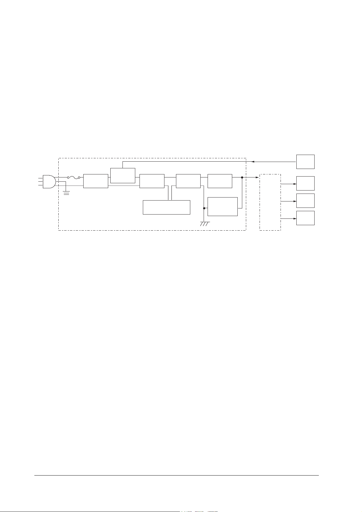
3.8 Power
e
i
Overview
Electrical power to this unit is controlled by a remote switching system .
When the printer power is turned on, the printer outputs remote signal (RMOT), which turns the
unit on. Both +24 and +5 V are supplied to the Control Board when RMOT is H.
The +24V runs the Feeding Motor, Eject Paper Motor and the Solenoid. The +5V supplies the
sensors and ICs on the Control Board.
The following block diagram shows the power supply circuitry.
Power Supply Unit
Noise Filter
Remote
Control
Circuit
Smoothing
Circuit
Control IC Overcurrent
Protection Circuit
Trans-
former
Smoothing
Circuit
Overvoltage
Protection
Circuit
RMOT
+24V
Control
Board
+5V
+24V
+24V
Print
Sensor
Soleno
Motors
Protection Functions
The +24V power circuitry includes an overcurrent protection function to prevent damage by
shutting off the output voltage automatically when a short-circuit-type fault occurs at the load
side causes excessive current drain.
When the overcurrent protection function is triggered and DC voltage is removed from the output of the power circuitry, printer power should be turned off until th e fault on the load side is
repaired.
SO-30
3-8
Page 31

Chapter 4 TROUBLESHOOTING
Contents
Power Does Not Turn On 4-2
Paper Reverse Sensor Fault 4-3
Eject Paper Sensor Fault 4-3
Door Open/Close Switch Fault 4-4
Paper Feeding Motor Fault 4-4
Paper Reverse Motor Fault 4-5
Indexer Motor Fault 4-5
Face-Up Solenoid Fault 4-5
Page 32

Observe the following precautions when performing the troubleshooting procedures in this
chapter.
When measuring voltages specified at various connector terminals, confirm that the connector
is making proper contact.
When handling the circuit board, be careful to avoid damage to the board from static electricity: before starting work, touch the printer’s metal chassis with your hand to discharge static.
4.1 Power Does Not Turn On
Possible Causes:
Specified voltage is not present at the mains outlet.
1
Solution: Advise the user that mains voltage is not present.
The power plugs at the printer, Mail Sorter or outlet are not connected correctly.
2
Solution: Re-insert the power plugs.
The Power-On signal is not being input because of bad connection at the interface connec-
3
tor.
Solution: Reconnect the interface connector
The Power-On signal is not available.
4
Solution: Turn on the printer, and measure the voltage on the Control Board between
connectors CN9-1 (RMOT) and CN9-3 (GND). If the voltage is not about 3V,
check the printer.
Blown fuse
5
Solution: Remove the Power Supply Unit and replace the fuse.
Power Supply Unit fault
6
Solution: Turn off the printer and remove connector CN9 from the Control Board.
Connect the power cord to the Power Supply Unit, tu rn th e printer on, and
measure the DC output at connector CN9 (be careful to avoid short circuits).
If the specified voltage is not present, replace the Power Supply Unit.
Wiring, DC Loads and Control Board
7
Solution: Turn off the printer, and ch eck th e wiring an d DC load s served by the Control
Board. If the wiring and DC loads check okay, replace the Control Board.
SO-30
4-2
Page 33

4.2 Paper Reverse Sensor Fault
Possible Causes:
Bad Paper Reverse Sensor signal line connection
1
Solution: Reconnect connectors CN13 and CN5 on the Control Board. Also reconnect
connector CN23 at the detector side of the Paper Reverse Sensor, CN26 at the
LED side of the Paper Reverse Sensor, and relay connector CN28.
Bad Paper Reverse Sensor
2
Solution: Measure the voltages between connectors CN13-10 (SGND) and CN13-9, and
CN5-2 on the Control Board.
(1) About 120 mV should be present at CN13-10 and CN13-9 (relative to
GND).
(2) About 1.2 V should be present between CN5-1 and CN5-2.
If the above voltages are not present, replace the LED side of the Paper
Reverse Sensor (PRSL) and the detector side of the Paper Reverse Sensor
(PRS).
Bad Control Board
3
Solution: Replace the Control Board.
4.3 Eject Paper Sensor Fault
Possible Causes:
Bad Eject Paper Sensor signal line connection
1
Solution: Reconnect connectors CN13 and CN2 on the Control Board. Also reconnect
connector CN31 for th e detect or s ide o f t h e Ej ect P aper S ens or, and CN22 for
the LED side of the Eject Paper Sensor.
Bad Eject Pap er Sensor
2
Solution: Measure the voltages at co nnectors CN13-7 (*LRPLUS) on the Mailbox
Sorter and the Driver Board, and CN13-8 and CN2-2.
(1) About 5 V should be present at CN13-7 and CN13-8.
(2) About 4.5 V should be present between CN2-1 and CN3-2.
If the above voltages are not present, replace the LED side of the Eject
Paper Sensor (LRLED) and the detector side of the Eject Paper Sensor
(PT).
Bad Control Board
3
Solution: Replace the Control Board.
SO-30
4-3
Page 34

4.4 Door Open/Close Switch Fault
Possible Causes:
Bad Door Open/Close Switch signal line conn ection
1
Solution: Reconnect CN12 on the Control Board. Also reconnect connector CN29 on
the Door Open/Close Switch.
Bad Door Open/Close Switch
2
Solution: Remove connector CN12 on the Control Board, and measure the resistance
between CN12-1 and CN12-2 on the switch side. When the Vertical Transpo rt
Unit is closed, the resistance should be 0 (, and when opened, the resistance
should be infinite. Otherwise, replace the Door Open/Close Switch.
4.5 Paper Feeding Motor Fault
Possible Causes:
Bad Paper Feeding Motor signal line connection
1
Solution: Reconnect connector CN8 on the Control Board. Also reconnect connector
CN16 on the Paper Feeding Motor.
Bad Paper Feeding Motor
2
Solution: Activate the test mode by turning on DIP switches 3 and 4 on the Control
Board, to confirm whether the Paper Feeding Motor operates or not. If the
motor does not operate, replace it.
Bad Control Board
3
Solution: Replace the Control Board.
SO-30
4-4
Page 35

4.6 Paper Reverse Motor Fault
Possible Causes:
Bad Paper Reverse Motor signal line connection
1
Solution: Reconnect connector CN4 on the Control Board. Also reconnect connector
CN27 on the Paper Reverse Motor.
Bad Paper Reverse Motor
2
Solution: Remove connector CN4 on the Control Board, and measure the resistance
between at the motor side of the connector as follows:
(1) Between CN4-1 and CN4-5, and between CN4-1 and CN4-6.
(2) Between CN4-2 and CN4-3, and between CN4-2 and CN4-4.
If any measurement is not about 15 (, replace the Paper Reverse Motor.
Bad Control Board
3
Solution: Replace the Control Board.
4.7 Indexer Motor Fault
Possible Causes:
Bad Indexer Motor signal line connection
1
Solution: Reconnect connector CN7 on the Control Board. Also reconnect connector
CN15 on the Paper Reverse Motor.
Bad Indexer Motor
2
Solution: Remove connector CN7 on the Control Board, and measure the resistance
between at the motor side of the connector between CN7-1 and CN7-2. If the
resistance is not about 8.6 (, replace the Indexer Motor.
Bad Control Board
3
Solution: Replace the Control Board.
SO-30
4.8 Face-Up Solenoid Fault
Possible Causes:
Bad Face-Up Solenoid signal line connection
1
Solution: Reconnect connector CN4 on the Control Board. Also reconnect connector
CN30 on the Face-Up Solenoid.
Bad Face-Up Solenoid
2
Solution: Remove connector CN4 on the Control Board, and measure the resistance
between at the solenoid side of the connector between CN4-7 and CN4-8. If
the resistance is not about 115 (, replace the solenoid.
Bad Control Board
3
Solution: Replace the Control Board.
4-5
Page 36

Appendice PARTS CATALOGUE
Contents
External Covers A-2
Paper Conveying Assembly A-4
Frame Assembly A-7
Tray Mail Assembly 1-8 A-9
Tray Mail Assembly 9 A-11
Drive Assembly A-13
Multi Tray, Door Assembly A-17
Base Assembly A-19
Wiring Diagram A-21
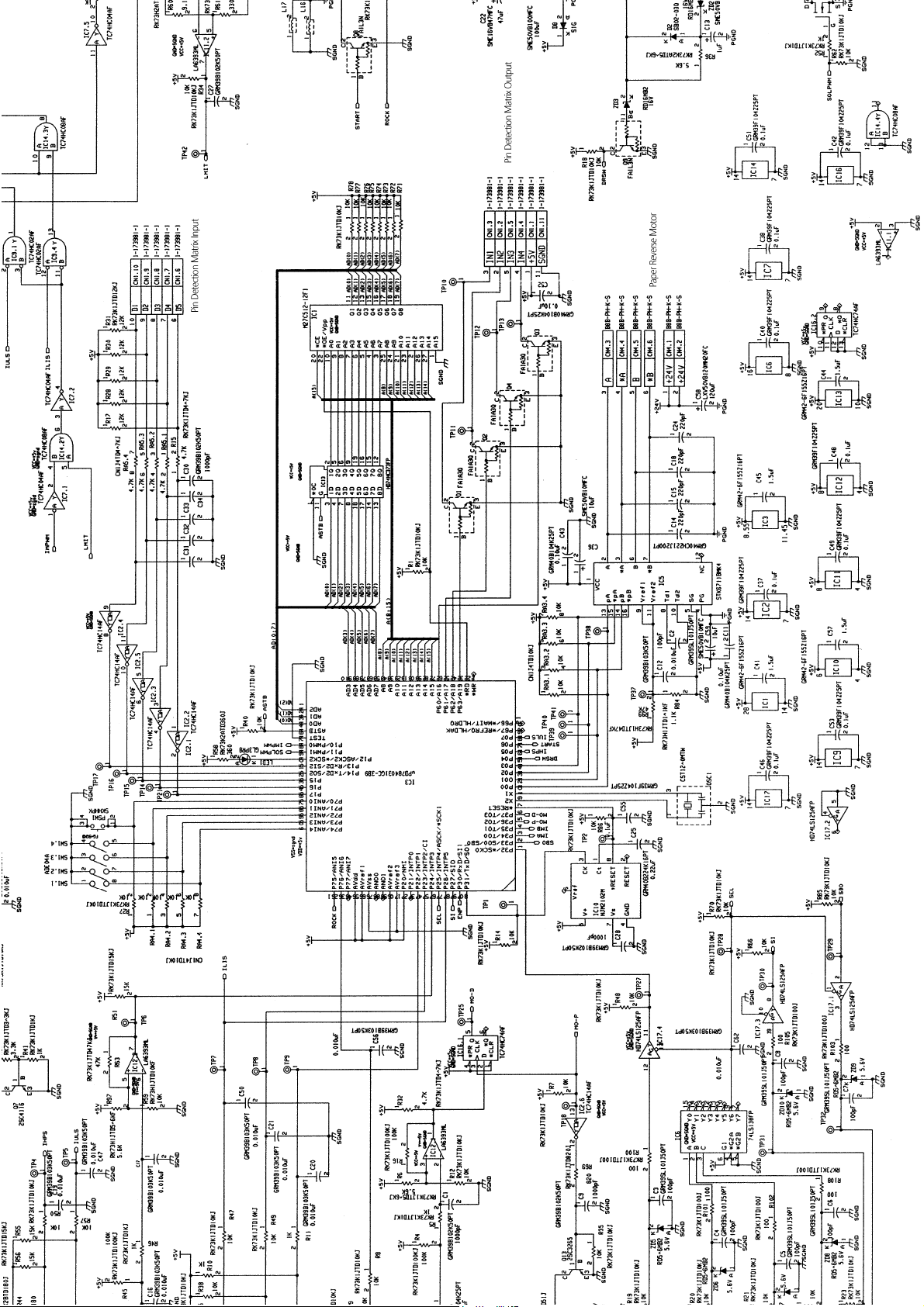
Schematic Diagram A-22
Page 37
A-1 External Covers
A
SO-30
A-2
Page 38

Ref. No. Part code Description Remarks
01-A 5SNSASO30E32 COVER TOP ASSEMBLY
01-001 5SNSP0012739 COVER FRONT
01-002 5SNSP00127 40 COVE R REAR
01-003 5SNSP0012698 COVER TOP
01-004 5SNSP0012703 BRUSH EXIT
01-005 5SNSP0012704 PLATE EARTH EXIT
01-006 5SNSP0012702 LEVER SENSOR TOP
01-007 5SNSASO30E19 PWB SENSOR TOP
01-008 5SNSP0012699 PLATE SPRING ROLLER
01-009 5SNSP0012700 ROLLER TOP
01-010 5SNSP0012701 SHAFT ROLLER TOP
01-011 5SNSASO30E20 CONN. ASM-CK2
01-012 5SNSP0012750 CLAMP WIRE
01-a 5MBSPB4008NN BIND HD SCREW
01-b 5MBTPB4010WZ BIND T-T SCREW
01-c 5MBTPB3008WZ BIND T-T SCREW
SO-30
A-3
Page 39

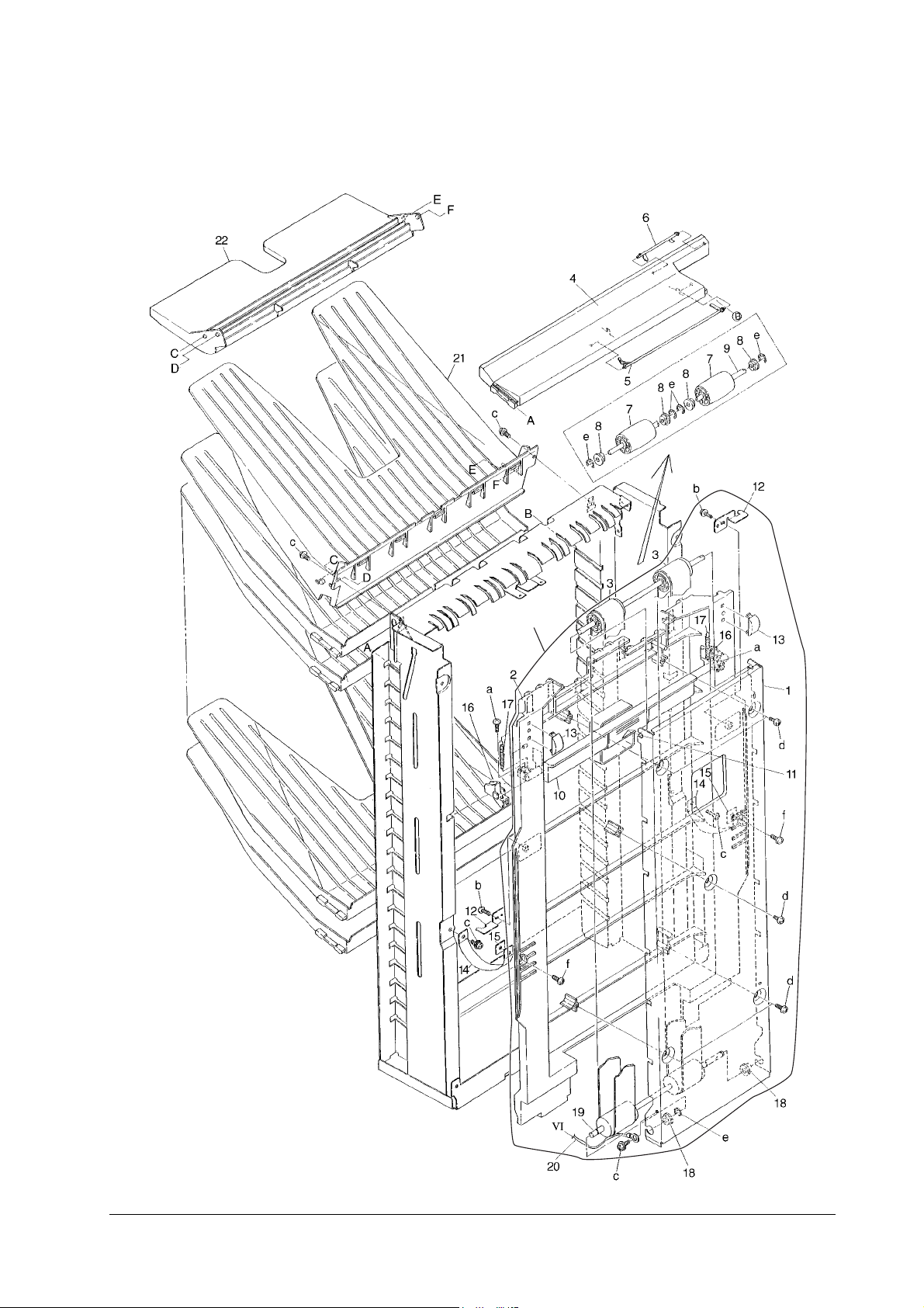
A-2 Paper Conveying Assembly
SO-30
B
F
A-4
Page 40

Ref. No. Part code Description Remarks
02-B 5SNSASO30E33 INDEXER ASSEMBLY
02-F 5SNSASO30E37 REEL FILM ASSEMBLY
02-001 5SNSP00127 05 SHAFT GUIDE 2
02-002 5SNSP00127 10 GUIDE UPPER
02-003 5SNSP00127 08 SHAFT GUIDE 1
02-004 5SNSP00127 09 GUIDE C ENT ER
02-005 5SNSP00127 06 ROLLER GUIDE
02-006 5SNSP0012707 GUIDE LOWER
02-007 5SNSP00126 56 ROLLER INDEXER
02-008 5SNSP0012633 FLAPPER
02-009 5SNSP0012634 GUIDE FLAPPER
02-010 5SNSP0012636 SPRING FLAPPER
02-011 5SNSP00126 37 GUIDE PAPER EXIT
02-012 5SNSASO30E07 PWB LR43
02-013 5SNSP0012749 SENSOR TLP1241
02-014 5SNSASO30E04 CONN. CORD ASSEMBLY PES
02-015 5SNSP00126 09 GUIDE PAPER ENTRANCE
02-016 5SNSP0012608 BUSHING 6
02-017 5SNSP0012657 FRAME INDEXER UPPER
02-018 5SNSP0012667 BRUSH INDEXER LOWER
02-019 5SNSP0012638 ROLLER EXIT
02-020 5SNSP0012658 PLATE INDEXER
02-021 5SNSP0012662 GUIDE INDEXER I
02-022 5SNSP00126 60 ROLLER INDEXER W
02-023 5SNSP00126 59 ROLLER INDEXER A
02-024 5SNSP00126 61 SPRING INDEXER A
02-025 5SNSP0012629 FILM PAPER GU IDE
02-026 5SNSP0012631 GUIDE FILM 2
02-027 5SNSP0012630 GUIDE FILM 1
02-028 5SNSP0012649 HOLDER INDEXER
02-029 5SNSP00126 52 ROLLER INDEXER BELT
02-030 5SNSASO30E10 BKT INDEXER
02-031 5SNSP0012664 PULLEY GEAR Z31
02-032 5SNSP0012665 FLANGE PULLEY
02-033 5SNSP0012666 GEZR Z20
02-034 5SNSP00126 63 PLATE EARTH INDEXER 1
02-035 5SNSP0012653 FRAME INDEXER LOWER
02-036 5SNSP0012654 RIB FRONT INDEXER
02-037 5SNSP0012655 RIB REAR INDEXER
02-038 5SNSP0012755 BUSHING 4
02-039 5SNSP0012744 WIRE CLAMP
02-040 5SNSP0012750 WIRE CLAMP
02-041 5SNSP00126 10 CUSHION SENSOR
02-042 5SNSP0012585 SHEET
SO-30
A-5
Page 41

Ref. No. Part code Description Remarks
02-043 5SNSP00126 70 PLATE EARTH INDEXER 2
02-044 5SNSP0012800 CUSHION GUIDE ROLLER
02-045 5SNSP0012669 BRUSH INDEXER UPPER
02-046 5SNSP00126 50 PLATE EARTH HOLDER 1
02-047 5SNSP00126 51 PLATE EARTH HOLDER 2
02-048 5SNSP00126 11 GUIDE PAPER ENTRANCE
02-049 5SNSP0012635 BUSHING 4
02-050 5SNSP0012639 BKT SENSOR
02-051 5SNSASO30E05 PWB SENSOR
02-052 5SNSP0012640 HOLDER SENSOR
02-053 5SNSP0012675 PULLEY S2M-20
02-054 5SNSP0012674 FLANGE PULLEY
02-055 5SNSP0012648 CLIP 5
02-056 5SNSP00125 92 COVE R SENSOR
02-a 5MBTPB3008WZ BIND T-T SCREW
02-b 5MBSPB4006TZ BIND T-T SCREW
02-c 5MBSPC3006NZ CEMS SCREW
02-d 5MBSPB3003NZ BIND HD SCREW
02-e 5MBSPC3006NZ CEMS SCREW
02-f 5MBCE3060XSP E STOP RING
02-g 5MBP2010WXSP SPRING PIN
02-h 5MBCE5060XSP E STOP RING
02-I 5MBP1208WXSP SPRING PIN
02-j 5MBP1206WXSP SPRING PIN
02-k 5SNSP0012588 M4X7 ROUNDED END
02-l 5MBSPB3006NZ BIND HD SCREW
SO-30
A-6
Page 42

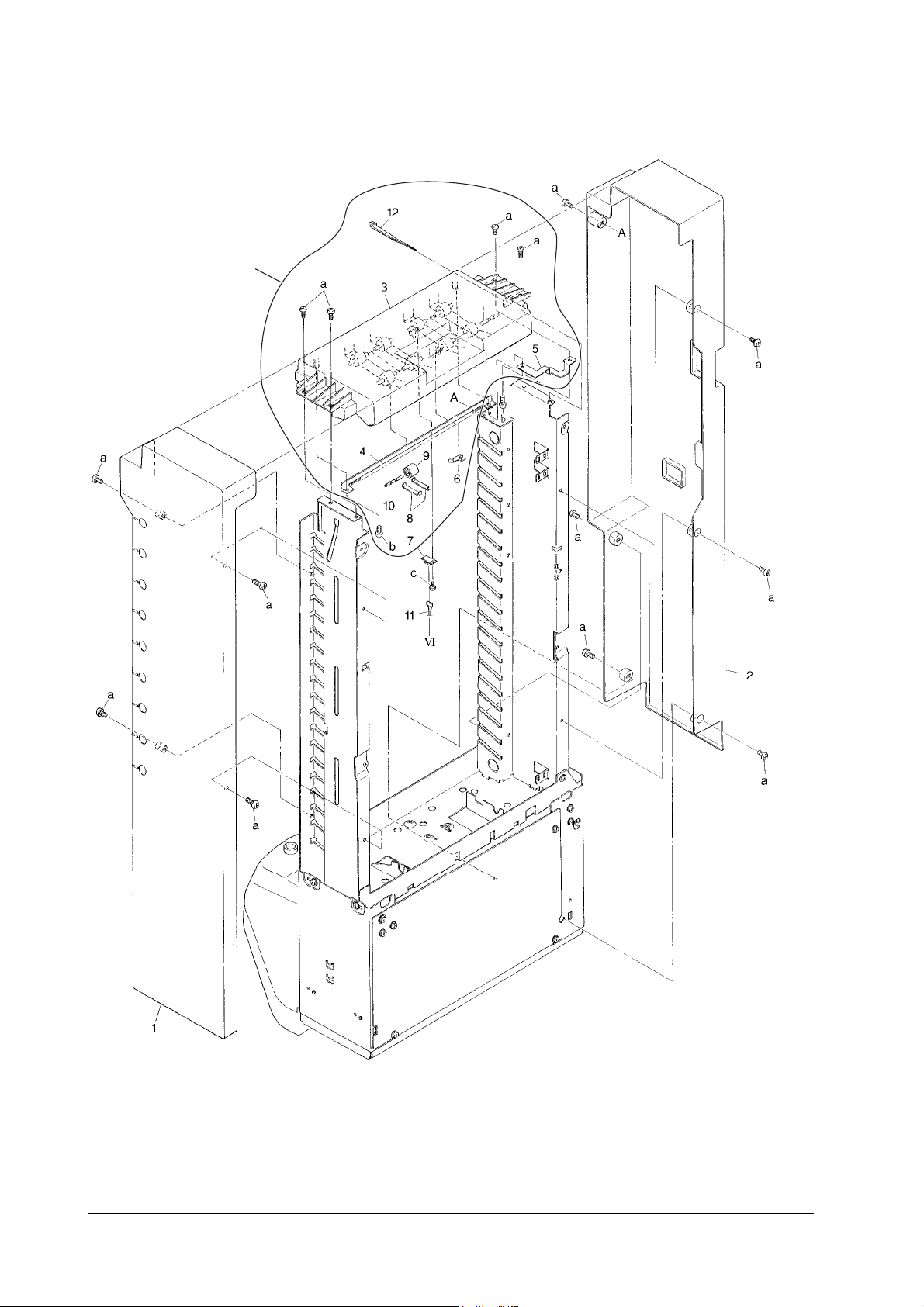
A-3 Frame Assembly
A-7
SO-30
Page 43

Ref. No. Part code Description Remarks
03-01 5SNSP0012599 RAIL INDEXER
03-02 5SNSP001 2711 GUIDE A RAIL
03-03 5SNSP0012605 GUIDE B RAIL
03-04 5SNSP0012596 PIN ROCK
03-05 5SNSP0012597 ACTUATOR K
03-06 5SNSP0012584 BKT SENSOR
03-07 5SNSP0012585 SHEET SENSOR
03-08 5SNSP0012743 SENSOR GP1S74P
03-09 5SNSP001 2592 COVER SENSOR
03-10 5SNSP0012593 FILM SENSOR
03-11 5SNSP0012589 PLATE B STOPPER F
03-12 5SNSASO30E01 PWB PT43
03-13 5SNSP0012586 LEVER SENSOR
03-14 5SNSP0012591 PLATE B STOPPER R
03-15 5SNSP0012600 GUIDE C RAIL
03-16 5SNSP0012594 FRAME FRONT
03-17 5SNSP0012602 FRAME REAR
03-18 5SNSASO 30E02 CONN. CORD ASSMBLY PT
03-19 5SNSP0012744 CLAMP WIRE
03-20 5SNSP0012595 MAT CUSHION
03-21 5SNSP0012587 SPRING LEVER
03-22 5SNSP0012808 COVER CASTER
3-a 5MBSPX4006NZ BRAS. TAP SCREW
3-b 5MBSPX4006NZ BRAS. TAP SCREW
3-c 5SNSP0012590 M4X9 ROUNDED END
3-d 5SNSP0012588 M4X7 ROUNDED END
3-e 5MBSP84010NZ CEMS SCREW W/FW
3-f 5MBSPC3008NZ CEMS SCREW W/FW
3-g 5SNSP0012598 M4X5 ROUND END
SO-30
A-8
Page 44

A-4 Tray Mail Assembly 1-8
A-9
SO-30
Page 45

Ref. No. Part code Description Remarks
04-01 5SNSP0012731 TRAY MAIL
04-02 5SNSP0012732 LEVER EMPTY
04-03 5SNSP0012734 LEVER FULL 1
04-04 5SNSP0012735 LEVER FULL 2
04-05 5SNSP0012801 SPRING LEVER EMPTY
04-06 5SNSP0012802 ADDITIONAL MAIL TRAY
4-a 5MBSPC4008NZ CEMS SCREW
SO-30
A-10
Page 46

A-5 Tray Mail Assembly 9
A-11
SO-30
Page 47

Ref. No. Part code Description Remarks
05-01 5SNSP0012731 TRAY MAIL
05-02 5SNSP0012732 LEVER EMPTY
05-03 5SNSP0012801 SPRING LEVER EMPTY
05-04 5SNSP0012802 ADDITIONAL MAIL TRAY
5-a 5MBSPC4008NZ CEMS SCREW
SO-30
A-12
Page 48

A-6 Drive Assembly
G
A-13
SO-30
Page 49

Ref. No. Part code Description Remarks
06-01 5SNSASO30E25 PWB SENSOR A
06-02 5SNSP0012607 ROLLER ENTRANCE
06-03 5SNSP0012632 SHAFT HANGER FILM
06-04 5SNSP0012621 SHAFT REEL FILM
06-05 5SNSP0012624 ARBOR REEL FILM
06-06 5SNSP0012622 PULLEY REEL FILM
06-07 5SNSP0012746 SPACER KGLS-18S
06-08 5SNSP0012623 SPRING REEL FILM
06-09 5SNSP0012626 SPRING REEL FILM R
06-10 5SNSP0012617 BELT S3M 442 60
06-11 5SNSP0012615 BELT S3M 430 60
06-12 5SNSP0012613 PULLEY S3M 18 A
06-13 5SNSP0012619 PULLEY S3M 18 B
06-14 5SNSP0012627 REEL ADJUST ARBOR
06-15 5SNSP0012628 SPRING REEL ADJUST
06-16 5SNS P0012752 BUSHING MF
06-17 5SNS P0012608 BUSHING 6
06-18 5SNSP0012641 SPRING REEL SHAFT
06-19 5SNSP0012612 SHAFT DRIVE LOWER
06-20 5SNSP0012614 PULLEY S3M 23
06-21 5SNSP0012648 CLIP 5
06-22 5SNSP0012756 WIRE CLAMP
06-23 5SNSP0012616 BELT S3M 57 60
06-24 5SNSP0012743 SENSOR GP1S74P
06-25 5SNSP0012713 BKT CONN. INTER
06-26 5SNSASO30E23 PWB CONT SUB
06-27 5SNSASO 30E24 EPROM Assembly
06-28 5SNSP001 2712 SWITCHING REG.
06-29 5SNSP001 2676 MOTOR INDEXER
06-30 5SNSP0012680 PLATE ENCODER 40
06-31 5SNSP0012679 COLLAR MOTO R
06-32 5SNSP0012678 GEAR WORM
06-33 5SNSP0012677 BKT MOTOR INDEXER
06-34 5SNSP001 2681 BKT SENSOR INDEXER
06-35 5SNSP0012748 SENSOR TLP1225
06-36 5SNSP0012671 PLATE ENCODER 4
06-37 5SNSP0012620 GEAR Z30
06-38 5SNSP0012747 SPACER KGLS-16S
06-39 5SNSP0012618 SHAFT DRIVE INDEXER
06-40 5SNSP0012604 PLATE CONT. PWB
06-41 5SNSP0012745 SW INDEXER POSITION
06-42 5SNSP0012603 BKT PWB SENSOR
06-43 5SNSP0012675 GEAR LIMIT
06-44 5SNSP0012750 WIRE CLAMP SKB-1M
SO-30
A-14
Page 50

Ref. No. Part code Description Remarks
06-45 5SNSASO30E09 BKT MOTOR CONVEYING
06-46 5SNSP0012646 SHAFT DR IVE UPPER
06-47 5SNSP0012647 GEAR Z23
06-48 5SNSP0012754 BEARI NG MF106ZZ
06-49 5SNSP0012753 BE LT S2M 60
06-50 5SNSP0012643 PULLEY IDLER GEAR
06-51 5SNSP0012644 MOTOR CONVEYING
06-52 5SNSP0012645 PU LLEY S2M 16
06-53 5SNSASO30E26 CONN. CORD BIN 2
06-54 5SNSASO30E28 PWB SENSOR B
06-55 5SNSP0012672 BKT MOTOR REVERSE
06-56 5SNSP0012744 WIRE CLAMP
06-57 5SNSP0012803 BE LT S2M 56-40
06-58 5SNSP0012804 MOTOR REVERSE
06-59 5SNSP0012805 BKT REAR COVER
06-60 5SNSASO30E16 BKT SOLENOID
06-61 5SNSP0012682 LEVER FLAPPER
06-62 5SNSP0012683 SOLENOID NS38
06-63 5SNSP0012684 SPRING SOLENOID
06-64 5SNSP0012606 BKT SE NSOR COVER
06-65 5SNSASO30E13 CONN. CORD SENSOR 2
06-66 5SNSASO30E22 CONN. CORD REG.
06-67 5SNSASO30E03 CONN. CORD SW
06-68 5SNSASO30E14 CONN. CORD MOTOR
06-69 5SNSASO30E06 CONN. CORD INDEXER
06-70 5SNSASO30E27 CONN. CORD BIN
06-71 5SNSASO30E15 CONN. CORD MOTOR
06-72 5SNSASO30E12 CONN. CORD TOP
06-73 5SNSP0012585 SHEET SENSOR
06-74 5SNSASO30E08 CONN. CORD REVERSE
06-75 5SNSP0012757 SPACER KGLS-6S
6-a 5MBSPC3006NZ CEMS SCREW
6-b 5MBSPC4012NZ CEMS SCREW
6-c 5MBSPC4008NZ CEMS SCREW
6-d 5MBCG5080XSP G STOP RING
6-e 5SNSP0012588 M4X7 ROUNDED END
6-f 5MBWK30705SZ FLAT S WASHER
6-g 5MBCE3060XSP E STOP RING
6-h 5MBCE5060XSP E STOP RING
6-I 5MBSPC4010NZ CEMS SCREW
6-j 5MBP2010WXSP SPRING PIN
6-k 5MBP2012WXSP SPRING PIN
6-l 5MBVH94008NP HEXA SET SCREW
6-m 5MBSPX4006NZ BRAS. TAP SCREW
A-15
SO-30
Page 51

Ref. No. Part code Description Remarks
6-n 5MBSPC300 6NZ CEMS SCRE W
6-o 5SNSP0012751 WASHER T
6-p 5MBSPB4006NN BIND HD SCREW
6-q 5MBSPC301 6NZ CEMS SCRE W
6-r 5SNSP0012625 FC PARALLEL PIN
SO-30
A-16
Page 52
A-7 Multi Tray, Door Assembly
H
A-17
SO-30
Page 53

Ref. No. Part code Description Remarks
07-01 5SNS P0012691 FRAME DOOR
07-02 5SNSP001 2685 COVER DOOR
07-03 5SNSP0012688 BELT CONVEYING
07-04 5SNSP001 2737 COVER SENSOR
07-05 5SNSP0012734 LEVER FULL 1
07-06 5SNSP0012735 LEVER FULL 2
07-07 5SNSP0012690 ROLLER IDLER
07-08 5SNS P0012608 BUSHING 6
07-09 5SNSP0012689 SHAFT ROLLER IDLER
07-10 5SNSP0012693 LEVER JAM
07-11 5SNSP0012694 SEAL LEVER JAM
07-12 5SNSP001 2686 BKT INTERLOCK JAM
07-13 5SNSP001 2687 SUPPORT DOOR LOCK
07-14 5SNSP0012601 STOPPER DOOR
07-15 5SNSP001 2697 PLATE STOPPER DOOR
07-16 5SNSP0012696 LOCKER DOOR
07-17 5SNSP0012695 SPRING LEVER JAM
07-18 5SNSP0012806 BEARING LF1360ZZ
07-19 5SNSP0012692 ROLLER CONVEYING BELT
07-20 5SNSASO 30E18 CONN. CORD
07-21 5SNSP0012738 TRAY MULTI
07-22 5SNSP001 2807 GUIDE TRAY MULTI
7-a 5MBTPB4010XZ BIND T-T SCREW
7-b 5MBTPB4008WZ BIND T-T SCREW
7-c 5MBSPC4008NZ CEMS SCREW
7-d 5MBTPB4008WZ BIND T-T SCREW
7-e 5MBCE5060XSP E STOP RING
7-f 5MBSPB4008NN BIND HD SCREW
SO-30
A-18
Page 54
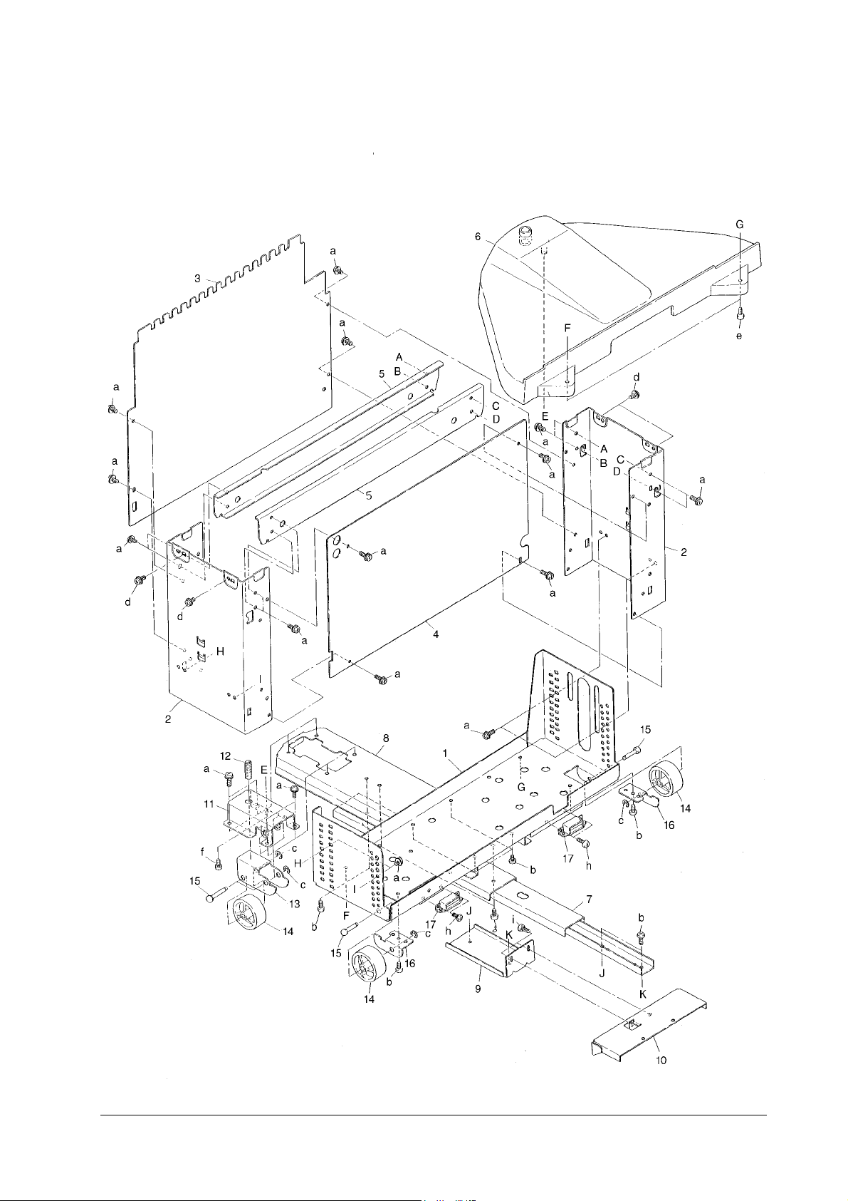
A-8 Base Assembly
A-19
SO-30
Page 55

Ref. No. Part code Description Remarks
08-H 5SNSASO30E39
08-01 5SNSP001 2714 BKT HEIGHT ADJUST
08-02 5SNSP0012715 FRAME KC
08-03 5SNSP0012729 PLATE COVER L
08-04 5SNSP0012730 PLATE COVER R
08-05 5SNSP0012716 REINFORCEMENT SIDE
08-06 5SNSP0012726 COVER CASTER
08-07 5SNSP0012725 RAIL
08-08 5SNS P0012723 FRAME ADJUST
08-09 5SNSP0012724 PLATE JOINT
08-10 5SNSP001 2741 BKT JOINT
08-11 5SNSP001 2722 BKT ADJUST CASTER
08-12 5SNSP001 2728 SCREW ADJUST
08-13 5SNSP0012719 PLATE
08-14 5SNSP0012720 ROLLER CASTER
08-15 5SNSP0012721 SHAFT CASTER
08-16 5SNSP0012717 PLATE
08-17 5SNSP001 2718 MAGNET CATCH
8-a 5MBTPX4006TZ BRAS. TAP SCREW
8-b 5SNSP0012588 M4X7 ROUNDED END
8-c 5MBCE4060XSP E STOP RING
8-d 5MBTPX4008TZ BRAS. TAP SCREW
8-e 5MBSPB4008NZ BIND HD SCREW
8-f 5SNSP0012727 SCR4X10 WAVE
8-g 5SNSP0012590 M4X9 ROUNDED END
8-h 5MBSPP4006NZ PAN HEAD SCREW
8-I 5MBSPB4008NN BIND HD SCREW
DOOR ASSEMBLY
SO-30
A-20
Page 56
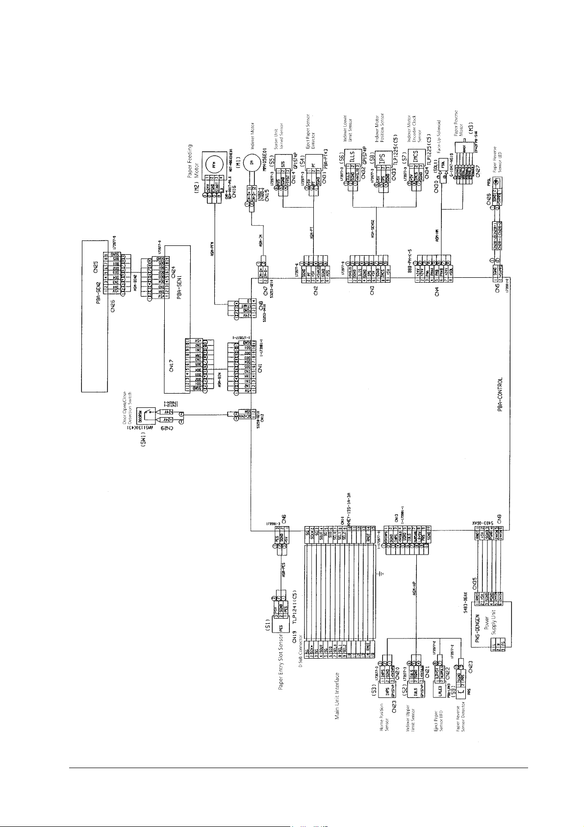
B-1 Wiring Diagram
A-21
SO-30
Page 57
 Loading...