

Page 1
Wide Format Printer
Operation Guide
Please read the Operation Guide before using the printer.
Keep it in the designated location for easy reference.
Page 2

As an ENERGY STAR Partner, KYOCERA MITA AMERICA, INC. has determined
that this product meets the ENERGY STAR guidelines for energy efficiency.
* ENERGY STAR is a U.S. registered mark.
NOTE
• This Operation Guide applies to models KM-P4845w and KM-P4850w. For the
purposes of this guide, KM-P4845w is a 2.6 ppm (prints per minute) printer (36" x
48" size) while KM-P4850w is a 3 ppm printer (36" x 48" size).
• This Operation Guide contains content for both the inch and metric specification
models of the printer. When messages displayed on the printer’s display differ only
in their capitalization, this guide uses the message from the inch specification model
of the printer. When there are other differences, the metric version of the message
is included in parentheses.
All rights reserved. No part of this material may be reproduced or transmitted in any
form or by any means, electronic or mechanical, including photocopying, recording
or by any information storage and retrieval system, without permission in writing from
the Publisher.
Legal Restriction On Copying
• It may be prohibited to copy copyrighted material without permission of the copyright
owner.
• It is prohibited under any circumstances to copy domestic or foreign currencies.
• Copying other items may be prohibited.
Page 3
Please read this Operation Guide before using the printer. Keep it close to the
printer for easy reference.
The sections of this guide and parts of the printer marked with symbols are safety warnings meant
to protect the user, other individuals and surrounding objects, and ensure correct and safe usage
of the printer. The symbols and their meanings are indicated below.
DANGER: Indicates that serious injury or even death will very possibly result from
insufficient attention to or incorrect compliance with the related points.
WARNING: Indicates that serious injury or even death may result from insufficient attention
to or incorrect compliance with the related points.
CAUTION: Indicates that personal injury or mechanical damage may result from insufficient
attention to or incorrect compliance with the related points.
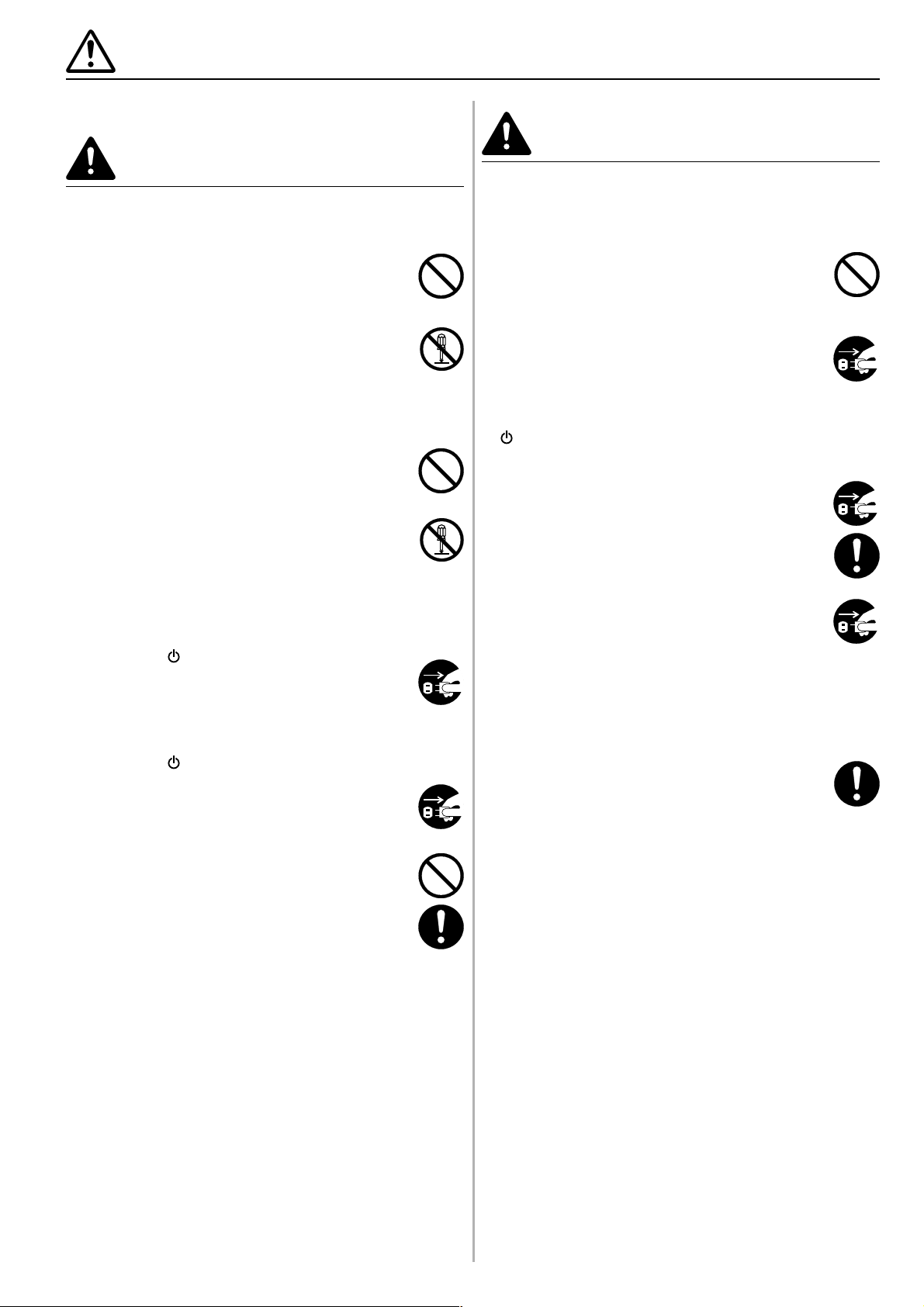
Symbols
The m symbol indicates that the related section includes safety warnings. Specific points of
attention are indicated inside the symbol.
................. [General warning]
................. [Warning of danger of electrical shock]
................. [Warning of high temperature]
The symbol indicates that the related section includes information on prohibited actions. Specifics
of the prohibited action are indicated inside the symbol.
.................. [Warning of prohibited action]
................... [Disassembly prohibited]
The ● symbol indicates that the related section includes information on actions which must be
performed. Specifics of the required action are indicated inside the symbol.
.................. [Alert of required action]
.................. [Remove the power plug from the outlet]
.................. [Always connect the printer to an outlet with a ground connection]
Please contact your service representative to order a replacement if the safety warnings in this
Operation Guide are illegible or if the guide itself is missing. (fee required)
Page 4

Trademark Information
• Microsoft, Windows, Windows NT and Internet Explorer are registered trademarks of Microsoft Corporation of America and other countries.
• WINDOWS ME is a trademark of Microsoft Corporation of America.
• Adobe, Acrobat and PostScript are registered trademarks of Adobe Systems Incorporated.
• Ethernet is a registered trademark of Xerox Corporation.
• IBM and IBM PC-AT are trademarks of International Business Machines Corporation of America.
• Macintosh, MacOS, AppleTalk and TrueType are registered trademarks of Apple Computer, Inc.
• HP-GL, HP-GL2 and HP-RTL are registered trademarks of Hewlett-Packard Company.
• AutoCAD is a registered trademark of Autodesk, Ltd.
All other company and product names contained in this Operation Guide are trademarks or registered trademarks of their respective companies.
The designations ™ and ® will not be used in this guide.
About This Operation Guide
There are two parts to this guide:
• Operation Guide (this booklet)
Contains explanations of content related to setup procedure, printer operation, configuration, and troubleshooting.
• Functions Edition (On-Line Manual)
Contains explanations on operation from your computer such as how to use related software applications.
The Functions Edition (On-Line Manual) is prepared as a PDF (Portable Document Format) file on the CD-ROM that is included with the printer.
Adobe Acrobat Reader 4.0 software is required in order to read this On-Line Manual.
i
Page 5
Reading the Functions Edition (On-Line Manual) for This Machine
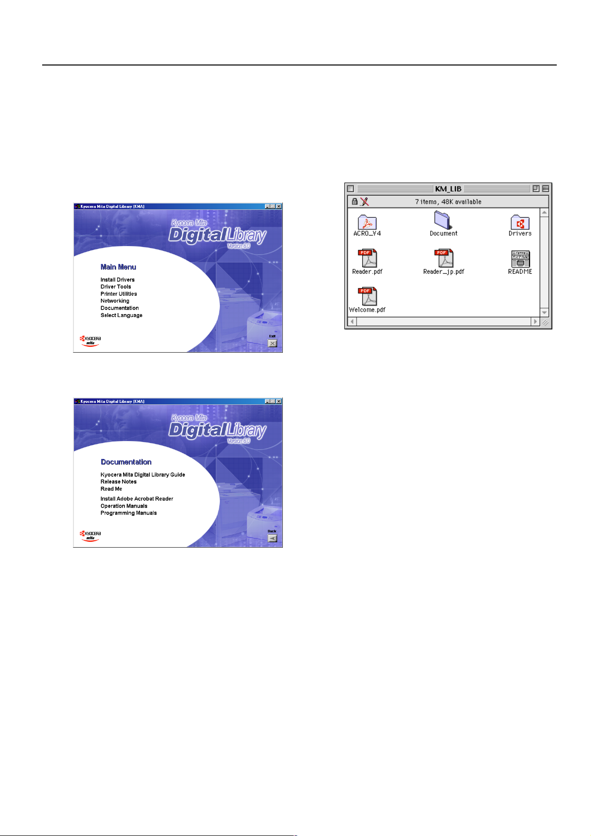
(1) Windows
1. Insert the CD-ROM that is included with the printer into the CDROM drive of your computer.
2. Click on [Documentation] under [Main Menu] on the left side of
the screen shown below.
* If this screen doesn’t appear after you insert the CD-ROM,
open the CD-ROM window to access its contents and doubleclick on the [setup.exe] file.
3. Click on [Operation Manuals] and then on [KM-P4845w/P4850w].
(2) Macintosh
1. Insert the CD-ROM that is included with the printer into the CDROM drive of your computer.
2. Double-click on the icon for the CD-ROM disk, and then doubleclick [Welcome.pdf] for the shown window. The Kyocera Mita
Digital Library screen will appear.
3. Click on [the available printer product name] for the shown
screen.
The selected printer’s Online Manual will appear.
4. Click on [Functions Manual]. Acrobat Reader will start up and the
Functions Edition (On-Line Manual) will open.
ii
Page 6
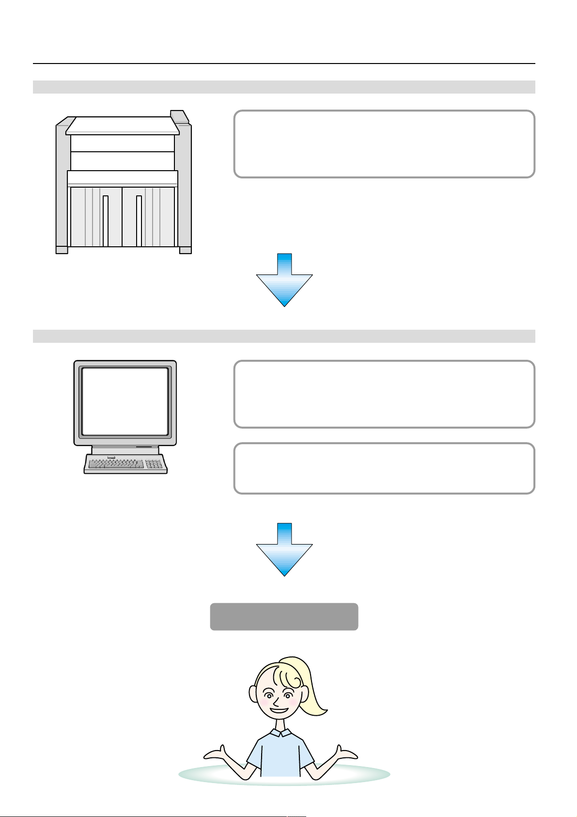
Setting Up the Printer
Configuring the Printer
Configuring Your Computer
1 Network Settings
[Configuring the IP Address, etc.] ....................... Page 3-2
Computer
2 Name Settings
[Changing the Computer (Device)
and Host Names] ................................................ Page 3-4
3 Installing the Printer Driver
(Refer to the Functions Editon [On-Line Manual].)
Printer Set-Up is Complete!
iii
Page 7

Options
■ <Roll unit>
To add a paper source.
■ <Key counter>
To count the number of sheets output.
■ <Scanner unit>
To use this machine as a scanner or a copier.
<System diagram with options installed>
Printer
Roll unit
Scanner unit
Key counter
iv
Page 8

Table of Contents
Trademark Information................................................ i
About This Operation Guide ....................................... i
Reading the Functions Edition (On-Line Manual) for
This Machine ......................................................... ii
Setting Up the Printer ................................................ iii
Options ......................................................................iv
CHAPTER 1
IMPORTANT! PLEASE READ FIRST. .1-1
CAUTION LABELS ....................................... 1-1
INSTALLATION PRECAUTIONS.................. 1-2
PRECAUTIONS FOR USE ........................... 1-3
CHAPTER 2
PRIOR TO SET-UP ................................2-1
1. Names of Parts .............................................. 2-1
(1) Main Body ......................................................... 2-1
(2) Operation Panel ................................................ 2-4
2. Included Software .......................................... 2-5
3. Required Items............................................... 2-5
4. Energy Saver Function .................................. 2-6
6. Auto Shutoff Function .................................... 2-6
CHAPTER 5
MANAGEMENT AND SETTING............5-1
1. Machine Default ............................................. 5-1
(1) List of Machine Settings .................................... 5-1
(2) Configuring Machine Setting ............................. 5-4
2. Printer Settings ............................................ 5-11
(1) List of Printer Settings ..................................... 5-11
3. Language Switching ..................................... 5-12
CHAPTER 6
TROUBLESHOOTING .......................... 6-1
1. If One of These Messages is Displayed... ..... 6-1
2. Replenishing the Toner .................................. 6-3
3. Replacing the Waste Toner Tank ................... 6-5
4. Countermeasures against Call for service
Message ........................................................ 6-6
5. When Paper Jams ......................................... 6-7
(1) Jam Location Display ........................................ 6-7
(2) Cautions ............................................................ 6-7
(3) Removal Procedure .......................................... 6-7
6. Troubleshooting ........................................... 6-11
CHAPTER 3
GETTING READY FOR PRINTING.......3-1
1. Setup .............................................................. 3-1
(1) System Configuration ........................................ 3-1
(2) Procedures ........................................................ 3-2
2. Paper ............................................................. 3-6
(1) Paper Type ........................................................ 3-6
(2) How to Set a Paper Roll .................................... 3-7
(3) Dew prevention heater ...................................... 3-9
(4) How to Use the Paper Tray Support Plate ........ 3-9
CHAPTER 4
PRINTER OPERATION .........................4-1
1. Basic printing ................................................. 4-1
2. Printing with manually fed media ................... 4-2
3. Making a Test Print ........................................ 4-3
4. Canceling Printing .......................................... 4-4
5. Resetting the printer ....................................... 4-5
CHAPTER 7
SPECIFICATIONS .................................7-1
v
Page 9

CHAPTER 1 IMPORTANT!
PLEASE READ FIRST.
CAUTION LABELS
Caution labels have been attached to the printer at the following locations for safety purposes.
BE SUFFICIENTLY CAREFUL to avoid fire or electric shock when removing a paper jam.
Label 1
High temperature inside. Do not touch
parts in this area, because there is a
danger of getting burned.....................
Label 2 (Inch specification only)
High temperature inside. Do not touch
parts in this area, because there is a
danger of getting burned.....................
Label 3
High temperature inside. Do not touch
parts in this area, because there is a
danger of getting burned.....................
Label 4
High temperature inside. Do not touch
parts in this area, because there is a
danger of getting burned.....................
Label 5, 6, 7
High voltage inside. NEVER touch
parts in this area, because there is a
danger of electric shock. ....................
NOTE: DO NOT remove these labels.
1-1
Page 10

INSTALLATION PRECAUTIONS
■ Environment
CAUTION
• Avoid placing the printer on or in locations which
are unstable or not level. Such locations may
cause the printer to fall down or fall over. This
type of situation presents a danger of personal
injury or damage to the printer. ............................
• Avoid locations with humidity or dust and dirt. If
dust or dirt become attached to the power plug,
clean the plug to avoid the danger of fire or
electrical shock.....................................................
• Avoid locations near radiators, heaters, or other
heat sources, or locations near flammable items,
to avoid the danger of fire. ...................................
• To keep the printer cool and facilitate changing of
parts and maintenance, allow access space as
shown below.
Leave adequate space, especially around the left
right and rear covers, to allow air to be properly
ventilated out of the printer. ..................................
Rear:
>
11 13/16"
=
Left:
>
11 13/16"
=
30 cm
Front:
>
31 1/2"
=
80 cm
• Always use the caster stoppers to stabilize the
printer once it is in place to keep it from moving
and/or falling over and causing injury. ..................
Other precautions
• Adverse environmental conditions may affect the safe
operation and performance of the printer. Install in an
air-conditioned room (recommended room temperature:
around 68°F [20°C], humidity: around 65%RH) and
avoid the following locations when selecting a site for
the printer.
.
Avoid locations near a window or with exposure to
direct sunlight.
.
Avoid locations with vibrations.
.
Avoid locations with drastic temperature fluctuations.
.
Avoid locations with direct exposure to hot or cold air.
.
Avoid poorly ventilated locations.
30 cm
Right:
>
19 11/16"
=
50 cm
• If the floor is delicate against casters, when this product
is moved after installation, the floor material may be
damaged.
• During printing, some ozone is released, but the amount
does not cause any ill effect to one's health. If, however,
the printer is used over a long period of time in a poorly
ventilated room or when making an extremely large
number of copies, the smell may become unpleasant.
To maintain the appropriate environment for printing
work, it is suggested that the room be properly
ventilated.
■ Power supply/Grounding the printer
WARNING
• DO NOT use a power supply with a voltage other
than that specified. Avoid multiple connections in
the same outlet. These types of situations
present a danger of fire or electrical shock. .........
• Plug the power cord securely into the outlet. If
metallic objects come in contact with the prongs
on the plug, it may cause a fire or electric shock.
• Always connect the printer to an outlet with a
ground connection to avoid the danger of fire or
electrical shock in case of an electric short. If an
earth connection is not possible, contact your
service representative. .........................................
Other precautions
• Connect the power plug to the closest outlet possible to
the printer.
• The power supply cord is used as the main disconnect
device. Ensure that the socket/outlet is located/installed
near the equipment and is easily accessible.
■ Handling of plastic bags
WARNING
• Keep the plastic bags that are used with the
printer away from children. The plastic may cling
to their nose and mouth causing suffocation........
1-2
Page 11
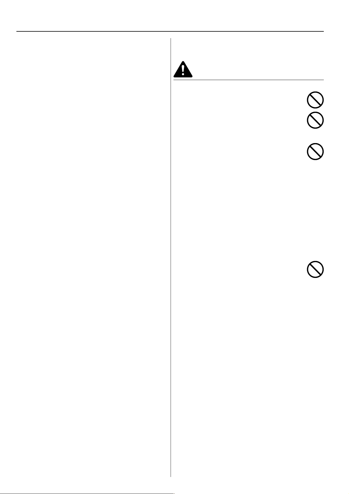
PRECAUTIONS FOR USE
■ Cautions when using the printer
WARNING
• DO NOT place metallic objects or containers with
water (flower vases, flower pots, cups, etc.) on or
near the printer. This type of situation presents a
danger of fire or electrical shock should they fall
inside. ...................................................................
• DO NOT remove any of the covers from the
printer as there is a danger of electrical shock
from high voltage parts inside the printer. ............
• DO NOT damage, break or attempt to repair the
power cord. DO NOT place heavy objects on the
cord, pull it, bend it unnecessarily or cause any
other type of damage.
These types of situations present a danger of fire
or electrical shock. ...............................................
• NEVER attempt to repair or disassemble the
printer or its parts as there is a danger of fire,
electrical shock or damage to the laser................
• If the printer becomes excessively hot, smoke
appears from the printer, there is an odd smell, or
any other abnormal situation occurs, there is a
danger of fire or electrical shock. Turn the main
switch OFF ( ) immediately, remove the power
plug from the outlet and contact your service
representative. .....................................................
• If anything harmful (paper clips, water, other
fluids, etc.) falls into the printer, turn the main
switch OFF ( ) immediately. Next, remove the
power plug from the outlet to avoid the danger of
fire or electrical shock. Then contact your service
representative. .....................................................
CAUTION
• DO NOT pull the power cord when removing it
from the outlet. If the power cord is pulled, the
wires may become broken and there is a danger
of fire or electrical shock. (ALWAYS grasp the
power plug when removing the power cord from
the outlet.) ............................................................
• ALWAYS remove the power plug from the outlet
when moving the printer. If the power cord is
damaged, there is a danger of fire or electrical
shock. ...................................................................
• If the printer will not be used for a short period of
time (overnight, etc.), turn the main switch OFF
( ).
If it will not be used for an extended period of
time (vacations, etc.), remove the power plug
from the outlet for safety purposes during the
time the printer is not in use. ................................
• When moving the printer, turn the leveler bolts to
keep them away from the floor. ............................
• For safety purposes, ALWAYS remove the power
plug from the outlet when performing cleaning
operations. ...........................................................
• If dust accumulates within the printer, there is a
danger of fire or other trouble. It is therefore
recommended that you consult with your service
representative in regard to cleaning of internal
parts. This is particularly effective if accomplished
prior to seasons of high humidity. Consult with
your service representative in regard to the cost
of cleaning the internal parts of the printer. ..........
• DO NOT remove or connect the power plug with
wet hands, as there is a danger of electrical
shock. ...................................................................
• ALWAYS contact your service representative for
maintenance or repair of internal parts. ...............
1-3
Page 12
PRECAUTIONS FOR USE
Other precautions
• DO NOT place heavy objects on the printer or cause
other damage to the printer.
• DO NOT open the front cover, turn off the main switch,
or pull out the power plug during printing.
• When lifting or moving the printer, contact your service
representative.
• Do not touch electrical parts, such as connectors or
printed circuit boards. They could be damaged by static
electricity.
• DO NOT attempt to perform any operations not
explained in this handbook.
• CAUTION : Use of controls or adjustments or
performance of procedures other than those specified
herein may result in hazardous radiation exposure.
■ Cautions when handling
consumables
CAUTION
• DO NOT attempt to incinerate the toner
containers or the waste toner tank. Dangerous
sparks may cause burns. .....................................
• Keep the toner containers and the waste toner
tank out of the reach of children...........................
• If toner happens to spill from the toner containers
or the waste toner tank, avoid inhalation and
ingestion, as well as contact with your eyes and
skin. ......................................................................
.
If you do happen to inhale toner, move to a
place with fresh air and gargle thoroughly with a
large amount of water. If coughing develops,
contact a physician.
.
If you do happen to ingest toner, rinse your
mouth out with water and drink 1 or 2 cups of
water to dilute the contents of your stomach. If
necessary, contact a physician.
.
If you do happen to get toner in your eyes, flush
them thoroughly with water. If there is any
remaining tenderness, contact a physician.
.
If toner does happen to get on your skin, wash
with soap and water.
• DO NOT attempt to force open or destroy the
toner containers or the waste toner tank. .............
Other precautions
• After use, ALWAYS dispose of the toner containers and
the waste toner tank in accordance with Federal, State
and Local rules and regulations.
• Store all consumables in a cool, dark location.
• If you will not be using the printer for a prolonged period
of time, remove all paper from the drawer(s) and the
multi-bypass tray and seal in its original packaging.
1-4
Page 13
CHAPTER 2 PRIOR TO SET-UP
1. Names of Parts
4
5
7
8
3
123 6 6
4
0
!
@
89
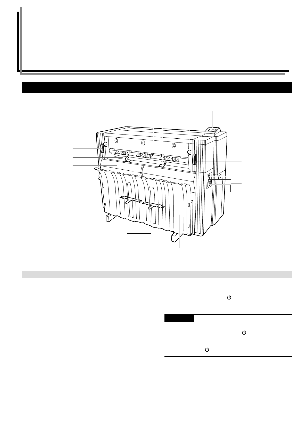
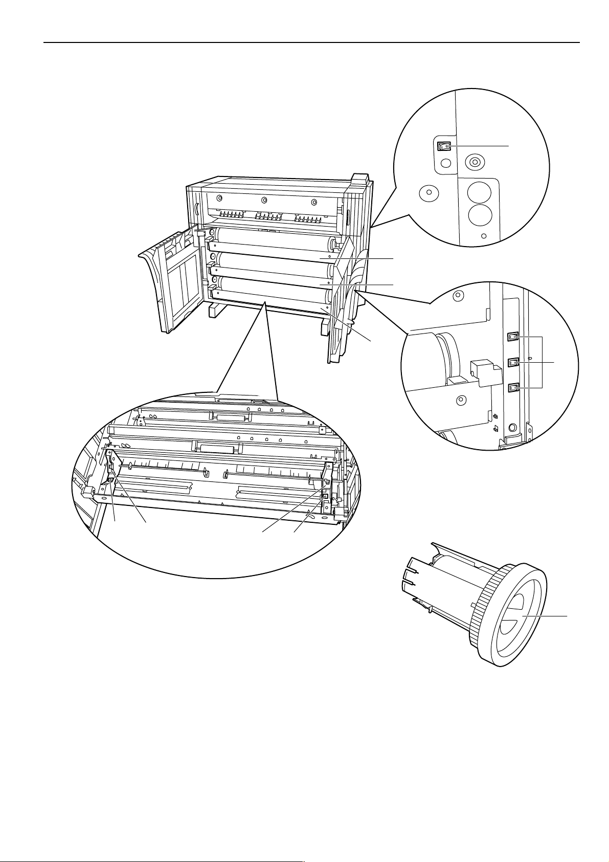
(1) Main Body
1 Operation panel
Use to make settings in the printer.
2 Ejection cover
Open in case of a paper jam.
3 Ejection release lever
Operate this lever in case of a paper jam.
4 Printer body release lever
Operate this lever in case of a paper jam.
5 Bypass table
When printing documents and using the manual paper feed
setting, set paper onto on this table.
6 Bypass guide
7 Front cover
Open to set paper roll or in case of a paper jam.
8 Paper tray
Printed sheets will be stored here.
9 Paper tray support plate
Set in accordance with paper size.
0 Main switch
Turn this switch ON ( | ) in order to use the printer. Conversely,
make sure this switch is OFF ( ) before connecting network
cables.
IMPORTANT
• Once you turn the main switch ON ( | ) wait for at least 20 seconds
or so before attempting to turn it OFF ( ) again. Failure to doing
so may damage the printer.
• Make sure that you wait at least for 5 seconds after turned the
main switch OFF ( ) to remove the power plug from the outlet.
! Total counter
This indicates the paper output length.
@ Key counter insert slot
When a key counter (option) is installed, insert the key counter
here.
2-1
Page 14
CHAPTER 2 PRIOR TO SET-UP
^
%
¤
⁄
$
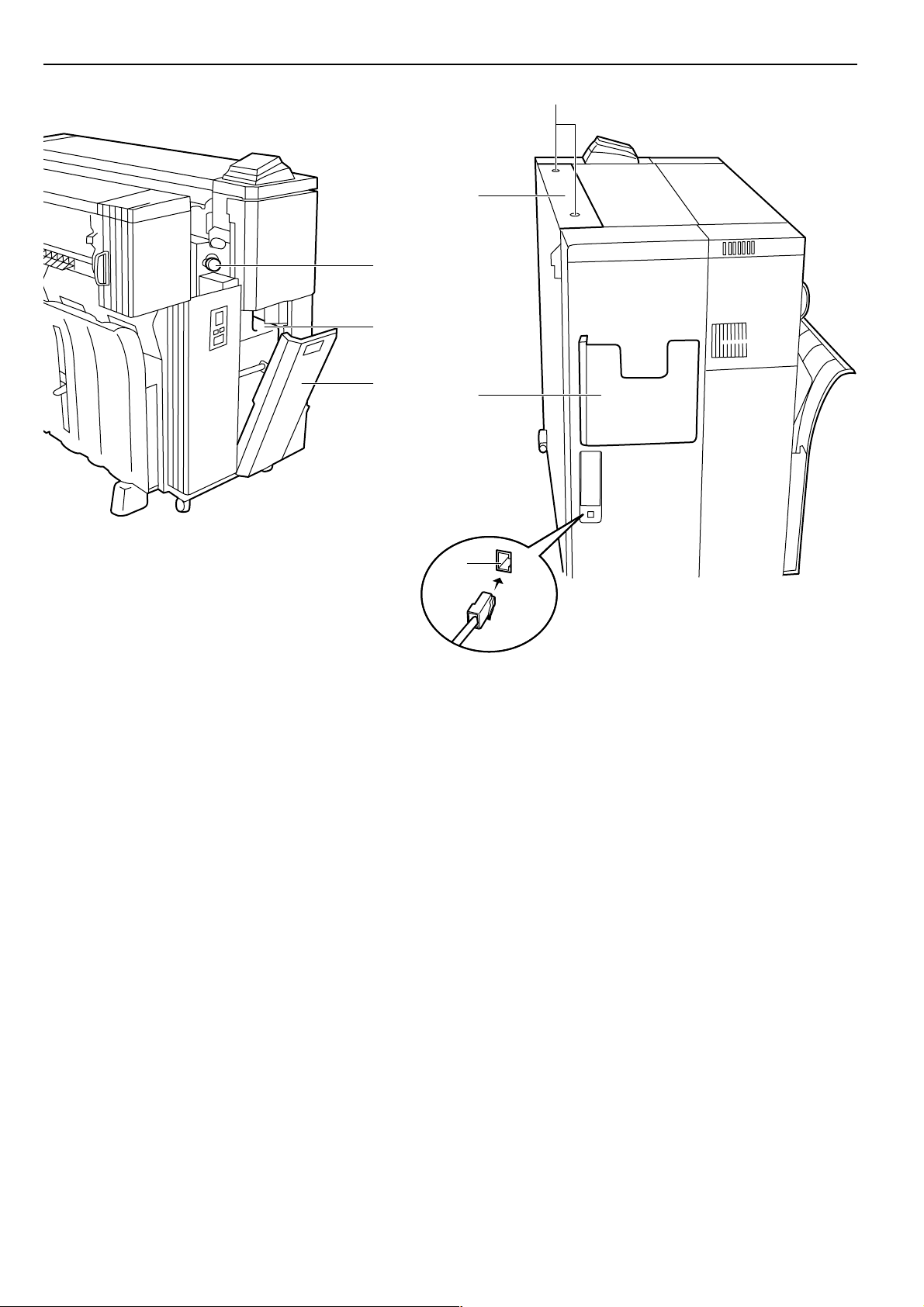
# Network interface connector
Use to connect the printer to the LAN (Local Area Network) with a
10BASE-T or 100BASE-TX cable.
$ Right cover
Open to replace the waste toner tank.
% Toner replenishing slot
Open to add toner.
^ Toner replenishing slot screw
Turn to open the toner replenishing slot.
& Roll unit (paper source 1: option)
* Roll unit (paper source 2)
( Roll unit (paper source 3)
) Operation Guide box
Keep the Operation Guide here.
)
#
⁄ Waste toner tank
¤ Paper transport knob
Operate this knob in case of a paper jam.
‹ Dew prevention heater switches
Switches for paper sources 1, 2, and 3.
› Main heater switch
If this switch is turned off, the dew prevention heaters will be
turned off even if the dew prevention heater switches inside the
front cover are on.
fi Flanges
Set these on both sides of the paper roll.
fl Release levers
‡ Flange guides
2-2
Page 15
CHAPTER 2 PRIOR TO SET-UP
&
*
(
‹
›
fl
fl
‡
‡
fi
2-3
Page 16
CHAPTER 2 PRIOR TO SET-UP
5
6
1
2 3 4
@
#
$
%
7
^
8
99
0!
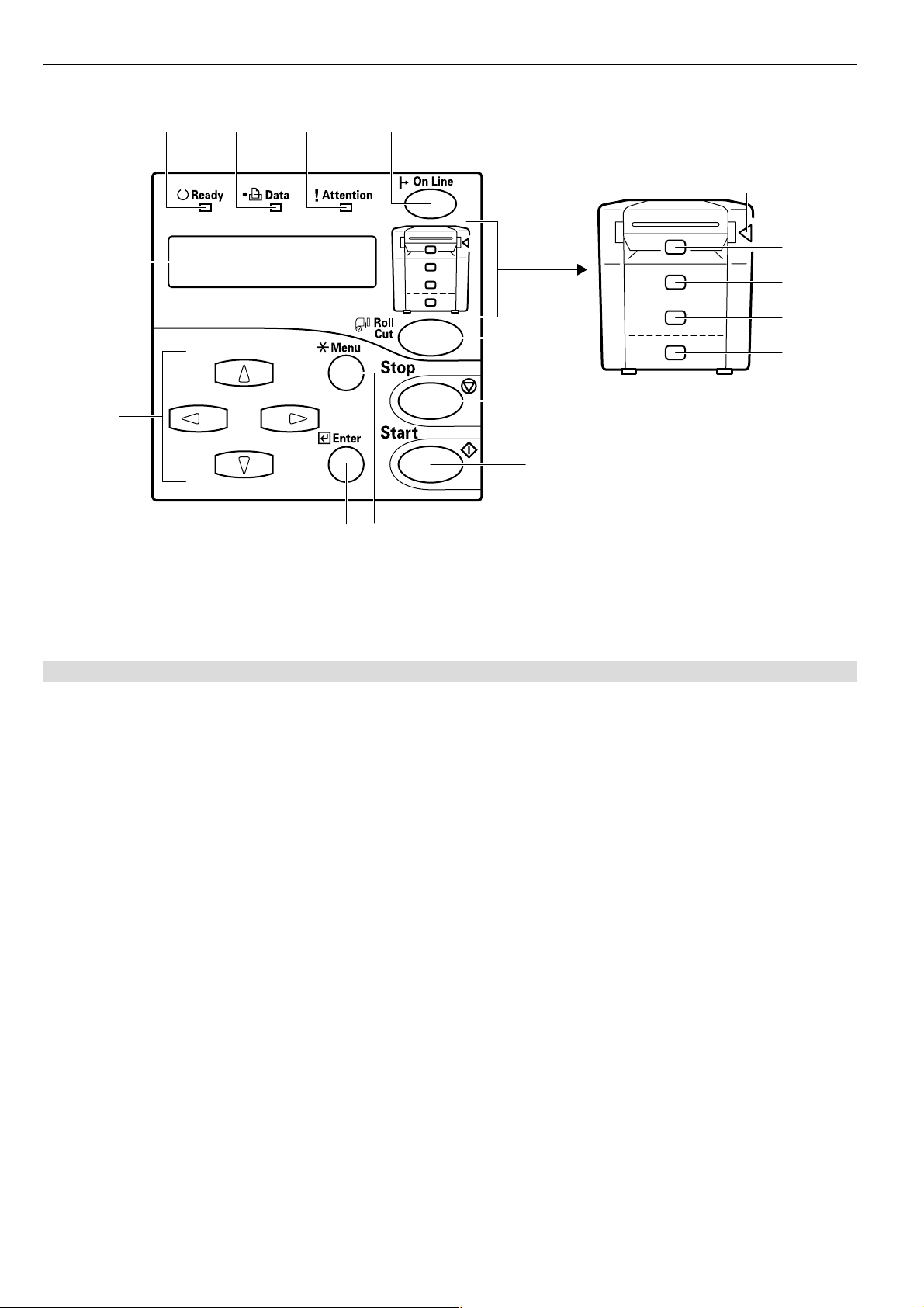
(2) Operation Panel
1 Ready indicator
This indicator is lit when the printer is on-line and goes out when it
is off-line. In addition, the indicator flashes while the internal server
computer is starting up.
2 Data indicator
This indicator flashes during printing.
3 Attention indicator
This indicator is lit when an error has occurred.
4 On Line key
Press this key when you want to switch the printer on- and off-line.
5 Message display
Machine status and errors are indicated on the message display.
6 MNOP Cursor keys
Use these cursor keys in order to select the various setting modes.
In addition, the N or M key may be used to select a paper tray.
7 Roll Cut key
Press this key when a new paper roll is set. Also press to force a
roll cut during output and to cancel printing.
8 Stop key
This key is used to cancel printing as well as in the configuration of
some settings to clear entered values.
9 Start key
Press this key to print to the currently set paper roll when the print
data’s page size and/or media type do not match those of the
current roll.
0 Enter key
Press this key when you want to register a setting. The Enter key
is also used to return to the printer to standard mode from energy
saver or sleep mode (Page 2-6).
! */Menu key
Press this key to configure the printer’s settings and output test
prints. (When the */Menu key has been pressed and one of the
printer setting screens is being displayed, the Ready indicator will
go out and the printer will be off-line.)
@ Internal paper jam indicator
This indicator is lit when a paper jam has occurred inside the
printer.
# Manual feed indicator
This indicator is lit when the manual feed has been selected and
when a paper jam has occurred in the manual feed mechanism.
$ Paper tray 1 indicator
This indicator is lit when the optional roll unit has been installed
and paper tray 1 has been selected, as well as when a paper jam
has occurred in paper tray 1.
% Paper tray 2 indicator
This indicator is lit when paper tray 2 has been selected as well as
when a paper jam has occurred in paper tray 2.
^ Paper tray 3 indicator
This indicator is lit when paper tray 3 has been selected as well as
when a paper jam has occurred in paper tray 3.
2-4
Page 17

2. Included Software
CHAPTER 2 PRIOR TO SET-UP
The following software can be found on the CD-ROM that is included
with the printer.
NOTE
Refer to the Functions Edition (On-Line Manual) for the procedures
for installing these printer drivers and utilities.
• Printer drivers
Printer drivers are included so that you can use the printer.
The printer drivers are compatible for use with the following operating
systems: Windows 95/98/Me, Windows NT 4.0, and Windows 2000.
• Printer drivers (for AutoCAD)
A printer driver compatible for use with AutoCAD2000i/2000/Release
14 is included.
• Macintosh PPD file
A PPD (PostScript Printer Description) file is included so that you can
use the printer with a Macintosh computer.
• Print Utility
A Print Utility is included so that you can select a file to be printed
without the need to open the corresponding application. (Up to 30 files
can be selected at one time.)
The Print Utility is compatible for use with the following file formats:
HP-GL, HP-GL2, HP-RTL, Calcomp906/PCI, Calcomp907/PCI,
CALS_G4 (TIFF 6.0), DXF (AutoCAD standard, some settings
restricted), TIFF, JPEG, BMP, DGN (optional) and CGM (optional)
The Print Utility is compatible for use with the following operating
systems: Windows 95/98/Me, Windows NT 4.0, and Windows 2000
• KM-NET VIEWER
The KM-NET VIEWER is included so that you can manage a printer
over the network from your computer.
• Functions Edition (On-Line Manual)
The Functions Edition (On-Line Manual) is prepared as a PDF
(Portable Document Format) file. Read the Functions Edition together
with this Operation Guide. Adobe Acrobat Reader 4.0 must be
installed in your computer in order to read the Functions Edition (OnLine Manual).
• Adobe Acrobat Reader
Acrobat Reader 4.0 is included so that you can read and print the
Functions Edition (On-Line Manual).
3. Required Items
The following items are not included with the printer and must be
purchased separately.
• Network cable
(Twisted-pair 10BASE-T or 100BASE-TX [category 5])
NOTE
Be sure to use a “shielded type” network cable.
• Network hub
2-5
Page 18
CHAPTER 2 PRIOR TO SET-UP
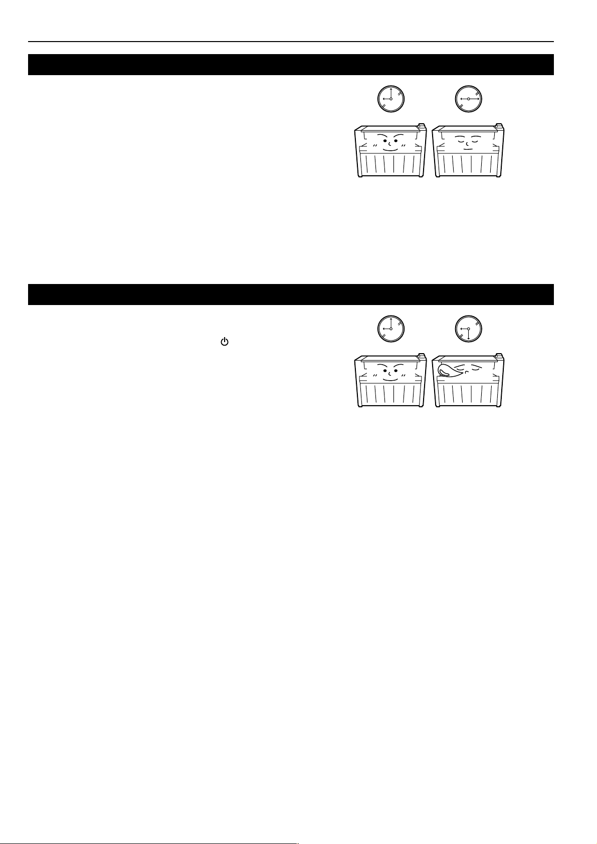
4. Energy Saver Function
The automatic energy saver function automatically sets the printer to
a low energy consumption mode when the printer has not been used
for a specific period of time. When in energy saver mode the
message “Pre heating” [“Now preheating”] will be displayed.
Upon detection of a print signal from the computer, the printer
automatically returns to its standard mode and starts printing.
Pressing the Enter key will also cause the printer to return to standard
mode. The time until the energy saver function activates (auto energy
saver time) is set to a factory default of 15 min. This value can be set
in the machine setting “6. Timer set” from 5 to 45 min., in 5 min.
increments (Page 5-7).
5. Auto Shutoff Function
The auto shutoff function consists of shutoff mode and sleep mode.
The factory default is set to sleep mode.
• Shutoff mode: Power is automatically turned OFF ( ) when the
printer has not been used for a specific period of time.
To return to normal operation from shut-off mode, turn ON ( | ) the
main switch.
• Sleep mode: The printer enters a sleep state when it has not been
used for a specific period of time. The message “Sleeping” will be
displayed when the printer is in sleep mode.
Upon detection of a print signal from the computer, the printer
automatically wakes up and starts printing. Pressing the Enter key
will also cause the printer to wake up.
The auto shut-off function can be configured in the machine setting “5.
Auto shutoff” (Page 5-7). The time until the auto shutoff feature
activates (auto shutoff time) is set to a factory default of 90 min. This
value can be set in the machine setting “6. Timer set” from 15 to 120
min., in 5 min. increments (Page 5-7).
2-6
Page 19
CHAPTER 3 GETTING READY FOR
PRINTING
1. Setup
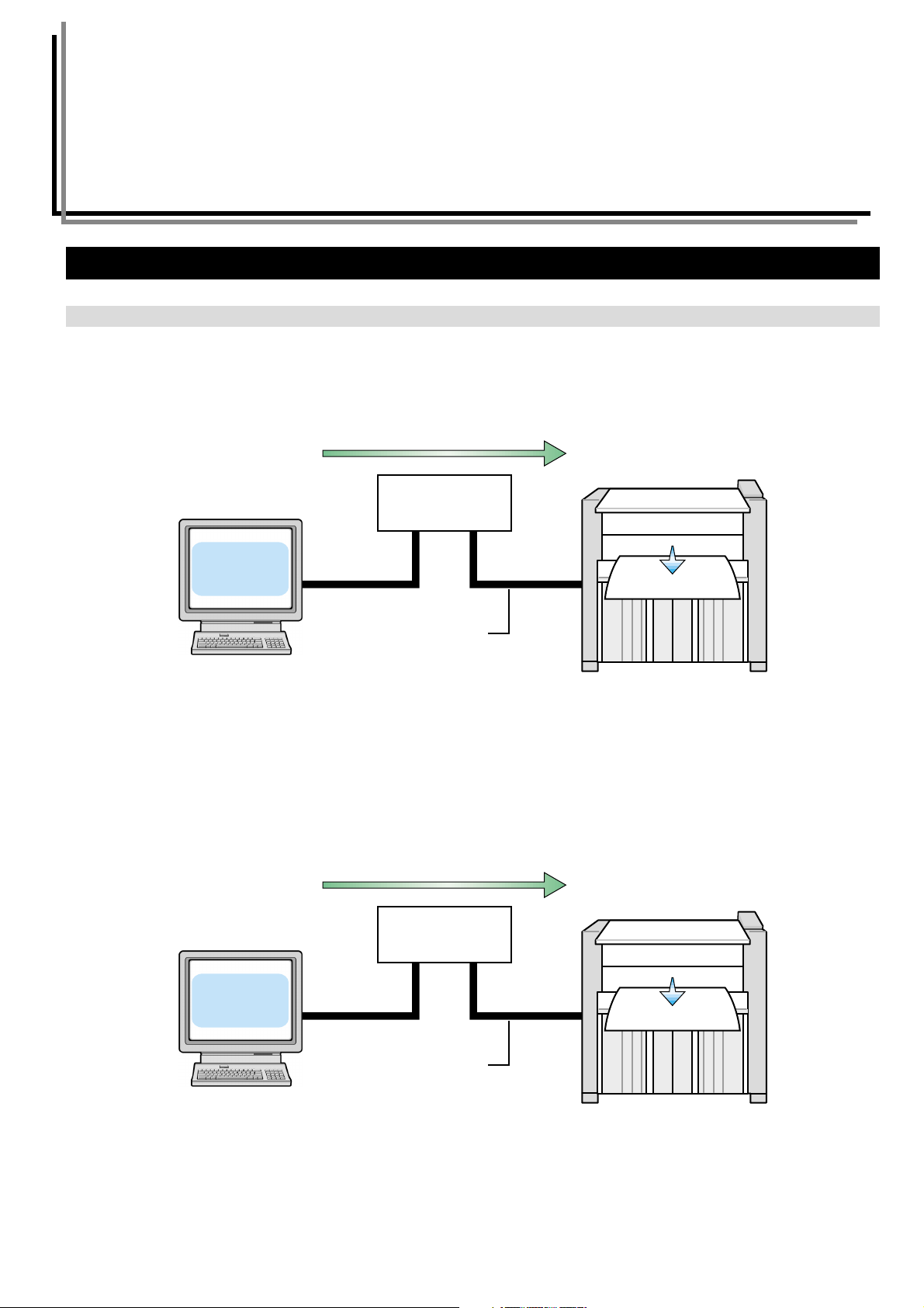
(1) System Configuration
● Printing from Windows
Print command
Network hub
Printer driver
Printout
Computer
● Printing from Macintosh
LaserWriter 8
PPD file
100BASE-TX
(or 10BASE-T) cable
Print command
Network hub
Printout
100BASE-TX
(or 10BASE-T) cable
Computer
3-1
Page 20
CHAPTER 3 GETTING READY FOR PRINTING
(2) Procedures
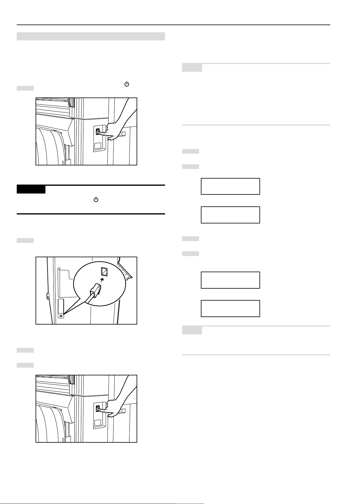
● Connecting the Printer to Your Network
Perform this procedure in order to connect the printer to the network
hub.
Turn the main switch on the printer OFF ( ).
1
CAUTION
Make sure the main switch is OFF ( ) before connecting the
network cable.
● Network Settings [Configuring the IP Address, etc.]
Perform this procedure in order to register the required network
settings.
NOTE
• The IP address to be used for the printer will differ depending upon
your network. Confirm the address that you need to use in advance
with your network manager.
• If you will use a DHCP server to designate the IP address, there is
no need to perform the following procedure because the factory
default for the printer is set for DHCP server configuration.
• The “*” in a list of setting options indicates the current setting.
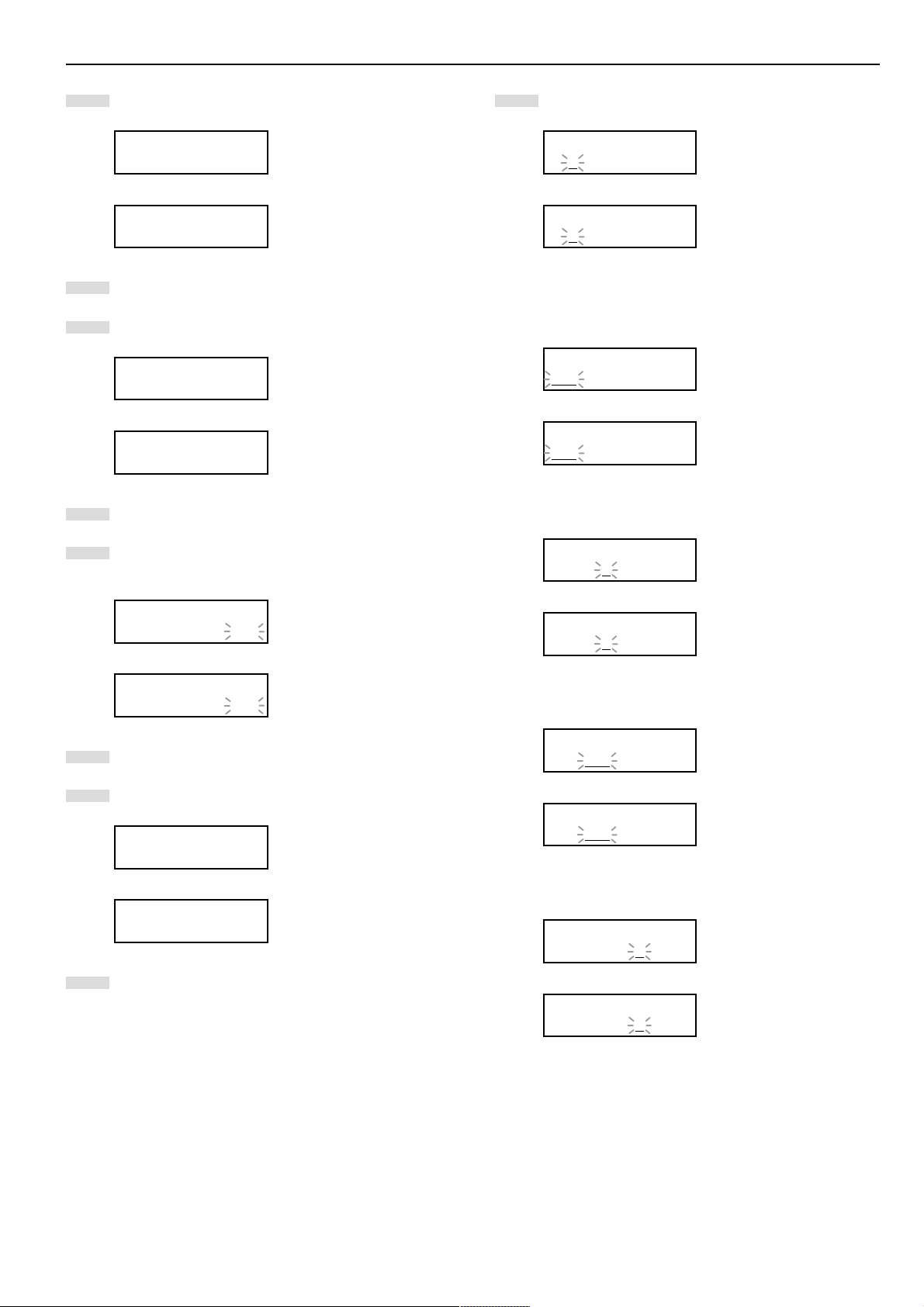
Press the */Menu key.
1
Press the N or M key to select “3. Set/manager”.
2
Inch specifications
Menu:
3.Set/manager
Metric specifications
Menu:
3.Set/manager
Plug the network cable into the Network Interface Connector
2
which is located on the left side of the printer.
Plug the other end of the network cable into the network hub.
3
Turn the main switch on the printer back ON ( | ).
4
Press the Enter key.
3
Use the MNOP cursor keys to input the pin code (the
4
default setting is qQrR).
Inch specifications
Enter pin code.
_ _ _ _
Metric specifications
Enter pin code.
_ _ _ _
NOTE
The pin code may be changed (see “13. Mgr. code change” on page
5-10).
3-2
Page 21
CHAPTER 3 GETTING READY FOR PRINTING
Press the N or M key to select “2. Set printer”.
5
Inch specifications
Set/manager:
2.Set printer
Metric specifications
Set/manager:
2.Set printer
Press the Enter key.
6
Press the N or M key to select “3. DHCP server”.
7
Inch specifications
Set printer:
3.DHCP server
Metric specifications
Set printer:
3.DHCP server
Press the Enter key.
8
The selected item will flash. Press the N or M key to select
9
“OFF”.
Inch specifications
DHCP server:
OFF
Metric specifications
DHCP server:
OFF
Press the Enter key.
10
Press the N or M key to select “4. IP address”.
11
Inch specifications
Set printer:
4.IP address
Metric specifications
Set printer:
4.IP address
Press the Enter key.
12
Use the MNOP cursor keys to input the IP address.
13
Inch specifications
IP address:
0. 0. 0. 0
Metric specifications
IP address:
0. 0. 0. 0
In order to set the IP address to “192.168.0.1”, perform the
following procedure.
1 Press the N or M key to display “192”.
Inch specifications
IP address:
192. 0. 0. 0
Metric specifications
IP address:
192. 0. 0. 0
2 Press the P key. The next value will flash.
Inch specifications
IP address:
192. 0. 0. 0
Metric specifications
IP address:
192. 0. 0. 0
3 Press the N or M key to display “168”.
Inch specifications
IP address:
192.168. 0. 0
Metric specifications
IP address:
192.168. 0. 0
4 Press the P key. The next value will flash.
Inch specifications
IP address:
192.168. 0. 0
Metric specifications
IP address:
192.168. 0. 0
3-3
Page 22

CHAPTER 3 GETTING READY FOR PRINTING
5 Press the P key. The next value will flash.
Inch specifications
IP address:
192.168. 0. 0
Metric specifications
IP address:
192.168. 0. 0
6 Press the N or M key to display “1”.
Inch specifications
IP address:
192.168. 0. 1
Metric specifications
IP address:
192.168. 0. 1
NOTE
Press the Stop key if you want to enter the address once again from
the beginning. The displayed IP address will return to its previous
value.
Press the Enter key.
14
Use the same procedure in order to set the “5. Subnet
15
mask”, “6. Gateway”, and “7. WINS server” information.
Once you have completed all of the required settings, press
16
the N or M key to select “End” and then press the Enter key.
Inch specifications
Set printer:
End
Press the N or M key to select “End” and press the Enter
18
key.
Inch specifications
Menu:
End
Metric specifications
Menu:
End
● Name Settings [Changing the Computer (Device) and
Host Names]
Perform this procedure in order to register the required name settings
[the computer (device) name and host name]. The Web Manager
interface is utilized to make these settings.
NOTE
• Since there is a danger of communications trouble occurring if
another computer on your network is using the same computer
name, be sure to consult with your network manager in advance
when selecting the name that you want to use for the printer.
• Be sure to use the same name for both the printer's computer
(device) name and host name.
• Use the Internet Explorer browser application on another client
computer in order to access the Web Manager interface.
• In order to use the Web Manager interface it is necessary to register
the correct IP address in the printer in advance. Refer to “● Network
Settings [Configuring the IP Address, etc.]” on page 3-2.
• While this section only explains how to set the computer (device)
name and host name using the Web Manager interface, Web
manager is convenient for a number of uses. Refer to the Functions
Edition (On-Line Manual) or the Help icon in the Web Manager
interface for more detailed information.
Start up a client computer that can access the printer over
1
the network.
17
3-4
Metric specifications
Set printer:
End
Press the N or M key to select “End” [“back”] and press the
Enter key.
Inch specifications
Set/manager:
End
Metric specifications
Set/manager:
back
Run Internet Explorer on that computer.
2
Enter the following URL:
3
http://<IP address of the printer>/
NOTE
The current IP address can be verified in the “● Network Settings
[Configuring the IP Address, etc.]” procedure on page 3-2.
The login screen will appear. Enter “Administrator” for the
4
user name and click on [OK].
Once you have logged on successfully, the Web Manager
5
wizard will appear. Click on [Kyocera Mita Wide format Web
Manager] at the bottom of the wizard screen.
Page 23

Click on [System] in the icons on the left side of the Web
6
Manager interface.
Click on the [Server Setting] tab in the [System] screen to
7
view the contents of that tab.
CHAPTER 3 GETTING READY FOR PRINTING
Click on the [Network Setting] button to display the [Network
8
Configuration] screen.
Enter the appropriate information in the [Computer Name]
9
and [Host Name] fields.
NOTE
Be sure to enter the same information in both the [Computer Name]
and [Host Name] fields.
Click on the [Enter] button to complete configuration of the
10
computer (device) name and host name.
3-5
Page 24

CHAPTER 3 GETTING READY FOR PRINTING
2. Paper
(1) Paper Type
Note the following restrictions on paper that can be used in this
machine.
● Compatible paper
1. Paper source 1 (option), paper source 2, and paper source 3
• Paper roll width: 17" to 36" [210 to 920 mm]
• Paper roll outer diameter: 6 3/4" [180 mm] or less
• Paper roll inner diameter: 3" [76 mm (75.2 to 77.2 mm)]
• Acceptable paper roll types
Plain paper (64 to 80 g/m2)
Vellum
Film
2. Bypass
• Paper sizes (standard paper): 8 1/2" x 11" to 36" x 48"
[A4 portrait to A0]
• Paper width: 8 1/2" to 36" [210 to 920 mm]
• Paper length: 11" to 48" [297 to 1189 mm]
• Acceptable paper materials
Plain paper (64 to 80 g/m2)
Vellum
Film
● Unacceptable paper
• Paper other than the paper described in “● Compatible paper”
• Paper with staples, etc.
• If paper is wrinkled, folded or broken, unroll the paper until the
problem disappears and cut the paper before using it.
● Automatic paper width detection
If the paper roll that has been set is of a standard size, the paper
width will be automatically detected. The following sizes can be
detected.
Inch specifications
<Architecture>
36"
24"
18"
12"
9"
<Engineering>
34"
22"
17"
11"
8 1/2"
NOTE
• Automatic detection will not function for the bypass.
• Paper width of non-standard sizes can be registered. See “1. Paper
width” in the default setting. (Page 5-6)
• For switching between standard sizes (architecture/engineering [A
sizes/ B sizes]), see “10. Standard size” in the default settings.
(Page 5-9)
Metric specifications
<A sizes>
A0: 841mm
A1: 594mm
A2: 420mm
A3: 297mm
A4: 210mm
<B sizes>
B1: 728mm
B2: 515mm
B3: 364mm
B4: 257mm
● Storage of paper
If the machine is not used for an extended period time, remove the
paper roll and return it to its original packaging and reseal it.
IMPORTANT
• Vellum
Since vellum is very susceptible to its environment, when it is not
used, put it in a plastic bag and seal it.
• When using vellum at a high humidity or at a low temperature,
vellum will become fragile, resulting in wrinkles prints or missing
images. If images are not properly printed, perform the following
procedure.
* When using cut vellum:
Change the orientation of the paper (portrait or landscape).
* When using a vellum roll:
Unroll 1 length of paper and cut the paper before using it.
• When using roll paper whose surface is contaminated with
adhesive, remove the adhesive or unroll the paper until the adhesive
is no longer visible and cut off the unusable length.
3-6
Page 25

CHAPTER 3 GETTING READY FOR PRINTING
(2) How to Set a Paper Roll
Use the same procedure when replacing a paper roll.
IMPORTANT
When replacing a paper roll, turn the flanges on both sides to rewind
the paper.
Open the front cover until it locks.
1
Grasp the roll unit handles A to release the lock and pull out
2
the roll unit until it stops.
A
A
Grasp the flange and turn its lever in the direction indicated
5
by the arrow to align the inside and outside m marks on the
flange. The flange will be secured to the paper roll.
IMPORTANT
If the lever of the flange is not easily turned, attach the included
flange handle B and turn the flange handle in the direction indicated
by the arrow to align the inside and outside m marks on the flange.
* Also if the lever of the flange is not easily turned when the flange is
removed, use the flange handle.
Lift up the release levers 1 and adjust the flange guides 2
3
on both sides to the paper size.
2
1
Insert an included flange into the core of the new roll.
4
B
Secure the other flange to the paper roll similarly.
6
Set the paper roll in the roll unit by aligning it with the flange
7
guides 2.
After setting the paper roll, check that the flange tray has not
moved.
2
2
3-7
Page 26

CHAPTER 3 GETTING READY FOR PRINTING
Grasp both paper roll insertion latches 3 and open the
8
paper roll insertion cover 4.
3
4
3
Insert the leading edge of the paper under the paper roll
9
insertion guide and advance the edge past the guide
approximately 1/2" [10 mm] as shown in the illustration.
1/2"
[10mm]
IMPORTANT
If the paper roll that has been set is slackened, grasp the flange and
wind the paper roll to remove the slack. If not, the paper may be fed
obliquely.
Insert the roll unit securely into the main body of the
11
machine.
Close the front cover.
12
NOTE
If the leading edge of the paper roll is folded or broken, cut a clean
edge using a cutter.
Grasp the paper roll insertion latches and close the paper roll
10
insertion cover securely.
To align the leading edge of the paper roll, use the N or M
13
key to select a paper tray and press the Roll Cut key. The
leading edge of the paper roll will be ejected from the paper
eject slot.
NOTE
• Paper is normally cut in lengths of 11" [279 mm]. If the temperature
in the machine is lower than 15 °C, however, vellum will be cut in
lengths of 31" [800 mm].
• When a paper roll has been replaced during printing, press the On
Line key to place the printer offline and then press the Roll Cut key.
To continue printing press the On Line key once more to place the
printer online.
3-8
Page 27

CHAPTER 3 GETTING READY FOR PRINTING
(3) Dew prevention heater
If the humidity is high (more than 70 %RH) or drastic temperature
change occurs, turn on ( l ) the dew prevention heater switch when
using the machine. Even if the main switch is off ( ), the dew
prevention heater switch can be on ( l ).
IMPORTANT
When using vellum or film, be sure to turn off ( O ) the dew prevention
heater switch. If not, paper may be wrinkled or curled.
(4) How to Use the Paper Tray Support Plate
Set the paper tray support plate based on the paper to be used for
printing.
Incline the paper tray support plate and slide it to the size
1
indication on the size label of the paper tray.
After setting the paper tray support plate to the desired size,
2
return it to a horizontal state.
Follow the same procedure to set the other paper tray
3
support plate to the same height.
Depending on the paper to be used and the environment, the
support plate may not be contained at the position of the size
label. In this case, adjust the position of the paper tray
support plate upward or downward.
3-9
Page 28

CHAPTER 3 GETTING READY FOR PRINTING
3-10
Page 29

CHAPTER 4 PRINTER OPERATION
1. Basic printing
Perform this procedure in order to send commands to the printer from
your computer.
Turn the main switch on the printer ON ( | ).
1
The printer will begin to warm up and “Ready to print.” will be
displayed once warm-up is complete.
CAUTION
Make sure that the Ready indicator is lit.
2
Perform the appropriate printing procedure on your
3
computer.
NOTE
Refer to the Functions Edition (On-Line Manual) for more detailed
information on printing from your computer.
If the printer will not be used for a short period of time
(overnight, etc.), turn the main switch OFF ( ). If it
will not be used for an extended period of time
(vacations, etc.), remove the power plug from the
outlet for safety purposes during the time the printer
is not in use.
4-1
Page 30

CHAPTER 4 PRINTER OPERATION
2. Printing with manually fed media
When printing through the bypass slot, perform the following
procedure.
NOTE
• Only one sheet of paper can be set onto the bypass table at a time.
• When using curled paper, smooth the paper. If the curling persists,
place the paper with the curled surface up.
Adjust the bypass guides to the paper size indications on
1
both sides of the bypass table.
Perform the appropriate printing procedure on your
3
computer.
NOTE
Refer to the Functions Edition (On-Line Manual) for more detailed
information on printing from your computer.
When the message “Set paper. bypass” appears, refer to
4
Step 2 and set the next sheet onto the bypass table. Printing
will start. Repeat this procedure to set sheets one at a time
onto the bypass table until the required number of sheets
has been loaded and printed.
Set the paper face down all the way into the feed slot aligned
2
with the paper size indication.
When placing paper in the bypass table, set the paper
quickly all the way into the feed slot. Once the paper is fed,
release the paper. If the paper is not set properly, a paper
jam may be detected.
If the paper is set obliquely, pull the paper out and then insert
it again.
4-2
Page 31

3. Making a Test Print
CHAPTER 4 PRINTER OPERATION
Perform this procedure to send a test print command from the
printer’s operation panel.
NOTE
In order to make a test print, you must place a sheet of 8 1/2" x 11"
[A4] paper onto the bypass table in portrait orientation.
Refer to “2. Printing with manually fed media” (Page 4-2) and
1
place an 8 1/2" x 11" [A4] sheet of paper onto the bypass
table in portrait orientation.
Press the */ Menu key.
2
Press the N or M key to select “2. Test print”.
7
Inch specifications
Set printer:
2.Test print
Metric specifications
Set printer:
2.Test print
Press the Enter key.
8
A test print will be automatically output.
NOTE
Making a test print from the Web Manager interface
It is possible to use an Internet Web browser on a client computer to
access the Web Manager interface and print out a list of setting
information.
For a more detailed explanation, refer to the Functions Edition (OnLine Manual).
Press the N or M key to select “2. Set/user”.
3
Inch specifications
Menu:
2.Set/user.
Metric specifications
Menu:
2.Set/user
Press the Enter key.
4
Press the N or M key to select “2. Set printer”.
5
Inch specifications
Set/user:
2.Set printer
Metric specifications
Set/user:
2.Set printer
Press the Enter key.
6
4-3
Page 32

CHAPTER 4 PRINTER OPERATION
4. Canceling Printing
If “Processing data.” or “Printing” [“Now printing.”] is shown in the
message display, press the Stop key. The current print job will be
cancelled.
Inch specifications
Processing data.
Printing
Metric specifications
Processing data.
Now printing.
Press the Roll Cut key to cut the sheet being printed and immediately
stop printing.
The procedure to cancel all print jobs must be performed from the
computer. For more information, see the Functions Edition (On-Line
Manual).
4-4
Page 33

5. Resetting the printer
CHAPTER 4 PRINTER OPERATION
If the printer operation stops or becomes unstable, reset the printer
and reboot the internal server computer.
Press the */Menu key.
1
Press the N or M key to select “2. Set/user”.
2
Inch specifications
Menu:
2.Set/user.
Metric specifications
Menu:
2.Set/user
The selected option will flash. Press the N or M key to
8
select “Yes ”.
Inch specifications
Reset?
Yes
Metric specifications
Reset?
Yes
Press the Enter key.
9
All scheduled print jobs will be canceled.
Press the Enter key.
3
Press the N or M key to select “2. Set printer”.
4
Inch specifications
Set/user:
2.Set printer
Metric specifications
Set/user:
2.Set printer
Press the Enter key.
5
Press the N or M key to select “1.Reset”.
6
Inch specifications
Set printer:
1.Reset
Metric specifications
Set printer:
1.Reset
Press the Enter key.
7
4-5
Page 34

CHAPTER 4 PRINTER OPERATION
4-6
Page 35

CHAPTER 5 MANAGEMENT AND
SETTING
The */Menu key on the operation panel can be used to configure settings such as the paper width and media type for each of the paper trays, the
printer’s IP address, etc.
Based on their content, settings are divided into “Machine settings” that configure the printer’s operation and “Printer settings” that configure the
printer’s IP address and related network information. In addition they are divided according access privilege: there is a subset that offers limited
control to any “User”, while full access to all settings is reserved for the “Manager”. Input of the pin code is required for the manager to configure
settings.
For a description of each setting, see “(1) List of Machine Settings” and “(2) List of Printer Settings” (Page 5-11).
1. Machine Default
(1) List of Machine Settings
● Settings common to user/manager
Setting
1. Paper width
2. Media Type
[Pre-set
Temp.]
3. Paper type
[Paper
material]
Description
If this item is set to “Input size”, a non-standard paper width
can be set. Use the N or M key to enter the paper width for
each paper source.
If this item is set to “ON”, a media type can be registered for
each paper source. Fixing temperature, print size, and fix/
unfix of roll end will be set based on the registered paper
material.
If “2. Media Type [Pre-set Temp.]” is set to “ON”, a media
type can be set for each paper source including the bypass
table.
If “Custom” is selected, fixing temperature, print size, etc. will
be set based on “9. Custom paper”.
Selectable values
For each paper
source:
Auto size/
Input size (17"~36"
[210mm~920mm])
ON/OFF
For each paper
source:
Plain/Vellum/
Film/Custom
Default
Auto size
OFF
Plain
Page
5-6
5-6
5-6
4. Roll end
This item sets whether or not paper roll end is fixed to the
core of the roll. If “Fixed” is selected, paper will be
automatically cut when paper runs out.
For each paper
material:
Unfix [Unfixed]/
Fixed
Unfix [Unfixed]
(Film: Fixed)
5-7
5-1
Page 36

CHAPTER 5 MANAGEMENT AND SETTING
● Settings accessible by manager
Setting
5. Auto shutoff
6. Timer set
7. Size
adjustment
Description
This setting allows the selection of two modes of
operation that take effect when the printer has
not been used for a specific period of time:
shutoff mode, which automatically turns off the
printer (Page 2-6), or sleep mode, which
automatically places the printer in a sleep state
(Page 2-6). You may also choose “OFF” if you
will not be using the auto shutoff feature.
This item sets the time that elapses before auto
energy saver (Page 2-6) or auto shutoff (Page
2-6) is activated.
If the printer is used frequently, it is
recommended that the time for auto shutoff be
longer. If the printer is not used for long periods
of time, it is recommended that the time be
shorter.
Print size can be adjusted for each media type.
Selectable values
Shutoff mode/
Sleep mode/OFF
Auto energy saver time:
5 to 45 minutes in 5 minute
increments
Auto shutoff time:
15 to 120 minutes in 5 minute
increments
For each paper material:
X (width)
-3.0 % to +3.0 %
Y (length)
-3.0 % to +3.0 %
Default
Shutoff mode
15 minutes
90 minutes
X: ±0.0 %
Y: ±0.0 %
Page
5-7
5-7
5-8
8. Fusing temp.
9. Custom paper
The fixing temperature can be changed for each
media type. Set a higher temperature for thick
paper and a lower temperature for thin paper.
* For custom paper, a fixing temperature for the
paper material selected in “9. Custom paper”
can be selected.
This setting allows the selection of a media type
for custom paper. The selection made here is
linked to the “Size adjustment” and “Fusing
temp.” custom settings.
* Check the “7. Size adjustment” and “8. Fusing
temp.” custom setting values after changing
the media type selected here.
Plain:
145 °C, 155 °C, 165 °C
Vellum:
165 °C, 175 °C, 185 °C
Film:
150 °C, 160 °C, 170 °C
Custom:
The media type configured in “9.
Custom paper” and its
respective fixing temperatures.
Plain/Vellum/Film
155 °C
175 °C
150 °C
Vellum
165 °C
Vellum
165 °C
X: ±0.0 %
Y: ±0.0 %
5-9
5-9
5-2
Page 37

CHAPTER 5 MANAGEMENT AND SETTING
Setting
10. Standard size
11. Auto roll over
12. Buzzer
Description
Select either “Architecture” or “Engineering” [“A sizes” or “B
sizes”] for the paper size. This will change the media widths
that are automatically detected by the printer.
If paper of the same size is set in multiple paper sources,
when paper in a paper source runs out during printing,
another paper source will be automatically selected and
printing will continue. If “2. Media Type [Pre-set Temp.]” is
set to “ON”, however, auto roll over will not function between
different media types of the same size.
When the printer runs out of paper or experiences a paper
jam during printing, this status can be conveyed by a buzzer
in addition to the messages displayed on the operation
panel. This feature is particularly convenient when the
printer is not located in the immediate vicinity of the operator.
The buzzer sounds at the following conditions:
• When the printer runs out of paper during printing;
• When the data page size and/or media type differ from
those of the selected paper tray;
• When there is a paper jam;
• When the printer runs out of toner;
• When the waste toner tank is full;
• When the “Call service” message is displayed;
• When another printer error has activated the Attention
indicator on the operation panel.
Selectable values
Architecture/
Engineering
[A sizes/B sizes]
ON/OFF
ON/OFF
Default
Architecture
[A sizes]
OFF
ON
Page
5-9
5-10
5-10
13. Mgr. code
change
The password setting for manager can be changed.
* Using the MNOP cursor keys, select a 4-symbol
combination of the up/down/left/right arrows to set the pin
code.
* When changing the pin code, it is recommended that you
make a note of the new code.
– – – – –
qQrR
5-10
5-3
Page 38

CHAPTER 5 MANAGEMENT AND SETTING
(2) Configuring Machine Setting
● Configuration by user
Press the */Menu key.
1
Press the N or M key to select “2. Set/user”.
2
Inch specifications
Menu:
2.Set/user.
Metric specifications
Menu:
2.Set/user
Press the Enter key.
3
Press the N or M key to select a setting and press the Enter
6
key.
Inch specifications
Set Machine:
1.Paper width
Metric specifications
Set Machine:
1.Paper width
Configure each item, referring to the following pages:
1. Paper width···Page 5-6
2. Media Type [Pre-set Temp.]···Page 5-6
3. Paper type [Paper material]···Page 5-6
4. Roll end···Page 5-7
* The “*” in a list of setting options indicates the current
setting.
To configure another item, return to step 6.
7
To complete configuration, press the N or M key to select
“End” [“back”] and press the Enter key.
NOTE
• After each item has been configured, press the */Menu key to return
to the “Ready to print.” screen.
• If you make a mistake when configuring an item, press the */Menu
key. The display will return to the “Ready to print.” screen, leaving
the setting unchanged.
Press the N or M key to select “1. Set machine”.
4
Inch specifications
Set/user:
1.Set machine
Metric specifications
Set/user:
1.Set machine
Press the Enter key.
5
Press the N or M key to select “End” and press the Enter
8
key.
5-4
Page 39

CHAPTER 5 MANAGEMENT AND SETTING
● Configuration by manager
Press the */Menu key.
1
Press the N or M key to select “2. Set/manager”.
2
Inch specifications
Menu:
3.Set/manager
Metric specifications
Menu:
3.Set/manager
Press the Enter key.
3
Use the MNOP cursor keys to input the pin code (the
4
default setting is qQrR).
Inch specifications
Enter pin code.
_ _ _ _
Metric specifications
Enter pin code.
_ _ _ _
NOTE
The pin code may be changed (see “13. Mgr. code change” on page
5-10).
Press the N or M key to select “1. Set machine”.
5
Inch specifications
Set/manager:
1.Set machine
Metric specifications
Set/manager:
1.Set machine
Press the Enter key.
6
Press the N or M key to select a setting and press the Enter
7
key.
Inch specifications
Set Machine:
1.Paper width
Metric specifications
Set Machine:
1.Paper width
Configure each item, referring to the following pages:
1. Paper width···Page 5-6
2. Media Type [Pre-set Temp.]···Page 5-6
3. Paper type [Paper material]···Page 5-6
4. Roll end···Page 5-7
5. Auto shutoff···Page 5-7
6. Timer set···Page 5-7
7. Size adjustment···Page 5-8
8. Fusing temp.···Page 5-9
9. Custom paper···Page 5-9
10. Standard size···Page 5-9
11. Auto roll over···Page 5-10
12. Buzzer···Page 5-10
13. Mgr. code change···Page 5-10
* The “*” in a list of setting options indicates the current
setting.
To configure another item, return to step 6.
8
To complete configuration, press the N or M key to select
“End” [“back”] and press the Enter key.
NOTE
• After each item has been configured, press the */Menu key to return
to the “Ready to print.” screen.
• If you make a mistake when configuring an item, press the */Menu
key. The display will return to the “Ready to print.” screen, leaving
the setting unchanged.
Press the N or M key to select “End” and press the Enter
9
key.
5-5
Page 40

CHAPTER 5 MANAGEMENT AND SETTING
● Configuring of each item
1. Paper width
Press the N or M key to select the desired paper source.
1
*When the optional roll unit is not installed, “Drawer 1” [“1st
paper”] may not be selected.
Inch specifications
Paper width:
1.Drawer 2
Metric specifications
Paper width:
1.2nd paper
Press the Enter key.
2
The selected item will flash. To enable automatic detection,
3
press the N or M key to select “Auto size”and proceed to
step 6.
To enter the paper width, select “Input size”and proceed to
the next step.
Inch specifications
Drawer 2:
Auto size*
Metric specifications
2nd paper:
Auto size*
Press the Enter key.
4
Enter a paper width between 17" and 36" (210 mm –
5
920 mm).
The paper width is entered one digit at a time. Use the O or
P key to select a digit and then use the N or M key to enter
the desired value.
Inch specifications
input size:
Drawer 2 36.0”*
Metric specifications
input size:
2nd paper 920mm*
Press the Enter key. The display will show “set (
6
return to the step 1 screen.
value
) *” and
2. Media Type [Pre-set Temp.]
The selected item will flash. To enable registration of media
1
types for each paper source, press the N or M key to select
“ON”.
Inch specifications
Media Type:
OFF*
Metric specifications
Pre-set Temp.:
OFF*
Press the Enter key. The display will show “set (
2
return to machine settings screen.
3. Paper type [Paper material]
NOTE
When “2. Media Type [Pre-set Temp.]” is set to “OFF”, this item
cannot be set.
Press the N or M key to select a paper source.
1
*When the optional roll unit is not installed, “Drawer 1” [“1st
paper”] may not be selected.
Inch specifications
Paper type:
2.Drawer 2
Metric specifications
Paper material:
2.2nd paper
Press the Enter key.
2
The selected item will flash. Press the N or M key to select
3
a media type.
Inch specifications
Drawer 2:
Plain*
Metric specifications
2nd paper:
Plain*
value
) *” and
5-6
Press the N or M key to select “End” [“back”].
7
Press the Enter key. The printer will return to the machine
8
settings screen.
Page 41

CHAPTER 5 MANAGEMENT AND SETTING
Press the Enter key. The display will show “set (
4
return to the step 1 screen.
Press the N or M key to select “End” [“back”].
5
Press the Enter key. The printer will return to the machine
6
settings screen.
4. Roll end
Press the N or M key to select a media type.
1
Inch specifications
Roll end:
1.Plain
Metric specifications
Roll end:
1.Plain
Press the Enter key.
2
The selected item will flash. Select whether the paper’s
3
trailing edge is attached to the roll core by pressing the N or
M key to select “Fixed” or “Unfix” [“Unfixed”].
Inch specifications
Plain:
Metric specifications
Plain:
Unfixed*
Press the Enter key. The display will show “set (
4
return to the step 1 screen.
Press the N or M key to select “End” [“back”].
5
Unfix*
value
value
) *” and
) *” and
5. Auto shutoff
The selected item will flash. Press the N or M key to select
1
the desired auto shutoff mode.
Inch specifications
Auto Shutoff:
Shutoff mode*
Metric specifications
Auto shutoff:
Shutoff mode*
Press the Enter key. The display will show “set (
2
return to machine settings screen.
6. Timer set
NOTE
• If “5. Auto shutoff” is set to ”OFF”, the auto shutoff timer cannot be
set.
• When setting the auto energy saver time, do not set a longer time
than the auto shutoff time. When the auto energy saver time
exceeds the auto shutoff time, the auto shutoff function will engage
without the auto energy saver function having operated.
Press the N or M key to select the function for which the
1
timer is to be set.
Inch specifications
Timer set:
1.Auto pre heat
Metric specifications
Timer set:
1.Auto preheat
value
) *” and
Press the Enter key. The printer will return to the machine
6
settings screen.
Press the Enter key.
2
5-7
Page 42

CHAPTER 5 MANAGEMENT AND SETTING
Press the N or M key to set the time that elapses before the
3
selected function is activated.
>If “1. Auto preheat” has been selected, set the time to from
5 minutes to 45 minutes.
Inch specifications
Auto preheat:
15min.*
Metric specifications
Auto preheat:
15min.*
>If “2. Auto shutoff” has been selected, set the time to from
15 minutes to 120 minutes.
Inch specifications
Auto Shutoff:
90min.*
Metric specifications
Auto Shutoff:
90min.*
Press the Enter key. The display will show “set (
4
return to the step 1 screen.
value
) *” and
7. Size adjustment
Press the N or M key to select a media type.
1
Inch specifications
Size adjustment:
1.Plain
Metric specifications
Size adjustment:
1.Plain
Press the Enter key.
2
The selected item will flash. Press the N or M key to select
3
the paper length (X).
The value can be set to from -3.0 % to +3.0 %.
Inch specifications
Plain:
X 0.0%* Y 0.0%*
Metric specifications
Plain:
X 0.0%* Y 0.0%*
Press the N or M key to select “End” [“back”].
5
Press the Enter key. The printer will return to the machine
6
settings screen.
Press the P key.
4
The selected item will flash. Press the N or M key to select
5
the paper width (Y).
The value can be set to from -3.0 % to +3.0 %.
Inch specifications
Plain:
X+0.1% Y 0.0%*
Metric specifications
Plain:
X+0.1% Y 0.0%*
Press the Enter key. The display will show “set (
6
return to the step 1 screen.
Press the N or M key to select “End” [“back”].
7
Press the Enter key. The printer will return to the machine
8
settings screen.
value
) *” and
5-8
Page 43

CHAPTER 5 MANAGEMENT AND SETTING
8. Fusing temp.
Press the N or M key to select a media type.
1
Inch specifications
Fusing temp.:
1.Plain
Metric specifications
Fusing temp.:
1.Plain
Press the Enter key.
2
The selected item will flash. Press the N or M key to select
3
the fixing temperature for each media type.
>If “Plain” has been selected, select from 145 °C, 155 °C,
and 165 °C.
Inch specifications
Plain:
155° C*
Metric specifications
Plain:
155° C*
>If “Vellum” has been selected, select from 165 °C, 175 °C,
and 185 °C.
>If “Film” has been selected, select from 150 °C, 160 °C,
and 170 °C.
9. Custom paper.
The selected item will flash. Press the N or M key to select
1
a media type.
Inch specifications
Custom paper:
Metric specifications
Custom paper:
Press the Enter key. The display will show “set (
2
return to machine settings screen.
10. Standard size
Press the N or M key to select the type of standard size.
1
For an inch specification printer, select “Architecture” or
“Engineer”. For a metric specification printer, select “A sizes”
or “B sizes”.
Inch specifications
Standard size:
Architecture*
Metric specifications
Standard size:
A sizes*
Vellum*
Vellum*
value
) *” and
>If “Custom” has been selected, the temperature that has
been set for the custom media type will be displayed.
Press the Enter key. The display will show “set (
4
return to the step 1 screen.
Press the N or M key to select “End” [“back”].
5
Press the Enter key. The printer will return to the machine
6
settings screen.
value
) *” and
Press the Enter key. The display will show “set (
2
return to machine settings screen.
value
) *” and
5-9
Page 44

CHAPTER 5 MANAGEMENT AND SETTING
11. Auto roll over
The selected item will flash. To enable auto roll change, press
1
the N or M key to select “ON”.
Inch specifications
Auto roll chg:
OFF*
Metric specifications
Auto roll chg:
OFF*
Press the Enter key. The display will show “set (
2
return to machine settings screen.
12. Buzzer
The selected item will flash. To enable the buzzer press the
1
N or M key to select “ON”.
Inch specifications
Buzzer:
ON*
Metric specifications
Buzzer:
ON*
Press the Enter key. The display will show “set (
2
return to machine settings screen.
13. Mgr. code change
The arrows will flash. Use the MNOP cursor keys to input
1
the pin code
Inch specifications
Mgr.code change:
q Q r R *
value
value
) *” and
) *” and
2
5-10
Metric specifications
Mgr.code change:
q Q r R *
Press the Enter key. The display will show “set (
return to machine settings screen.
value
) *” and
Page 45

2. Printer Settings
(1) List of Printer Settings
● Settings common to user/manager
CHAPTER 5 MANAGEMENT AND SETTING
Setting
1. Reset
2. Test print
Resets the printer. Use when rebooting the internal server
computer.
Allows the output a test print using the printer’s operation
panel.
● Settings accessible by manager
Setting
3. DHCP server
Toggles the DHCP server ON/OFF.
* Configuration of this setting depends on the environment in
which the printer will be used. Consult your network
administrator in advance.
Description
Description
Selectable values
– – – – –
– – – – –
Selectable values
ON/OFF
Default
– – – – –
– – – – –
Default
ON
Page
4-5
4-3
Page
3-2
4. IP address
5. Subnet mask
6. Gateway
7. WINS server
Configures the printer’s IP address, Subnet mask, Gateway,
and WINS server settings.
* Configuration of these settings depends on the
environment in which the printer will be used. Consult your
network administrator in advance.
– – – – –
0. 0. 0. 0
3-2
5-11
Page 46

CHAPTER 5 MANAGEMENT AND SETTING
3. Language Switching
The printer’s message can be displayed in “English” (USA), “English”,
“DEUTSCH” (German), “FRANCAIS” (French), “SPANISH”,
“ITALIANO” (Italian) and “NEDERLANDS” (Dutch).
Press the */Menu key.
1
Press the N or M keys to select “1. Language.”.
2
Inch specifications
Menu:
1.Language.
Metric specifications
Menu:
1.Language.
Press the Enter key.
3
The selected item will flash. Press the N or M key to select
4
the desired language.
Inch specifications
Language:
English(USA)*
Metric specifications
Language:
English*
Press the Enter key. The display will show “set (
5
return to “Ready to print” screen.
value
) *” and
5-12
Page 47

CHAPTER 6 TROUBLESHOOTING
1. If One of These Messages is Displayed...
When any message shown below appears in the message display of the operation panel, follow the appropriate procedure.
Message
“Please close. front cover.”
“Please close. eject cover.”
“Please close. toner cover.”
“Please close. right cover.”
“Please close. unit.”
“Paper misfeed.”
Remedy
The front cover is open. Close the front cover securely.
The eject cover is open. Close the eject cover securely.
The toner tank cover is open. Close the toner tank cover securely.
The right cover is open. Close the right cover securely.
The main body of the machine is open. Close the machine securely.
A paper jam has occurred. Remove the jammed paper in accordance with the
message.
Page
—
—
—
—
—
6-7
“Add roll” [“Place paper.”]
“Reverse paper.”
“Close drawer”
[“Set drawer.”]
Paper in the roll unit has run out. Replace the paper roll with a new one.
Paper in the roll unit has run out. Open the front cover, rewind the remaining paper
roll, and replace it with a new one.
A roll unit is not securely inserted. Open the front cover and push the roll unit in
securely.
3-7
3-7
—
6-1
Page 48

CHAPTER 6 TROUBLESHOOTING
Message
“Add roll Drawer X XX"” [“Set paper.
X paper XX mm”] and “Start key to
go” are alternately displayed.
“Check waste toner tank.”
“Add toner.”
“Call service”
“Cannot set now.”
Remedy
The data’s page size and the size of the paper roll loaded in the printer do not match.
Load the roll for the indicated paper tray. To print from the currently loaded roll, press
the Start key. To cancel printing, press the Stop key.
The waste toner tank is full or the tank is not properly installed. Replace it with a new
tank or install the tank properly.
When this message is displayed with the “Ready to print” message, printing is
possible for a short period of time. However, when only the “Add toner” message is
displayed and the Attention indicator on the operation panel is lit, printing is no
longer possible. Replenish toner promptly.
A problem has occurred inside the printer body.
See “5. Countermeasures against Call for service Message”.
A function or a default setting that cannot be set now is accessed. See the procedure
for configuring the appropriate setting.
Page
—
6-5
6-3
6-6
—
“Bad code.”
[“Code incorrect”]
The pin code is incorrect. Use the MNOP cursor keys to input the pin code again.
—
6-2
Page 49

2. Replenishing the Toner
When toner is insufficient the message “Add toner” is displayed.
When “Ready to print” is also displayed, printing is possible for a short
period of time; however, when the only “Add toner” message is
displayed and the Attention indicator on the operation panel is lit,
printing is no longer possible. Replenish toner promptly.
When several consecutive prints contain large areas of saturated
black, large quantities of toner are used at once and the message
“Add toner” may be displayed even when a supply of toner remains in
the printer. In this case, open and then close the toner replenishing
slot. The printer will perform toner replenishment.
Inch specifications
Ready to print.
Add toner.
Metric specifications
Ready to print.
Add toner.
Turn the screws on both sides of the toner replenishing slot
1
and align them as shown to open the toner replenishing slot.
CHAPTER 6 TROUBLESHOOTING
CAUTION
DO NOT attempt to incinerate the toner containers or
the waste toner tank. Dangerous sparks may cause
burns.
CAUTION
DO NOT attempt to force open or destroy the toner
containers or the waste toner tank.
Shake the replenishment toner bottle up and down 10 times,
3
and grasp it horizontally and shake it side to side 10 times.
Grasp the replenishment toner bottle upside down and tap
2
the bottom of the bottle 10 times.
Align the ▼ portion of the toner bottle with the pin 1 (metal
4
protrusion) of the opening to insert the bottle as shown in the
illustration.
1
6-3
Page 50

CHAPTER 6 TROUBLESHOOTING
While pressing the toner bottle down, turn it clockwise 90
5
degrees to replenish the toner.
Tap the side of the toner bottle 10 times to loosen any
6
remaining toner.
10
● After use, ALWAYS dispose of the toner containers
and the waste toner tank in accordance with
Federal, State and Local rules and regulations.
Press the toner bottle down, turn it to the original position
7
and gently remove it.
Close the toner replenishing slot and turn the toner
8
replenishing slot screws to the location shown in the
illustration to secure the cover.
6-4
Page 51

3. Replacing the Waste Toner Tank
CHAPTER 6 TROUBLESHOOTING
When the waste toner tank becomes full the message “Check waste
toner tank” is displayed. Since the Attention indicator on the operation
panel will be lit and printing will be disabled, replace the waste toner
tank with a new tank.
Inch specifications
Check waste
toner tank.
Metric specifications
Check waste
toner tank.
Open the right cover and remove the waste toner tank by
1
pulling it out toward you.
Insert a new waste toner tank into the machine.
3
Close the right cover.
4
*Toner in the waste toner tank cannot be reused.
● After use, ALWAYS dispose of the toner containers
and the waste toner tank in accordance with
Federal, State and Local rules and regulations.
Seal the waste toner tank opening with the seal located on it.
2
CAUTION
DO NOT attempt to incinerate the toner containers or
the waste toner tank. Dangerous sparks may cause
burns.
CAUTION
DO NOT attempt to force open or destroy the toner
containers or the waste toner tank.
6-5
Page 52

CHAPTER 6 TROUBLESHOOTING
4. Countermeasures against Call for service Message
When a service call message such as the following is displayed and
the Attention indicator on the operation panel is lit, the printer has
detected a malfunction. Stop use of the printer and perform the
following procedure.
Inch specifications
Call service
CXXXX
Error Occurred.
CXXXX
Metric specifications
Call service
CXXXX
Error occurred.
CXXXX
Pull the main body release lever to open and then close the
1
printer body.
If the same message remains, make a note of the displayed
2
error code (C xxxx in the example above).
Turn the main switch off ( ) and disconnect the power
3
cord.
Contact your service representative and report the error code
4
above.
6-6
Page 53

5. When Paper Jams
CHAPTER 6 TROUBLESHOOTING
When there is a paper jam, the printer stops operation and a paper
jam message is displayed. The Attention indicator and the paper jam
location indicator on the operation panel will also be lit. With the main
switch ON ( I ), refer to the display and clear the jammed paper.
(1) Jam Location Display
1
2
3
1 Jam in the printer
2 Jam in the bypass slot (Page 6-9)
3 Jam in the paper feed section (Page 6-9)
(3) Removal Procedure
1 If “Paper misfeed. Press cut key.” or “Paper misfeed. Open
Fuser unit.” [“Paper misfeed. Open fuse unit.”] appears:
Inch specifications
Paper misfeed.
Press cut key.
Paper misfeed.
Open Fuser unit.
Metric specifications
Paper misfeed.
Press cut key.
Paper misfeed.
Open fuse unit.
Paper has jammed in the printer. Perform the following procedure to
remove the jammed paper.
If “Press cut key.” appears, press the Roll Cut key.
1
(2) Cautions
WARNING
High voltage is present in the charger section. Take
sufficient care when working in this area, as there is
a danger of electrical shock.
CAUTION
The printer’s fixing unit is extremely hot. Take
sufficient care when working in this area, as there is
a danger of getting burned.
• Do no reuse paper which has jammed in the printer.
• Take care not to leave shreds of paper inside the printer when
removing jammed paper that has become ripped or torn. Such
shreds may cause additional paper jams.
• Once the jam has been removed, the printer will start to warm up
and the paper jam message will be cleared, returning the printer to
its state before the jam occurred.
IMPORTANT
Do not open any cover before pressing the Roll Cut key.
6-7
Page 54

CHAPTER 6 TROUBLESHOOTING
Grasp the printer body release lever and pull it toward you.
2
The printer body will be opened.
WARNING
High voltage is present in the charger section. Take
sufficient care when working in this area, as there is
a danger of electrical shock.
If the paper is present, remove it from inside the printer.
5
Push the ejection release lever toward you. The ejection
6
cover will be opened.
CAUTION
The printer’s fixing unit is extremely hot. Take
sufficient care when working in this area, as there is
a danger of getting burned.
If the jammed paper is present, pull it out.
3
* If it is difficult to pull it out, do not pull too hard but simply
proceed to the next step.
Turn the transport knob counterclockwise to feed the jammed
4
paper.
CAUTION
The printer’s fixing unit is extremely hot. Take
sufficient care when working in this area, as there is
a danger of getting burned.
Remove the jammed paper.
7
6-8
IMPORTANT
When opening the ejection cover, be sure to pull out the original table
in advance.
Page 55

CHAPTER 6 TROUBLESHOOTING
Close the ejection cover.
7
Close the printer securely.
8
2 If “Paper misfeed. Remove paper.” appears:
Inch specifications
Paper misfeed.
Remove paper.
Metric specifications
Paper misfeed.
Remove paper.
Paper has jammed in the bypass slot. Perform the following
procedure to remove the jammed paper.
Pull out the paper jammed in the bypass slot.
1
* If the jammed paper is difficult to remove, do not pull too
hard but simply proceed to the next step.
If the paper is present, remove it from inside the printer.
3
Close the printer securely.
4
3 If “Paper misfeed. Open front cover” appears:
Inch specifications
Paper misfeed.
Open front cover
Metric specifications
Paper misfeed.
Open front cover
Grasp the printer body release lever and pull it toward you.
2
The printer body will be opened.
The paper roll has jammed in the indicated paper source. Perform the
following procedure to remove the jammed paper.
Open the front cover.
1
WARNING
High voltage is present in the charger section. Take
sufficient care when working in this area, as there is
a danger of electrical shock.
6-9
Page 56

CHAPTER 6 TROUBLESHOOTING
Grasp the handles A of the roll unit to unlock the unit and
2
pull out the roll unit until it stops.
A
A
Grasp the flange and rewind the paper roll.
3
Insert the leading edge of the paper under the paper roll
6
insertion guide and advance the edge past the guide
approximately 1/2" [10 mm] as shown in the illustration.
1/2"
[10mm]
Grasp both of the paper roll insertion latches and close the
7
paper roll insertion cover.
IMPORTANT
If the paper roll that has been loaded has slackened, grasp the flange
and wind the paper roll to remove the slack. If not, the paper may be
fed obliquely.
If there is any wrinkled or folded area, remove it with a
4
cutting knife or scissors.
Grasp both of the paper roll insertion latches 3 and open
5
the paper roll insertion cover 4.
3
4
3
Push the roll unit securely back into the machine.
8
Close the front cover.
9
If the leading edge of the paper is not cut straight, press the
10
Roll Cut key.
The leading edge of the paper will be cut.
6-10
Page 57

6. Troubleshooting
Refer to the following chart if trouble occurs. If trouble persists, contact your service representative.
CHAPTER 6 TROUBLESHOOTING
TROUBLE
The main switch is on but
nothing is displayed on the
operation panel.
Nothing is being printed out
CHECK POINT
Is the power cord connected
properly?
Is the power cord connected
properly?
Is the main switch to the printer
turned ON?
Is the network cable appropriate and
is it connected properly?
Was the network cable connected
AFTER the power to the printer was
turned ON?
PROCEDURE
Make sure that the power cord is securely inserted
into an outlet.
Make sure that the power cord is securely inserted
into an outlet.
Make sure that the main switch is turned ON ( | ).
Make sure that an appropriate network cable is
being used and make sure that it is connected
properly.
Always connect the printer cable BEFORE turning
the power to the printer ON.
PAGE
—
—
3-2
3-2
—
Is the printer off-line?
(Is “Off line.” displayed?)
Was printing initiated immediately
after the main switch was turned ON
( | ) to the printer?
Are the IP addresses for the printer
and/or the corresponding computer
(device) name and host name
correctly registered in your
computer?
Press the On Line key in order to put the printer
back on-line. Once it is back on-line, the Ready
indicator will light.
Even though the printer’s warm-up may have been
completed, the internal computer that manages
printing and scanning may still be starting up. Wait
approximately 2 minutes or so and try again.
Make sure that the settings in the printer driver and/
or the software application being used are correct.
2-4
—
—
6-11
Page 58

CHAPTER 6 TROUBLESHOOTING
TROUBLE
Paper jams often.
The printed image is shifted to
either side (widthwise).
CHECK POINT
Are there wrinkles or folds in the
paper?
Is there any jammed paper or are
there other pieces of paper
remaining inside the machine?
Is the paper setting method proper?
Is vellum being used?
Is the paper roll properly installed
into the roll unit?
PROCEDURE
Remove the portion of the paper roll that contains
the wrinkles or folds.
Remove them by following the appropriate
procedure.
Check the paper setting method.
The leading edge may have been damaged.
Pull out the paper roll until the damaged portion
comes out and then cut it before use.
Align the flange guide positions with the appropriate
size labels.
PAGE
—
6-7
3-7
—
3-7
Paper is wrinkled or curled.
Toner does not adhere well to
the paper.
Was the paper fed properly in
bypass mode?
Is the media type setting correct?
Is the paper wet?
Is the roll unit flange set properly?
Is the fixing temperature proper?
Is the media type setting correct?
Adjust the bypass guides to the paper size and then
insert the paper.
Select the appropriate media type for the media type
setting.
Replace the paper roll with a new one. Depending
on the operating environment, turn the dew
prevention heater switch on.
Set the roll unit flange properly.
Adjust the fixing temperature to a lower temperature.
Select the appropriate media type for the media type
setting.
4-2
5-6
3-7
3-9
3-7
5-9
5-6
6-12
Was thick paper used?
Adjust the fixing temperature to a higher
temperature.
5-9
Page 59

CHAPTER 6 TROUBLESHOOTING
TROUBLE
Film is sticky with ink after
printing.
Film curls after printing.
The print data and the printed
image differ in size.
The printed image is light.
CHECK POINT
Is film selected as the media type?
Is film selected as the media type?
Is the fixing temperature proper?
Is the media type setting correct?
Was the size adjusted?
Is the message indicating toner
replenishment displayed?
PROCEDURE
Select film for the media type setting.
Select film for the media type setting.
Adjust the fixing temperature to a lower temperature.
Select the appropriate media type for the media type
setting.
Adjust the size.
Replenish toner.
PAGE
5-6
5-6
5-9
5-6
5-8
6-3
Text is not being printed
correctly.
Print out is not correct.
Is the paper wet?
Is the network cable appropriate and
is it connected properly?
Is your computer configured
correctly?
Replace the paper roll with a new one. Depending
on the operating environment, turn the dew
prevention heater switch on.
Make sure that an appropriate network cable is
being used and make sure that it is connected
properly.
Make sure that the settings in the software
application being used are correct.
3-7
3-9
—
—
6-13
Page 60

CHAPTER 6 TROUBLESHOOTING
6-14
Page 61

CHAPTER 7 SPECIFICATIONS
<Hardware>
Type ............................................................................... Console
Printing system .............................................................. Indirect electrostatic
Compatible Print Sizes ................................................... Maximum: 36" x 48" 36" (W) x 237" (L)
[A0 920 mm (W) x 6000 mm (L)]
Minimum: 8 1/2" x 11" 8 1/2" (W) x 11" (L)
[A4 (portrait) 210 mm (W) x 297 mm (L)]
Thickness: 64 to 80 g/m
Void Area: Leading/trailing edge of paper: 10 mm or less, right/left edge of paper: 3 mm or
less
Print speed ..................................................................... 2.6 ppm printer: 2.6 sheets/minute for 36" x 48" [A0], 4 sheets/minute for 36" x 24" [A1]
3 ppm printer: 3 sheets/minute for 36" x 48" [A0], 6 sheets/minute for 36" x 24" [A1]
Warm up time ................................................................. Within 600 seconds (Room temperature 68 °F/20 °C, Humidity 65 %RH)
Interface ......................................................................... One 100BASE-TX (or 10BASE-T) port
Memory .......................................................................... 2.6 ppm printer: 128 MB as standard
3 ppm printer: 256 MB as standard
Paper feed system ......................................................... Two roll units and bypass
Compatible print media .................................................. Standard paper (64 to 80 g/m2), vellum, film
Writing system................................................................ LED
Resolution ...................................................................... 600 dpi x 600 dpi
Developing system......................................................... Dry
Toner supply system ...................................................... Bottle cartridge system
Fixing system ................................................................. Heat roller
Cleaning system ............................................................ Blade and fur brush
Photoconductor .............................................................. OPC (with dew prevention heater)
Features ......................................................................... Size adjustment, fixing temperature, energy saver, auto shutoff, self-diagnosis
Power source ................................................................. 120 V AC, 60 Hz, 14 A
230 V AC, 50 Hz, 7 A
Power consumption ....................................................... 1680 W (120 V)
1610 W (230 V)
Dimensions .................................................................... 52 3/8" (W) x 27 11/16" (D) x 43 1/8" (H)
[1330 mm (W) x 704 mm (D) x 1095 mm (H)]
Installation dimensions ................................................... 53 3/4" (W) x 30 1/2" (D)
[1366 mm (W) x 774 mm (D)]
Weight ............................................................................ Approx. 523.6 lbs. [Approx. 238 kg]
Noise emission ...............................................................
Accessories .................................................................... Flanges, flange handle, bypass guide, and CD-ROM
Options........................................................................... Roll unit, scanner unit, and key counter
<
70 db (A)
=
2
(Specifications are subject to change without notice.)
7-1
Page 62

CHAPTER 7 SPECIFICATIONS
<Software Operating Environment>
● Printer drivers
IBM PC-AT or compatible
OS
CPU
RAM
Minimum
configuration
Free hard disk space
CPU
RAM
configuration
Free hard disk space
Recommended
CD-ROM drive
Printer Port
Mac OS
Windows 95
(OSR2)
i486DX2 66MHz
8MB
10MB
Celeron 266MHz or faster
128MB or more
300MB
One drive
One 100BASE-T or 10BASE-T port
Windows 98
16MB
Macintosh
Mac OS 8.6 - 9.1
Windows Me
Pentium 150MHz
32MB
Windows NT 4.0 (with Service
Pack 5 or later installed)
i486DX2 66MHz
16MB
Windows 2000
Pentium 166MHz
24MB
Pentium II 300MHz or faster
Minimum
configuration
Recommended
configuration
CD-ROM drive
Printer Port
CPU
RAM
Free hard disk space
CPU
RAM
Free hard disk space
PowerPC
24MB
10MB
PowerPC 604 200MHz or faster
64MB or more
10MB
One drive
One 100BASE-T or 10BASE-T port
7-2
Page 63

● Print Utility (recommended operating environment)
IBM PC-AT or compatible
CHAPTER 7 SPECIFICATIONS
OS
CPU
RAM
Free hard disk space
CD-ROM drive
Printer Port
Windows 95
(OSR2)
Pentium 200MHz or faster
64MB or more
100MB
One drive
One 100BASE-T or 10BASE-T port
Windows 98 Windows Me
128MB or more
Windows NT 4.0 (with Service
Pack 5 or later installed)
Windows 2000
Pentium II 300MHz or faster
7-3
Page 64

CAUTION!
The power plug is the main isolation device! Other switches on the equipment are only
functional switches and are not suitable for isolating the equipment from the power source.
ATTENTION !
Le débranchement de la fiche secteur est le seul moyen de mettre l'appareil hors tension.
Les interrupteurs sur l'appareil ne sont que des interrupteurs de fonctionnement : ils ne
mettent pas l'appareil hors tension.
Page 65

WARNING
This equipment has been tested and found to comply with the limits for a Class A
digital device, pursuant to Part 15 of the FCC Rules. These limits are designed to
provide reasonable protection against harmful interference when the equipment is
operated in a commercial environment. This equipment generates, uses, and can
radiate radio frequency energy and, if not installed and used in accordance with the
instruction manual, may cause harmful interference to radio communications.
Operation of this equipment in a residential area is likely to cause harmful interference
in which case the user will be required to correct the interference at his own expense.
CAUTION – The changes or modifications not expressly approved by the party
responsible for compliance could void the user's authority to operate the equipment.
* The above warning is valid only in the United States of America.
Page 66

A1
Page 67

* For best print results and machine performance, we
recommend that you use only KYOCERA MITA original
supplies for your KYOCERA MITA products.
Page 68

KYOCERA MITA AMERICA, INC.
Headquarters:
225 Sand Road, P.O. Box 40008
Fairfield, New Jersey 07004-0008
TEL : (973) 808-8444
FAX : (973) 882-6000
New York Show Room:
149 West 51st street,
New York, NY 10019
TEL : (212) 554-2679
FAX : (212) 554-2625
Northeastern Region:
225 Sand Road, P.O. Box 40008
Fairfield, New Jersey 07004-0008
TEL : (973) 808-8444
FAX : (973) 882-4401
Midwestern Region:
201 Hansen Court Suite 119
Wood Dale, Illinois 60179
TEL : (630) 238-9982
FAX : (630) 238-9487
Western Region:
14101 Alton Parkway,
Irvine, California 92618-7006
TEL : (949) 457-9000
FAX : (949) 457-9119
Southeastern Region:
1500 Oakbrook Drive,
Norcross, Georgia 30093
TEL : (770) 729-9786
FAX : (770) 729-9873
Southwestern Region:
2825 West Story Road,
Irving, Texas 75038-5299
TEL : (972) 550-8987
FAX : (972) 570-4704
Dallas Parts Distribution Center
& National Training Center:
2825 West Story Road,
Irving, Texas 75038-5299
TEL : (972) 659-0055
FAX : (972) 570-5816
KYOCERA MITA CANADA, LTD.
6120 Kestrel Road, Mississauga,
Ontario L5T 1S8, Canada
TEL : (905) 670-4425
FAX : (905) 670-8116
KYOCERA MITA MEXICO, S.A. DE C.V.
Av. 16 de Septiembre #407
Col. Santa Inés,
02130 Azcapotzalco
México, D.F. Mexico
TEL : (5) 383-2741
FAX : (5) 383-7804
©2001 KYOCERA MITA CORPORATION
is a trademark of Kyocera Corporation
is a registered trademark of KYOCERA MITA CORPORATION
2001. 10
2BA80010A
 Loading...