

Page 1

IC-Link Version 2.8
User Manual
User Manual Release Date 11/2004
Page 2

IC Link for Windows
TABLE OF CONTENTS
IC Link for Windows Introduction .................................................................................Page 2
Setting Preferences
Global Options...........................................................................................Page 4
File Mappings............................................................................................Page 5
Project Menu
Project Build & Project Settings................................................................Page 6
Resource Menu
Add & Delete IC Link Project Resource Files..........................................Page 7
IC Link Project File Properties..................................................................Page 8
Tools Menu
Printer Tools ..............................................................................................Page 9
Custom Tools...........................................................................................Page 10
Muti-Part Form Creator...........................................................................Page 11
EM
CR Creator
.........................................................................................Page 14
KPDL Font Downloader..........................................................................Page 19
LDFC Font Viewer..................................................................................Page 23
Font Status Page (!R! FSTS;EXIT;)........................................................Page 26
PRESCRIBE Samples .............................................................................Page 28
IC Link Image Converter
Build Bitmap Image for PRESCRIBE Macro.........................................Page 31
Build JPEG Image for PRESCRIBE Macro............................................Page 32
KX Print Driver Prologue / Epilogue Feature
Creating the PRESCRIBE Macro Call....................................................Page 34
{PAGE }
Page 3
IC Link for Windows
Introduction
Kyocera IC Link 2.8 is an application used for managing Resources such as Bitmap Fonts, Macros, Host-File
Forms, Program Data, Multi-Part Forms, EMCR Macros, Bitmap Image Macros, and JPEG Image Macros on
Kyocera Printers. These Resources are defined and added into the IC Link Project Files and can be written to and
stored on PC Memory Cards (Compact Flash Card and PCMCIA Cards) or the printer Hard Drive / Micro Drive. In
addition, IC Link also adds the ability to export project files into data formatted for EPROM (Eraseable
Programmable Read Only Memory) and OTP (One Time Program) chips, which are installed into IC sockets
located on the printer’s controller PCB.
The ability to create an IC Link Project File and supply these Resources to the Kyocera Printer enables additional
features to help customers from many different market arenas realize more efficient work flow and cost savings.
These Resources contribute to key features and applications such as:
• Electronic Forms
form. In addition raterized data from Bitmap and JPEG image files can be converted into a PRESCRIBE
based macro to accommodate a wider variety of form options.
• Multi-Part Forms
will produce a Multi-Part form overlay from a single spooled print file. The ability to pull paper from different
cassettes means that different media types from different paper sources can be used in the same MultiPart form application. The Multi-Part form output to Stacker Trays (Face Up / Face Down) or a Mailbox bin
can also be defined.
• EMCR Creator
particular cassette. Allowing a form to exist “electronically” in the cassette.
• KPDL Font Downloader
Hard Disk / Micro Drive in the printer. These fonts can then be recognized and called in the KPDL
(PostScript) emulation mode.
• LDFC Font Viewer
fonts) to aid in isolating bitmap font challenges.
• PRESCRIBE Samples
and parameters. The tool also provides a sample command syntax which can be sent directly to the print
device to confirm the command syntax and functionality.
This information has been documented to assist you with using IC Link and all of its features. Additional support for
specialized project files can be obtained through the Kyocera Mita Helpdesk at 1-800-255-6482 or from your
Regional Network Solutions Group.
– IC Link will build PRESCRIBE based macros onto the printer for use as an electronic
– IC Link will build the necessary PRESCRIBE based macros into a Multi-Part Form that
– IC Link will build the PRESCRIBE based macros to overlay onto print data sent to a
– IC Link will download licensed .pfb (PostScript) fonts to Compact Flash Card or
– IC Link LDFC font viewer is a tool for viewing Kyocera LDFC fonts (Kyocera bitmap
– IC Link PRESCRIBE samples is a tool for viewing PRESCRIBE command format
{PAGE }
Page 4
IC Link for Windows
Creating an IC Link Project
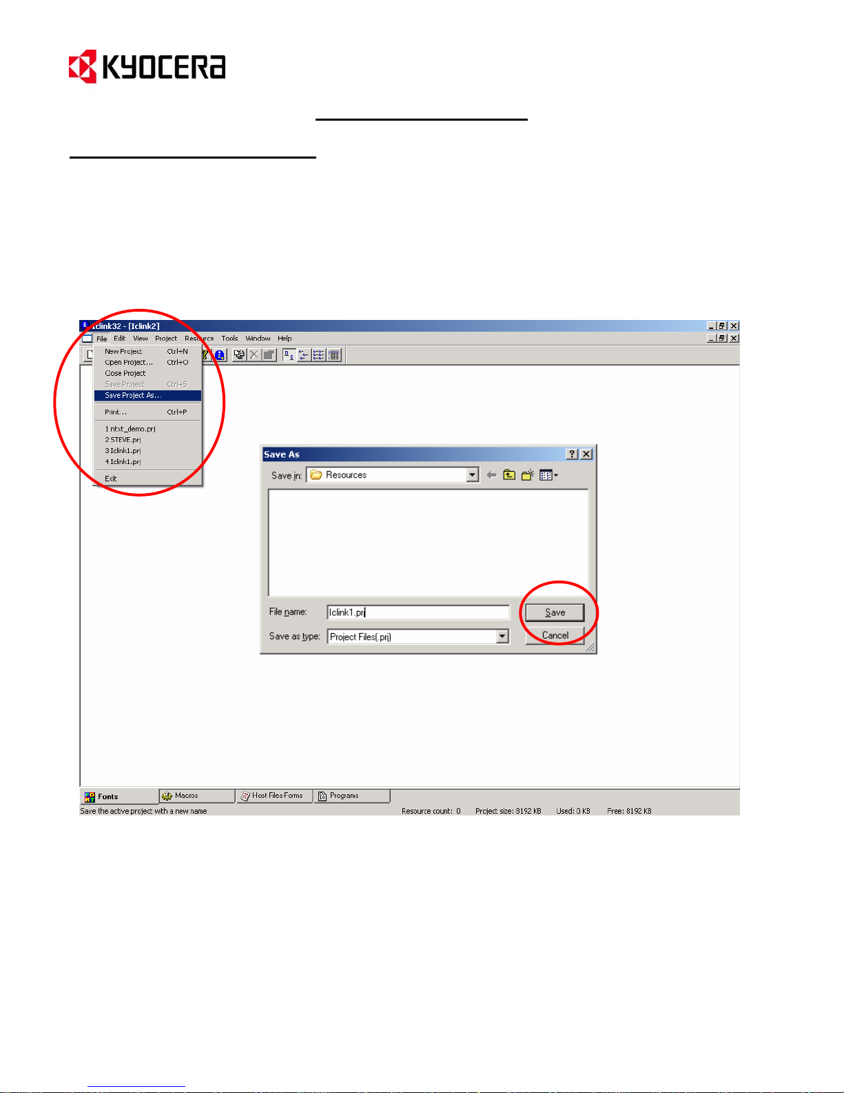
1. From the IC Link menu bar select [File>Save Project As…].
2. This will prompt you for a Folder location, Project File Name in the Save As dialogue box.
3. Once you have defined the IC Link Project File name, click on the Save button to save the IC Link Project
File.
4. The IC Link Project file is now ready to receive its Resources (Fonts, Macros, Host-File Forms, Multi-Part
Forms, EMCR Macros, Bitmap Image Macros, and JPEG Image Macros. Details for each of these
resources are explained in the following pages.
{PAGE }
Page 5
p
A
IC Link for Windows
Setting Preferences
Global Options and File Mappings
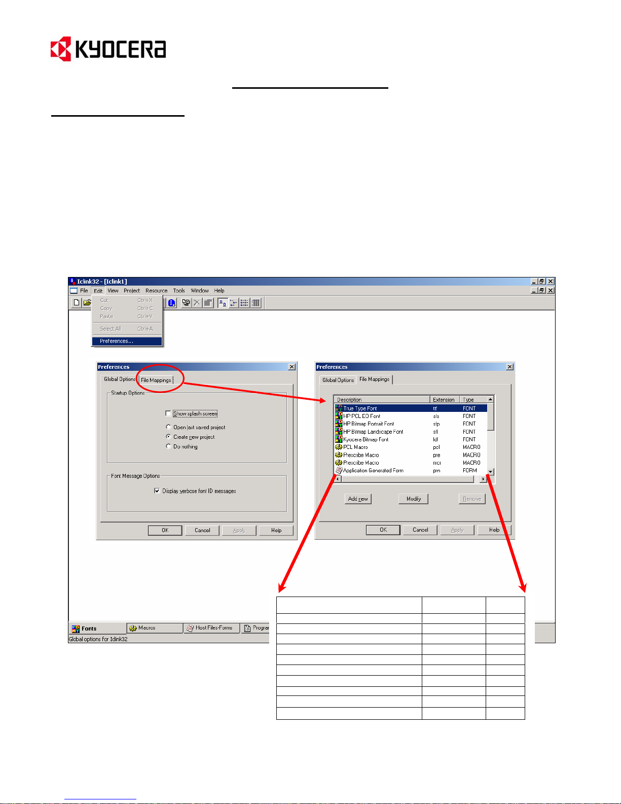
Preferences define IC Link Startup options and the File Mappings (extensions) for the Resource files. These
settings can be accessed as follows:
1. From the menu bar select [Edit>Preferences…]. This will display the Preferences dialogue box.
2. The IC Link Startup Options and Font Messages can be set up under the Global Options tab.
3. The IC Link File Mappings (Resource file extensions) can be defined under the File Mappings tab. The
Default File Mapping table defines how the Resource files are imported into IC Link i.e. – Font, Macro,
Application File, PRESCRIBE Macro, PCL Macro or Application Generated form. Additional File Mappings
can be added and modified as well.
Description Extension Type
TrueType Font ttf Font
HP PCL EO Font sfs Font
HP Bitmap Portrait Font sfp Font
HP Bitmap Landscape Font sfl Font
Kyocera Bitmap Font Idf Font
PCL Macro
PRESCRIBE Macro pre Macro
PRESCRIBE Macro mcr Macro
pplication Generated Form prn Form
Program Data prg Data
Default File Mapping List
cl Macro
{PAGE }
Page 6
IC Link for Windows
Project Menu
Project Settings
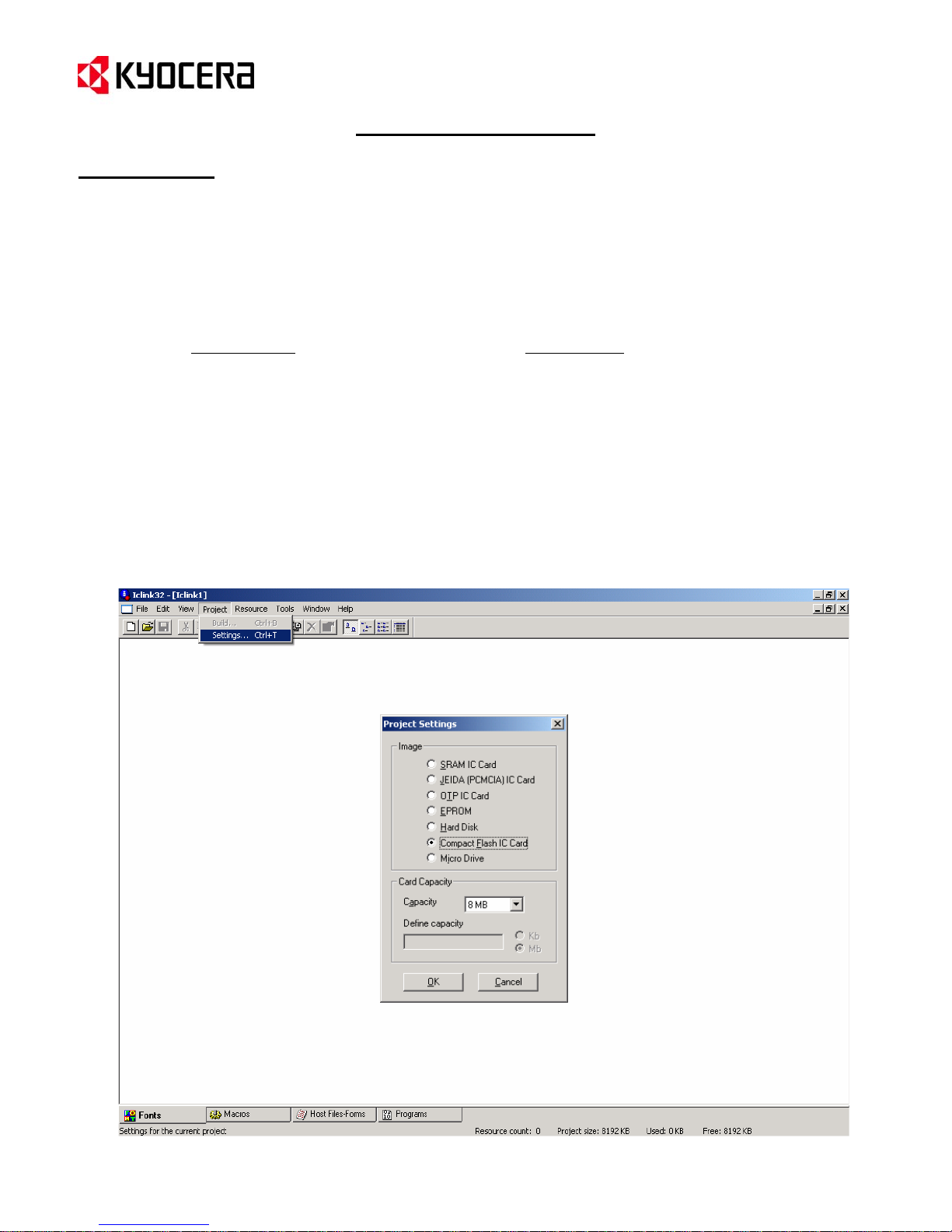
The Project Settings define the IC Card Image type and Capacities. The Project Settings can be accessed as
follows:
1. From the IC Link menu bar select [Project>Settings…]. This will display the Project Settings dialogue box
where the Image and Card Capacity settings are defined as follows:
2. Once you have defined the Project Settings Image and Card Capacity, click on the OK button to submit
Image Settings
• SRAM IC Card
• JEIDA (PCMCIA) IC Card
• OTP IC Card
• EPROM
• Hard Disk
• Compact Flash IC Card
• Micro Drive
the settings with the Project File.
Card Capacity
• 32 KB ~ 128 MB
• Custom Settings
{PAGE }
Page 7
IC Link for Windows
Project Menu
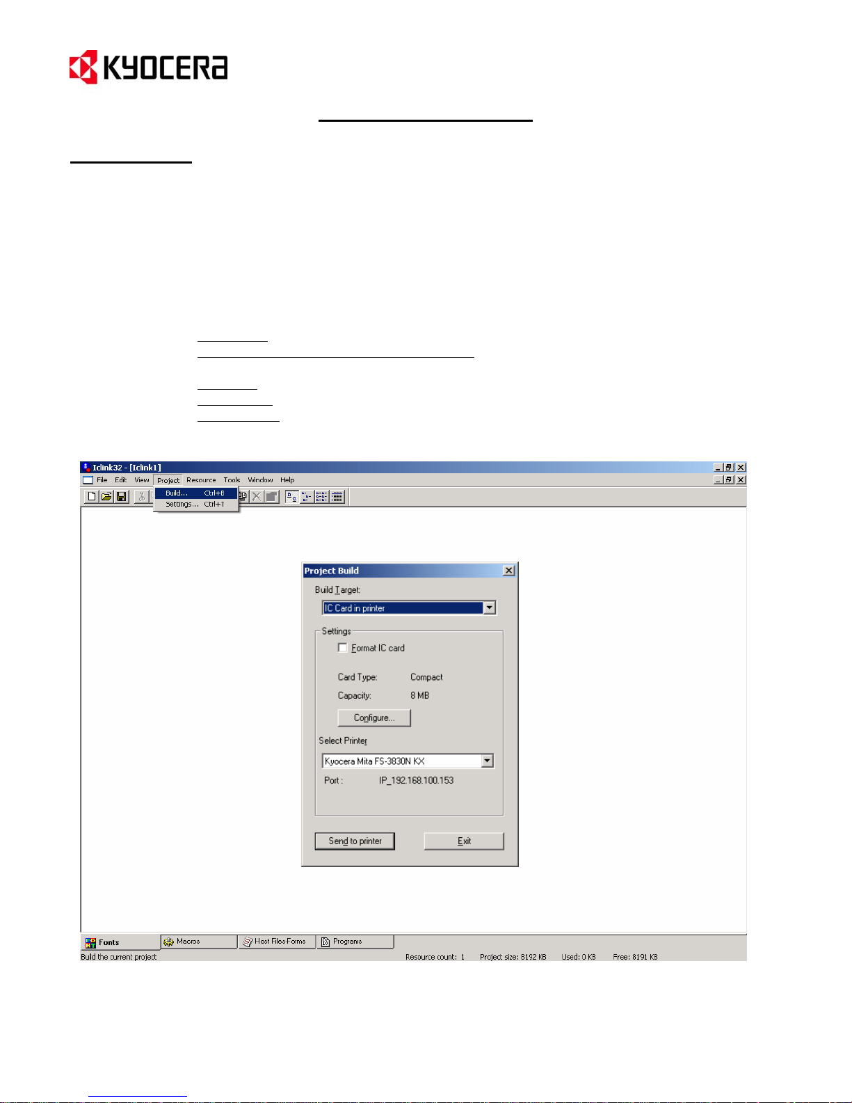
Project Build
Project Build is the action of building the Resource Files (fonts, macros, host-file forms, and program files) onto
the Build Target in the printer which could be an IC Card in printer, Hard Disk / Micro Drive in printer, Export File for
EPROM, or an Export File for JEIDA (PCMCIA) Card. The Project Build settings can be accessed as follows:
1. From the IC Link menu bar select [Project Build…]. This will launch the Project Build settings dialogue
box.
2. In the Project Build box you can define the following:
Build Target – destination for the IC Link Project Files.
Format IC Card or Format hard disk / micro drive – will format (erase) the target image
device (IC card, Hard Drive or Micro Drive).
Configure – will launch the Project Settings dialogue box.
Select Printer – selects the target printer and displays the Port (LPT or IP Address).
Send to printer – executes the Project Build and builds the IC Link Project files onto the
Build Target.
{PAGE }
Page 8
A
IC Link for Windows
Resource Menu
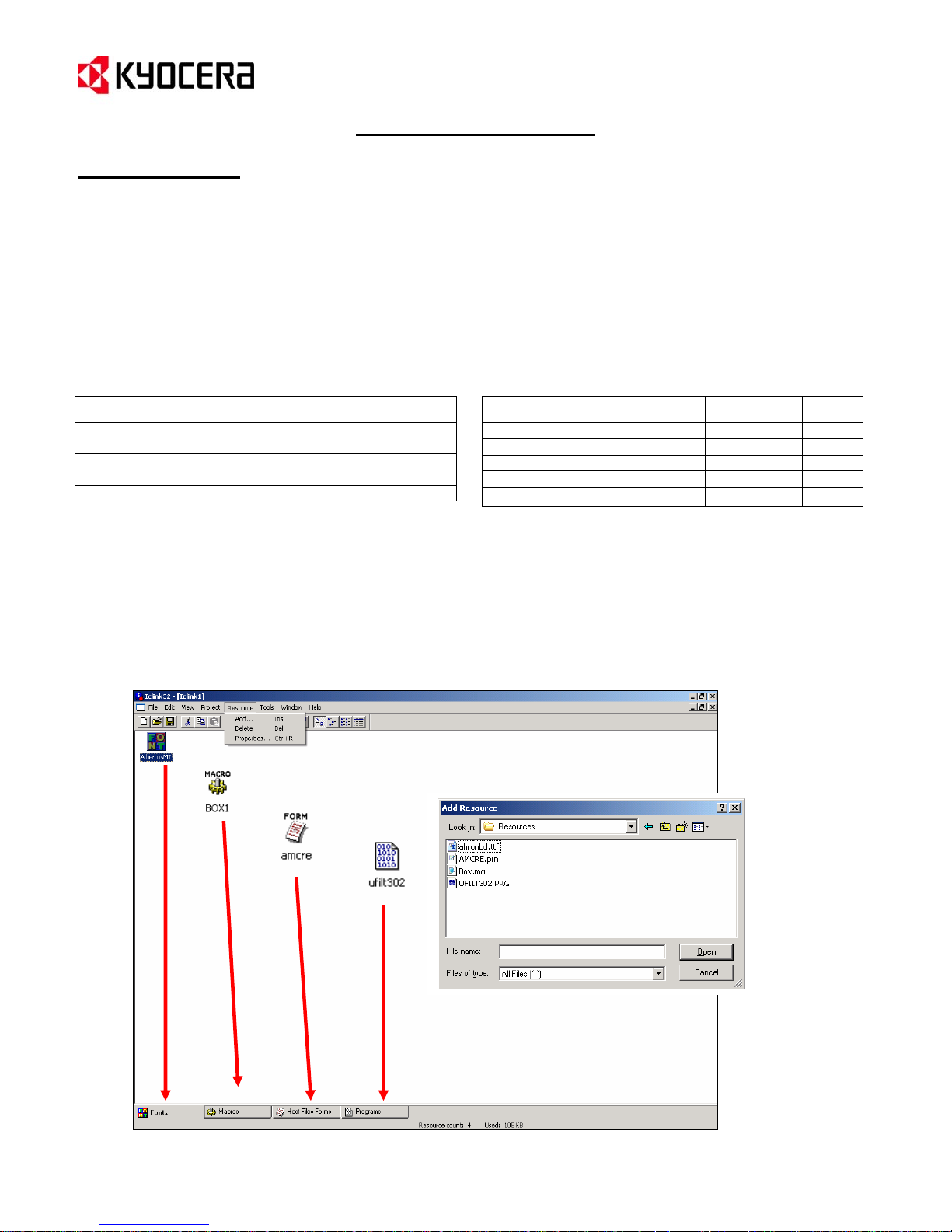
Add & Delete IC Link Project Resource Files
Resource files can be Fonts, Macros, Hosts-Files Forms, and Program files. These files and various combinations
of them can enhance printing environments and provide an added value to the Kyocera print system. Features
such as Electronic Form overlays, Specialized Fonts, Multi-Part Forms, and Application Program Interfaces (API’s)
can be enabled on the Kyocera print system. Resource files can be added or deleted from the IC Link Project file
as follows:
1. From the IC Link menu bar select [Resource>Add…], and from the Add Resource dialogue box browse
to the file you want to add to the IC Link Project. Selection of the Resource file is limited to the following
files types:
Description Extension Type
TrueType Font ttf Font
HP PCL EO Font sfs Font
HP Bitmap Portrait Font sfp Font
HP Bitmap Landscape Font sfl Font
Kyocera Bitmap Font Idf Font
NOTE: IC Link will automatically detect the file extension, and add the Resource file to the appropriate location in
the IC Link Project (Font, Macro, Host-File Form, and/or Program Data). The file type association may be modified
by using the File Mapping feature under the Preferences Settings.
Description Extension Type
PCL Macro pcl Macro
PRESCRIBE Macro pre Macro
PRESCRIBE Macro mcr Macro
pplication Generated Form prn Form
Program Data prg Data
2. To delete a Resource File from your IC Link Project, highlight it in the work area, and select Delete from
the Resource menu or press the Delete key on the keyboard.
3. Properties of each Resource File can be displayed by highlighting the Resource File icon and RightMouse Clicking on it (see next page for more details).
{PAGE }
Page 9
IC Link for Windows
Resource Menu
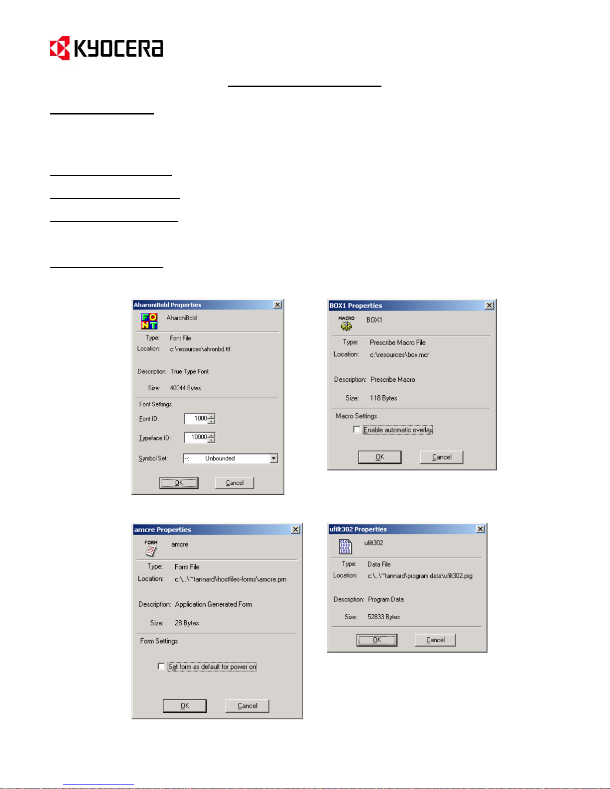
Resource File Properties
Each of the IC Link Project Resource Files has properties associated with them as follows:
Font Resource Properties
ID #, Typeface ID #, and Symbol Set. The Font ID # can be adjusted and is used for PRESCRIBE FONT command.
Macro Resource Properties
include ,macro automatic overlay enable.
Host-File Forms Properties
Set form as default for power on. This setting sets the printer FRPO Interface Dependent Parameter I0 (partition
name) to the name of the Resource file. This is useful for setting partition files to boot at power up for Universal
Filter API’s, AMCR(Automatic) macros and EMCR (Cassette assigned) macros.
Program File Properties
– defines resource type, location, description, and size. Resource settings include Font
– defines resource type, location, description, and size. Resource settings
– defines resource type, location, description, and size. Resource settings include
– defines resource type, location, description and size.
Font Resource Properties
Host-File Forms Properties
Macro Resource Properties
Program File Properties
{PAGE }
Page 10
IC Link for Windows
Tools Menu
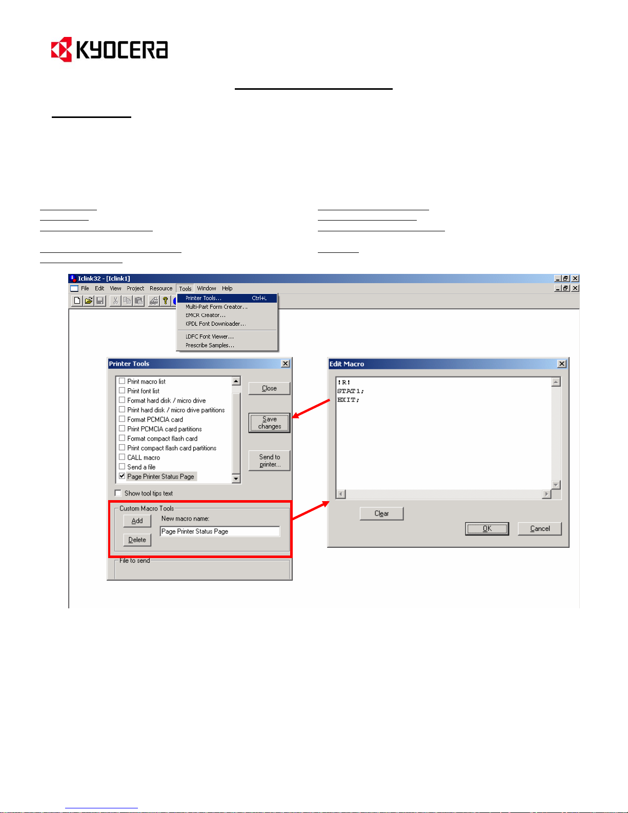
Printer Tools
Printer Tools enables you to test IC-Link Projects and Resource Files by executing some sp ecialized command that
will produce a list or execute a specific command relative to Macro, Font, Host-File Form, and/or Program File
project build. The list of standard Printer Tools include:
1. Print macro list – prints list of RAM and CF card resident macros.
2.
Print font list – prints list of RAM and CF card resident fonts.
Format hard disk / micro drive – formats the printer hard disk or
3.
micro drive.
Print hard disk / micro drive partitions – prints a HDD Partition List.
4.
5.
CMCIA cardFormat P – formats the PCMCIA card in the printer.
*
Custom Printer Tools
In addition to the standard Printer Tools – you can also create your own Custom Printer Tools that can be
customized to fit a specific IC Link Project File.
1. From the [Custom Macro Tools] under the Printer Tools dialogue box, select the [Add] button.
2. Double click on the [New macro name:] field and enter a name for your customized macro tool.
This will add the new tool to the Printer Tool list.
3. Place a “check mark” in the box next to your new tool and double click on it. This will launch the
[Edit Macro] dialogue box.
4. Type the PRESCRIBE command for your customize macro tool into the text area and click on the
[OK] button.
5. On the [Printer Tools] dialogue box, click on the [Save Changes] button to lock in the new
customized macro tool.
Print PCMCIA card partitions – prints a Partition List of the PCMCIA card.
6.
7.
Format compact flash card- formats the compact flash card in the printer.
Print compact flash card partitions – prints a Partition List of the compact
8.
flash card.
Call macro – Prints macro stored on printer.
9.
10. Send a file – sends a file to the printer.
{PAGE }
Page 11
IC Link for Windows
Tools Menu
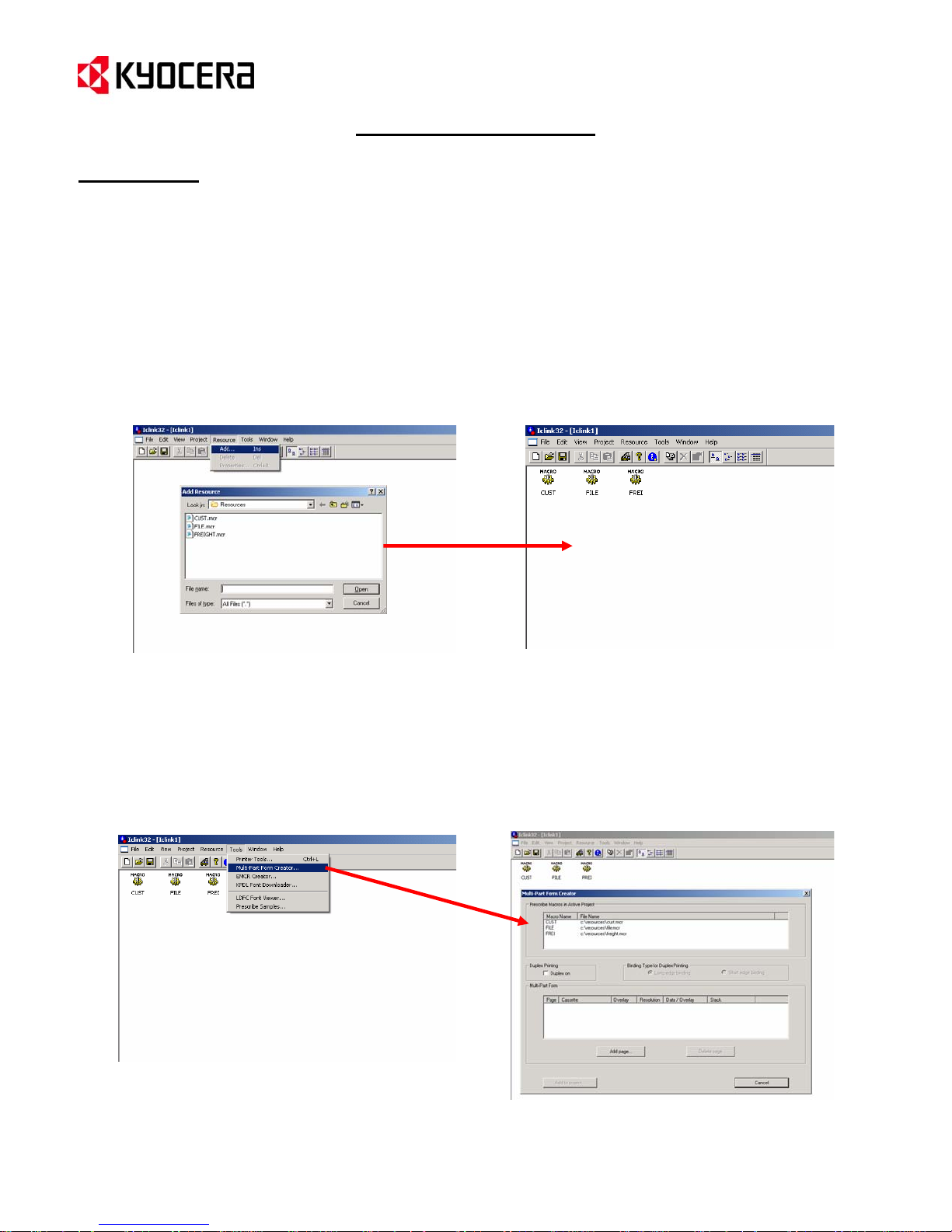
Multi-Part Form Creator
Multi-Part Form Creator will build PRESCRIBE based macro files into a CCPY command. By means of the CCPY
command, the Kyocera-Mita printers can print multiple copies from different cassettes when a print file is sent to the
printer. Each printed page can utilize a different macro and cassette to apply different forms (Customer Copy, File
Copy, Freight Copy).
1. Using the [Resource>Add] feature of IC Link, you can add the PRESCRIBE based macro files into the IC
Link Project File. In this example, the PRESCRIBE macros CUST, FILE, and FREI have been added to the
IC Link Project File.
2. Once the PRESCRIBE macros have been added, you can launch the Mult-Part Form Creator from the
[Tools>Mult-Part Form Creator…] drop down menu. This will launch the launch the Multi-Part Form
Creator dialogue box, which will contain the three PRESCRIBE macro files available for the Mult-Part Form.
{PAGE }
Page 12
IC Link for Windows
Tools Menu
Multi-Part Form Creator (continued)
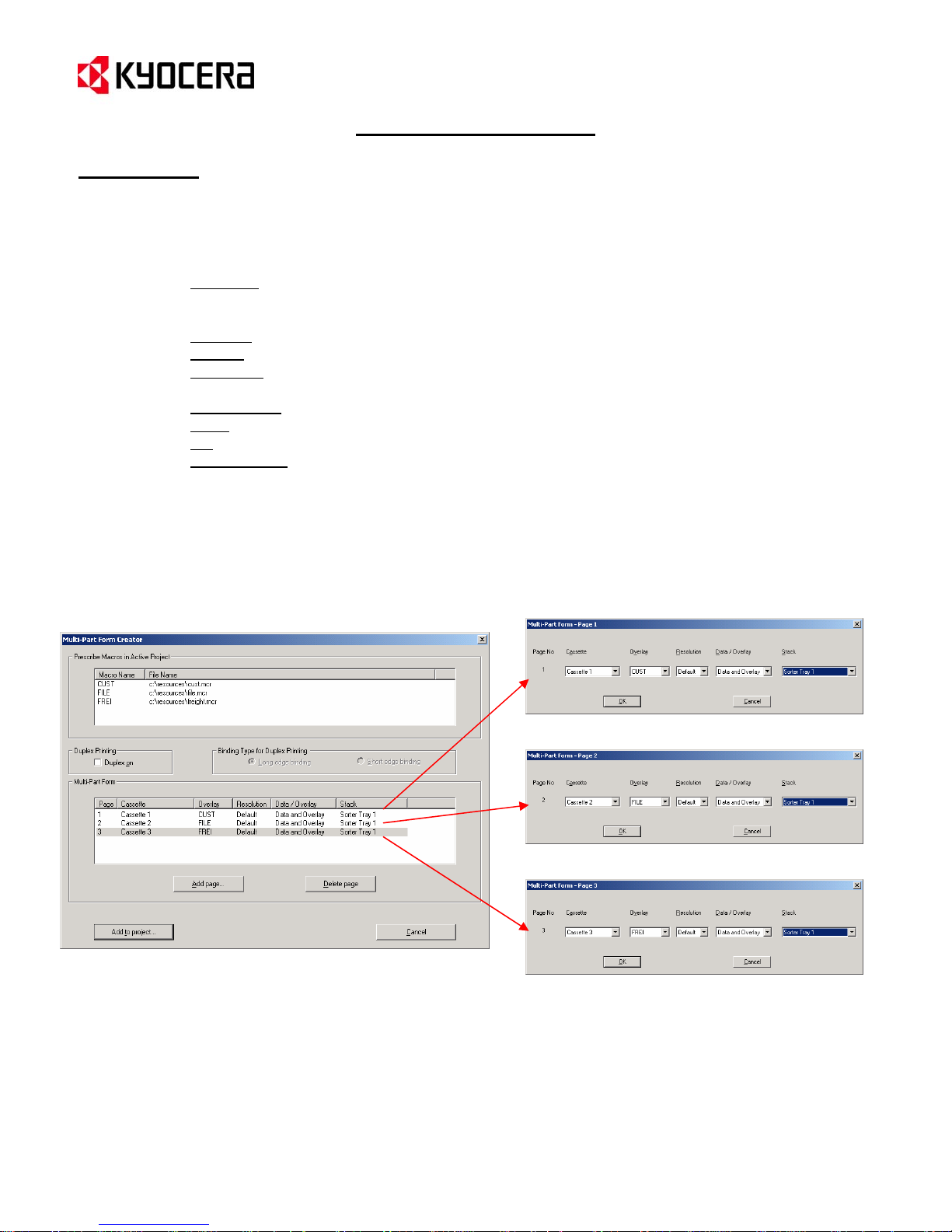
3. With the Multi-Part Form Creator active you can begin to configure your Multi-Part Form with the following
parameters:
a. Add Page – activates a “Multi-Part Form Page”, where the settings can be applied for each of the
pages in the Multi-Part Form. Each time you click on “Add Page” – it allows you to create a
separate page with different Cassette, Overlay, Resolution, Data/Overlay, and Stack settings.
b. Cassette
c. Overlay
d. Resolution
of vector graphics and fonts will not be effected from this setting.
e. Data/Overlay
f. Stack
g. OK – will add the Cassette, Overlay, Resolution, Data/Overlay, and Stack settings to the Page.
h. Add to Project
and Ccpy Disable files (ccpy on.prn and ccpy off.prn).
4. As each Multi-Part Form Page is configured, click on the OK button for each entry. This will create an entry
under the Multi-Part Form field for each page you have configured (i.e. – Multi-Part Form Page 1, MultiPart Form Page 2, and Multi-Part Form Page 3)..
– selects the cassette from which the print page should be taken from.
– assigns the PRESCRIBE macro (Customer, File, or Freight) to the cassette.
– selects the PRESCRIBE and/or Laser-Jet raster graphics resolution. The resolution
– The overlay can be printed out separately or with the print data.
– the stack position of the printer can be defined.
– will build the Multi-Part form into an IC Link Project file and create a Ccpy Enable
Multi-Part Form Page 1
Multi-Part Form Page 2
Multi-Part Form Page 3
{PAGE }
Page 13

IC Link for Windows
Tools Menu
Multi-Part Form Creator (continued)
5. After all the pages have been configured and created in the Multi-Part Form Creator, click on the “Add to
project…” button. This will create two files called ccpy on.prn and ccpy off.prn which can be saved onto
the local PC and added into the IC Link Project File under the “Host-File forms” tab of IC Link.
6. The two files which will be created are the CCPY Enable (ccpy on .prn) and the CCPY Disable (ccpy
off.prn) files. A copy of each of these files can be saved onto the PC as shown in the figures below, and
will also be added to the IC Link Project file under the Host-File forms tab as *.prn files.
{PAGE }
Page 14

IC Link for Windows
Tools Menu
Multi-Part Form Creator (continued)
7. The ccpy on.prn and ccpy off.prn files are now located in the “Host-Files Forms” in the IC Link Project
File now and ready to be built onto the target storage device of the printer (HDD, Microdrive, or Compact
Flash Card). These files are the “ON” and “OFF” triggers for the Multi-Part Form feature.
8. The Multi-Part Form can be turned ON and OFF in the following manner.
a. Right Mouse Click on the ccpy on file, this will launch the ccpy on file properties.
b. Under the ccpy on Properties, select the check box for “Set form as default for power on” and
then click on the OK button. This will make the ccpy on.prn execute at printer power ON and start
the Multi-Part form feature.
{PAGE }
Page 15

IC Link for Windows
Tools Menu
Multi-Part Form Creator (continued)
9. After setting the ccpy on.prn properties, select [Project>Build] from the drop down menu. This will launch
the “Project Build” dialogue box where you can check/configure the Project Settings as follows:
a. Build Target
Disk/Micro Drive in printer, Export File for EPROM, or Export File for JEIDA (PCMCIA) Card.
b. Format IC card
c. Configure
d. Select Printer
e. Send to Printer
10. After all the Project Build settings have been completed, click on the [Send to printer] button, a WARNING
message will display warning the Format of the Compact Flash Card will erase all data on that Compact
Flash Card.
11. Click on the [OK] button, and a message will display “Project was written to the print spooler”.
12. The printer LCD will flash “Processing” and then return to the “Ready” state. Turn the printer power “OFF”
and then “ON” to start the Multi-Part Form Macro.
13. Send your print data to the printer. The Multi-Part Form will be active for any print jobs sent to the printer.
NOTE: Using Logical Printer Ports, it is possible to accommodate multiple Multi-Part Forms projects on one printer
or to dedicate to one specific Printer Port using a PRESCRIBE RWER command to trigger the ccpy on.prn at the
Start of Job String.
– defines the target storage device for the project file (IC Card in printer, Hard
– will format the PCMCIA or CF card before building the project file to the card.
– defines the IC Card type and size.
– sets the target printer.
– sends the project file to the printer.
{PAGE }
Page 16

IC Link for Windows
Tools Menu
EMCR Creator
By means of the PRESCRIBE EMCR command, the Kyocera Mita printers can have PRESCRIBE based macros
assigned to a cassette, so that when print jobs are pulled from that cassette the macro will overlay with the print
data. Each cassette can use a macro to apply a different form. Using EMCR is similar in concept to having preprinted materials in the cassettes, less the expense of the pre-printed materials. The number of EMCR macros is
limited to the number of cassettes.
1. Using the [Resource>Add] feature of IC Link, you can add the PRESCRIBE based macro files into the IC
Link Project File. In this example, the PRESCRIBE macros CUST, FILE, and FREI have been added to the
IC Link Project File.
2. Once the PRESCRIBE macros have been added, you can launch the EMCR Creator from the
[Tools>EMCR Creator…] drop down menu. This will launch the launch the EMCR Creator dialogue box,
which will contain the three PRESCRIBE macro files available for the EMCR.
{PAGE }
Page 17

IC Link for Windows
Tools Menu
EMCR Creator (continued)
3. With the EMCR Creator active you can begin to configure your EMCR Macro by selecting the Paper
Source, clicking on the “Assing Macro / modify…” button and defining the following parameters in the
“Macro to Paper Source” dialogue box :
a. Macro
b. Parameters
c. Repeat Count
4. As each “Macro to Paper Source” is configured, click on the [OK] button to register each setting. This will
create an entry under the Macro – Paper Source Assigner field for each Cassette you have configured
(i.e. – Cassette 1, Cassette 2, Cassette 3 etc.).
– Drop down menu lists the available macros to assign to the Paper Source.
– Open text field which allows additional PRESCRIBE Commands associated with the
Macro file such as resolution settings or macro positioning.
– Allows repeat count for the Macro to be assigned.
{PAGE }
Page 18

IC Link for Windows
Tools Menu
EMCR Creator (continued)
5. After all the pages have been defined in the EMCR Creator, click on the [Add to project…] button. This
will create two files called ccpy on.prn and ccpy off.prn which can be saved onto the local PC and added
into the IC Link Project File under the “Host-File forms” tab of IC Link.
6. The two files which will be created are the EMCR Enable (emcr on.prn) and the EMCR Disable (emcr
off.prn). One copy of each of these files can be saved onto the PC as shown in the figures below, and will
also be added to the IC Link Project file under the Host-File forms tab as *.prn files.
{PAGE }
Page 19

IC Link for Windows
Tools Menu
EMCR Creator (continued)
7. The emcr on.prn and emcr off.prn files are now located in the “Host-Files Forms” of the IC Link Project
File and are ready to be built onto the target storage device of the printer (HDD, Microdrive, or Compact
Flash Card). These files are the “ON” and “OFF” triggers for the EMCR Macro feature.
8. The EMCR Macro auto start can be set up in the following manner.
a. Right Mouse Click on the emcr on.prn file, this will launch the emcr on.prn file properties.
b. Under the emcr properties, select the check box for “Set form as default for power on” and then
click on the OK button. This will enable the EMCR Macro to start up at machine power up and
keep it running all the time.
{PAGE }
Page 20

IC Link for Windows
Tools Menu
EMCR Creator (continued)
9. After setting the emcr on.prn properties, select [Project>Build] from the drop down menu. This will launch
the “Project Build” dialogue box where you will need to configure the Project Build settings as follows:
a. Build Target
Disk/Micro Drive in printer, Export File for EPROM, or Export File for JEIDA (PCMCIA) Card.
b. Format IC card
c. Configure
d. Select Printer
e. Send to Printer
10. After all the Project Build settings have been completed, click on the [Send to printer] button, a WARNING
message will display warning the Format of the Compact Flash Card will erase all data on that Compact
Flash Card.
11. Click on the [OK] button, and a message will display “Project was written to the print spooler.”.
12. The printer LCD will flash “Processing” and then return to the “Ready” state. Turn the printer power “OFF”
and then “ON” to start the EMCR Macro.
13. Send your print data to the printer. Because the EMCR Macro is dependent on its assigned cassette, the
EMCR Macro will not be initiated until a print job is sent to the respective cassette.
– defines the target storage device for the project file (IC Card in printer, Hard
– will format the PCMCIA or CF card before building the project file to the card.
– defines the IC Card type and size.
– sets the target printer.
– sends the project file to the printer.
{PAGE }
Page 21

IC Link for Windows
Tools Menu
KPDL Font Downloader
KPDL Font Downloader is a PostScript font tool that has been built into IC Link. It gives you the ability to download
PostScript (*.pfb) fonts to the Kyocera printer (the printer must support KPDL). Like the Bitmap fonts mentioned
under the “Resource Menu” on page 6, the PostScript fonts can also be saved to a Compact Flash Card and the
Printer HDD or Micro Drive.
1. Launch the KPDL Font Downloader tool by selection [Tools>KPDL Font Downloader …]. This will display
the KPDL Font Downloader dialogue box, where you can select the PostScript font and where on the
printer to store the fonts.
{PAGE }
Page 22

IC Link for Windows
Tools Menu
KPDL Font Downloader (continued)
2. With the KPDL Font Downloader active, select the Add button, and select the PostScript fonts (*.pfb) files
you wish to load onto the printer.
3. Select the PostScript fonts you wish to download to the printer and click on the OK button. This will add
the fonts to the KPDL Font Downloader, and populate the font information field with the Font Name, Target
Font File, Local File Path and the Font File Size.
{PAGE }
Page 23

IC Link for Windows
Tools Menu
KPDL Font Downloader (continued)
4. With the fonts loaded into the Font Downloader, make the following selections:
a. Medium in Printer – Target storage for the fonts, Compact Flash or Printer Hard Disk / Micro Drive
b. Select Printer
available print devices relative to the Windows Print Drivers loaded on the PC.
c. Send to Printer
d. Print font list
have been written to the printer (see list on next page). Does not print Bitmap font list.
5. Once the “Send to printer” button has been selected, the selected fonts will be downloaded to the the
printer and stored on the selected Medium (Compact Flash Card or Hard Disk / Micro Drive).
6. To confirm that all the selected fonts have been properly loaded to the printer, click on the Print font list. A
User Defined Scalable Font List will print out at the printer. The list should contain all the fonts loaded with
the KPDL Font Downloader (See the next page for an example of the Font List).
– From the drop down menu, select the target printer. This selection will list all the
– Will send the fonts to the target printer and storage medium.
– Will generate a KPDL (PostScript) font list. This can be used to confirm that the fonts
{PAGE }
Page 24

IC Link for Windows
Tools Menu
KPDL Font Downloader (continued)
Sample of User Defined Scaleable Font List
{PAGE }
Page 25

IC Link for Windows
Tools Menu
LDFC Font Viewer
LDFC Font Viewer is a tool built into IC Link for viewing the Kyocera created LDFC Bitmap fonts. Historically these
types of fonts would have been created using a legacy Kyocera Utility called Font Logo Master. This tool would be
more commonly used for legacy Kyocera Bitmap Fonts. Another method for viewing the Bitmap font is to print a
Font Status Page, and is described in the following pages under Font Status Page.
1. Select the [Tools>LDFC Font Viewer ...] from the menu bar. This will launch the LDFC Font Viewer.
{PAGE }
Page 26

IC Link for Windows
Tools Menu
LDFC Font Viewer (continued)
2. With the LDFC Font Viewer running, select [File>Open], and browse to your folder location which has the
Kyocera Bitmap Fonts. Select the Font file (*.LDF) and click on the Open button.
{PAGE }
Page 27

IC Link for Windows
Tools Menu
LDFC Font Viewer (continued)
3. This will load the selected Kyocera Bitmap font (*.LDF) into the Font Viewer. The Font Viewer will display a
Character Map of the font. This information can be useful in isolating a font and/or printer symbol set issue
with an LDF font.
NOTE: The LDFC Font Viewer will only display the Font Status Page for a Kyocera Bitmap font with the LDF font
extension. To create a Font Status Page for standard Bitmap fonts please see the following pages under the Font
Status Page title.
{PAGE }
Page 28

IC Link for Windows
Font Status Page
A Bitmap Font Status Page can be printed from the printer, by issuing the following PRESCRIBE command to the
printer:
This command will instruct the print controller to print a Font Status Page of the active bitmap font, and will
represent the font characteristics with a table of mapped bits for each character used in the font. This type of font
information is critical for advanced troubleshooting efforts with fonts and/or printer symbol set issues.
!R! FSTS; EXIT;
{PAGE }
Page 29

IC Link for Windows
Tools Menu
PRESCRIBE SAMPLES
PRESCRIBE Samples is a tool for viewing PRESCRIBE commands, the command format and parameters. Each
of the PRESCRIBE commands has a working template which can be sent to any of the Kyocera printers to
demonstrate the command’s function. With the PRESCRIBE Samples module running you can view all the
PRESCRIBE Commands which are arranged into separate folders by category.
1. To access the PRESCRIBE Samples, select [Tools>Prescribe Samples…] from the menu bar in IC Link.
This will launch the PRESCRIBE Samples module of IC Link.
{PAGE }
Page 30

IC Link for Windows
Tools Menu
PRESCRIBE SAMPLES (continued)
2. Select the [Page Control, Text] folder under the Prescribe Commands field to open up the folder and
display the selection of Prescribe commands relative to Page Control.
3. Select the [TEXT] command, and note the Prescribe Sample for TEXT Command, Command Format /
Short Description, and Parameters of TEXT Command fields. You now have a visual of the
PRESCRIBE Command, Sample of the command, command syntax format, and command parameter
values.
Additional features of the PRESCRIBE Sample module include:
NOTE: The PRESCRIBE Sample for Text Command can be copied and pasted into Text Pad or Notepad to use as
a template to customize the command syntax to meet your requirement.
TEXT
• Prescribe Command Search
• Select Printer / Send to printer
PRESCRIBE Sample to the printer.
– will search for a particular PRESCRIBE command.
– allows the user to define the target printer and to send the
{PAGE }
Page 31

IC Link for Windows
IC Link Image Converter
IC Link also comes equipped with an image converter which will encompass rasterized data from a *.BMP or
*.JPEG file with PRESCRIBE Macro commands. Keeping in mind the quality of the scanned image, this feature of
IC Link can be used as a method to create simple PRESCRIBE based forms from scanned images. Generally the
*.BMP converted image is used for Kyocera monochrome printers and the *.JPEG converted image can be used for
Kyocera color printers.
Converting *.BMP or *.JPEG Image for PRESCRIBE Macro
1. From the IC Link menu bar, select [Resource>Add]. An Add Resource dialogue box will
appear, and you can browse to the location of the *.bmp or *.jpeg file and select it and
click on the Open button. This will launch the Convert Bitmap to Prescribe macro or
Convert JPEG to Prescribe macro dialogue box (depending on the type of image you have
selected).
{PAGE }
Page 32

IC Link Image Converter
Converting *.BMP or *.JPEG Image for PRESCRIBE Macro
2. With the Bitmap Conversion dialogue box open, you make settings which will define the characteristics
of the PRESCRIBE macro as follows:
Macro Name – Select name
of macro. Macro name is
limited to 4 characters.
Unit – Unit of measurement
for the *.bmp file
(Centimeters,
Inches, Dots).
Position X / Position Y –
Defines the position of the
macro file with
X (left to right) and Y (top to
bottom) coordinates on the
page. If this position is not
defined here – then it must be
defined in the actual macro
file.
Width/Height - Identifies the
width and height of the
scanned image on print out.
3. Once you have defined all the macro settings and saved the macro onto to the PC by clicking on the
4. After the macro file has been added to the IC Link Project File, then you can build it to the Printer
respect to the
[Save macro…] button,, you can add it to the IC Link Project File by clicking on the [Add to Project]
button. This will create a Macro Icon under the [Macro] tab of the IC Link Project File.
following the instructions for under the Project Menu – Project Build and Project Settings on page 6
of this document.
IC Link for Windows
*.BMP Conversion
Create Color Raster Data
for Color Printer –Defines
the data as “rasterized for
color. This will only support
bitmap images scanned as
color data.
Raster Resolution – Defines
the Width and Height of the
bitmap file
Defined in DPI as follows
(100, 150, 200,300, or 600).
The default of the scanner is
300 DPI.
Orientation – Defines page
orientation. If left blank, the
page orientation will follow
what is set on the printer.
Save macro – saves the
macro file onto the PC for
future use.
being converted.
{PAGE }
Page 33

H
IC Link Image Converter
Converting *.BMP or *.JPEG Image for PRESCRIBE Macro (continued)
1. With the JPEG Conversion dialogue box open, you make settings which will define the charac teristics
of the PRESCRIBE macro as follows:
Macro Name – Defines the
Macro name. Requires f
letters to define the name
Unit – Defines the Unit of
measurement for the Macro.
Accept default settings.
Position - Defines the
position of the macro file
with
respect the X (left to
right) and Y (top to
bottom) coordinates on the
page. If this position is not
defined here – then it must
be defined in the actual
macro file.
2. Once you have defined all the macro settings and saved the macro onto to the PC by clicking on the
our
.
[Save macro…] button, you can add it to the IC Link Project File by clicking on the [Add to Project]
button. This will create a Macro Icon under the [Macro] tab of the IC Link Project File.
IC Link for Windows
*.JPEG Conversion
Raster Resolution – Defines the
Width and Height of the bitmap
being converted. Defined in
file
DPI as follows (100, 150,
200,300, or 600). The default of
the scanner is 300 DPI.
Orientation – Defines page
orientation. If left blank, the
page orientation will follow what
is set on the printer.
Output Width and Output Height
- Defines the Image Width and
Height. It is not necessary to define
any values here, as the Width and
Height can be defined in the Macro
Call with two parameters in the
Call statement.
!R! CALL <macroname>W,H;EXIT;
W = Image Width
= Image Height
{PAGE }
Page 34

IC Link Image Converter
Converting *.BMP or *.JPEG Image for PRESCRIBE Macro (continued)
3. After the Bitmap Converted macro file has been added to the IC Link Project File, you can build it to the
Printer by selecting [Project>Build]. This will launch the Project Build dialogue box and you can
Configure the IC Memory Card Settings and Select the target printer to build the IC Link Project File.
Additional details on Project Builds can be referenced on page 6 of this User Guide.
IC Link for Windows
{PAGE }
Page 35

IC Link for Windows
KX Print Driver Prologue / Epilogue Feature
Initiating PRESCRIBE Macros from Microsoft Windows
The Kyocera Extended Print Driver, KX Print Driver, has an added module called Prologue / Epilogue. This module
allows the user to start (Prologue) and to end (Epilogue) a Windows print job with a text based file (Notepad or
Wordpad) containing PRESCRIBE commands. This feature is generally used to initiate a CALL for a Macro or an
AMCR for a Macro. These Macro’s are described as follows:
CALL Macro
AMCR Macro
In each case a PRESCRIBE Macro is required to be built onto the printer. The following instructions outline the
process of creating the trigger to initiate or call these macros using the Kyocera KX Print Driver Prologue / Epilogue
feature as follows:
CALL Macro / AMCR Macro
1. Determine which type of Macro you are setting up on the printer. CALL, AMCR, EMCR. Using Microsoft Notepad
and the sample templates given below, create the Microsoft Notepad as follows:
NOTE: In both cases for the CALL Macro and the AMCR Macro, the <macroname> is substituted with the actual
macro name.
2. Save the Notepad file to a folder on the PC, the file will need to exist in a permanent location on the PC so it is
important to select a folder that does not have a chance of being deleted or moved at a later time.
– will call a macro to overlay with print data on the first page.
– will call a macro to overlay with print data on all pages printed to the printer.
CALL Macro
AMCR Macro
{PAGE }
Page 36

IC Link for Windows
KX Print Driver Prologue / Epilogue Feature
Initiating PRESCRIBE Macros from Microsoft Windows (continued)
3. Go to the Printers Folder on you PC and open the properties of the KX Print Driver you are using for the target
printer.
4. Select the Device Settings tab.
5. Click on the PDL button to display the PDL settings of the print driver.
6. Using the drop down menu under the Printer Description Language, select PCL 5e and click OK.
7. Click OK again to close the print driver properties and set the PDL change.
NOTE: The print driver PDL will change to PCL 5e and be displayed in the lower left hand corner of the
illustration of the printer.
{PAGE }
Page 37

IC Link for Windows
KX Print Driver Prologue / Epilogue Feature
Initiating PRESCRIBE Macros from Microsoft Windows (continued)
7. Open the Print Driver properties again and click on the General tab.
8. Click on the Printing Preferences button. This will display the print driver printing preferences.
9. With the Printing Preferences displayed, Select the Prologue / Epilogue tab and un-check the Prologue /
Epilogue Disable Feature by clicking on the check box.
{PAGE }
Page 38

IC Link for Windows
KX Print Driver Prologue / Epilogue Feature
Initiating PRESCRIBE Macros from Microsoft Windows (continued)
10. With the Prologue / Epilogue feature enabled, select the Add button.
11. Browse to the Notepad file with the PRESCRIBE Call statement for the desired macro, select it and click on the
Open button.
12. The Notepad file with the PRESCRIBE Call statement will be added to the Prologue/Epilogue Data Files: field
of the driver.
{PAGE }
Page 39

IC Link for Windows
KX Print Driver Prologue / Epilogue Feature
Initiating PRESCRIBE Macros from Microsoft Windows (continued)
13. Select Start of the Page (active for PCL 5e/5c), and enter the page number or ranges of pages you wish to insert
the PRESCRIBE Call statement at. In this case, you will enter in a 1, and click the OK button to submit the
settings.
The Prologue/Epilogue feature of the KX Print Dri ve r has now been configured with the PRESCRIBE Call statement to
initiate a PRESCRIBE Macro at the start of page 1. Each time you print from this print driver, the PRESCRIBE Macro
will execute and overlay a form or execute the macro.
As there are other considerations for printing environments, there are also other methods for calling or initiating a
PRESCRIBE based macro. To learn more about these methods, please contact your Authorized Kyocera Mita Dealer.
{PAGE }
 Loading...