

KYMCO Vitality 50, 4 STROKE, 2 STROKE Owner's Manual

KWANG YANG MOTOR CO., LTD.
OWNER’S MANUAL Vitality 50
2 STROKE & 4 STROKE


Dear KYMCO Scooter Users:
Thank you for purchasing this KYMCO scooter and welcome to the
family of KYMCO scooter riders. To enjoy safer and more pleasant
riding, become thoroughly familiar with this owner's manual before you
ride the scooter. Your safety depends not only on your own alertness
and familiarity with the scooter but also the scooter’s mechanical
condition. A pre-ride inspection before every outing and regular
maintenance are essential. The quality of each KYMCO scooter is
guaranteed.
NOTE: 1. The information and specifications stated in this manual are for
reference only and subject to change without notice.
2. When starting the engine, the battery must be installed to
facilitate starting and increase the engine performance.

TABLE OF CONTENTS
1. ENSURING A SAFE RIDE 1
2. PARTS LOCATION 3
VIN NUMBER 7
ENGINE NUMBER 8
KEY NUMBER 9
3. OPERATING INSTRUCTIONS 10
IGNITION SWITCH 10
HANDLEBAR LOCK 10
ELECTRIC STARTER BUTTON 11
HEADLIGHT SWITCH 11
HEADLIGHT DIMMER SWITCH 12
PASSING SIGNAL SWITCH 12
HORN BUTTON 13
TURN SIGNAL SWITCH 13
SEAT LOCK 14
MET-IN BOX (UNDERSEAT STORAGE) 14
HELMET HOLDER 14
CENTRE HOOK 15
INSTRUMENTS & INDICATORS 16
4. PRE-RIDE INSPECTION 18
ADVANCE INSPECTION 18
ENGINE OIL LEVEL / REFILLING 18
TIRE INSPECTION 21

TABLE OF CONTENTS TABLE OF CONTENTS
FUEL LEVEL INSPECTION / REFILLING 23
STEERING HANDLEBAR 24
INSTRUMENT LIGHTS INSPECTION 24
BRAKE FLUID LEVEL INSPECTION 25
BRAKE PAD WEAR 26
BRAKE SHOE WEAR 26
BRAKE LEVER FREE PLAY INSPECTION & ADJUSTMENT 27
HORN / LIGHT INSPECTION 29
FRONT / REAR SHOCK ABSORBER INSPECTION 30
BRAKE PERFORMANCE INSPECTION 30
BACK MIRROR ANGLE CHECK 30
LICENSE PLATE CHECK 30
REFLECTOR CHECK 30
PREVIOUS ABNORMAL PARTS INSPECTION 30
LUBRICATION POINT CHECK 30
5. ENGINE STARTING METHODS 31
6. NORMAL RIDING METHOD 34
7. PRECAUTIONS FOR RIDING 36
8. HOW TO STOP RIDING 39
9. EASY MAINTENANCE 41
AIR FILTER CLEANING & REPLACEMENT 41
CLEANING EXTERIOR SURFACES 45
BATTERY 46

TABLE OF CONTENTS TABLE OF CONTENTS
FUSE REPLACEMENT 48
ENGINE OIL CHANGE (4 STROKE) 50
TRANSMISSION GEAR OIL 51
SPARK PLUG INSPECTION 55
BRAKE FLUID LEVEL INSPECTION / REFILLING 56
RUBBER COVER INSPECTION FOR WIRE & CABLE 56
10. IMPORTANT NOTICES 57
POLLUTION-FREE MAINTENANCE SCHEDULE 58
SPECIFICATIONS
59
11. KYMCO CLEAN AIR SYSTEM (FOR EURO 2) 61
1. ENSURING A SAFE RIDE
RIDING GEAR
• In order to ensure a safe ride be sure to relax and wear
comfortable clothing.
• Observe all traffic laws and be careful.
o Always wear a helmet and make sure it is fastened.
o Arrange your clothing – fasten shirt cuffs to prevent
them from hooking the brake lever.
o Wear low healed shoes.
o When riding, use both hands to grasp the handlebar.
It is very dangerous to hold the handlebar with just
one hand.
- 1 -
• A scooter rider should NEVER wear loose clothing
• To avoid the risk of being burned, DO NOT touch the
exhaust muffler during or up to 10 minutes after riding.
• When parking the scooter, keep it away from dry grass
or any other flammable objects or materials.
RIDING METHOD
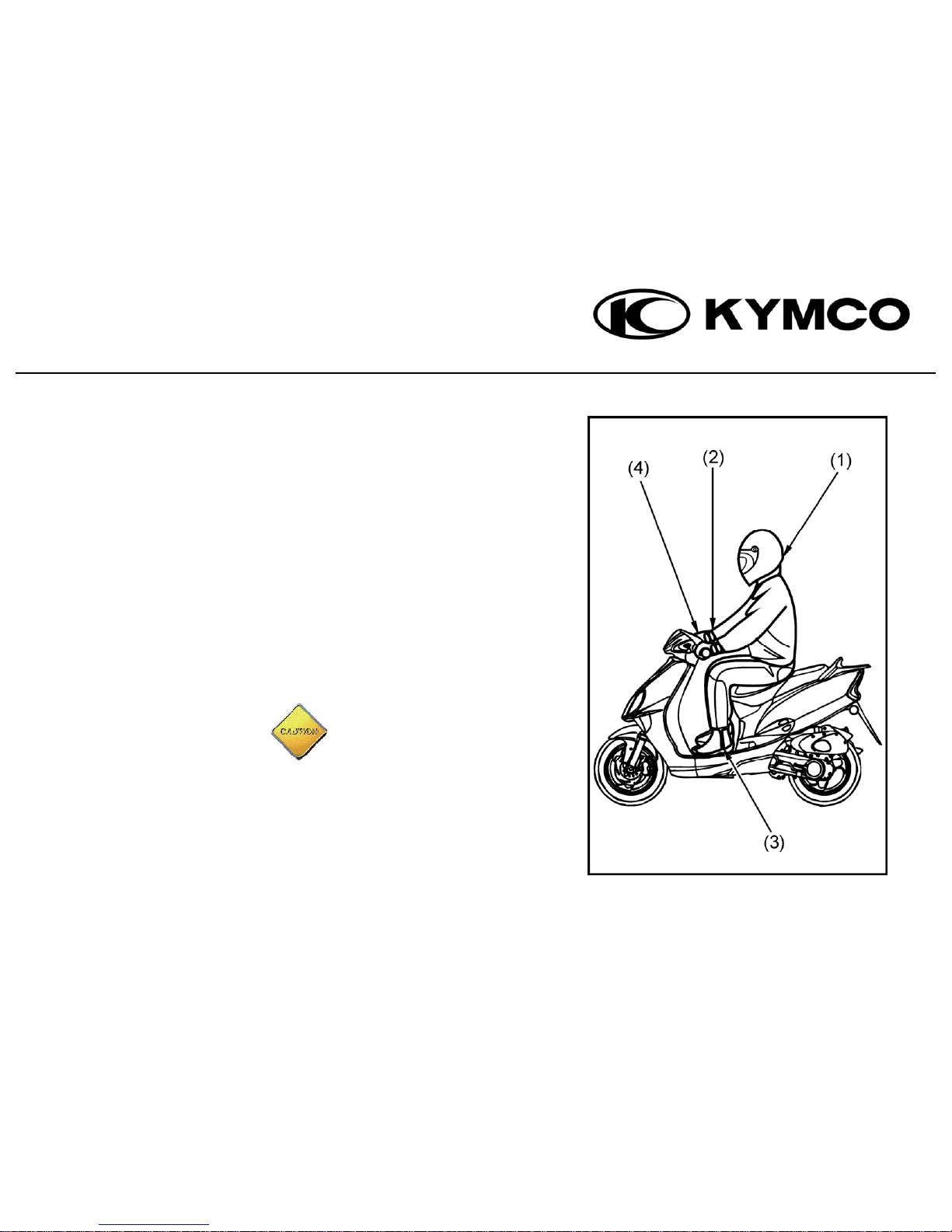
• Safety on a two-wheeled vehicle is influence by seating
position. The rider should sit on the central part of the
seat cushion. Should the rider sit on the rear part of the seat,
the load of the front wheel will decrease, the handlebars
could swing therefore putting the rider in danger.
• When making a turn, it will be easier for the rider to steer
the scooter by leaning the body inward slightly. Failure
to do this could result in a loss of balance.
• When riding on a damaged or gravel road be sure to slow
down your speed and hold the handlebars tightly.
- 2 -
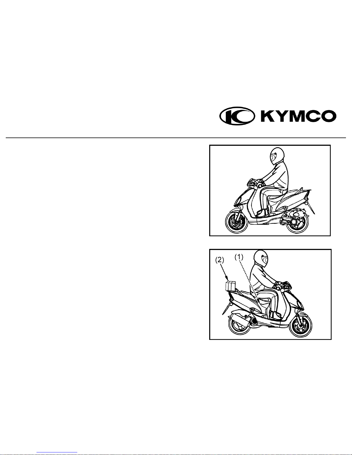
CARRYING GOODS
• Maintain proper posture at all times while operating the scooter.
• The handlebars will feel different when carrying goods on
the scooter. Overloading may cause the handlebars to swing.
Do not exceed maximum loading capacity.
i. Maximum loading capacity of the met-in box is 10 kg.
ii. Maximum loading capacity of the rear carrier is 5 kg.
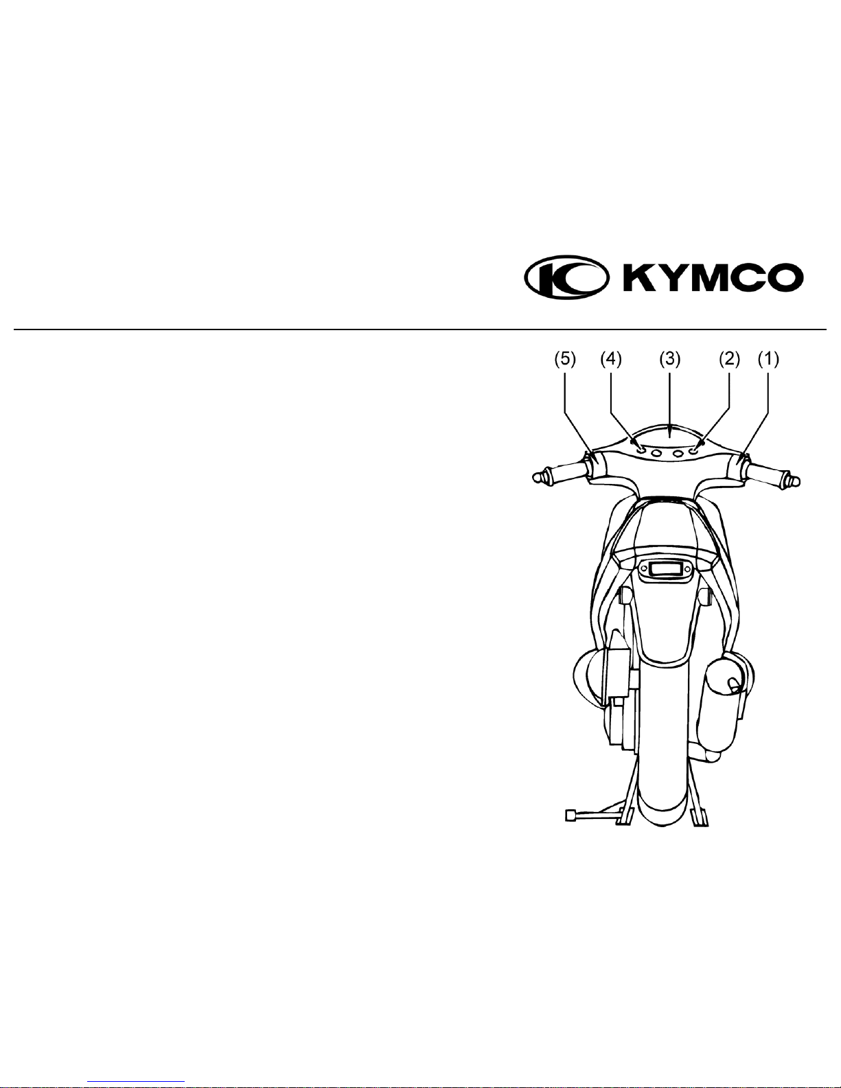
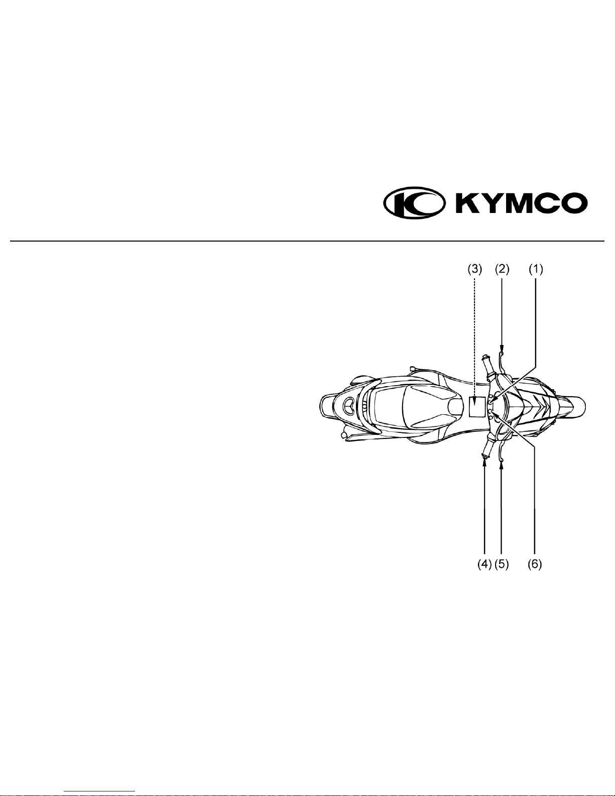
2. PARTS LOCATION
1) Headlights switch – pg 11
electric started button – pg 11
2) Right turn signal indicator light – pg 17
3) Speedometer – pg 16
4) Left turn signal indicator light – pg 17
5) Headlight dimmer switch – pg 12
Passing signal switch – pg 12
Turn signal switch – pg 13
Horn button – pg 13
- 3 -

1) Seat lock – pg 14
2) Fuel fill cap – pg 23
3) Met-in box – pg 14
4) Helmet holder – pg 14
5) Centre hook – pg 15
6) Side stand
7) Centre stand
8) Kickstarter pedal – pg 34
9) Air cleaner housing – pg 43
- 4 -
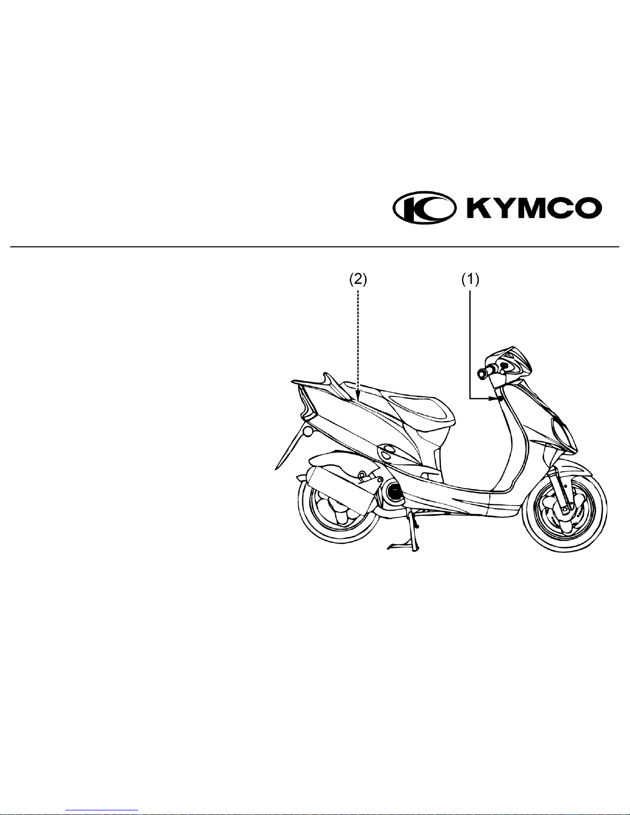
1) Ignition switch – pg 10
2) 2-stroke :
Engine oil tank cap – pg 18
- 5 -
1) 2-stroke: low oil level indicator – pg 17
4 stroke: low beam indicator – pg 17
2) rear brake lever – pg 27
3) battery – pg 48
fuse – pg 50
4) throttle grip
5) front brake lever
6) high beam indicator light – pg 17
- 6 -
- 7 -
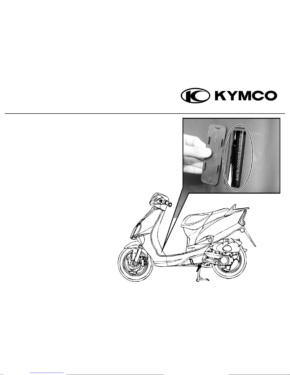
VIN NUMBER
To read the VIN number, remove the cover
from knee shield with a flat head screwdriver.
Always check that the VIN stamped on your
scooter is the same as the VIN written in any
documentation as well as your warranty card.
Please write your VIN for easy reference in the
space provided below.
VIN:
__________________________________
- 8 -
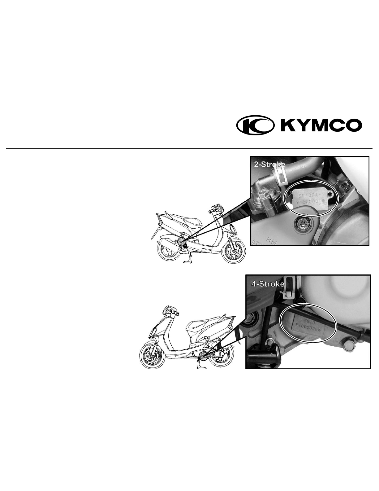
ENGINE NUMBER
The engine number is stamped on the right
engine case.
Please write down your engine number for
easy reference in the space provided below.
ENGINE NUMBER:
____________________________
- 9 -
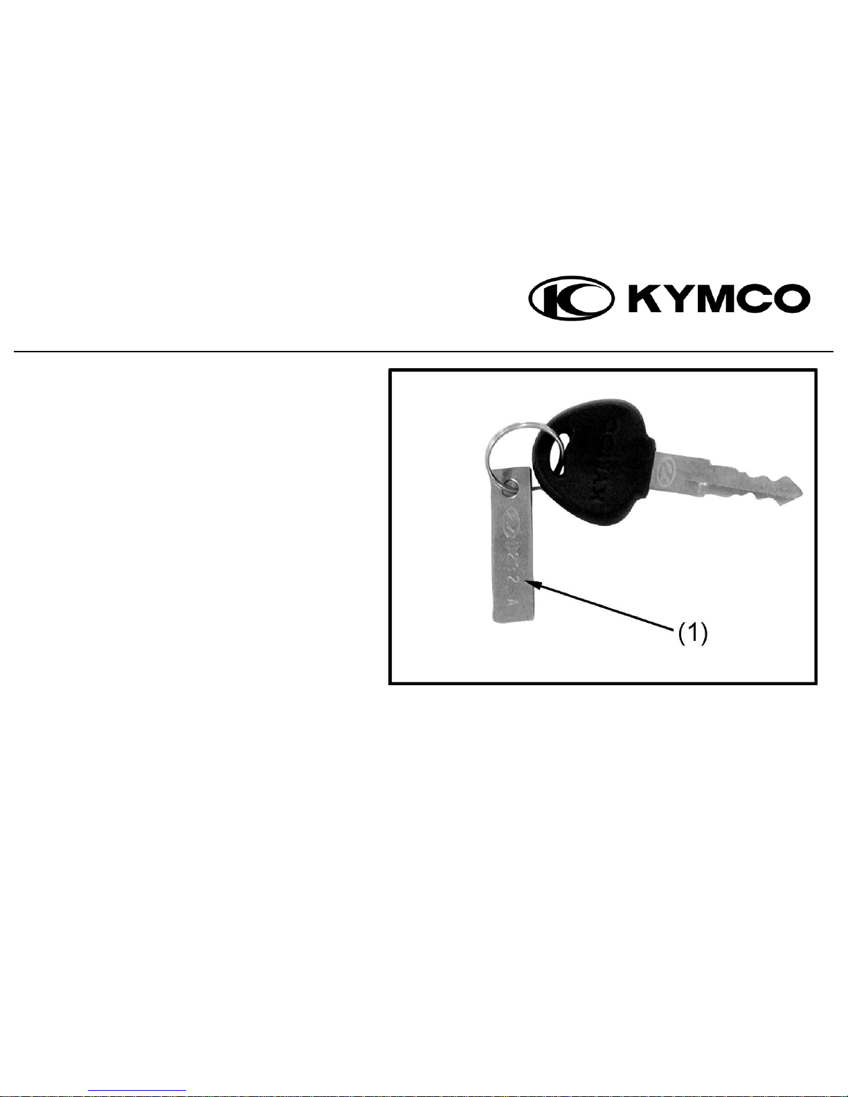
KEY NUMBER
The key number (1) will be required if you need to
order a replacement key.
Please write down your key number for
easy reference in the space provided below.
___________________________________

3. OPERATING INSTRUCTIONS
IGNITION SWITCH / HANDLEBAR LOCK
(1) ON: In this position power is connected and you are able to start the
engine. The key cannot be taken out
(2) OFF: In this position, there is no power connected and the engine will
stop. The key can be taken out.
(3) LOCK: In this position the handlebar is lock. The key can be taken out.
Locking Method
The handlebar can be locked by turning the handlebar to the left as far as
possible. Push and turn the ignition switch key counter clockwise until you
reach the “LOCK” position.
Unlocking Method
Turn the ignition switch key clockwise until you reach the “OFF” position.
The “LOCK” will release automatically.
- 10 -
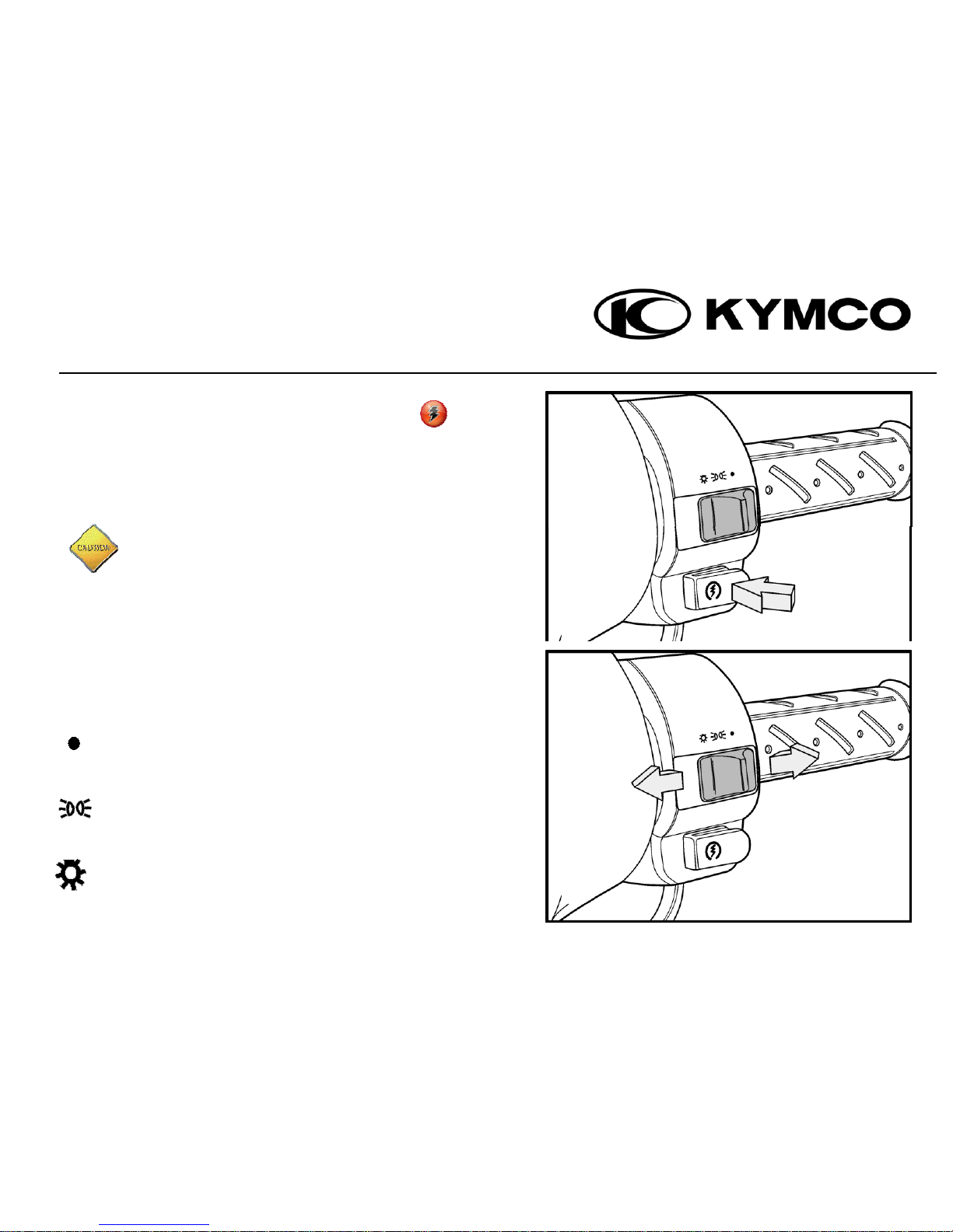
ELECTRIC STARTER BUTTON
To start the engine the ignition switch must be turned to “ON”.
Fully apply the front or rear brake lever to connect the power
and then push the electric starter button.
• To avoid engine damage do not push the electric
start button while the engine is running.
• Before using the electric start button be sure that
The headlight and turn signal switches are in the
“OFF” position.
• Release the electric start button immediately after
the engine has started.
HEADLIGHT SWITCH
In this position the parking light, headlights,
instrument lights and taillight turn off together.
In this position the parking light, instrument lights
and taillight are turned on.
In this position the parking light, headlight, instrument
lights and taillight are turned on.
- 11 -
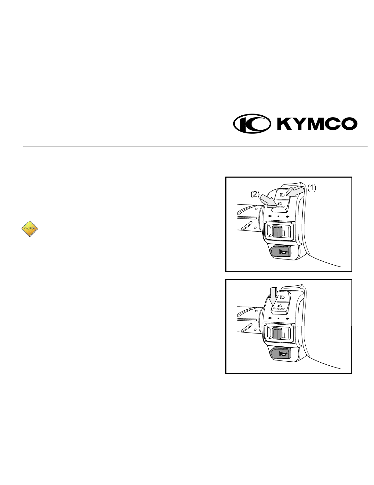
HEADLIGHT DIMMER SWITCH / PASSING SIGNAL SWITCH
(1) Switch to this position for using high beams.
(2) Use low beams when driving in a downtown area or when
there is oncoming traffic. High beams can affect the visibility
of oncoming traffic.
An indicator light appears when you turn your high beams on!
PASSING
This switch allows you to flash your high beams if necessary to
other vehicles.
- 12 -
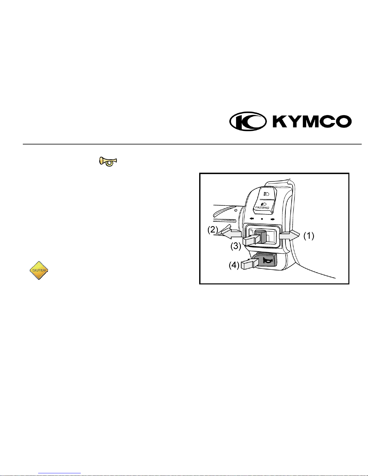
HORN BUTTON / TURN SIGNAL SWITCH
- 13 -
• When the ignition switch key is in the “ON” position,
push the horn button and it will sound.
• Move the turn signal switch to (1) → this will activate the
right turn signal
• Move the turn signal switch to (2) ← this will activate the
left turn signal
• Push the button (3) to release the turn signal switch.
• Press (4) to use the horn.
The turn signal light will NOT release automatically.
Be sure to manually release the turn signal switch.
Failure to do so may affect traffic safety.
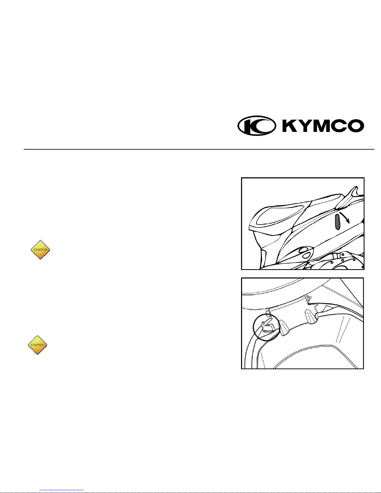
SEAT LOCK / MET-IN BOX (UNDERSEAT STORAGE)
• Unlock the seat – you can store your helmet in the met-in box
(under seat storage)
• To unlock: Stop the engine and turn the ignition switch key to
the “OFF” position. Insert the ignition switch key into the seat
lock and turn it clockwise.
• To lock the seat, push down on it and it will lock automatically.
Make sure the seat is secure before riding
- 14 -
Never put the key inside the seat cushion to lock the seat.
HELMET HOLDER
1. Open the seat using the ignition switch key (see above) and lift seat.
2. Put the helmet retaining ring into the helmet holder
3. Put the seat down and it will lock automatically
To take the helmet out, reverse the order of the above instructions.
When riding be sure you are wearing the helmet and that
it is not still on the scooter. The helmet may interfere
with the safe operation and could result in a loss of control.

CENTRE HOOK
1. To use, pull the hook out from the inside (1)
2. Push the lock lever to the left (2) to unlock and hang your
bag on the hook
3. To remove the bag unlock the lock lever and lift the bag
off the hook.
4. When you’re not using it, push the hook back into its
original position to avoid hooking your clothes while you
are riding.
- 15 -
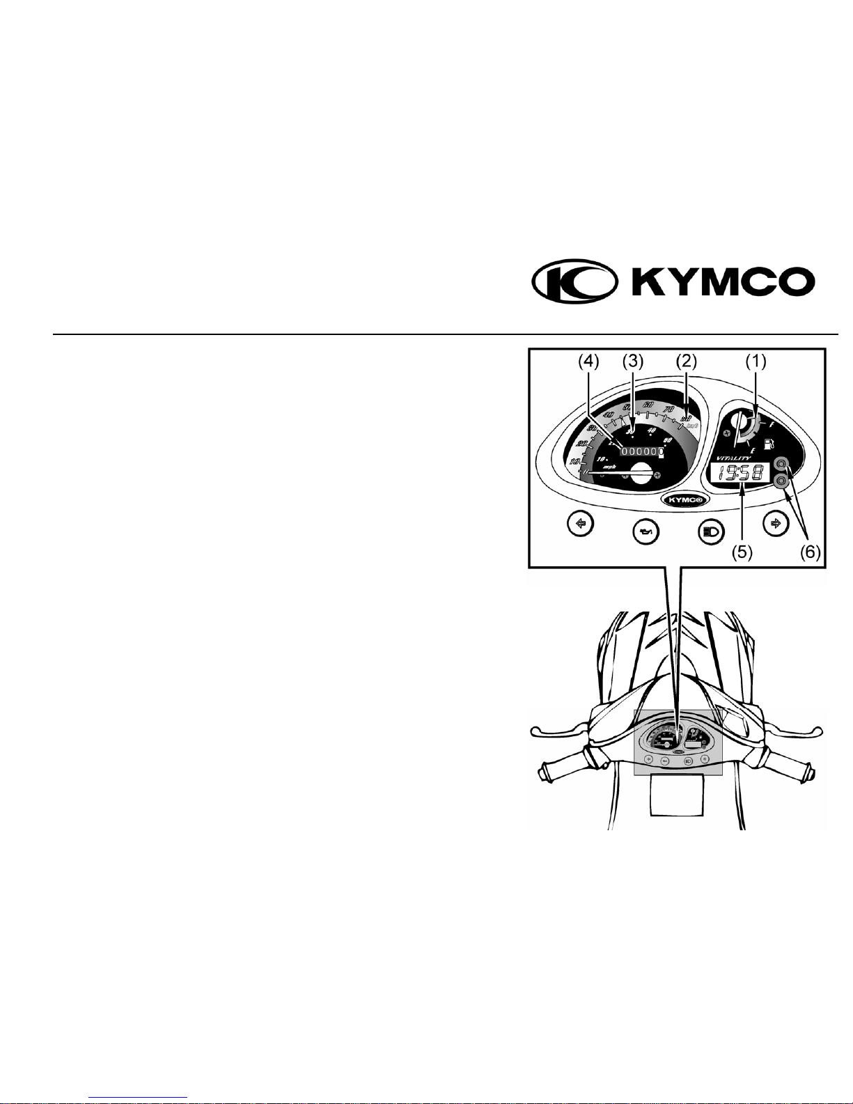
INSTRUMENTS & INDICATORS
(1) FUEL GAUGE: The fuel gauge shows the volume of gasoline in
the fuel tank. If the fuel gauge pointer is at the “E” area, fuel
levels are low or empty. Refill with unleaded gasoline (either 92
or 95) as soon as possible.
(2) SPEEDOMETER (km/hr): The riding speed is indicated in kilometers
per hour.
(3) SPEEDOMETER (mph): The riding speed is indicated in miles per
hour.
(4) ODOMETER: The total riding distance is indicated in kilometers.
The figure in black and white is in units of 100 meters.
(5) CLOCK METER: Displays time and date which can be adjusted
manually.
(6) ADJUST KEY: Used to alter time and date.
- 16 -
 Loading...